





1. Introduction
Ship wakes can significantly impact coastlines, river banks and interactions between ships. Understanding and controlling these wakes can be a great asset in preventing bank erosion and reducing ship energy consumption, as wave resistance plays a substantial role in a ship motion resistance (Havelock Reference Havelock1909). In the deep-water regime, it is known that the wake pattern is generally well described by the Kelvin angle of 19.47 $^\circ$ (Thomson Reference Thomson1887), even though recent research has shown that the wake can appear narrower for high hull Froude numbers ( $Fr^L=U/\sqrt {gL}$, where $L$ is the ship hull length, $U$ the ship velocity and $g$ the gravitational constant) (Rabaud & Moisy Reference Rabaud and Moisy2013; Darmon, Benzaquen & Raphaël Reference Darmon, Benzaquen and Raphaël2014; Moisy & Rabaud Reference Moisy and Rabaud2014; Noblesse et al. Reference Noblesse, He, Zhu, Hong, Zhang, Zhu and Yang2014; Pethiyagoda, McCue & Moroney Reference Pethiyagoda, McCue and Moroney2014). For finite depth, it has been known for more than a century (Havelock Reference Havelock1908) that the wake is greatly influenced by the depth Froude number ( $Fr^h=U/\sqrt {gh}$, where $h$ is the water depth).
The shape and symmetry of wakes can be manipulated through various means, as has been demonstrated in analogue systems. An example is the study by Luo et al. (Reference Luo, Ibanescu, Johnson and Joannopoulos2003), which explores a diverse and intriguing behaviour of Cerenkov radiation in a photonic crystal. The control of symmetry can be achieved by designing a system with an anisotropic dispersion relation. One way to achieve this is by applying a specific shear current, as demonstrated in Ellingsen (Reference Ellingsen2014), Li & Ellingsen (Reference Li and Ellingsen2016) and Smeltzer, Æsøy & Ellingsen (Reference Smeltzer, Æsøy and Ellingsen2019), where asymmetric ship wakes were shown. In our case, we opt for a different approach that relies on a structured bathymetry with constant effective depths. We demonstrate that a ship wake propagating in an anisotropic metamaterial composed of vertically layered bathymetry can generate highly asymmetric wakes. This is due to the ability of metamaterials to modify wave propagation (Maier Reference Maier2017). It should also be noted that such asymmetrical wakes will cause lateral wave resistance as discussed in Li & Ellingsen (Reference Li and Ellingsen2016) and Li, Smeltzer & Ellingsen (Reference Li, Smeltzer and Ellingsen2019).
In the following results, the anisotropic metamaterial on the sea bottom is realized using a vertically layered bathymetry composed of submerged vertical plates (figure 1). We first characterize the wake based on the dispersion relation, as proposed in Luo et al. (Reference Luo, Ibanescu, Johnson and Joannopoulos2003) and Carusotto & Rousseaux (Reference Carusotto and Rousseaux2013). Extending this method to the case of anisotropic dispersion (which was previously obtained with the asymptotic homogenization technique in Maurel et al. Reference Maurel, Marigo, Cobelli, Petitjeans and Pagneux2017), we highlight a wake asymmetry that is studied in relation to the ship's advance direction and speed. Finally, the predictive power of this analysis is demonstrated through quantitative results from laboratory experiments.
Experimental set-up with the metamaterial formed by the subwavelength layered bathymetry. The surface of the metamaterial is approximately  $1.5\,\mathrm {m}\times 1\,\mathrm {m}$ and the region of measurement is $0.7\,\mathrm {m}\times 0.7\,\mathrm {m}$. Parameters: depth over the plates $h^{-}=10\,\mathrm {mm}$, depth between the plates $h^+=55\,\mathrm {mm}$, period of the bathymetry $l=12\,\mathrm {mm}$, filling fraction of the plates $\theta=1/6$ and plates thickness $\theta l=2\,\mathrm {mm}$. (a) Geometry of the layered bathymetry. (b) Sketch of the experiment. (c) Picture of the plates and the ship (sphere).

2. Schematic representation of wakes
In this section, we present the method we use to generate a wake, which is based on the dispersion relation of the medium in which the waves propagate. We start with a constant bathymetry to generate known wakes. We then use the dispersion relation of our anisotropic medium to examine its influence on the wake and how it induces asymmetry.
2.1. Flat bathymetry
To begin with, as a reminder, we consider a flat bathymetry and the classical dispersion relation of water waves (with surface tension due to the scale of the experiment):
 \begin{equation} \omega^2(k)=\left(gk+\frac{\gamma}{\rho} k^3 \right) \tanh (kh), \end{equation}
with  $\omega$ the angular frequency, $k={\lvert }{\boldsymbol {k}}{\rvert }$ the wavenumber, $\boldsymbol {k}$ the wavevector, $h$ the water depth, $g$ the gravitational acceleration ( $9.81\,\mathrm {m}\,\mathrm {s}^{-2}$), $\gamma$ the surface tension ( $72\times 10^{-3}\,\mathrm {N}\,\mathrm {m}^{-1}$ at $25\,^\circ$C) and $\rho$ the water density ( $1000\,\mathrm {kg}\,\mathrm {m}^{-3}$).
Since the wake is defined as the stationary waves in the ship's reference frame, we obtain the dispersion relation of the wake through
 \begin{equation} \varOmega(\boldsymbol{k}) = \omega(\boldsymbol{k}) - \boldsymbol{U}\boldsymbol{\cdot}\boldsymbol{k} = 0, \end{equation}
with  $\varOmega$ the frequency in the ship reference frame and $\boldsymbol {U}$ the ship speed vector.
The dispersion relation of the wake, given by the  $\boldsymbol {k}=(k_x,k_y)$ solution of (2.2) for a given velocity $\boldsymbol {U}$, is shown in figure 2(a,d) for different water depths corresponding to different depth Froude numbers $Fr^h$. We also display the group velocity vectors $\boldsymbol {c}_g=\partial \varOmega (\boldsymbol {k}) / \partial \boldsymbol {k}$ showing the propagation direction of each wavenumber along the dispersion relation of the wake. As done in Luo et al. (Reference Luo, Ibanescu, Johnson and Joannopoulos2003) and Carusotto & Rousseaux (Reference Carusotto and Rousseaux2013), we can construct a schematic representation of the wake by placing these group velocity vectors in the real space (figure 2b,e). This allows us to know the propagation direction of each wavenumber and where the wake energy will be concentrated. This information, simply provided by the dispersion relation, is complemented by theoretical results obtained by Fourier transform assuming a hull Froude number $Fr^L=0.67$ (figure 2(c, f), see Appendix A for the theoretical results) where $L$ is the typical size of the Gaussian pressure field used to model a ship in the simplest manner.
(a,d) Classical dispersion relation of wakes ((2.1) and (2.2), red curve). Arrows, normal to the dispersion relation, indicate the group velocity vectors. Their colours indicate the norm of the wavenumber, see colourbar. (b,e) Schematic representation of the wake using the group velocity vectors; the blue and red dashed lines indicate the minimum and maximum angle of the wake. (c, f) Wakes given by the theoretical model. Parameters:  $U=0.415\,\mathrm {ms}^{-1}$ and $h=47.5$ mm, $Fr^h=0.62$ (a–c) and $h=12$ mm, $Fr^h=1.22$ (d–f).

We can recognize the Kelvin wake (Thomson Reference Thomson1887) corresponding to a low depth Froude number (figure 2c) and a wake in finite depth (Havelock Reference Havelock1908), above the critical  $Fr^h_c=1$, beginning to display Mach cone behaviour (figure 2f). Note that, in both cases, we use a hull Froude number $Fr^L=0.67$ because it corresponds to the experimental measurements to come.
2.2. Layered bathymetry
A vertically layered bathymetry, such as that described in figure 1, can be modelled as an effective two-dimensional anisotropic medium if the wave has a wavelength much larger than the distance  $l$ between the plates. The two principal axes of this anisotropic medium are $\boldsymbol {X}$ perpendicular to the plates and $\boldsymbol {Y}$ parallel to the plates. Unsurprisingly, the angle $\alpha$ between the axis $\boldsymbol {X}$ and the ship velocity $\boldsymbol {U}$ will be an important parameter in generating the asymmetry of the wake. The dispersion relation over the layered bathymetry was proposed (without the surface tension term) in Maurel et al. (Reference Maurel, Marigo, Cobelli, Petitjeans and Pagneux2017) using asymptotic homogenization techniques:
 \begin{align} \omega^2(\boldsymbol{K})=\left(g \frac{\boldsymbol{K}^{\sf T}\boldsymbol{\cdot}\boldsymbol{h}\boldsymbol{\cdot}\boldsymbol{K}} {\sqrt{\boldsymbol{K}^{\sf T}\boldsymbol{\cdot}\boldsymbol{h}^2\boldsymbol{\cdot}\boldsymbol{K}}} + \frac{\gamma}{\rho}|\boldsymbol{K}|^{3}\right) \tanh(\sqrt{\boldsymbol{K}^{\sf T}\boldsymbol{\cdot}\boldsymbol{h}^2\boldsymbol{\cdot}\boldsymbol{K}}) \quad \text{with}\ \boldsymbol{h}=\begin{pmatrix} h_X & 0 \\ 0 & h_Y \end{pmatrix}, \end{align}
where  $\boldsymbol {K}$ is the wavevector in the basis $(\boldsymbol {X},\boldsymbol {Y})$, $\boldsymbol {K}^{\sf T}$ the transpose wavevector, $\boldsymbol {K}=R_\alpha ^{\sf T} \boldsymbol {k}$ the rotation between the two basis ( $R_\alpha$ conventional rotation matrix). The anisotropic effective parameters (effective water depths $h_X$, $h_Y$) of the structure are obtained using the homogenization of the three-dimensional water-wave problem developed in Maurel et al. (Reference Maurel, Marigo, Cobelli, Petitjeans and Pagneux2017).
Actually, capillary waves propagate in the deep-water regime over the structured bathymetry, whose minimum depth is  $h^-=10$ mm which corresponds to a $\tanh (kh^-)=0.996$ for a wavelength of 2 cm. Therefore, we consider that the bathymetry has negligible impact when capillary effects have to be taken into account and, in (2.3), to the gravity term proportional to $g$, we have added the term $(\gamma/\rho)|\boldsymbol{K}|^3$ representing the surface tension effect in the same way as in the classical dispersion relation (2.1).
In the experiments to come, the geometrical parameters of the layered bathymetry, shown in the figure 1, are set to  $h^{-}=10$ mm, $h^+=55$ mm, $l=12$ mm, $\theta =1/6$ and $l/h^+=0.22$.
The homogenization of this set-up gives the effective depths with  $h_{Y}=47.5\,\mathrm {mm}$ given by the volume average $h_{Y}=\theta h^{-}+(1-\theta )h^+$ and $h_{X}=12\,\mathrm {mm}$ obtained by a single numerical resolution of the two-dimensional potential flow in a unit cell of the periodic medium, as detailed in Maurel et al. (Reference Maurel, Marigo, Cobelli, Petitjeans and Pagneux2017).
Since the plates are thin ( $\theta =1/6$) and the length of the periodicity is small in front of the highest water depth ( $l/h_+=0.22$), $h_X$ and $h_Y$ are respectively close to $h^-$ and $h^+$ (Maurel et al. Reference Maurel, Marigo, Cobelli, Petitjeans and Pagneux2017; Marangos & Porter Reference Marangos and Porter2021). The geometrical parameters have been chosen in order to have a significantly anisotropic medium (quantified by $h_{Y}/h_{X}$) while avoiding too small water depths, which are prone to produce strong nonlinear effects. We quantify the nonlinear effects with the Ursell number $Ur=H\lambda ^2/h^3\approx 10$ considering a wave amplitude of approximately $H\approx 1$ mm, a mean wavelength of $\lambda \approx 100$ mm and the water depth over the plates $h=h^-=10$ mm. The anisotropic dispersion relation of the wake (using (2.3) in (2.2) for the parameters $U=0.415\,\mathrm {ms}^{-1}$ and $\alpha =39^\circ$) is shown in figure 3(a). The asymmetry of the dispersion relation between the upper-half plane ( $k_y>0$) and the lower-half plane ( $k_y<0$) is clearly visible and implies the asymmetry of the wake in the real space as exhibited in figure 3(b). The ‘lower wake’ ( $\,y<0$) seems to be similar to a wake with a Froude number greater than one (figure 3(b) compared to figure 2e). Remarkably, the ‘upper wake’ ( $\,y>0$) is more peculiar; long waves are ahead of the ship ( $x>0$). In contrast, short waves propagate similarly in both the upper and lower wakes, as expected from the behaviour of the dispersion relation at large $k$ observed in figure 3(a). This is simply due to the fact that the bathymetry does not affect short waves that are in the deep-water regime. Overall, in figure 3(b), the wake pattern looks similar to that obtained in Ellingsen (Reference Ellingsen2014) because our bathymetry has an effect that increases with wavelength, as in Ellingsen (Reference Ellingsen2014), where the shear current is a Couette flow with increasing velocity with depth.
(a) Anisotropic dispersion relation ((2.3) and (2.2), red curve) of an asymmetrical wake with  $U=0.415\,\mathrm {ms}^{-1}$, $h_-=12$ mm and $h_+=47.5$ mm. The colour of each arrow indicates the norm of the wavenumber, see colourbar. (b) Schematic representation of the wake using the group velocity vectors, the inset shows the layered bathymetry with the red arrow indicating the ship propagation, the blue and red dashed lines indicate the minimum and maximum angle of the wake. (c) Angle difference, between the upper and lower wake, of the group velocity vector. $\delta \theta _g$.

To quantify the wake asymmetry, we proceed as follows. First, we define  $\theta _g(\boldsymbol {k})$, the angle between the group velocity vector and the horizontal axis in figure 3(b). Then we can compare the upper and lower wakes for a given wavenumber with $\delta \theta _g(k)={\lvert }{\theta _g(\kern0.7pt y>0)}{\rvert }-{\lvert }{\theta _g(\kern0.7pt y<0)}{\rvert }$ (figure 3c). As mentioned above, long waves are most affected by bathymetry. Next, we use $I_g(\alpha,U)=\int _{0}^\infty \delta \theta _g(k)\,\text {d}{k}$ to quantify the global asymmetry of the wake. This quantity is displayed in figure 4 when we vary the ship velocity $U$ and the angle between the ship and the bathymetry $\alpha$. Note that, the example shown in figure 3 is closed to the maximum asymmetry $I_g$ and the same parameters will be used for the first experiment. Although less asymmetric according to $I_g$, a second experiment will be performed with a different pair of parameters ( $U,\alpha$) exhibiting a different type of asymmetry.
Integral of the angle difference for the group velocity vector  $I_g$ as a function of the ship velocity $U$ and the angle between the ship and the bathymetry $\alpha$. The circle corresponds to the parameters used in figure 3. In the following experiments, both the circle and the cross parameters will be chosen.

3. Experimental set-up
The experiment is conducted in a tank 1.5 m wide and 4 m long. Within this tank, we place our layered bathymetry over an area 1 m wide and 1.5 m long. These dimensions are large enough to avoid unwanted reflections from the tank walls. The measurement domain,  $0.7\,\mathrm {m}\times 0.7\,\mathrm {m}$, is positioned at the end of the varying bathymetry (see figure 1) to observe an established wake.
The ship is a sphere with a diameter of 80 mm; this sphere is fixed to a guided bar tracked by a motor which provides a constant ship velocity. The sphere is submerged by 5 mm of water, so the diameter of the surface in contact with the water is  $L\simeq40$ mm; this dimension is considered as the size of the ship. For the sake of simplicity, we have chosen a sphere even if other shapes of ships would have potentially different effects on the wake.
We measure the wave field using the optical method called free-surface synthetic Schlieren (FS-SS), which is based on the analysis of the refracted image of a random dot pattern placed below the free surface (Moisy, Rabaud & Salsac Reference Moisy, Rabaud and Salsac2009). Since we do not have a flat bottom (due to the varying bathymetry), we paint black dots on the top of the plates to obtain a reference flat surface for the FS-SS method (figure 1c). We acquire 170 images of the surface deformation with an acquisition frequency of 250 Hz over the measurement domain  $0.7\,\mathrm {m}\times 0.7\,\mathrm {m}$.
To suppress the experimental noise, we average by staying in the reference frame of the moving ship. This averaging would also remove possible non-stationary waves, such as turbulent wake, but it can be noted that considering a Reynolds number based on the size  $L$ of the ship $Re\simeq 2\times 10^4$ such waves should be negligible, which is confirmed by naked-eye visualization. Going to the scale of a real boat $L\approx 8$ m, the Reynolds number would be of the order of $Re\simeq 5\times 10^7$ (maintaining the Froude number), and in this case the turbulent wake might not be negligible.
4. Experimental results
For the first experimental results, we consider the same configuration as in the theoretical study of figure 3 with the layered bathymetry  $h^{-}=10$ mm and $h^+=55$ mm (effective water depths $h_X=12$ mm, $h_Y=47.5$ mm), an angle $\alpha =-39^\circ$ and a ship speed set to $U=0.415$ m s $^{-1}$ (circle in figure 4). The Froude number based on the depth varies between $Fr^h=0.62$ and $Fr^h=1.22$ and the hull Froude number is $Fr^L\simeq 0.7$ which is of the order of the Froude number for a typical boat.
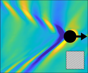
Overall, the measured wake (figure 5a) is clearly asymmetric between the upper wake ( $\,y>0$) and the lower wake ( $\,y<0$), with even a part of the long waves ahead of the ship. This experimental result is in good agreement with the schematic representation of the wake using the group velocity (figure 3b). The lower wake ( $\,y<0$) is similar to that over a flat bathymetry and a small constant water depth $h=h_X$ (figure 2f). The upper wake ( $\,y>0$) is the most interesting: on the one hand, the shortest waves are concentrated along the apparent angle which is defined as the angle with the maximum amplitude, but, on the other hand, we can observe a large spread of long waves from the apparent angle to the maximum angle. Part of those long waves are even ahead of the ship, showing that, in such configuration, some waves have a group velocity higher than the ship speed. We focus on this point in § 5 where we theoretically investigated the effect of hull Froude number on preferentially exciting long waves.
Surface elevation for the parameters  $h^{-}=10\,\mathrm {mm}$, $h^+=55\,\mathrm {mm}$, $h_{X}=12\,\mathrm {mm}$, $h_{Y}=47.5\,\mathrm {mm}$, $\alpha =-39^\circ$ and $U=0.415\,\mathrm {ms}^{-1}$. (a) Experimental results (wave amplitude in mm); the blue and red dashed lines indicate the minimum and maximum angle of the wake; the inset shows the layered bathymetry with the red arrow indicating the ship propagation. (c) Fast Fourier transform of the experimental results; the red curve corresponds to the theoretical dispersion relation (2.2) and (2.3).(d) Theoretical wave amplitude obtained by Fourier transform (discretization of (A2)) and (b) the coefficients of its discrete inverse both with arbitrary amplitude.

For comparison with theory, we compute wake patterns by Fourier transform technique (developed in Appendix A) for the same parameters as in the experiment. The good agreement between experimental and theoretical results shows the validity of the anisotropic dispersion relation (2.3) and this is even clearer on the Fourier transform of the surface deformation (figure 5c,d).
Note, however, that the pressure Gaussian patch assumption in the theory is idealized and should be improved in order to have a more quantitative model.
Another experiment is performed in a more symmetrical case. We measure a wake (figure 6) similar to that with a Froude number of less than one where the long waves are inside the apparent angle (figure 2c). For this case, we use the same bathymetry as before with an angle  $\alpha =-62^\circ$ and a ship speed of $U=0.47$ m s $^{-1}$ (cross in figure 4). Due to the anisotropy, a remarkable effect is that the waves inside the apparent angle (transversal waves) are oblique.
Surface elevation for the parameters  $h^{-}=10\,\mathrm {mm}$, $h^+=55\,\mathrm {mm}$, $h_{X}=12\,\mathrm {mm}$, $h_{Y}=47.5\,\mathrm {mm}$, $\alpha =-62^\circ$ and $U=0.47\,\mathrm {ms}^{-1}$. (a) Experimental results (wave amplitude in mm); the red dashed lines indicate the maximum angle of the wake; the inset shows the layered bathymetry with the red arrow indicating the ship propagation. The colour scale is saturated to emphasize the transverse waves. (c) Fast Fourier transform of the experimental results; the red curve corresponds to the theoretical dispersion relation (2.2) and (2.3).(d) Theoretical wave amplitude obtained by Fourier transform (discretization of (A2)) and (b) the coefficients of its discrete inverse both with arbitrary amplitude.

The effect of anisotropy can also be seen in the Fourier space (figure 6c,d), where the symmetries  $k_x\rightarrow -k_x$ and $k_y\rightarrow -k_y$ have been broken (as in figure 5c,d).
As mentioned in the introduction, wakes can be manipulated as well by shear currents as it has been observed in Smeltzer et al. (Reference Smeltzer, Æsøy and Ellingsen2019), with similar type of asymmetric wakes.
5. Hull Froude number and non-dispersive wake
In this section, we consider the evaluation of the effect of the ship size using theoretical results, i.e. we will compute wakes with Fourier transform varying the hull Froude number over the same bathymetry. The ship size in the theoretical model is given by the typical size  $L$ of the Gaussian pressure pattern which controls the wavelength spectrum excited. Since long waves are more affected by the stratified bathymetry, we need a larger ship to enhance their excitation (hence a smaller hull Froude number $Fr^L=U/\sqrt {gL}$). In the following, we observe ship wakes up to 10 times larger than that used in the experiment. It should be noted that the Gaussian pressure patch is a highly idealized modelling of the source effect, which would certainly need to be enriched (e.g. boundary-layer effects and laminar-to-turbulent transition or even more importantly bow/stern-wave interference) for such large ships.
Figure 7 shows wakes for the same parameters as the experimental results of figure 5 but with larger ship sizes. In the experiment  $Fr^L\simeq 0.7$, and here we consider three different values of $Fr^L$ ranging from 0.47 to 0.21 corresponding to boat sizes from 80 to 400 mm. We see that the amplitude of the short waves decreases as the size of the ship increases until only non-dispersive long waves remain. In figure 7(c), the wake appears simply as a Mach cone (or a Froude cone in our case) but with the peculiarity that the upper wake is completely ahead of the ship.
Theoretical wakes (and their associated Fourier transform) on the layered bathymetry with the parameters  $h_{X}=12\,\mathrm {mm}$, $h_{Y}=47.5\,\mathrm {mm}$, $\alpha =-39^\circ$ and a ship speed $U=0.42\,\mathrm {ms}^{-1}$. The size of the ship $L$ varies from 80 to 400 mm (2 to 10 times the ship size in the experiments), with associated hull Froude number $Fr^L$ from 0.47 to 0.21. The dashed curves indicate the schematic representation of the wake.

6. Conclusion
We show, experimentally and theoretically, that a layered bathymetry can generate highly asymmetrical wakes due to the anisotropy induced by the structured bottom. By construction, submerged structures do not affect the shorter wavelengths while long waves are able to present the strongest asymmetric behaviour. To design this asymmetry of the wake patterns, a simple two-dimensional effective medium model obtained from homogenization of the full three-dimensional water-wave problem is used and is shown to accurately predict the experimental results. In addition to the asymmetry of the wake, it is observed that the bottom structuration can induce long waves to propagate ahead of the ship. The ability to modify ship wakes can have a significant impact on mitigating coastal and riverbank erosion, as well as controlling wave resistance to reduce ship fuel consumption.
Funding
The authors acknowledge the support of the ANR under grant no. ANR-21-CE30-0046 CoProMM.
Declaration of interests
The authors report no conflict of interest.
Appendix A. Theoretical results
The theoretical results are obtained using the Fourier transform of a source in constant motion in a medium with a given relation dispersion following the same lines as in Li & Ellingsen (Reference Li and Ellingsen2016). We choose a pressure Gaussian patch with a typical length  $L$ given by $F(x,y)=\exp {(-(x^2+y^2)/\sigma ^2)}$ with $\sigma =L/3$. To obtain a good agreement between experimental and theoretical results, the value $\sigma$ is fixed considering $L=40$ mm the size of our sphere at the free surface. In the Fourier space the source is given by: $F_k(k_x,k_y)=\exp {(-(k_x^2+k_y^2)({1}/{\sigma ^2}))}$.
Solving the problem of a moving source of pressure  $F$ with constant velocity $U$ on an inviscid and incompressible fluid, as in Li & Ellingsen (Reference Li and Ellingsen2016), we obtain the surface elevation:
 \begin{equation} {\eta}(x,y)=\frac{1}{4{\rm \pi}^2}\frac{1}{\rho g}\iint \hat{\eta}(k_x,k_y) \exp({{\rm i}k_x x + {\rm i}k_y y})\,\text{d}k_x\,\text{d}k_x \end{equation}
with
 \begin{equation} \hat{\eta}(k_x,k_y)=\frac{F_k\omega^2}{k_x^2 U^2-\omega^2+2{\rm i}\epsilon k_x U-\epsilon^2}, \end{equation}
where  $\omega ^2(k_x,k_y)$ is the dispersion relation of the bathymetry given by (2.1) (flat bathymetry) or (2.3) (layered bathymetry). The small parameter $\epsilon$ controls the attenuation to avoid aliasing. Note that the theoretical surface elevation results are displayed in arbitrary units.


 Open access

