





1. Introduction
The sphere is one of the most fundamental three-dimensional bluff body configurations. Despite its simple geometry, the flow around it exhibits complex behaviour that has been extensively studied over several decades. Achenbach (Reference Achenbach1972) demonstrated that the flow is highly sensitive to the Reynolds number, defined as $Re = U_\infty d / \nu$
, where
$Re = U_\infty d / \nu$
, where $U_\infty$
is the free-stream velocity,
$U_\infty$
is the free-stream velocity, $d$
is the sphere diameter and
$d$
is the sphere diameter and $\nu$
is the kinematic viscosity of air. In the subcritical Reynolds number regime, the boundary layer typically separates early, at approximately
$\nu$
is the kinematic viscosity of air. In the subcritical Reynolds number regime, the boundary layer typically separates early, at approximately $80^\circ$
from the stagnation point, resulting in a relatively high drag coefficient of around 0.5. To reduce this drag, various flow control strategies have been developed, primarily aiming to delay flow separation and suppress wake formation (Choi, Jeon & Kim Reference Choi, Jeon and Kim2008). These strategies are broadly categorised as passive or active, depending on whether external energy input is required. Among passive methods, surface modifications such as dimples (Choi, Jeon & Choi Reference Choi, Jeon and Choi2006; Beratlis, Balaras & Squires Reference Beratlis, Balaras and Squires2019), surface roughness (Achenbach Reference Achenbach1974) and trip wires (Son et al. Reference Son, Choi, Jeon and Choi2011) have garnered significant attention due to their simplicity, energy efficiency and practical feasibility.
$80^\circ$
from the stagnation point, resulting in a relatively high drag coefficient of around 0.5. To reduce this drag, various flow control strategies have been developed, primarily aiming to delay flow separation and suppress wake formation (Choi, Jeon & Kim Reference Choi, Jeon and Kim2008). These strategies are broadly categorised as passive or active, depending on whether external energy input is required. Among passive methods, surface modifications such as dimples (Choi, Jeon & Choi Reference Choi, Jeon and Choi2006; Beratlis, Balaras & Squires Reference Beratlis, Balaras and Squires2019), surface roughness (Achenbach Reference Achenbach1974) and trip wires (Son et al. Reference Son, Choi, Jeon and Choi2011) have garnered significant attention due to their simplicity, energy efficiency and practical feasibility.
For bluff body flows, passive control can be implemented through either two-dimensional (2-D) or three-dimensional (3-D) geometric modifications (Choi et al. Reference Choi, Jeon and Kim2008). In 2-D bluff bodies, such as circular cylinders and bluff trailing-edge geometries, introducing spanwise- or azimuthally varying 3-D surface features has been shown to enhance vortex interactions and suppress both mean drag and unsteady fluctuations (Zdravkovich Reference Zdravkovich1981; Tombazis & Bearman Reference Tombazis and Bearman1997). However, for inherently 3-D bluff bodies such as spheres, the baseline wake is already three-dimensional, and it remains unclear whether additional 3-D surface modifications can yield further aerodynamic benefits. As noted by Choi et al. (Reference Choi, Jeon and Kim2008), the effectiveness of such modifications on fully 3-D bluff bodies has yet to be systematically assessed.
This study addresses the aforementioned gap by introducing a novel passive flow control strategy, in which surface protrusions are discretely arranged along the azimuthal direction of the sphere, herein referred to as partial protrusions. Although various geometric parameters such as protrusion size, spacing and surface coverage can influence aerodynamic performance, the present work focuses specifically on the effects of protrusion number at fixed total protruded area. The primary objective is to determine whether partial-protrusion configurations can achieve greater drag reduction than continuous full protrusion and to elucidate the underlying flow mechanisms responsible for any observed enhancement. To isolate the effect of partial-protrusion coverage, its performance is compared with that of a smooth sphere and a fully covered sphere with protrusions distributed over the entire azimuth.
The remainder of this paper is organised as follows. Section 2 describes the experimental methodology, including model design and measurement techniques. Section 3 presents the drag measurements (§ 3.1) and detailed flow field analysis for partial-protrusion configurations with low (§ 3.2.1) and high (§ 3.2.2) protrusion numbers, followed by a comparison of flow unsteadiness between the two cases (§ 3.2.3), to elucidate the mechanisms responsible for drag reduction. Section 4 concludes the paper by summarising the key findings and discussing their implications.
(a) Schematic of the spherical model and an enlarged cross-sectional view of a protrusion. (b) Modular configuration of the spherical model, consisting of four parts: upstream, control, middle and tail. (c) Front view of various sphere configurations: smooth sphere, sphere with partial protrusions (e.g. $N =$
4, 8, 16, where
$N =$
4, 8, 16, where $N$
denotes the number of protrusions) and full-protrusion sphere. (d) Schematic of the experimental set-up for drag and flow velocity measurements in the closed-circuit wind tunnel.
$N$
denotes the number of protrusions) and full-protrusion sphere. (d) Schematic of the experimental set-up for drag and flow velocity measurements in the closed-circuit wind tunnel.

2. Experimental set-up
An overview of the experimental apparatus and the sphere configurations used in this study is shown in figure 1. All experiments were conducted in a closed-circuit wind tunnel with a test section measuring 0.5 m in height, 0.5 m in width and 1.2 m in length. The free-stream turbulence intensity was maintained below 0.8 % at an inlet velocity of 20 m s−1. The blockage ratio was approximately 7 %, which is sufficiently low to ensure negligible wall interference.
The sphere had a diameter $d = 150$
mm and was mounted at the centre of the test section (
$d = 150$
mm and was mounted at the centre of the test section ( $y$
–
$y$
– $z$
) plane using a 12 mm-diameter steel rod with a length of 850 mm. The rod was rigidly supported by steel wires to suppress flow-induced vibrations and avoid mechanical resonance, following prior designs by Chae et al. (Reference Chae, Lee, Kim and Lee2019). The sphere was fabricated from ABS plastic via CNC machining to ensure high-dimensional accuracy. Surface protrusions were based on a trip-wire cross-sectional profile previously shown to be effective in drag reduction (Son et al. Reference Son, Choi, Jeon and Choi2011). Each protrusion had a height (
$z$
) plane using a 12 mm-diameter steel rod with a length of 850 mm. The rod was rigidly supported by steel wires to suppress flow-induced vibrations and avoid mechanical resonance, following prior designs by Chae et al. (Reference Chae, Lee, Kim and Lee2019). The sphere was fabricated from ABS plastic via CNC machining to ensure high-dimensional accuracy. Surface protrusions were based on a trip-wire cross-sectional profile previously shown to be effective in drag reduction (Son et al. Reference Son, Choi, Jeon and Choi2011). Each protrusion had a height ( $k$
) of 1 mm, corresponding to a height-to-diameter ratio of
$k$
) of 1 mm, corresponding to a height-to-diameter ratio of $0.667 \times 10^{-2}$
. Protrusions were installed at a polar angle of
$0.667 \times 10^{-2}$
. Protrusions were installed at a polar angle of $50^\circ$
from the stagnation point.
$50^\circ$
from the stagnation point.
To allow modular variation of protrusion arrangements, the spherical model was divided into four parts based on the polar angle: (i) an upstream part ( $0^\circ$
–
$0^\circ$
– $49^\circ$
), (ii) a control part (
$49^\circ$
), (ii) a control part ( $49^\circ$
–
$49^\circ$
– $52^\circ$
), (iii) a middle part (
$52^\circ$
), (iii) a middle part ( $52^\circ$
–
$52^\circ$
– $140^\circ$
) and (iv) a tail part (
$140^\circ$
) and (iv) a tail part ( $140^\circ$
–
$140^\circ$
– $180^\circ$
), as shown in figure 1(b). Only the control part contained protrusions and could be readily replaced to generate different partial-protrusion configurations. Three classes of spherical models were tested: a smooth sphere with no protrusions, a full-protrusion sphere with continuous azimuthal coverage (hereafter referred to as the full-protrusion case) and partial-protrusion spheres with the number of protrusions
$180^\circ$
), as shown in figure 1(b). Only the control part contained protrusions and could be readily replaced to generate different partial-protrusion configurations. Three classes of spherical models were tested: a smooth sphere with no protrusions, a full-protrusion sphere with continuous azimuthal coverage (hereafter referred to as the full-protrusion case) and partial-protrusion spheres with the number of protrusions $N$
varied from 4 to 20 (see figure 1
c). In all cases, the total azimuthal coverage was fixed at
$N$
varied from 4 to 20 (see figure 1
c). In all cases, the total azimuthal coverage was fixed at $180^\circ$
, and the angular span of each protrusion was given by
$180^\circ$
, and the angular span of each protrusion was given by $\phi _p = 180^\circ /N$
. The
$\phi _p = 180^\circ /N$
. The $i$
th protrusion was positioned in the range
$i$
th protrusion was positioned in the range $180^\circ (2i - 1)/N \lt \phi \lt 180^\circ {\times}\, 2i/N$
, where
$180^\circ (2i - 1)/N \lt \phi \lt 180^\circ {\times}\, 2i/N$
, where $i = 1, 2, \ldots, N$
. The spacing between protrusions was set equal to their angular span.
$i = 1, 2, \ldots, N$
. The spacing between protrusions was set equal to their angular span.
The drag force was measured using a miniature load cell (CAS BCL-2L) embedded inside the sphere, as shown in the inset of figure 1(d). The measurement uncertainty was less than $\pm 2.5\,\%$
. In this study, drag was measured over a free-stream velocity range of
$\pm 2.5\,\%$
. In this study, drag was measured over a free-stream velocity range of $4\,{\textrm{m s}}^{-1} \leqslant U_\infty \leqslant 32\,\textrm{m}\,\textrm{s}^{-1}$
, corresponding to Reynolds numbers
$4\,{\textrm{m s}}^{-1} \leqslant U_\infty \leqslant 32\,\textrm{m}\,\textrm{s}^{-1}$
, corresponding to Reynolds numbers $0.4 \times 10^5 \leqslant Re \leqslant 3.2 \times 10^5$
. For each flow condition, drag data were averaged over durations ranging from 60 to 500 s. The non-dimensional averaging time, defined as
$0.4 \times 10^5 \leqslant Re \leqslant 3.2 \times 10^5$
. For each flow condition, drag data were averaged over durations ranging from 60 to 500 s. The non-dimensional averaging time, defined as $t^*_{{avg}} = t_{{avg}} U_\infty / d$
, exceeded 13 000 for all cases, satisfying the convergence criterion
$t^*_{{avg}} = t_{{avg}} U_\infty / d$
, exceeded 13 000 for all cases, satisfying the convergence criterion $t^*_{{avg}} \gt 2000$
reported by Norman & McKeon (Reference Norman and McKeon2011). The analogue voltage was digitised using an NI PCIe-6351 data acquisition system and transferred to a PC for post-processing (see red lines in figure 1
d).
$t^*_{{avg}} \gt 2000$
reported by Norman & McKeon (Reference Norman and McKeon2011). The analogue voltage was digitised using an NI PCIe-6351 data acquisition system and transferred to a PC for post-processing (see red lines in figure 1
d).
Time-averaged flow fields were obtained using a particle image velocimetry (PIV) system consisting of a dual-head Nd:YAG laser, a CCD camera and a timing hub. A 3 mm-thick laser sheet illuminated the $x$
–
$x$
– $y$
(streamwise–axial) plane at the mid-span of the sphere (
$y$
(streamwise–axial) plane at the mid-span of the sphere ( $z = 0$
). To minimise laser reflection, the sphere was coated with matte black paint. The PIV analysis employed interrogation windows of
$z = 0$
). To minimise laser reflection, the sphere was coated with matte black paint. The PIV analysis employed interrogation windows of $16 \times 16$
pixels with 75 % overlap. To capture azimuthal (
$16 \times 16$
pixels with 75 % overlap. To capture azimuthal ( $\phi$
) variations in the wake, the sphere was mounted on a manual rotational stage, allowing repeatable rotation about a horizontal axis through the stagnation point. Measurements were conducted at azimuthal positions within the range
$\phi$
) variations in the wake, the sphere was mounted on a manual rotational stage, allowing repeatable rotation about a horizontal axis through the stagnation point. Measurements were conducted at azimuthal positions within the range $-0.44 \leqslant \phi /\phi _p \leqslant 0.44$
. Here, negative and positive
$-0.44 \leqslant \phi /\phi _p \leqslant 0.44$
. Here, negative and positive $\phi /\phi _p$
values correspond to the protruded and smoothed sides, respectively, while
$\phi /\phi _p$
values correspond to the protruded and smoothed sides, respectively, while $\phi /\phi _p = 0$
represents the boundary between the two sides (see, for example, the
$\phi /\phi _p = 0$
represents the boundary between the two sides (see, for example, the $N = 4$
configuration in figure 1
c). The minimum azimuthal increment was 2.5
$N = 4$
configuration in figure 1
c). The minimum azimuthal increment was 2.5 $^\circ$
, corresponding to 0.056
$^\circ$
, corresponding to 0.056 $\phi _p$
and 0.22
$\phi _p$
and 0.22 $\phi _p$
for
$\phi _p$
for $N = 4$
and
$N = 4$
and $N = 16$
, respectively.
$N = 16$
, respectively.
Surface oil flow visualisations were conducted in the same wind tunnel using a mixture of paraffin oil and titanium dioxide. The mixture was carefully applied to the entire surface of the sphere to ensure a uniform coating prior to setting the tunnel to the target flow speed. The free-stream velocity was then maintained until the oil reached a steady distribution on the surface. The viscosity of the oil mixture was systematically adjusted to ensure sufficient sensitivity to aerodynamic shear stress while remaining relatively insensitive to gravitational effects. The resulting flow patterns on the horizontal ( $x$
–
$x$
– $z$
) plane were recorded using a digital camera (Olympus E-PL5).
$z$
) plane were recorded using a digital camera (Olympus E-PL5).
3. Results and discussions
3.1. Drag measurements
Figure 2 presents the drag coefficient, defined as $C_D = D / (0.5 \rho U_\infty ^2 A)$
, for the smooth sphere, the full-protrusion sphere and the partial-protrusion spheres, where
$C_D = D / (0.5 \rho U_\infty ^2 A)$
, for the smooth sphere, the full-protrusion sphere and the partial-protrusion spheres, where $D$
is the drag force,
$D$
is the drag force, $\rho$
is the air density and
$\rho$
is the air density and $A$
is the cross-sectional area of the sphere. The drag coefficient of the smooth sphere remains nearly constant at approximately 0.5 across the entire Reynolds number range, as shown in figure 2(a), and is in good agreement with the results of Achenbach (Reference Achenbach1972). In contrast, the full-protrusion configuration exhibits a similar
$A$
is the cross-sectional area of the sphere. The drag coefficient of the smooth sphere remains nearly constant at approximately 0.5 across the entire Reynolds number range, as shown in figure 2(a), and is in good agreement with the results of Achenbach (Reference Achenbach1972). In contrast, the full-protrusion configuration exhibits a similar $C_D$
at low Reynolds numbers but shows a sharp decrease as
$C_D$
at low Reynolds numbers but shows a sharp decrease as $Re$
increases, reaching approximately 0.22 at
$Re$
increases, reaching approximately 0.22 at $Re \approx 1.2 \times 10^5$
. Beyond this point,
$Re \approx 1.2 \times 10^5$
. Beyond this point, $C_D$
decreases slightly and asymptotically approaches 0.18. This trend is consistent with the results of Son et al. (Reference Son, Choi, Jeon and Choi2011), who used a trip wire with the same height-to-diameter ratio (
$C_D$
decreases slightly and asymptotically approaches 0.18. This trend is consistent with the results of Son et al. (Reference Son, Choi, Jeon and Choi2011), who used a trip wire with the same height-to-diameter ratio ( $k/d = 0.667 \times 10^{-2}$
) and installation angle (
$k/d = 0.667 \times 10^{-2}$
) and installation angle ( $\theta = 50^\circ$
).
$\theta = 50^\circ$
).
(a) Variations of drag coefficient ( $C_D$
) with Reynolds number for the smooth sphere (filled triangles) and the full-protrusion sphere (filled squares), compared with previous experimental data by Son et al. (Reference Son, Choi, Jeon and Choi2011) (open squares). (b) Variations of
$C_D$
) with Reynolds number for the smooth sphere (filled triangles) and the full-protrusion sphere (filled squares), compared with previous experimental data by Son et al. (Reference Son, Choi, Jeon and Choi2011) (open squares). (b) Variations of $C_D$
with Reynolds number for spheres with partial-protrusion configurations at different numbers of protrusions (
$C_D$
with Reynolds number for spheres with partial-protrusion configurations at different numbers of protrusions ( $N = 4$
–20).
$N = 4$
–20).

Figure 2(b) shows the variations of $C_D$
with Reynolds number for spheres with partial-protrusion configurations, where the number of protrusions
$C_D$
with Reynolds number for spheres with partial-protrusion configurations, where the number of protrusions $N$
is varied. For
$N$
is varied. For $N = 4$
,
$N = 4$
, $C_D$
remains similar to that of the smooth sphere at low Reynolds numbers and begins to decrease beyond
$C_D$
remains similar to that of the smooth sphere at low Reynolds numbers and begins to decrease beyond $Re \approx 1.0 \times 10^5$
. It reaches a minimum value of 0.24 at
$Re \approx 1.0 \times 10^5$
. It reaches a minimum value of 0.24 at $Re = 2.1 \times 10^5$
, then slightly increases and converges to approximately 0.26. As
$Re = 2.1 \times 10^5$
, then slightly increases and converges to approximately 0.26. As $N$
increases to 8,
$N$
increases to 8, $C_D$
decreases more rapidly and reaches a lower minimum of 0.22 at a lower Reynolds number (
$C_D$
decreases more rapidly and reaches a lower minimum of 0.22 at a lower Reynolds number ( $Re = 1.6 \times 10^5$
). As
$Re = 1.6 \times 10^5$
). As $N$
increases further to 16, the minimum
$N$
increases further to 16, the minimum $C_D$
further decreases and the reduction persists across higher Reynolds numbers, leading to a lower converged value of 0.18 at high
$C_D$
further decreases and the reduction persists across higher Reynolds numbers, leading to a lower converged value of 0.18 at high $Re$
. However, increasing
$Re$
. However, increasing $N$
beyond 16 does not yield additional improvement, as the
$N$
beyond 16 does not yield additional improvement, as the $C_D$
curve for
$C_D$
curve for $N = 20$
closely overlaps with that of
$N = 20$
closely overlaps with that of $N = 16$
throughout the tested
$N = 16$
throughout the tested $Re$
range.
$Re$
range.
These results indicate that the number of protrusions plays a crucial role in determining the drag reduction effectiveness of the partial-protrusion configurations. For instance, when $N = 4$
,
$N = 4$
, $C_D$
is lower than that of the smooth sphere but remains higher than that of the full-protrusion case across the entire
$C_D$
is lower than that of the smooth sphere but remains higher than that of the full-protrusion case across the entire $Re$
range, indicating a relatively weak drag reduction effect. However, as
$Re$
range, indicating a relatively weak drag reduction effect. However, as $N$
increases to 16,
$N$
increases to 16, $C_D$
is reduced by up to 67 % at
$C_D$
is reduced by up to 67 % at $Re = 1.8 \times 10^5$
compared with the smooth sphere, achieving a drag reduction that is 7 percentage points greater than that of the full-protrusion configuration. This finding suggests that, despite having only half the azimuthal coverage, well-spaced partial protrusions with
$Re = 1.8 \times 10^5$
compared with the smooth sphere, achieving a drag reduction that is 7 percentage points greater than that of the full-protrusion configuration. This finding suggests that, despite having only half the azimuthal coverage, well-spaced partial protrusions with $N \geqslant 16$
can outperform the full-protrusion configuration. The underlying flow mechanisms responsible for this enhanced performance are further examined in § 3.2 through detailed PIV measurements and surface oil flow visualisation.
$N \geqslant 16$
can outperform the full-protrusion configuration. The underlying flow mechanisms responsible for this enhanced performance are further examined in § 3.2 through detailed PIV measurements and surface oil flow visualisation.
3.2. Flow characteristics of spheres with partial protrusions
To investigate the drag reduction mechanism induced by partial protrusions, the flow fields were analysed for spheres with $N = 4$
and
$N = 4$
and $N = 16$
configurations at
$N = 16$
configurations at $Re = 1.8 \times 10^5$
, where the
$Re = 1.8 \times 10^5$
, where the $N = 16$
case exhibits maximum drag reduction.
$N = 16$
case exhibits maximum drag reduction.
Contours of normalised time-averaged tangential velocity ( $\overline {u_\theta }/U_\infty$
) for the (a) smooth, (b) full-protrusion and (c–h) partial-protrusion (
$\overline {u_\theta }/U_\infty$
) for the (a) smooth, (b) full-protrusion and (c–h) partial-protrusion ( $N = 4$
) spheres at six azimuthal positions (
$N = 4$
) spheres at six azimuthal positions ( $\phi /\phi _p = -0.44$
,
$\phi /\phi _p = -0.44$
, $-0.22$
,
$-0.22$
, $-0.11$
,
$-0.11$
, $0.11$
,
$0.11$
, $0.22$
and
$0.22$
and $0.44$
) at
$0.44$
) at $Re = 1.8 \times 10^5$
. The dashed lines in the top-left schematic indicate the azimuthal measurement planes corresponding to figure 3(c–h). The lower-left inset provides an enlarged view of the contours near the flow-separation region at
$Re = 1.8 \times 10^5$
. The dashed lines in the top-left schematic indicate the azimuthal measurement planes corresponding to figure 3(c–h). The lower-left inset provides an enlarged view of the contours near the flow-separation region at $\phi /\phi _p = 0.22$
. (i) Normalised time-averaged tangential velocity profiles above the surface for the partial-protrusion case (
$\phi /\phi _p = 0.22$
. (i) Normalised time-averaged tangential velocity profiles above the surface for the partial-protrusion case ( $N = 4$
) at three
$N = 4$
) at three $\phi /\phi _p$
locations: protruded side (
$\phi /\phi _p$
locations: protruded side ( $\phi /\phi _p = -0.44$
, red), boundary (
$\phi /\phi _p = -0.44$
, red), boundary ( $\phi /\phi _p = 0$
, green) and smoothed side (
$\phi /\phi _p = 0$
, green) and smoothed side ( $\phi /\phi _p = 0.44$
, blue). Wall-normal positions where
$\phi /\phi _p = 0.44$
, blue). Wall-normal positions where $\overline {u_\theta }/U_\infty = 0$
are marked with open symbols.
$\overline {u_\theta }/U_\infty = 0$
are marked with open symbols.

3.2.1. Flow characteristics for $N = 4$

Figure 3(a–h) presents the contours of normalised time-averaged tangential velocity ( $\overline {u_\theta }/U_\infty$
) for the smooth sphere (figure 3
a), the full-protrusion sphere (figure 3
b) and the partial-protrusion (
$\overline {u_\theta }/U_\infty$
) for the smooth sphere (figure 3
a), the full-protrusion sphere (figure 3
b) and the partial-protrusion ( $N = 4$
) sphere (figure 3
c–h). For the partial-protrusion sphere, results are shown at six azimuthal positions, with three on the protruded side (figure 3
c–e) and three on the smoothed side (figure 3
f–h), as indicated in the top-left schematic.
$N = 4$
) sphere (figure 3
c–h). For the partial-protrusion sphere, results are shown at six azimuthal positions, with three on the protruded side (figure 3
c–e) and three on the smoothed side (figure 3
f–h), as indicated in the top-left schematic.
The flow over the smooth sphere exhibits a broad wake region with strong backflow (figure 3 a), whereas the flow over the full-protrusion sphere shows significantly delayed separation, resulting in a much smaller wake (figure 3 b). This improvement is attributed to enhanced boundary-layer disturbances induced by the protrusion, which promote early transition and delay separation. Notably, this reduction in wake size corresponds to a drag reduction of approximately 60 %, as shown in figure 2(a). For the partial-protrusion sphere, the wake on the protruded side (figure 3 c–e) closely resembles that of the full-protrusion sphere (figure 3 b). In contrast, the wake on the smoothed side (figure 3 f–h) is noticeably narrower than that of the smooth sphere (figure 3 a) and is even smaller than that on the protruded side. In particular, a small recirculating flow region is observed near the surface on the smoothed side after separation (see the inset in figure 3 g). The detailed mechanism responsible for this feature will be examined later.
To quantitatively compare the wake widths on both sides, the profiles of normalised time-averaged tangential velocity above the sphere’s surface ( $x_r/R = 0$
) are plotted in figure 3(i). Here,
$x_r/R = 0$
) are plotted in figure 3(i). Here, $x_r$
denotes the wall-normal distance from the surface. Open symbols indicate the wall-normal locations where
$x_r$
denotes the wall-normal distance from the surface. Open symbols indicate the wall-normal locations where $\overline {u_\theta }/U_\infty = 0$
, representing the wake boundaries. On the protruded side (open squares), the wake boundary progressively moves farther from the surface as the flow develops downstream, reaching
$\overline {u_\theta }/U_\infty = 0$
, representing the wake boundaries. On the protruded side (open squares), the wake boundary progressively moves farther from the surface as the flow develops downstream, reaching $x_r/R \approx 0.20$
at
$x_r/R \approx 0.20$
at $\theta = 140^{\circ }$
. In contrast, on the smoothed side (open triangles), the wake boundary remains near
$\theta = 140^{\circ }$
. In contrast, on the smoothed side (open triangles), the wake boundary remains near $x_r/R = 0.05$
even at
$x_r/R = 0.05$
even at $\theta = 140^{\circ }$
, indicating a considerably narrower wake. At the protrusion boundary (
$\theta = 140^{\circ }$
, indicating a considerably narrower wake. At the protrusion boundary ( $\phi /\phi _p = 0$
), the wake boundary (open diamonds) lies between those of the protruded and smoothed sides.
$\phi /\phi _p = 0$
), the wake boundary (open diamonds) lies between those of the protruded and smoothed sides.
(a) Contours of normalised time-averaged vorticity ( $\overline {\omega } R/U_\infty$
) for the partial-protrusion sphere (
$\overline {\omega } R/U_\infty$
) for the partial-protrusion sphere ( $N = 4$
) at different azimuthal positions (
$N = 4$
) at different azimuthal positions ( $\phi /\phi _p = -0.44$
,
$\phi /\phi _p = -0.44$
, $-0.11$
,
$-0.11$
, $0$
,
$0$
, $0.11$
, and
$0.11$
, and $0.44$
). (b) Normalised time-averaged tangential velocity profiles above the surface for the partial-protrusion case (
$0.44$
). (b) Normalised time-averaged tangential velocity profiles above the surface for the partial-protrusion case ( $N = 4$
) at various
$N = 4$
) at various $\phi /\phi _p$
values. (c) Variations in flow-separation angle (
$\phi /\phi _p$
values. (c) Variations in flow-separation angle ( $\theta _s$
) for the
$\theta _s$
) for the $N = 4$
case as a function of
$N = 4$
case as a function of $\phi /\phi _p$
, compared with the smooth (blue line) and full-protrusion (red line) spheres.
$\phi /\phi _p$
, compared with the smooth (blue line) and full-protrusion (red line) spheres.

Since the wake size is strongly influenced by the separation point, figure 4 examines how the development of the boundary layer varies as $\phi /\phi _p$
increases from
$\phi /\phi _p$
increases from $-0.44$
(protruded side) to 0.44 (smoothed side). Figure 4(a) shows the contours of normalised time-averaged spanwise vorticity (
$-0.44$
(protruded side) to 0.44 (smoothed side). Figure 4(a) shows the contours of normalised time-averaged spanwise vorticity ( $\overline {\omega }R/U_\infty$
) at
$\overline {\omega }R/U_\infty$
) at $\phi /\phi _p = -0.44$
,
$\phi /\phi _p = -0.44$
, $-0.11$
,
$-0.11$
, $0$
,
$0$
, $0.11$
and
$0.11$
and $0.44$
. Figure 4(b) presents profiles of normalised time-averaged tangential velocity above the sphere’s surface at various streamwise locations (
$0.44$
. Figure 4(b) presents profiles of normalised time-averaged tangential velocity above the sphere’s surface at various streamwise locations ( $\theta = 88^\circ$
–
$\theta = 88^\circ$
– $124^\circ$
) for three azimuthal positions. Figure 4(c) shows the variations in separation angle (
$124^\circ$
) for three azimuthal positions. Figure 4(c) shows the variations in separation angle ( $\theta _s$
) as a function of
$\theta _s$
) as a function of $\phi /\phi _p$
, compared with those of the smooth and full-protrusion spheres. Here, the separation point is defined as the location where the wall-normal gradient of the time-averaged tangential velocity drops below
$\phi /\phi _p$
, compared with those of the smooth and full-protrusion spheres. Here, the separation point is defined as the location where the wall-normal gradient of the time-averaged tangential velocity drops below $0.005U_\infty$
. For the smooth sphere, flow separation occurs at approximately
$0.005U_\infty$
. For the smooth sphere, flow separation occurs at approximately $\theta _s = 83^\circ$
(see the blue line in figure 4
c), which is consistent with previous studies conducted in the subcritical Reynolds number regime (Achenbach Reference Achenbach1972; Chae et al. Reference Chae, Lee, Kim and Lee2019). In this regime, the boundary layer remains laminar without significant disturbances.
$\theta _s = 83^\circ$
(see the blue line in figure 4
c), which is consistent with previous studies conducted in the subcritical Reynolds number regime (Achenbach Reference Achenbach1972; Chae et al. Reference Chae, Lee, Kim and Lee2019). In this regime, the boundary layer remains laminar without significant disturbances.
As the azimuthal location shifts from the protruded side to the smoothed side (i.e. with increasing $\phi /\phi _p$
), the boundary layer progressively lifts away from the surface (figure 4
a), accompanied by a gradual reduction in near-wall momentum, as evidenced by the tangential velocity profiles (see, for example, the profile at
$\phi /\phi _p$
), the boundary layer progressively lifts away from the surface (figure 4
a), accompanied by a gradual reduction in near-wall momentum, as evidenced by the tangential velocity profiles (see, for example, the profile at $\theta = 96^\circ$
in figure 4
b). Accordingly, the flow separates progressively earlier as
$\theta = 96^\circ$
in figure 4
b). Accordingly, the flow separates progressively earlier as $\phi /\phi _p$
increases, showing a decrease in the separation angle (
$\phi /\phi _p$
increases, showing a decrease in the separation angle ( $\theta _s$
), as demonstrated in figure 4(c). Specifically, this trend can be quantified as follows: at
$\theta _s$
), as demonstrated in figure 4(c). Specifically, this trend can be quantified as follows: at $\phi /\phi _p = -0.44$
, the boundary layer separates from the surface at
$\phi /\phi _p = -0.44$
, the boundary layer separates from the surface at $\theta _s = 114^\circ$
. The separation angle remains nearly constant up to
$\theta _s = 114^\circ$
. The separation angle remains nearly constant up to $\phi /\phi _p = -0.11$
, beyond which it decreases rapidly, with the separation point shifting upstream to
$\phi /\phi _p = -0.11$
, beyond which it decreases rapidly, with the separation point shifting upstream to $\theta _s = 102^\circ$
at the boundary (
$\theta _s = 102^\circ$
at the boundary ( $\phi /\phi _p = 0$
). Thereafter, on the smoothed side,
$\phi /\phi _p = 0$
). Thereafter, on the smoothed side, $\theta _s$
continues to move upstream with increasing
$\theta _s$
continues to move upstream with increasing $\phi /\phi _p$
and stabilises at
$\phi /\phi _p$
and stabilises at $\theta _s = 97^\circ$
beyond
$\theta _s = 97^\circ$
beyond $\phi /\phi _p = 0.22$
. Notably,
$\phi /\phi _p = 0.22$
. Notably, $\theta _s$
on the protruded side is comparable to that of the full-protrusion sphere, whereas
$\theta _s$
on the protruded side is comparable to that of the full-protrusion sphere, whereas $\theta _s$
on the smoothed side increases by approximately
$\theta _s$
on the smoothed side increases by approximately $15^\circ$
relative to the smooth sphere. This observation is consistent with the velocity profiles at
$15^\circ$
relative to the smooth sphere. This observation is consistent with the velocity profiles at $\theta = 96^\circ$
, where the smoothed side maintains a positive wall-normal velocity gradient even beyond the typical separation point of the smooth sphere.
$\theta = 96^\circ$
, where the smoothed side maintains a positive wall-normal velocity gradient even beyond the typical separation point of the smooth sphere.
(a) Contours of instantaneous normalised tangential velocity for the partial-protrusion sphere ( $N = 4$
) on the smoothed side (
$N = 4$
) on the smoothed side ( $\phi /\phi _p = 0.44$
). (b) Surface oil flow patterns for the partial-protrusion sphere (
$\phi /\phi _p = 0.44$
). (b) Surface oil flow patterns for the partial-protrusion sphere ( $N = 4$
); the red line indicates the location of the surface protrusion. (c) Temporal variations of the instantaneous separation angle for the smooth sphere (black line) and the smoothed side (
$N = 4$
); the red line indicates the location of the surface protrusion. (c) Temporal variations of the instantaneous separation angle for the smooth sphere (black line) and the smoothed side ( $\phi /\phi _p = 0.44$
) of the partial-protrusion sphere (
$\phi /\phi _p = 0.44$
) of the partial-protrusion sphere ( $N = 4$
; blue line). (d) Probability distributions of the instantaneous separation angle for the smooth, full-protrusion and partial-protrusion (
$N = 4$
; blue line). (d) Probability distributions of the instantaneous separation angle for the smooth, full-protrusion and partial-protrusion ( $N = 4$
) spheres at
$N = 4$
) spheres at $\phi /\phi _p = -0.44$
and
$\phi /\phi _p = -0.44$
and $0.44$
. The solid lines represent Gaussian fits of the separation-angle distributions.
$0.44$
. The solid lines represent Gaussian fits of the separation-angle distributions.

The delayed separation on the smoothed side is hypothesised to result from interactions between the smoothed and protruded sides. Son et al. (Reference Son, Choi, Jeon and Choi2011) reported that spheres with a trip wire exhibit lower surface pressure upstream of the separation point compared with smooth spheres. Given the geometric similarity between the protrusion and trip wire (figure 1
a), it is reasonable to expect that the protruded side would experience lower pressure than the smoothed side before separation, thereby inducing a lateral flow from the smoothed to the protruded side near the surface. In the present study, such a near-wall lateral flow is hypothesised to shift low-momentum fluid from the smoothed side to the protruded side, effectively increasing the near-wall momentum on the smoothed side and delaying flow separation. In this sense, the lateral flow may act similarly to localised suction, as it removes low-momentum fluid near the smoothed surface, which is a known mechanism for delaying separation in sphere flows (Fransson, Konieczny & Alfredsson Reference Fransson, Konieczny and Alfredsson2004; Ramsay, Sellier & Ho Reference Ramsay, Sellier and Ho2020). Figure 5(a) shows two representative instantaneous flow fields for the $N = 4$
case on the smoothed side, illustrating that the separation delay exhibits temporal unsteadiness. This unsteadiness likely arises due to the large azimuthal spacing between adjacent protrusions (
$N = 4$
case on the smoothed side, illustrating that the separation delay exhibits temporal unsteadiness. This unsteadiness likely arises due to the large azimuthal spacing between adjacent protrusions ( $\phi _p = 45^\circ$
for
$\phi _p = 45^\circ$
for $N = 4$
; see figure 1
c), which may be too large to sustain continuous suppression of separation. Notably, the region marked by an ellipse in the right panel of figure 5(a) appears to represent a near-wall lateral flow directed from the protruded side toward the smoothed side. This location (
$N = 4$
; see figure 1
c), which may be too large to sustain continuous suppression of separation. Notably, the region marked by an ellipse in the right panel of figure 5(a) appears to represent a near-wall lateral flow directed from the protruded side toward the smoothed side. This location ( $\theta \approx 128^\circ$
) lies downstream of the separation point on the protruded side, where the surface pressure on the protruded side becomes higher than that on the smoothed side (Son et al. Reference Son, Choi, Jeon and Choi2011), likely driving the observed reversed lateral flow. The lateral flow can be identified in the surface oil flow patterns shown in figure 5(b) for the partial-protrusion sphere. The red line indicates the location of the surface protrusion. On the protruded side (left), the flow separates farther downstream than on the smoothed side (right), consistent with the separation angles presented in figure 4(c). Near the boundary between the two sides (vertical centreline), an oblique flow is observed around
$\theta \approx 128^\circ$
) lies downstream of the separation point on the protruded side, where the surface pressure on the protruded side becomes higher than that on the smoothed side (Son et al. Reference Son, Choi, Jeon and Choi2011), likely driving the observed reversed lateral flow. The lateral flow can be identified in the surface oil flow patterns shown in figure 5(b) for the partial-protrusion sphere. The red line indicates the location of the surface protrusion. On the protruded side (left), the flow separates farther downstream than on the smoothed side (right), consistent with the separation angles presented in figure 4(c). Near the boundary between the two sides (vertical centreline), an oblique flow is observed around $\theta = 110^\circ$
, directed from the protruded side toward the smoothed side (to the right) and bending downstream. This oblique lateral flow appears to enhance the positive tangential momentum within the wake of the smoothed side, leading to the formation of an intermittent separation bubble, as shown in the right panel of figure 5(a). Such intermittent formation of the separation bubble is likely responsible for the smaller wake observed on the smoothed side (figure 3
i) despite the earlier onset of flow separation compared with the protruded side (figure 4
c). This intermittent bubble formation may also explain the small recirculating flow region observed near the surface on the smoothed side in the inset of figure 3(g), which is considered a time-averaged footprint of the transient separation bubble.
$\theta = 110^\circ$
, directed from the protruded side toward the smoothed side (to the right) and bending downstream. This oblique lateral flow appears to enhance the positive tangential momentum within the wake of the smoothed side, leading to the formation of an intermittent separation bubble, as shown in the right panel of figure 5(a). Such intermittent formation of the separation bubble is likely responsible for the smaller wake observed on the smoothed side (figure 3
i) despite the earlier onset of flow separation compared with the protruded side (figure 4
c). This intermittent bubble formation may also explain the small recirculating flow region observed near the surface on the smoothed side in the inset of figure 3(g), which is considered a time-averaged footprint of the transient separation bubble.
To quantitatively examine the unsteadiness of the flow-separation delay on the smoothed side of the partial-protrusion sphere, figure 5(c) presents the temporal variation of the separation angle for the smooth sphere and for the smoothed side of the partial-protrusion sphere ( $N = 4$
). The frame number denotes the image sequence captured during the PIV measurements. The separation angle on the smoothed side (blue line) exhibits significantly larger fluctuations and higher mean values compared with that of the smooth sphere (black line). Figure 5(d) shows the probability distributions of the instantaneous separation angle for the protruded side (
$N = 4$
). The frame number denotes the image sequence captured during the PIV measurements. The separation angle on the smoothed side (blue line) exhibits significantly larger fluctuations and higher mean values compared with that of the smooth sphere (black line). Figure 5(d) shows the probability distributions of the instantaneous separation angle for the protruded side ( $\phi /\phi _p = -0.44$
) and smoothed side (
$\phi /\phi _p = -0.44$
) and smoothed side ( $\phi /\phi _p = 0.44$
) of the partial-protrusion sphere. For comparison, the results for the smooth and full-protrusion spheres are also included. The smooth sphere and full-protrusion sphere exhibit narrow standard deviations of
$\phi /\phi _p = 0.44$
) of the partial-protrusion sphere. For comparison, the results for the smooth and full-protrusion spheres are also included. The smooth sphere and full-protrusion sphere exhibit narrow standard deviations of $1.96^\circ$
and
$1.96^\circ$
and $2.28^\circ$
, with mean separation angles of
$2.28^\circ$
, with mean separation angles of $84^\circ$
and
$84^\circ$
and $116^\circ$
, respectively, indicating that their separation remains relatively steady. In contrast, the smoothed side of the
$116^\circ$
, respectively, indicating that their separation remains relatively steady. In contrast, the smoothed side of the $N = 4$
case shows the widest distribution, with a mean separation angle of
$N = 4$
case shows the widest distribution, with a mean separation angle of $96^\circ$
and a standard deviation of
$96^\circ$
and a standard deviation of $6.14^\circ$
, implying that its instantaneous separation angle is approximately three times more unsteady than that of the smooth sphere. On the protruded side (
$6.14^\circ$
, implying that its instantaneous separation angle is approximately three times more unsteady than that of the smooth sphere. On the protruded side ( $\phi /\phi _p = -0.44$
), the standard deviation decreases to
$\phi /\phi _p = -0.44$
), the standard deviation decreases to $4.39^\circ$
, suggesting that the unsteadiness of the instantaneous separation angle becomes slightly weaker; however, it still remains about twice as large as that of the full-protrusion sphere. These observations indicate that the enhanced unsteadiness of the separation angle occurs not only on the smoothed side, where the lateral flow directly influences the boundary-layer behaviour, but also on the protruded side, demonstrating the strong dynamic coupling between the boundary-layer separations on the two sides. The mean separation angle on both the protruded and smoothed sides of the partial-protrusion sphere (approximately
$4.39^\circ$
, suggesting that the unsteadiness of the instantaneous separation angle becomes slightly weaker; however, it still remains about twice as large as that of the full-protrusion sphere. These observations indicate that the enhanced unsteadiness of the separation angle occurs not only on the smoothed side, where the lateral flow directly influences the boundary-layer behaviour, but also on the protruded side, demonstrating the strong dynamic coupling between the boundary-layer separations on the two sides. The mean separation angle on both the protruded and smoothed sides of the partial-protrusion sphere (approximately $105^\circ$
) is greater than that of both the smooth and full-protrusion spheres (approximately
$105^\circ$
) is greater than that of both the smooth and full-protrusion spheres (approximately $100^\circ$
). Consequently, despite having only half the protrusion length compared with the full-protrusion sphere, the partial-protrusion configuration achieves a drag reduction of 38 %, which is 8 percentage points higher than half of the reduction achieved by the full-protrusion case (60 %), as illustrated in figure 2(b).
$100^\circ$
). Consequently, despite having only half the protrusion length compared with the full-protrusion sphere, the partial-protrusion configuration achieves a drag reduction of 38 %, which is 8 percentage points higher than half of the reduction achieved by the full-protrusion case (60 %), as illustrated in figure 2(b).
3.2.2. Flow characteristics for
$N = 16$

Figure 6(a–f) presents the contours of normalised time-averaged tangential velocity ( $\overline {u_\theta }/U_\infty$
) for the smooth sphere (figure 6
a), the full-protrusion sphere (figure 6
b) and the partial-protrusion sphere with
$\overline {u_\theta }/U_\infty$
) for the smooth sphere (figure 6
a), the full-protrusion sphere (figure 6
b) and the partial-protrusion sphere with $N = 16$
(figure 6
c–f). For the partial-protrusion sphere, results are shown at four azimuthal positions, with two on the protruded side (figure 6
c,d) and two on the smoothed side (figure 6
e,f), as indicated in the top-left schematic. For the
$N = 16$
(figure 6
c–f). For the partial-protrusion sphere, results are shown at four azimuthal positions, with two on the protruded side (figure 6
c,d) and two on the smoothed side (figure 6
e,f), as indicated in the top-left schematic. For the $N = 16$
sphere, the wakes formed on both the protruded side (
$N = 16$
sphere, the wakes formed on both the protruded side ( $\phi /\phi _p = {-0.44, -0.22}$
) and the smoothed side (
$\phi /\phi _p = {-0.44, -0.22}$
) and the smoothed side ( $\phi /\phi _p = {0.22, 0.44}$
) are comparable to, or even smaller than, the wake formed behind the full-protrusion sphere (figure 6
b). This enhancement in wake suppression is attributed to the intensified interaction between the two sides, which becomes stronger as the azimuthal spacing between adjacent protrusions decreases from
$\phi /\phi _p = {0.22, 0.44}$
) are comparable to, or even smaller than, the wake formed behind the full-protrusion sphere (figure 6
b). This enhancement in wake suppression is attributed to the intensified interaction between the two sides, which becomes stronger as the azimuthal spacing between adjacent protrusions decreases from $\phi _p = 45^\circ$
(for
$\phi _p = 45^\circ$
(for $N = 4$
) to
$N = 4$
) to $11.25^\circ$
(for
$11.25^\circ$
(for $N = 16$
) (see figure 1
c). A comparison between the contours on the protruded side (figure 6
c,d) and those on the smoothed side (figure 6
e,f) reveals that the wake sizes on both sides are nearly the same. To quantitatively compare the wake width between the two sides, figure 6(g) presents the profiles of normalised time-averaged tangential velocity (
$N = 16$
) (see figure 1
c). A comparison between the contours on the protruded side (figure 6
c,d) and those on the smoothed side (figure 6
e,f) reveals that the wake sizes on both sides are nearly the same. To quantitatively compare the wake width between the two sides, figure 6(g) presents the profiles of normalised time-averaged tangential velocity ( $\overline {u_\theta }/U_\infty$
) above the sphere’s surface. The wake boundaries, defined by the locations where
$\overline {u_\theta }/U_\infty$
) above the sphere’s surface. The wake boundaries, defined by the locations where $\overline {u_\theta }/U_\infty = 0$
, are marked with open symbols: squares for the protruded side, triangles for the smoothed side and diamonds for the boundary between them. These positions exhibit negligible differences, indicating that the wake sizes on the two sides are almost the same. This behaviour contrasts with the
$\overline {u_\theta }/U_\infty = 0$
, are marked with open symbols: squares for the protruded side, triangles for the smoothed side and diamonds for the boundary between them. These positions exhibit negligible differences, indicating that the wake sizes on the two sides are almost the same. This behaviour contrasts with the $N = 4$
case (figure 3
i), where the wake gradually decreased toward the smoothed side. Therefore, as
$N = 4$
case (figure 3
i), where the wake gradually decreased toward the smoothed side. Therefore, as $N$
increases, the interaction between the protruded and smoothed sides becomes stronger, leading to a more symmetric wake structure.
$N$
increases, the interaction between the protruded and smoothed sides becomes stronger, leading to a more symmetric wake structure.
Contours of normalised time-averaged tangential velocity ( $\overline {u_\theta }/U_\infty$
) for the (a) smooth, (b) full-protrusion and (c–f) partial-protrusion (
$\overline {u_\theta }/U_\infty$
) for the (a) smooth, (b) full-protrusion and (c–f) partial-protrusion ( $N = 16$
) spheres at four azimuthal positions (
$N = 16$
) spheres at four azimuthal positions ( $\phi /\phi _p = -0.44$
,
$\phi /\phi _p = -0.44$
, $-0.22$
,
$-0.22$
, $0.22$
and
$0.22$
and $0.44$
) at
$0.44$
) at $Re = 1.8 \times 10^5$
. The dashed lines in the top-left schematic indicate the azimuthal measurement planes corresponding to figure 6(c–f). (g) Normalised time-averaged tangential velocity profiles above the surface for the partial-protrusion case (
$Re = 1.8 \times 10^5$
. The dashed lines in the top-left schematic indicate the azimuthal measurement planes corresponding to figure 6(c–f). (g) Normalised time-averaged tangential velocity profiles above the surface for the partial-protrusion case ( $N = 16$
) at three
$N = 16$
) at three $\phi /\phi _p$
locations: protruded side (
$\phi /\phi _p$
locations: protruded side ( $\phi /\phi _p = -0.44$
, red), boundary (
$\phi /\phi _p = -0.44$
, red), boundary ( $\phi /\phi _p = 0$
, green) and smoothed side (
$\phi /\phi _p = 0$
, green) and smoothed side ( $\phi /\phi _p = 0.44$
, blue). Wall-normal positions where
$\phi /\phi _p = 0.44$
, blue). Wall-normal positions where $\overline {u_\theta }/U_\infty = 0$
are marked with open symbols.
$\overline {u_\theta }/U_\infty = 0$
are marked with open symbols.

(a) Contours of normalised time-averaged vorticity ( $\overline {\omega } R/U_\infty$
) for the partial-protrusion case (
$\overline {\omega } R/U_\infty$
) for the partial-protrusion case ( $N = 16$
) at three
$N = 16$
) at three $\phi /\phi _p$
values. (b) Surface oil flow patterns for the partial-protrusion sphere (
$\phi /\phi _p$
values. (b) Surface oil flow patterns for the partial-protrusion sphere ( $N = 16$
); the red lines indicate the locations of the surface protrusions. (c) Normalised time-averaged tangential velocity profiles near the surface for the partial-protrusion case (
$N = 16$
); the red lines indicate the locations of the surface protrusions. (c) Normalised time-averaged tangential velocity profiles near the surface for the partial-protrusion case ( $N = 16$
) at various
$N = 16$
) at various $\phi /\phi _p$
values. (d) Variations in flow-separation angle (
$\phi /\phi _p$
values. (d) Variations in flow-separation angle ( $\theta _s$
; open and filled circles denote the first and main separation angles, respectively), along with the reattachment angle (filled squares), for the
$\theta _s$
; open and filled circles denote the first and main separation angles, respectively), along with the reattachment angle (filled squares), for the $N = 16$
case as a function of
$N = 16$
case as a function of $\phi /\phi _p$
.
$\phi /\phi _p$
.

Despite similar wake sizes, the boundary-layer developments on the protruded and smoothed sides exhibit distinct characteristics. Figure 7(a) shows contours of normalised time-averaged spanwise vorticity ( $\overline {\omega }R/U_\infty$
). On the protruded side, the boundary layer remains attached until
$\overline {\omega }R/U_\infty$
). On the protruded side, the boundary layer remains attached until $\theta$
exceeds
$\theta$
exceeds $120^\circ$
, where the main separation occurs. In contrast, on the smoothed side and at the boundary, a weak separation is observed in the range of
$120^\circ$
, where the main separation occurs. In contrast, on the smoothed side and at the boundary, a weak separation is observed in the range of $100^\circ \lt \theta \lt 110^\circ$
, followed by reattachment to the surface before the onset of the main separation. The difference in boundary-layer development between the two sides is also evident in the surface oil flow patterns shown in figure 7(b). The red lines indicate the locations of the surface protrusions. On the smoothed side and near the boundary, a distinct white band appears around
$100^\circ \lt \theta \lt 110^\circ$
, followed by reattachment to the surface before the onset of the main separation. The difference in boundary-layer development between the two sides is also evident in the surface oil flow patterns shown in figure 7(b). The red lines indicate the locations of the surface protrusions. On the smoothed side and near the boundary, a distinct white band appears around $\theta = 110^\circ$
, which corresponds to the weak separation and subsequent reattachment observed in figure 7(a).
$\theta = 110^\circ$
, which corresponds to the weak separation and subsequent reattachment observed in figure 7(a).
To examine the boundary-layer characteristics in greater detail, figure 7(c) presents the normalised time-averaged tangential velocity profiles near the surface for various $\phi /\phi _p$
values. Figure 7(d) shows the variations in the separation angles as a function of
$\phi /\phi _p$
values. Figure 7(d) shows the variations in the separation angles as a function of $\phi /\phi _p$
. In the range of
$\phi /\phi _p$
. In the range of $100^\circ \lt \theta \lt 110^\circ$
, the protruded side maintains a positive wall-normal velocity gradient at the wall, indicating attached flow. In contrast, both the smoothed side and the boundary show nearly zero wall-normal velocity gradients, suggesting the onset of an initial separation. Due to the strengthened interaction between the protruded and smoothed sides at smaller azimuthal spacing, this first separation on the smoothed side is slightly delayed compared with the
$100^\circ \lt \theta \lt 110^\circ$
, the protruded side maintains a positive wall-normal velocity gradient at the wall, indicating attached flow. In contrast, both the smoothed side and the boundary show nearly zero wall-normal velocity gradients, suggesting the onset of an initial separation. Due to the strengthened interaction between the protruded and smoothed sides at smaller azimuthal spacing, this first separation on the smoothed side is slightly delayed compared with the $N = 4$
case (compare figures 4
c and 7
d) and is followed by reattachment. Notably, the reattachment occurs at progressively earlier streamwise positions as
$N = 4$
case (compare figures 4
c and 7
d) and is followed by reattachment. Notably, the reattachment occurs at progressively earlier streamwise positions as $\phi /\phi _p$
approaches the protruded side (see filled squares in figure 7
d), indicating a stronger interaction effect in the vicinity of the protrusions. Accordingly, the size of the separation bubble increases as
$\phi /\phi _p$
approaches the protruded side (see filled squares in figure 7
d), indicating a stronger interaction effect in the vicinity of the protrusions. Accordingly, the size of the separation bubble increases as $\phi /\phi _p$
approaches the mid-smoothed side (
$\phi /\phi _p$
approaches the mid-smoothed side ( $\phi /\phi _p = 0.5$
), which can also be confirmed from the surface oil flow patterns shown in figure 7(b). Following reattachment, the near-wall momentum recovers, and the velocity profiles across all azimuthal locations become nearly identical at
$\phi /\phi _p = 0.5$
), which can also be confirmed from the surface oil flow patterns shown in figure 7(b). Following reattachment, the near-wall momentum recovers, and the velocity profiles across all azimuthal locations become nearly identical at $\theta = 120^\circ$
(figure 7
c). Interestingly, at
$\theta = 120^\circ$
(figure 7
c). Interestingly, at $\theta = 124^\circ$
, the near-wall momentum on the smoothed side exceeds that of the protruded side. This is likely due to the formation of a separation bubble on the smoothed side, resulting from early separation and subsequent reattachment. Consequently, the main separation point on the smoothed side is delayed to
$\theta = 124^\circ$
, the near-wall momentum on the smoothed side exceeds that of the protruded side. This is likely due to the formation of a separation bubble on the smoothed side, resulting from early separation and subsequent reattachment. Consequently, the main separation point on the smoothed side is delayed to $\theta = 128^\circ$
, approximately
$\theta = 128^\circ$
, approximately $5^\circ$
downstream of that on the protruded side, as shown in figure 7(d). Additionally, the separation point on the protruded side exceeds that of the full-protrusion sphere, implying that the strong interaction between the two sides also contributes to separation delay on the protruded side.
$5^\circ$
downstream of that on the protruded side, as shown in figure 7(d). Additionally, the separation point on the protruded side exceeds that of the full-protrusion sphere, implying that the strong interaction between the two sides also contributes to separation delay on the protruded side.
(a) Temporal variations of the instantaneous separation angle for the smooth sphere (black line) and the smoothed side ( $\phi /\phi _p = 0.44$
) of the partial-protrusion sphere (
$\phi /\phi _p = 0.44$
) of the partial-protrusion sphere ( $N = 16$
; blue line). The black and blue lines correspond to the main and first separations, respectively. (b) Probability distributions of the instantaneous separation angles for the smooth, full-protrusion and partial-protrusion (
$N = 16$
; blue line). The black and blue lines correspond to the main and first separations, respectively. (b) Probability distributions of the instantaneous separation angles for the smooth, full-protrusion and partial-protrusion ( $N = 16$
) spheres. For the partial-protrusion sphere, the smoothed side (
$N = 16$
) spheres. For the partial-protrusion sphere, the smoothed side ( $\phi /\phi _p = 0.44$
) exhibits both a first (open symbols) and a main (filled symbols) separation, while the other cases show only the main separation (filled symbols). The dashed and solid lines represent Gaussian fits to the data.
$\phi /\phi _p = 0.44$
) exhibits both a first (open symbols) and a main (filled symbols) separation, while the other cases show only the main separation (filled symbols). The dashed and solid lines represent Gaussian fits to the data.

To quantitatively investigate how the unsteadiness of the flow separation evolves with increasing $N$
, figure 8(a) presents the temporal variations of the instantaneous separation angle for the smooth sphere and for the smoothed side (
$N$
, figure 8(a) presents the temporal variations of the instantaneous separation angle for the smooth sphere and for the smoothed side ( $\phi /\phi _p = 0.44$
) of the partial-protrusion sphere (
$\phi /\phi _p = 0.44$
) of the partial-protrusion sphere ( $N = 16$
). The first separation angle on the smoothed side exhibits fluctuations comparable to those of the smooth sphere, but with a larger mean value. Compared with the partial-protrusion sphere at
$N = 16$
). The first separation angle on the smoothed side exhibits fluctuations comparable to those of the smooth sphere, but with a larger mean value. Compared with the partial-protrusion sphere at $N = 4$
(figure 5
c), the fluctuations in the separation angle are significantly reduced for
$N = 4$
(figure 5
c), the fluctuations in the separation angle are significantly reduced for $N = 16$
, indicating that the flow separation becomes more stable as the azimuthal spacing between adjacent protrusions decreases. This trend implies that the suppression of separation is maintained more steadily at higher
$N = 16$
, indicating that the flow separation becomes more stable as the azimuthal spacing between adjacent protrusions decreases. This trend implies that the suppression of separation is maintained more steadily at higher $N$
. Figure 8(b) shows the probability distributions of the instantaneous separation angle for the smooth, full-protrusion and partial-protrusion (
$N$
. Figure 8(b) shows the probability distributions of the instantaneous separation angle for the smooth, full-protrusion and partial-protrusion ( $N = 16$
) spheres. On the smoothed side, the first separation exhibits a standard deviation comparable to that of the smooth sphere (approximately
$N = 16$
) spheres. On the smoothed side, the first separation exhibits a standard deviation comparable to that of the smooth sphere (approximately $2^\circ$
). In contrast, the main separation, which occurs after reattachment, shows a relatively large standard deviation of
$2^\circ$
). In contrast, the main separation, which occurs after reattachment, shows a relatively large standard deviation of $4.74^\circ$
, indicating that it is more than twice as unsteady as the first separation. On the protruded side, the separation point tends to be delayed beyond that of the full-protrusion case, with a fluctuation level comparable to that of the main separation on the smoothed side. These results suggest that, owing to the narrow protrusion spacing at
$4.74^\circ$
, indicating that it is more than twice as unsteady as the first separation. On the protruded side, the separation point tends to be delayed beyond that of the full-protrusion case, with a fluctuation level comparable to that of the main separation on the smoothed side. These results suggest that, owing to the narrow protrusion spacing at $N = 16$
, the flow-separation delays on the two sides are dynamically coupled through enhanced unsteady interactions. Consequently, for
$N = 16$
, the flow-separation delays on the two sides are dynamically coupled through enhanced unsteady interactions. Consequently, for $N = 16$
, the separation is delayed even further on both the protruded and smoothed sides compared with the full-protrusion case. This enhanced delay leads to a drag reduction of 67 % for the partial-protrusion configuration, which surpasses the 60 % reduction achieved by the full-protrusion sphere (see figure 2
b). These findings demonstrate that a partial-protrusion configuration, when optimally arranged, can achieve greater drag reduction than the full-protrusion configuration.
$N = 16$
, the separation is delayed even further on both the protruded and smoothed sides compared with the full-protrusion case. This enhanced delay leads to a drag reduction of 67 % for the partial-protrusion configuration, which surpasses the 60 % reduction achieved by the full-protrusion sphere (see figure 2
b). These findings demonstrate that a partial-protrusion configuration, when optimally arranged, can achieve greater drag reduction than the full-protrusion configuration.
3.2.3. Effect of protrusion number on flow unsteadiness
As demonstrated in the previous sections, increasing the number of protrusions from $N = 4$
to
$N = 4$
to $N = 16$
fundamentally alters the interaction between the protruded and smoothed sides, leading to enhanced drag reduction and more stable boundary-layer separation. A key remaining question is how this transition affects the overall flow unsteadiness in the separated shear layer. Figure 9 presents the contours of normalised turbulent kinetic energy (TKE
$N = 16$
fundamentally alters the interaction between the protruded and smoothed sides, leading to enhanced drag reduction and more stable boundary-layer separation. A key remaining question is how this transition affects the overall flow unsteadiness in the separated shear layer. Figure 9 presents the contours of normalised turbulent kinetic energy (TKE $/U_\infty ^2$
) around the smooth sphere, the full-protrusion sphere, and the partial-protrusion spheres with
$/U_\infty ^2$
) around the smooth sphere, the full-protrusion sphere, and the partial-protrusion spheres with $N = 4$
and
$N = 4$
and $N = 16$
. As shown in figures 9(a) and 9(b), both the smooth and full-protrusion spheres exhibit elevated TKE levels along their separated shear layers. Notably, the TKE associated with the shear layer of the full-protrusion sphere is lower than that of the smooth sphere, consistent with previous findings by Chae et al. (Reference Chae, Lee, Kim and Lee2019), which employed protrusions similar in geometry to those used in the present study. In contrast, the partial-protrusion sphere with
$N = 16$
. As shown in figures 9(a) and 9(b), both the smooth and full-protrusion spheres exhibit elevated TKE levels along their separated shear layers. Notably, the TKE associated with the shear layer of the full-protrusion sphere is lower than that of the smooth sphere, consistent with previous findings by Chae et al. (Reference Chae, Lee, Kim and Lee2019), which employed protrusions similar in geometry to those used in the present study. In contrast, the partial-protrusion sphere with $N = 4$
generates significantly higher TKE along the separated shear layer compared with the smooth sphere (compare figures 9
a and 9
c); the peak TKE increases by approximately a factor of three. However, as the number of protrusions increases to
$N = 4$
generates significantly higher TKE along the separated shear layer compared with the smooth sphere (compare figures 9
a and 9
c); the peak TKE increases by approximately a factor of three. However, as the number of protrusions increases to $N = 16$
, the TKE is substantially reduced and becomes comparable to, or even lower than, that of the smooth sphere (figure 9
d).
$N = 16$
, the TKE is substantially reduced and becomes comparable to, or even lower than, that of the smooth sphere (figure 9
d).
Contours of normalised turbulent kinetic energy ( $\textrm{TKE}/U_\infty ^2$
) at
$\textrm{TKE}/U_\infty ^2$
) at $Re = 1.8 \times 10^5$
around (a) the smooth sphere, (b) the full-protrusion sphere and the partial-protrusion spheres with (c)
$Re = 1.8 \times 10^5$
around (a) the smooth sphere, (b) the full-protrusion sphere and the partial-protrusion spheres with (c) $N = 4$
and (d)
$N = 4$
and (d) $N = 16$
. For the partial-protrusion spheres, results are presented at three azimuthal positions:
$N = 16$
. For the partial-protrusion spheres, results are presented at three azimuthal positions: $\phi /\phi _p = -0.44$
(protruded side),
$\phi /\phi _p = -0.44$
(protruded side), $0$
(boundary),
$0$
(boundary), $0.44$
(smoothed side).
$0.44$
(smoothed side).

The elevated TKE observed in the separated shear layer for the $N = 4$
case is attributed to the unsteady delay of boundary-layer separation, induced by the large azimuthal spacing between adjacent protrusions. As illustrated in figure 5(c), the delayed separation on the smoothed side fluctuates with time due to the weak interaction between the protruded and smoothed sides. This unsteady separation behaviour causes the separated shear layer to oscillate vertically, resulting in intense TKE generation near the smoothed side. The strong turbulence in this region also propagates across the boundary, contributing to elevated TKE on the protruded side, as shown in figure 9(c). By increasing the number of protrusions to
$N = 4$
case is attributed to the unsteady delay of boundary-layer separation, induced by the large azimuthal spacing between adjacent protrusions. As illustrated in figure 5(c), the delayed separation on the smoothed side fluctuates with time due to the weak interaction between the protruded and smoothed sides. This unsteady separation behaviour causes the separated shear layer to oscillate vertically, resulting in intense TKE generation near the smoothed side. The strong turbulence in this region also propagates across the boundary, contributing to elevated TKE on the protruded side, as shown in figure 9(c). By increasing the number of protrusions to $N = 16$
, the azimuthal spacing is reduced, allowing the interaction-induced separation delay to occur more uniformly and stably (figure 8
a). As a result, the peak TKE along the separated shear layer is markedly reduced compared with the
$N = 16$
, the azimuthal spacing is reduced, allowing the interaction-induced separation delay to occur more uniformly and stably (figure 8
a). As a result, the peak TKE along the separated shear layer is markedly reduced compared with the $N = 4$
case, indicating that an optimally arranged partial-protrusion configuration not only enhances drag reduction but also suppresses flow unsteadiness. Although the TKE in the separated shear layer for the
$N = 4$
case, indicating that an optimally arranged partial-protrusion configuration not only enhances drag reduction but also suppresses flow unsteadiness. Although the TKE in the separated shear layer for the $N = 16$
case is significantly lower than that for
$N = 16$
case is significantly lower than that for $N = 4$
, it remains slightly higher than that of the full-protrusion sphere (compare figures 9
b and 9
d). This difference can be attributed to the greater unsteadiness of the instantaneous main separation angle compared with that of the full-protrusion sphere, as shown in figure 8(b). This suggests that, while an optimised partial-protrusion configuration can outperform the full-protrusion case in terms of drag reduction (see figure 2
b), it may not reduce flow unsteadiness to a greater extent than the full-protrusion configuration.
$N = 4$
, it remains slightly higher than that of the full-protrusion sphere (compare figures 9
b and 9
d). This difference can be attributed to the greater unsteadiness of the instantaneous main separation angle compared with that of the full-protrusion sphere, as shown in figure 8(b). This suggests that, while an optimised partial-protrusion configuration can outperform the full-protrusion case in terms of drag reduction (see figure 2
b), it may not reduce flow unsteadiness to a greater extent than the full-protrusion configuration.
4. Summary and concluding remarks
This study experimentally investigated the effect of partially attached surface protrusions on the flow over a sphere within the Reynolds number range from $Re = 0.4 \times 10^5$
to
$Re = 0.4 \times 10^5$
to $3.2 \times 10^5$
. The surface modification strategy, referred to as partial protrusions, involved fixing the total protruded area while varying the number of protrusions
$3.2 \times 10^5$
. The surface modification strategy, referred to as partial protrusions, involved fixing the total protruded area while varying the number of protrusions $N$
, thereby altering their azimuthal spacing. The partial-protrusion spheres achieved significant drag reduction, reaching up to 67 % for
$N$
, thereby altering their azimuthal spacing. The partial-protrusion spheres achieved significant drag reduction, reaching up to 67 % for $N = 16$
, which exceeds the 60 % reduction achieved by the full-protrusion sphere, despite using only half the surface coverage. For the low-
$N = 16$
, which exceeds the 60 % reduction achieved by the full-protrusion sphere, despite using only half the surface coverage. For the low- $N$
case (
$N$
case ( $N = 4$
), a pronounced delay in boundary-layer separation was observed on the smoothed side compared with the smooth sphere, driven by lateral flow induced by the asymmetric pressure distribution between the protruded and smoothed sides. However, this delay occurred unsteadily due to the large azimuthal spacing, leading to unsteady shear-layer oscillations and elevatedTKE in the separated shear layer. As
$N = 4$
), a pronounced delay in boundary-layer separation was observed on the smoothed side compared with the smooth sphere, driven by lateral flow induced by the asymmetric pressure distribution between the protruded and smoothed sides. However, this delay occurred unsteadily due to the large azimuthal spacing, leading to unsteady shear-layer oscillations and elevatedTKE in the separated shear layer. As $N$
increased to 16, the azimuthal spacing between adjacent protrusions decreased, which promoted more stable interaction between the two sides. This resulted in consistent separation delay on both sides, with the separation points located farther downstream than those of the full-protrusion sphere. On the smoothed side, this delay was accompanied by the formation of a separation bubble. The consistent separation delay contributed to reduced unsteadiness in the separated shear layer. The wake structure for the
$N$
increased to 16, the azimuthal spacing between adjacent protrusions decreased, which promoted more stable interaction between the two sides. This resulted in consistent separation delay on both sides, with the separation points located farther downstream than those of the full-protrusion sphere. On the smoothed side, this delay was accompanied by the formation of a separation bubble. The consistent separation delay contributed to reduced unsteadiness in the separated shear layer. The wake structure for the $N = 16$
case was nearly symmetric between the protruded and smoothed sides, with TKE levels comparable to those of the smooth sphere.
$N = 16$
case was nearly symmetric between the protruded and smoothed sides, with TKE levels comparable to those of the smooth sphere.
These findings demonstrate that strategically designed partial-protrusion configurations can outperform full-surface modifications in reducing drag, providing a lightweight and efficient passive control strategy. The results provide a new framework for designing passive flow control strategies for spheres and suggest the potential applicability of this approach to a wide range of three-dimensional bluff bodies. To enable more optimal implementation of various flow control objectives, further systematic investigations into the influence of the surface coverage of partial protrusions are warranted.
Funding
This work was supported by the National Research Foundation of Korea (NRF) grant funded by the Korea government (MSIT) (No. 2023R1A2C1005420).
Declaration of interests
The authors report no conflict of interest.
Author contributions
Drag and flow field measurements were conducted by S.C. and Y.K. Data analysis and manuscript preparation were carried out by S.C. and J.K.


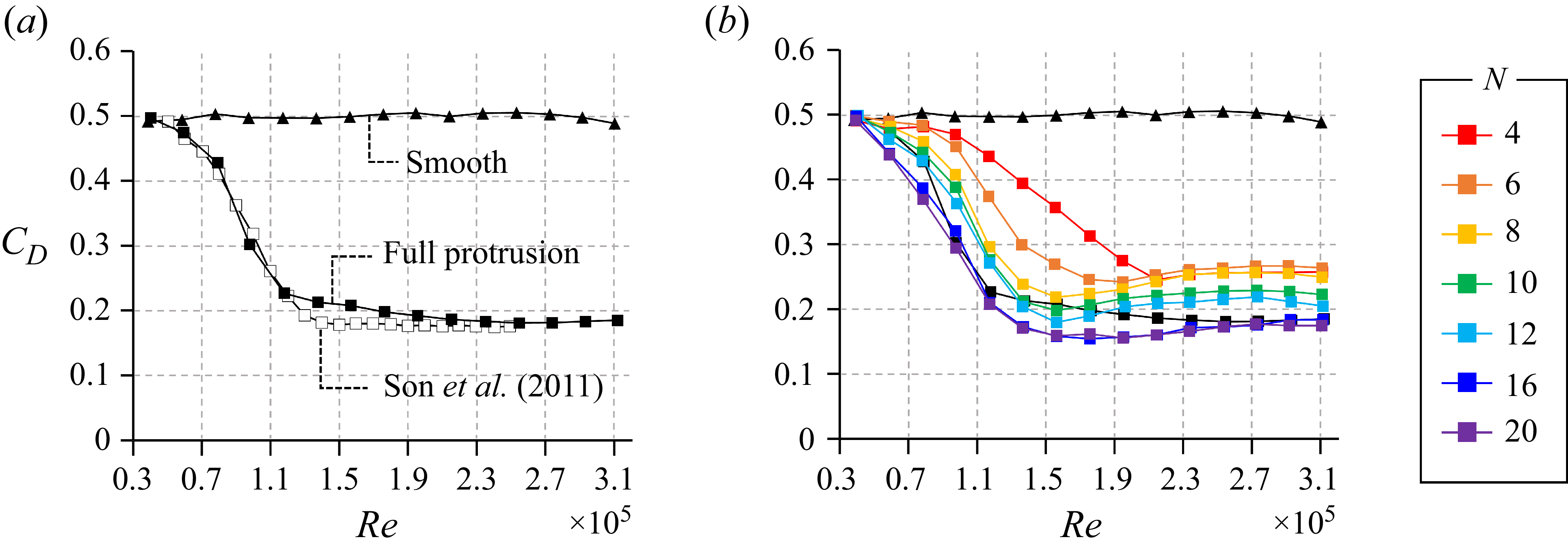


 Open access

