





1 Introduction
Mid-infrared (mid-IR) fiber lasers operating beyond 2.5 μm have attracted increasing interest in recent decades, due to their compact, robust architecture, high-power scalability and maintenance-free operation. These features have motivated their use in a wide range of high-end applications, including material processing[ Reference Frayssinous, Fortin, Bérubé, Fraser and Vallée1], gas sensing[ Reference Woodward, Majewski, Hudson and Jackson2], medical treatments[ Reference Selim, Lowery, Maredia and Zelickson3], optical communications[ Reference Su, Tian, Yu, Meng, Zheng, Jia, Xie, Wang, Zhu and Wang4] and defense systems[ Reference Bekman, van den Heuvel, van Putten and Schleijpen5]. Among different approaches, direct laser excitation with rare-earth-doped fluoride fibers offers a straightforward and efficient solution[ Reference Jackson and Jain6]. Unlike continuous-wave (CW) lasing, high-energy nanosecond pulses enable time-resolved sensing, higher throughput in laser machining and biological tissue ablation with minimized thermal effects. To produce these pulses, Q-switching and gain-switching are commonly employed techniques that have been widely used in Er3+- and Ho3+-doped fluoride fiber lasers within the 2.7–3 μm range[ Reference Jobin, Paradis, Aydin, Boilard, Fortin, Gauthier, Lemieux-Tanguay, Magnan-Saucier, Michaud, Mondor, Pleau, Talbot, Bernier and Vallée7]. For example, using an acousto-optic modulator (AOM) Q-switched Er3+-doped fluoride fiber oscillator, a record pulse energy of 560 μJ with a pulse width of 53 ns at 2.79 μm was achieved[ Reference Lamrini, Scholle, Schäfer, Ward, Francis, Farries, Sujecki, Benson, Seddon, Oladeji, Napier and Fuhrberg8]. Large-core Er3+-doped fluoride fiber amplifiers have recently scaled pulse energy to 1 millijoule (mJ) with a pulse width of 30 ns under near-diffraction-limited conditions[ Reference Bai, Zhou, Du, Cui and Galvanauskas9], and further boosted to 2 mJ with a narrower pulse width of 1.88 ns, albeit at the expense of beam quality (M 2 = 14.9)[ Reference Leonov, Perry-Auger, Karim, Zhang, Kraemer, Vallée and Bernier10], around 2.8 μm. At longer wavelengths beyond 3 μm, which overlap with the 3–5 μm atmospheric transmission window and encompass strong absorption bands of many polymers, lasing offers improved versatility for practical applications. The dual-wavelength (~976 nm + ~1976 nm) pumped Er3+-doped fluoride fiber platform, emitting in the 3.4–3.8 μm range, has been widely adopted. Using Q-switching and gain-switching, this system has produced nanosecond pulses with maximum energies of 9.4 μJ (578 ns) at 3.536 μm[ Reference Zhang, Tong, Meng and Cai11] and 6.54 μJ (30 ns) at 3.55 μm[ Reference Jobin, Fortin, Maes, Bernier and Vallée12], respectively. However, a spectral gap remains in the 3–3.4 μm region. This has prompted interest in two alternative rare-earth ions: Ho3+ (transition: 5F4,5S2→5F5)[ Reference Carbonnier, Többen and Unrau13, Reference Zhou, Luo, Wang, Liu and Electron14] and Dy3+ (transition: 6H13/2→6H15/2)[ Reference Majewski and Jackson15]. Compared to Ho3+, the Dy3+ transition – originating from the first excited state to the ground state – offers a lower quantum defect and a higher potential efficiency, along with a broad emission band of 2.7–3.5 μm[ Reference Wang, Luo, Tao, Wu, Lyu, Li and Liu16]. More importantly, the longer lifetime of its upper laser state (641 μs[ Reference Gomes, Librantz and Jackson17]) compared to Ho3+ (300 μs[ Reference Librantz, Jackson, Gomes, Ribeiro and Messaddeq18]) provides an advantage for generating high-energy pulses by storing more energy. Nonetheless, the maximum pulse energies from gain-switched and Q-switched Dy3+-doped fluoride fiber oscillators are relatively low: only 19.2 μJ (383–772 ns) at 3.24 μm[ Reference Jobin, Paradis, Fortin, Magnan-Saucier, Bernier and Vallée19] and 12 μJ (270 ns) at 3.1 μm[ Reference Woodward, Majewski, Macadam, Hu, Albrow-Owen, Hasan and Jackson20], respectively. Recently, Wang et al. [ Reference Wang, Zhu, Norwood and Peyghambarian21] introduced a new Er3+/Dy3+ co-doped fluoride fiber configuration that can be cladding-pumped using commercially available high-power laser diodes (LDs) of approximately 976 nm, which is promising for power and energy scaling. In this system, Er3+ ions absorb pump photons and subsequently transfer energy to Dy3+ ions, enabling lasing emission[ Reference Wang, Zhu, Mollaee, Zong and Peyghambarian22]. Following this work, output power of several watts with a slope efficiency approaching 20%[ Reference Zhao and Luo23] and watt-level wavelength tuning from 3.02 to 3.33 μm[ Reference Liu, Zhao, Luo, Chen, Zhang, Zhou, Li and Liu24] have been demonstrated, highlighting the significant potential of this architecture. On this platform, active Q-switching has produced high-energy nanosecond pulses at 2.94 μm with a pulse width of 41 ns and a maximum energy of 108 μJ[ Reference Zhao, Luo, Li and Liu25]. Under approximately 660 nm pumping, Q-switched pulses at 3.2 μm have also been achieved, with a maximum energy of 82 μJ and a pulse width of 520 ns[ Reference Zhao, Luo, Li and Liu26]. However, systems operating beyond 3 μm still lag behind state-of-the-art Er3+-doped fluoride fiber systems emitting at 2.7–2.8 μm. To date, there have been no reports on Er3+/Dy3+ co-doped fluoride fiber amplifiers or high-energy nanosecond pulse fluoride fiber amplifiers beyond 3 μm.
To address the energy gap between these systems, we develop a 980 nm LD bi-directionally pumped Er3+/Dy3+ co-doped fluoride fiber amplifier. This amplifier is seeded by an actively Q-switched Er3+/Dy3+ co-doped fluoride fiber oscillator operating at 1 kHz. Both the oscillator and amplifier have been extensively characterized. Consequently, high-energy nanosecond pulses with a record energy of 0.68 mJ and a pulse width of 132 ns have been achieved at 3.17 μm under single-transverse-mode operation. To the best of our knowledge, this work represents the first demonstration of an Er3+/Dy3+ co-doped fluoride fiber amplifier, and the first report of mJ-level nanosecond pulses beyond 3 μm from a fiber-based system.
2 Experimental setup
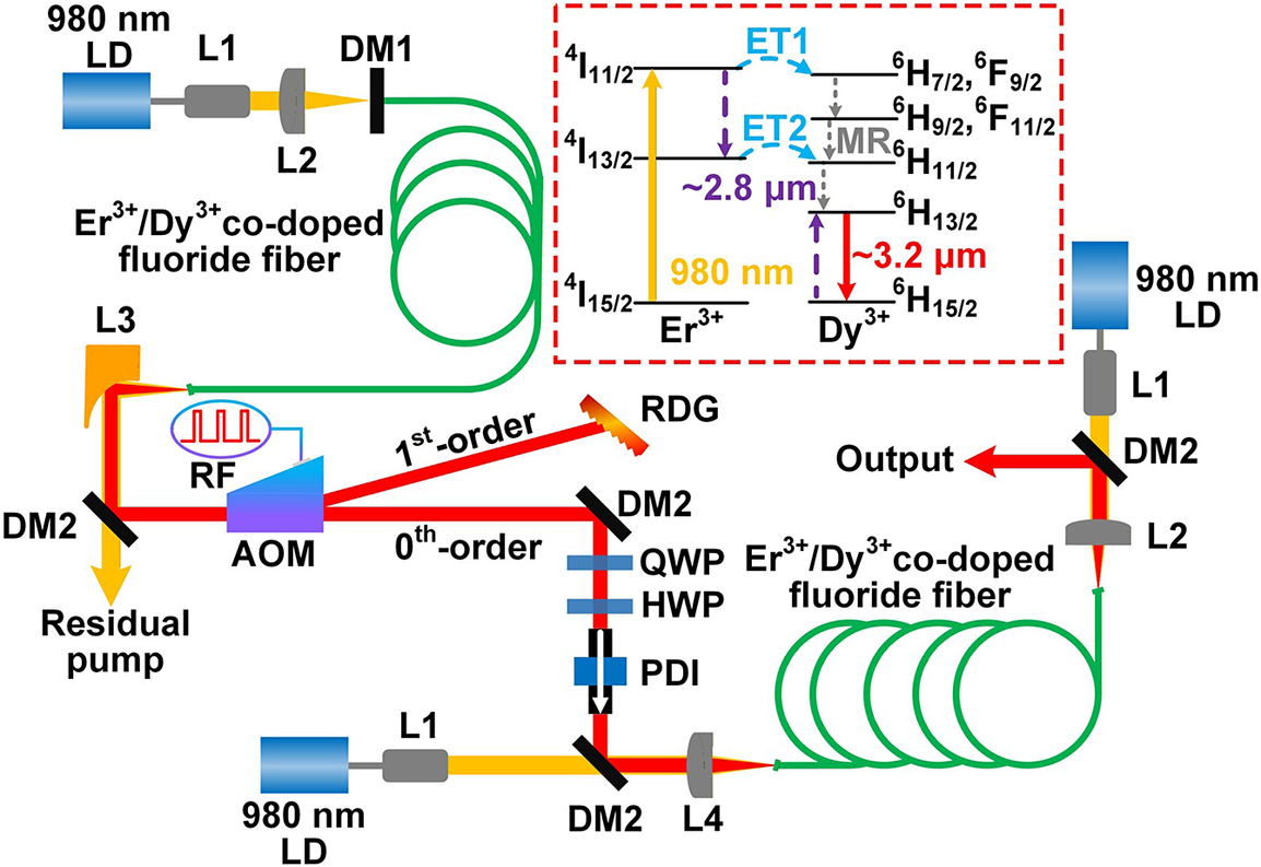
Figure 1 displays the experimental setup of the Er3+/Dy3+ co-doped fluoride fiber-based master oscillator power amplifier (MOPA) system, comprising an AOM actively Q-switched oscillator seed and a bi-directionally pumped single-pass amplifier.
Schematic setup of a master oscillator power amplifier (MOPA) based on a 980 nm diode-pumped Er3+/Dy3+ co-doped fluoride fiber. L1, collimator with 0.7–1.1 μm anti-reflection (AR) coating; L2, uncoated CaF2 plano-convex lens; L3, off-axis parabolic reflector with protected gold coating; L4, ZnSe aspheric lens with 1–5 μm AR coating; DM1 and DM2, two dichroic mirrors; RDG, ruled diffraction grating; QWP, quarter-wave plate; HWP, half-wave plate; PDI, polarization-dependent isolator. Inset: energy-level diagram with some relevant transitions. ET1 and ET2, two energy transfer processes; MR, multi-phonon relaxation.

The seed source is pumped by a commercial multi-mode 980 nm LD (BWT, China), pigtailed to a silica fiber with a 105 μm core diameter and a numerical aperture (NA) of 0.15, delivering 30 W of power. The gain medium is a 5.7 m long double-cladding 4%/0.25% (molar fractions) Er3+/Dy3+ co-doped fluoride fiber (Fiberlabs, Japan) with a core diameter of 19.5 μm and an NA of 0.13, and a circular inner cladding with a diameter of 250 μm and an NA of 0.5. Its cladding absorption coefficient at 980 nm was measured to be 1.32 dB/m, and the nominal cut-off wavelength is calculated to be 3.31 μm. Here, the 4%/0.25% Er3+/Dy3+ co-doping ratio is a compromise between energy transfer and concentration quenching for efficient lasing[ Reference Wang, Zhu, Norwood and Peyghambarian21]. The fiber body is coiled and placed directly on a passive aluminum plate with a curvature radius of 12 cm. The fiber tip, near the pump source, was perpendicularly cleaved and butted against a dichroic mirror (DM1), which is highly transmissive at 980 nm and reflective at 2.7–3.7 μm. The pump light is collimated by a lens (L1) with a focal length of 11 mm and then coupled into the fiber cladding via DM1 using L2 with a focal length of 20 mm. The coupling efficiency was measured to be 88% using a short segment of non-doped double-cladding fluoride fiber with similar geometry and NA. The other fiber tip was angle-cleaved at approximately 8o to suppress parasitic lasing. Lasing from this tip is collimated by L3, with a reflected focal length of 15 mm, and reflected by DM2 (highly transmissive at 980 nm and reflective at 2.7–3.7 μm at 45°) to filter out residual pump light. Subsequently, the beam is directed into a commercially available Ge AOM at its Bragg angle, identical to that used in our previous reports[ Reference Zhao, Luo, Li and Liu25, Reference Zhao, Luo, Li and Liu26]. The AOM has a maximum diffraction efficiency of 80% (measured at the laser wavelength), an insertion loss of 0.36 dB (2.5–5 μm anti-reflection (AR) coating on both facets of the AOM), an active aperture of 4 mm, a separation angle of 55 mrad between the first and zeroth orders and a rise time of less than or equal to 140 ns/mm. It is driven by a 68 MHz radio frequency (RF) source, which is modulated by a rectangular wave signal from a function generator with an adjustable duty cycle. The beam diameter on the AOM facet was measured to be 1.8 mm at the 1/e2 peak intensity using the knife-edge method. Following the optimized configuration described in Refs. [Reference Zhao, Luo, Li and Liu25,Reference Zhao, Luo, Li and Liu26], the zeroth-order light is used as the output. The first-order diffracted light is fed back into the cavity using a ruled diffraction grating (RDG; Thorlabs GR2550-30035) with a blaze wavelength of 3.5 μm in a Littrow configuration. The use of the RDG aims to suppress amplified spontaneous emission (ASE) around the laser wavelength and to stabilize the emission wavelength, thereby enabling stable Q-switching operation.
The amplifier is bi-directionally pumped by two high-power 980 nm LDs (BWT, China), each capable of 70 W power. The gain medium is a 7.2 m long double-cladding 4%/0.25% Er3+/Dy3+ co-doped fluoride fiber (Fiberlabs, Japan) with a core diameter of 22.8 μm and an NA of 0.13, and a circular inner clad with a diameter of 250 μm and an NA of 0.5. The measured clad absorption coefficient is 1.48 dB/m at 980 nm, and the nominal cut-off wavelength is 3.87 μm. Both fiber tips were angle-cleaved at 8°. Although a larger cleavage angle is generally required to suppress inner-cladding lasing, especially in high-gain double-cladding fluoride fiber (e.g., ~2.8 μm double-cladding heavily Er3+-doped fluoride fiber), this angle is sufficient for our Er3+/Dy3+ co-doped fluoride fiber with moderate gain to suppress approximately 3.2 μm parasitic lasing, as confirmed by subsequent experimental results. Furthermore, a cleavage angle that is too large will reduce the seed coupling efficiency, thereby diminishing the achievable pulse energy. The first 10 cm of each fiber end is held by our designed water-cooled aluminum clamp, which maintains a constant temperature of 18°C. The fiber body is coiled and placed on a water-cooled aluminum plate with a curvature radius of 14 cm. The backward pumping arrangement is the same as in the seed. DM2 is positioned between L1 and L2 to extract the amplified signal output. The forward pump coupling scheme consists of L1 and L4, where L4, highly transmissive at approximately 3.2 μm and 980 nm, has a focal length of 12.7 mm. It can provide a coupling efficiency of 90%. The signal from the seed is reflected by two DM2 and coupled into the fiber core of the amplifier with a coupling efficiency of 85%, as estimated using a singly Er3+-doped fluoride fiber (Fiberlabs, Japan) with a similar geometry and NA (i.e., 20 μm core diameter and 0.12 core NA). To prevent signal reflection back into the seed and destabilize its operation, a polarization-dependent isolator (PDI; Faraday Photonics, United States) is placed between the seed and amplifier, with a quarter-wave plate (QWP) and a half-wave plate (HWP) placed before it to maximize its transmissivity. The inset of Figure 1 illustrates the relevant energy-level diagram and transition processes of the system. Under 980 nm pumping, Er3+ ions are excited from the ground state 4I15/2 to the upper state 4I11/2. The energy is then transferred to Dy3+ ions via processes including energy transfer processes ET1, ET2, and approximately 2.8 μm emission (Er3+) and absorption (Dy3+), ultimately activating the 6H13/2→6H13/2 transition of Dy3+ ions to generate lasing emission around 3.2 μm[ Reference Zhao and Luo23].
In our experiment, the pulse energy was measured with a pyroelectric energy meter (Ophir, PE9-C). The total average power and ASE power were measured with a thermal power meter (Thorlabs, S405C). The pulse temporal characteristics and RF spectrum were recorded with a HgCdTe detector (VIGO, PCI-2TE-12) with a response time of less than or equal to 3 ns, connected to a 500 MHz digital oscilloscope and an 18 GHz electrical spectrum analyzer, respectively. The optical spectra were acquired with a spectrometer (Yokogawa, AQ6377) with a minimum resolution of 0.2 nm. The beam quality was evaluated with an infrared camera (Dataray, WinCamD-IR-BB).
3 Results and discussion
3.1 Seed performance
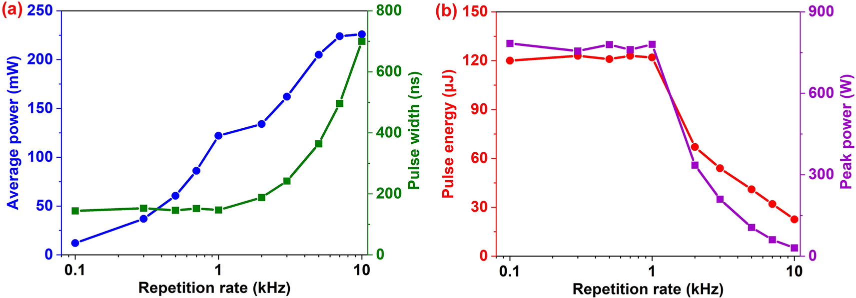
The performance of the actively Q-switched oscillator was first characterized. The RDG was carefully rotated and aligned to maximize output pulse energy, and then fixed in place. Figures 2(a) and 2(b) display the average power, pulse width, pulse energy and peak power as functions of the repetition rate from 0.1 to 10 kHz at a coupled pump power of 13.7 W. To maintain stable Q-switching operation across the repetition rate range, the AOM duty cycle was adjusted from 2% to 45%. Similar to previous reports on actively Q-switched Dy3+-doped and Er3+/Dy3+ co-doped fluoride fiber oscillators[ Reference Woodward, Majewski, Macadam, Hu, Albrow-Owen, Hasan and Jackson20, Reference Zhao, Luo, Li and Liu25, Reference Zhao, Luo, Li and Liu26], the average power initially rises and then saturates with increasing repetition rate. The pulse width remains nearly constant below 1 kHz but increases thereafter, aligning with the inverse of the upper-state lifetime. Conversely, both pulse energy and peak power drop sharply beyond 1 kHz. Notably, the decreased pulse energy at higher repetition rates results in weaker modulation of the net gain and, consequently, slower rise and decay of optical power[ Reference Zhang, Tong, Meng and Cai11]. At this pump power, a record pulse energy of 122 μJ was achieved at 1 kHz, with a pulse width of 147 ns and a peak power of 780 W, assuming a Gaussian pulse shape factor of 0.94. Further increasing the pump power led to multi-pulsing due to excessive energy accumulation in the gain medium, and an energy-saturation phenomenon was observed, as confirmed by a pyroelectric energy meter. To our knowledge, this is the highest energy reported to date from a nanosecond pulse fiber oscillator operating beyond 3 μm. The approximately 50% energy improvement over our previous report in this band[ Reference Zhao, Luo, Li and Liu26] is mainly due to using a larger core diameter and longer fiber, which improves energy storage. The corresponding average power is 122 mW, with a low slope efficiency of 1.6%. Besides losses introduced by the AOM, the low efficiency is mainly due to the low repetition rate (1 kHz), resulting in a significant loss of excited ions over the long time between pulses. When the modulation signal applied to the AOM was set to a high level (rated voltage: 2.5 V), which ensured maximum diffraction efficiency, the slope efficiency in CW operation mode increased significantly to 6.2%. Replacing the AOM and grating with a DM (80%/70% reflectivity) as the output coupler further improved the slope efficiency to 9%/13%. These results confirm our aforementioned explanation.
(a) Average power and pulse width and (b) pulse energy and peak power versus repetition rate at a coupled pump power of 13.7 W in the seed.
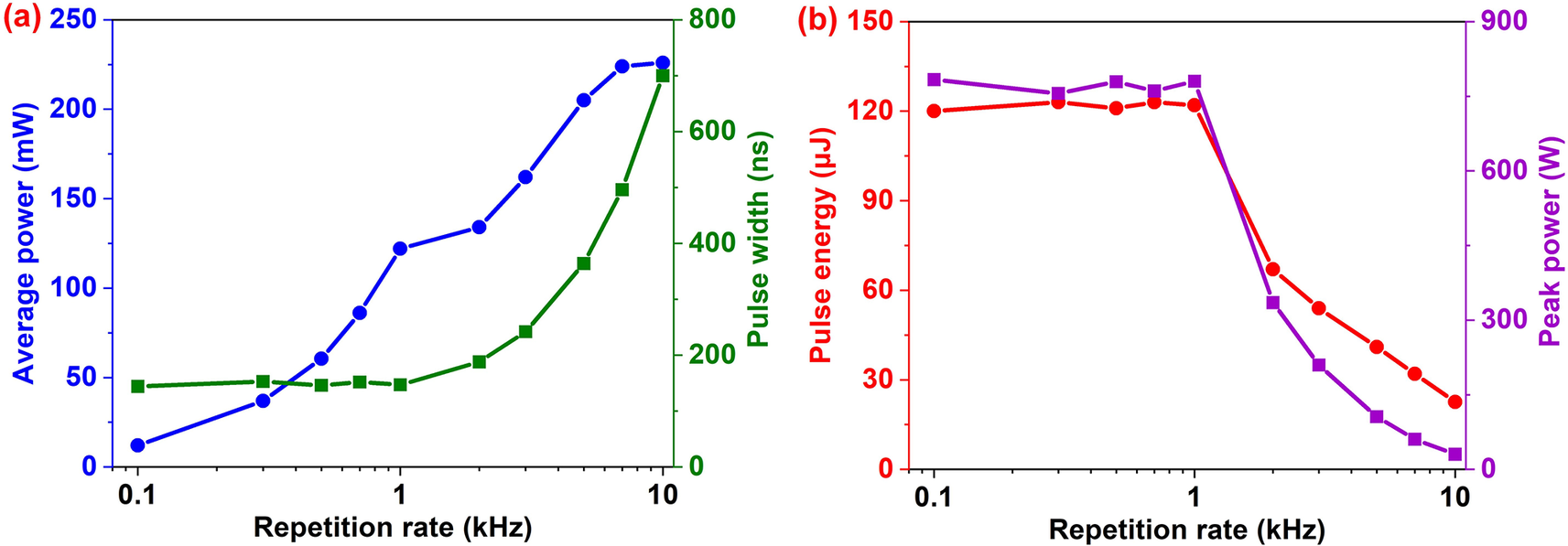
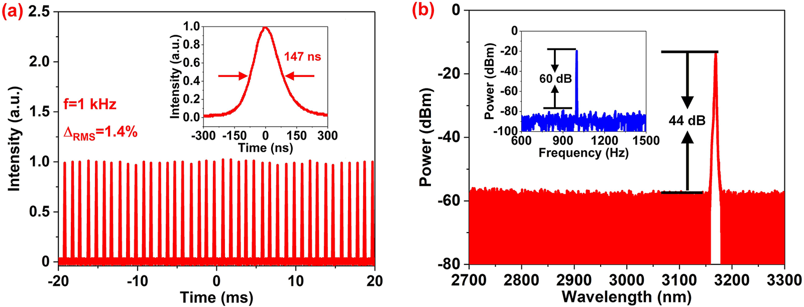
Figure 3(a) and its inset show the recorded pulse train and single pulse waveform, respectively. The pulse train exhibits excellent temporal stability, with a root mean square (RMS) amplitude fluctuation of only 1.4%. Its temporal profile is smooth, with no multi-pulsing behavior. The optical spectrum, shown in Figure 3(b), is centered at 3169 nm, within the fiber’s high-gain region. No prominent ASE components from Er3+ or Dy3+ ions are present. The high optical signal-to-noise ratio (SNR) of 44 dB, in part, indicates a small ASE fraction, attributable to effective filtering by the RDG. We used a thermal power meter and a pyroelectric energy meter to measure the total and pulsed average powers, respectively. The deviation of less than 0.5 mW further implies a significantly small ASE fraction. The RF spectrum, shown in the inset of Figure 3(b), exhibits a sharp peak at 1 kHz, matching the pulse repetition rate. Its high SNR of 60 dB confirms excellent pulse stability. The polarization properties of the output pulses were characterized using a film polarizer, revealing a polarization extinction ratio of approximately 13 dB. This indicates that the pulses are predominantly linearly polarized, consistent with the polarization-selective nature of the Ge AOM.
(a) Pulse train and single pulse waveform (inset) and (b) optical and RF (inset) spectra at a repetition rate of 1 kHz and a coupled pump power of 13.7 W in the seed.

3.2 Amplifier performance
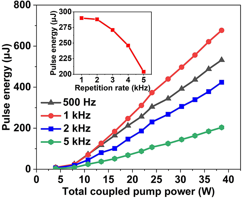
The amplifier performance was subsequently evaluated. Figure 4 shows the variation in pulse energy with total coupled pump power at different seed repetition rates. The forward-to-backward pump power ratio was maintained at approximately 1:1 to balance the thermal load on both fiber tips. Accounting for losses from DM2, QWP, HWP, PDI, L4 and imperfect coupling, the overall seed coupling efficiency, from the oscillator zeroth-order output port to the amplifier fiber core, was measured to be 45%. One can see that the pulse energy increases linearly with the total coupled pump power, with the best performance achieved at a 1 kHz seed repetition rate. Although the seed energy at 500 Hz was similar, increased energy loss due to spontaneous decay between pulses reduced the output energy, leading to strong ASE components of approximately 3.1 μm. At a higher repetition rate of 2 kHz, degraded performance is primarily attributed to the low seed energy, which weakens energy extraction. To verify this, the amplifier’s gain recovery time was roughly characterized by measuring output pulse energies at different seed repetition rates, with a fixed seed energy of 18.5 μJ, as shown in the inset of Figure 4. The estimated recovery time of approximately 500 μs is slightly less than the 641 μs upper-state lifetime, suggesting that similar pulse energy to 1 kHz could be achieved with the same seed energy. Accordingly, 1 kHz remains the optimal seed repetition rate. At a total coupled pump power of 38.6 W, a record pulse energy of 0.68 mJ was achieved. To our knowledge, this is the first demonstration of mJ-level nanosecond pulses from a fiber-based system operating beyond 3 μm, representing at least one order of magnitude increment over previous fiber lasers in this region[ Reference Jobin, Paradis, Fortin, Magnan-Saucier, Bernier and Vallée19, Reference Woodward, Majewski, Macadam, Hu, Albrow-Owen, Hasan and Jackson20, Reference Zhao, Luo, Li and Liu26– Reference Wang, Luo, Wu, Li and Liu30]. The amplification gain of 10.9 dB is harmonious with the recently reported CW singly Dy3+-doped fluoride fiber amplifier (~10 dB)[ Reference Michaud, Boilard, Vallée and Bernier31]. Nevertheless, the Er3+/Dy3+ co-doped system offers superior scalability for high-power operation, owing to its cladding-pumped design, which reduces thermal load compared to core-pumped setups. No energy-saturation phenomenon was observed, suggesting further energy scaling is possible by increasing pump power. However, higher energies could damage the rear fiber tip. To further increase the output energy, a feasible solution is to add another amplification stage with a larger-core fiber.
Pulse energy versus total coupled pump power at different seed repetition rates, with the seed energy coupled into the amplifier maximized at each repetition rate (i.e., 54.5 μJ at 500 Hz, 55 μJ at 1 kHz, 30 μJ at 2 kHz and 18.5 μJ at 5 kHz). Inset: pulse energy versus seed repetition rate at a total coupled pump power of 38.6 W, with the seed energy coupled into the amplifier held at 18.5 μJ.

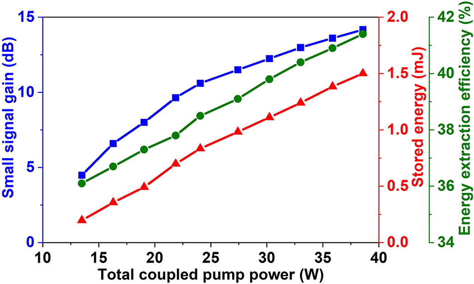
The stored energy of our Er3+/Dy3+ co-doped fluoride fiber amplifier was also evaluated using the classical Frantz–Nodvik model[ Reference Frantz and Nodvik32, Reference Siegman33], recently applied to characterize a 2.8 μm Er3+-doped fluoride fiber amplifier[ Reference Du, Bai, Cui, Chen and Galvanauskas34]. Figure 5 shows the variation in small-signal gain, stored energy and energy extraction efficiency with the total coupled pump power. One observes that the small-signal gain increases rapidly at first and then slightly saturates. Throughout this process, the seed power coupled into the amplifier remained at about 5 mW (pulse width: 147 ns, repetition rate: 1 kHz), which was verified to be within the small-signal regime. All ASE components were excluded from the measurements. As the pump power increases from 13.5 to 38.6 W, the stored energy rises almost linearly from 0.2 to 1.5 mJ, while the energy extraction efficiency gradually grows from 36.1% to 41.4%. Despite the large stored energy afforded by the long fiber, the extraction efficiency is only about half of that of the previous 2.8 μm Er3+-doped fluoride fiber amplifier (~80%)[ Reference Du, Bai, Cui, Chen and Galvanauskas34]. The main reason is that the seed pulse energy coupled into our amplifier is much lower than the fiber saturation energy (estimated to be around 700 μJ). This suggests that, in principle, a pulse energy beyond 1 mJ could be achieved by increasing the seed energy, assuming fiber tip damage is not an issue, and underscores the importance of adding a pre-amplifier to enhance energy extraction at this stage.
Measured small-signal gain, stored energy and energy extraction efficiency of the Er3+/Dy3+ co-doped fluoride fiber amplifier versus total coupled pump power, with the seed repetition rate and energy coupled into the amplifier at 1 kHz and 55 μJ, respectively.

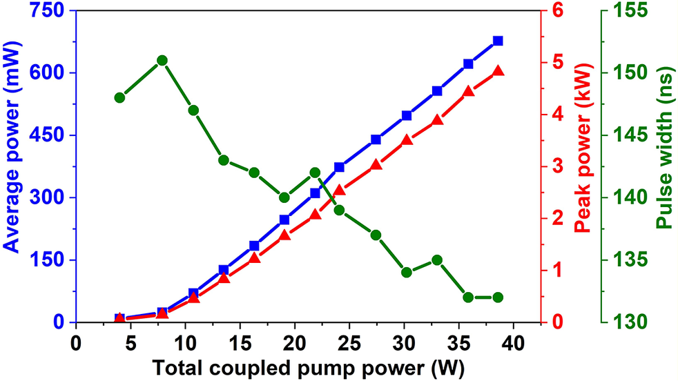
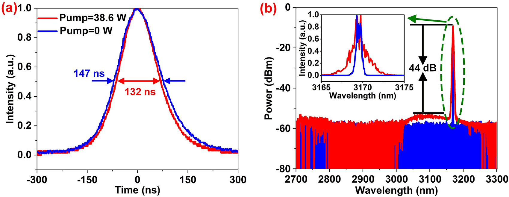
Figure 6 displays the corresponding variations in average power, pulse width and peak power as a function of the total coupled pump power at a seed repetition rate of 1 kHz. The average power grows linearly with a low slope efficiency of 2.2%. Such low efficiency is primarily due to poor energy extraction and a low repetition rate, leading to a significant loss of excited ions over a prolonged period. The pulse width clearly narrows, primarily due to gain saturation, with the output pulse energy approaching the fiber saturation energy of around 700 μJ. This is evidenced by the faster pulse front compared to the seed, as shown in Figure 7(a). In addition, nonlinear spectral broadening, as shown in the inset of Figure 7(b), partly contributes to this narrowing. It is worth noting that the seed optical spectrum after passing through the amplifier without pump power is obviously narrowed, likely due to re-absorption of Dy3+ ions at this wavelength. The peak power follows a similar trend to the average power, reaching a maximum of 4.8 kW with a pulse width of 132 ns at a maximum total coupled pump power of 38.6 W. Importantly, no parasitic lasing at approximately 2.8 μm or approximately 3.1 μm was detected, as shown in Figure 7(b), even at the maximum pump power, aside from ASE components with an average power of about 2 mW (approximately 0.3% of the total average power), which indicate their minor influence on the amplifier output. The high optical SNR of 44 dB further highlights the high quality of the amplified pulse signal.
Average power, pulse width and peak power versus total coupled pump power, with the seed repetition rate and energy coupled into the amplifier at 1 kHz and 55 μJ, respectively.

(a) Temporal pulse waveforms and (b) optical spectra (inset: zoomed linear scale optical spectra) at total coupled pump powers of 0 and 38.6 W, with the seed repetition rate and energy coupled into the amplifier at 1 kHz and 55 μJ, respectively.

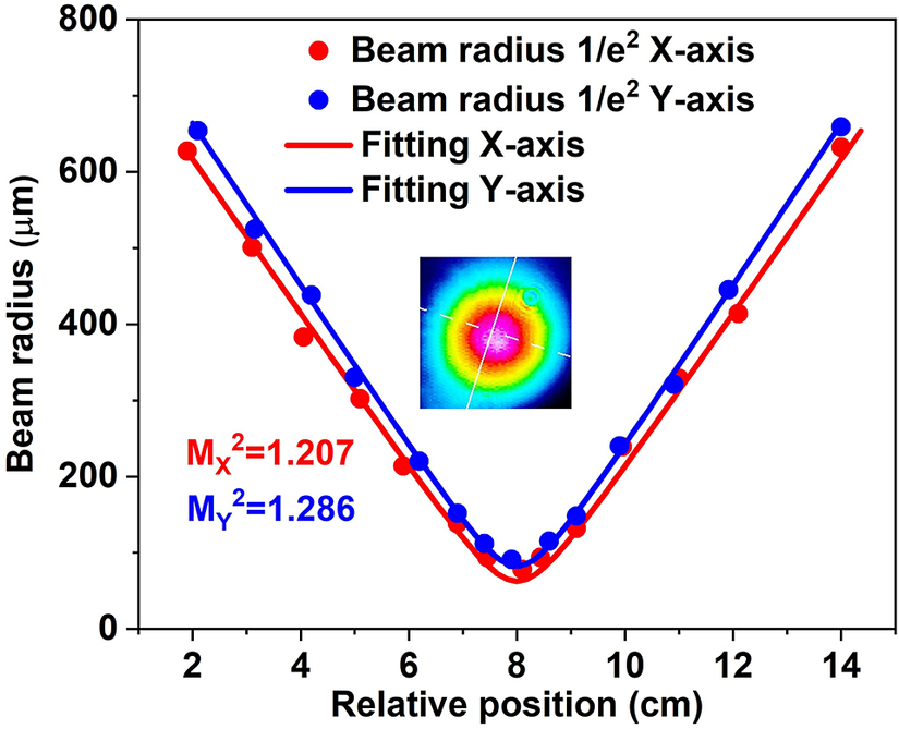
At maximum pump power, the output beam quality was assessed by focusing the beam with a CaF2 plano-convex lens featuring a 75 mm focal length, aligned with the infrared camera axis. Figure 8 and its inset show the measured beam radii along the X- and Y-axes as a function of the relative position Z and a captured image of the collimated output beam, respectively. The beam profile displays a symmetric Gaussian distribution, with calculated M 2 values of 1.207 in the X-direction and 1.286 in the Y-direction. These results confirm single-transverse-mode operation of the amplifier. This behavior arises from the fiber’s intrinsic single-mode excitation despite its few-mode nature, achieved by maximizing output energy through moderate seed coupling aligned in our setup. Although we did not use a standard single-mode fiber method to evaluate beam quality, as demonstrated in Ref. [Reference Du, Bai, Cui, Chen and Galvanauskas34], achieving single-mode excitation in our case is relatively easier. This is because the fiber normalized frequency (2.936) is only slightly above the single-mode cut-off frequency (2.405).
Beam quality measurement (M 2) for the X- and Y-axes, and an image of the collimated output beam (inset) at a total coupled pump power of 38.6 W, with the seed repetition rate and energy coupled into the amplifier at 1 kHz and 55 μJ, respectively.

4 Conclusions
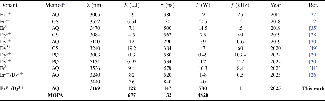
In summary, we have experimentally demonstrated, to the best of our knowledge for the first time, a mid-IR fiber MOPA system based on a 980 nm diode-pumped Er3+/Dy3+ co-doped fluoride fiber, capable of producing mJ-level nanosecond pulses beyond 3 μm. The seed source is an AOM actively Q-switched Er3+/Dy3+ co-doped fluoride fiber oscillator that produces stable nanosecond pulses at 3.17 μm. Operating at a 1 kHz repetition rate, the oscillator delivers 122 μJ energy pulses, with a pulse width of 147 ns and a peak power of 780 W. When these seed pulses are amplified in a bi-directionally pumped Er3+/Dy3+ co-doped fluoride fiber amplifier, the pulse energy is significantly boosted to 0.68 mJ, with a slightly reduced pulse width of 132 ns and a peak power of 4.8 kW. The amplifier maintains single-transverse-mode operation, with measured beam quality factors of MX 2 = 1.207 and MY 2 = 1.286. Further energy scaling is primarily limited by damage to the amplifier output fiber tip. Nonetheless, this work is the first report of mJ-level nanosecond pulse generation beyond 3 μm from a fiber-based system (see Table 1). Further improvement in pulse energy is expected by employing multi-stage, larger-core Er3+/Dy3+ co-doped fluoride fiber amplifiers.
Performance comparison of nanosecond pulsed fiber laser systems in the spectral region of more than 3 μm.

a GS, gain-switching; PQ, passive Q-switching; AQ, active Q-switching; λ, wavelength; E, pulse energy; τ, pulse width; P, peak power; f, repetition rate.
Acknowledgements
This work was supported by the National Natural Science Foundation of China (Grant Nos. 62475035 and 62575051), the Guangdong Basic and Applied Basic Research Foundation (Grant Nos. 2024A1515110015 and 2026A1515010146), the Equipment Preresearch Joint Fund of the Ministry of Education (Grant No. 8091B042228), the Science and Technology Project of Sichuan Province (Grant Nos. 2023NSFSC1964 and 203NSFSC0033) and the Stability Support Special Project of the Southwest Institute of Technical Physics (Grant No. 2024-WZ-9).

 Open access

