


1. Introduction
Among magnetic confinement fusion concepts, stellarators are arguably the second most advanced, after tokamaks. By forgoing axisymmetry, stellarators can create rotational transform (twist) of the toroidal magnetic field without requiring a large plasma current. However, modern optimised stellarators (like Wendelstein 7-X (W7-X) or the helically symmetric experiment (HSX)) typically use irregular, non-planar coils to generate the carefully designed magnetic configurations that achieve the necessary particle confinement. These coils present a considerable engineering challenge due to their high complexity and low tolerances (Riße Reference Riße2009; Strykowsky et al. Reference Strykowsky, Brown, Chrzanowski, Cole, Heitzenroeder, Neilson, Rej and Viol2009).
ReBCO (rare-earth barium copper oxide) superconductors offer promising characteristics for the high-field magnets required for future fusion reactors. Compared with conventional low-temperature superconductors such as NbTi and Nb $_3$
Sn, ReBCO exhibits enhanced tolerance for high magnetic field strength and can operate at higher temperatures. While the transition temperature of ReBCO is typically around 90 K, high-field magnets using ReBCO are mostly operated around 20 K to utilise the increased in-field performance. This enables more efficient cooling of the coils and a smaller device size compared with the 4 K operating point of low-temperature superconductors. ReBCO superconductors are typically deposited as thin (
$_3$
Sn, ReBCO exhibits enhanced tolerance for high magnetic field strength and can operate at higher temperatures. While the transition temperature of ReBCO is typically around 90 K, high-field magnets using ReBCO are mostly operated around 20 K to utilise the increased in-field performance. This enables more efficient cooling of the coils and a smaller device size compared with the 4 K operating point of low-temperature superconductors. ReBCO superconductors are typically deposited as thin ( ${\sim} 4\,\mu$
m) ceramic layers onto Hastelloy bands or ‘tapes’ (100
${\sim} 4\,\mu$
m) ceramic layers onto Hastelloy bands or ‘tapes’ (100 $\mu$
m thick and 3–12 mm wide) to render them usable. However, the brittleness of the ceramic layers still poses a challenge, particularly in the context of the intricate, non-planar configurations of modular stellarator coils. Addressing this challenge involves reducing strain to ensure compatibility with ReBCO by adjusting the tape orientation along the coil.
$\mu$
m thick and 3–12 mm wide) to render them usable. However, the brittleness of the ceramic layers still poses a challenge, particularly in the context of the intricate, non-planar configurations of modular stellarator coils. Addressing this challenge involves reducing strain to ensure compatibility with ReBCO by adjusting the tape orientation along the coil.
Three different ways to deform a superconducting tape: (a) normal and (b) binormal curvature, as well as (c) torsion. The vector triplets indicate the tangent ( $\mathbf T$
), normal (
$\mathbf T$
), normal ( $\mathbf N$
) and binormal (
$\mathbf N$
) and binormal ( $\mathbf B$
) directions, as defined by the tape orientation.
$\mathbf B$
) directions, as defined by the tape orientation.

There are three ways to apply strain to a tape, as illustrated in figure 1. The quasi two-dimensional nature results in a preferred direction of bending. Bending the tape around its binormal axis (‘easy-way bending’ or ‘normal curvature’) strains the ReBCO layer much less than bending around the normal axis (‘hard-way bending’ or ‘binormal curvature’). In addition to the two forms of bending, the tape is also put under strain by twisting – a rotation of the tape frame around its tangent axis (‘torsion’). We assume a critical strain of 0.2 %–0.4 % throughout this paper. While Nickel et al. (Reference Nickel, Fietz, Weiss and Wolf2021) found no significant degradation of the critical current below 0.4 % strain, the EPOS and CSX projects choose a more conservative 0.2 % strain as the acceptable limit. This provides a safety margin for the assembly process, as the strain during winding may exceed that of the finished coil (e.g. a handling error led to a defect in one of the coils built by Huslage et al. (Reference Huslage, Kulla, Lobsien, Schuler and Stenson2024)).
Optimisation of the tape winding path orientation involves trading off hard-way bending and torsion to distribute these along a coil, enabling all parts of the coil to stay within strain limits. Previous efforts by Paz-Soldan (Reference Paz-Soldan2020) and Huslage et al. (Reference Huslage, Kulla, Lobsien, Schuler and Stenson2024) optimised the orientation of a tape stack wound into the shape of previously defined coils. However, it is not always possible to find a ReBCO-compatible winding path for a given filamentary coil shape at the desired coil size. Especially for those cases, but also benefiting the more general goal of decreasing stellarator coil complexity, we have now made it possible to include the strain penalty in the optimisation process that defines the filamentary coils in the first place.
This paper is structured as follows. Section 2 introduces the penalty functions to optimise for strain on non-planar, ReBCO coils, along with a metric for minimising full rotations of the tape frame used in CSX coil optimisation. Section 3 discusses implementation into the stellarator optimisation framework SIMSOPT (Landreman et al. Reference Landreman, Medasani, Wechsung, Giuliani, Jorge and Zhu2021) and shows benchmarks against previous methodologies. Sections 4 and 5 show strain-optimised coil sets for the small stellarators EPOS and CSX, respectively, and § 6 shows the application of the strain optimisation on a reactor-relevant winding pack. Section 7 summarises the results of this paper and gives an outlook on future work.
2. Strain on superconducting ReBCO coils
In stellarator optimisation, coils are often represented as filamentary curves (e.g. Zhu et al. (Reference Zhu, Hudson, Song and Wan2018)). The shape of these curves is typically optimised to fit the magnetic field on the boundary surface of a given magnetohydrodynamic equilibrium. To calculate and optimise for the strain experienced by a (quasi-) two-dimensional (2-D) ReBCO tape following the curve, we need to add the orientation of the tape (as knwon as ‘winding angle’) to the filamentary representation. We do this by defining a local frame at each point on the curve – i.e. tangent, normal and binormal vectors (which are associated with the tape orientation, as shown in figure 1).
In SIMSOPT, two such frames are already implemented. For a twice-differentiable, three-dimensional curve $\boldsymbol {\Gamma }$
, there exists a right-handed coordinate system called the Frenet frame. It consists of the tangent (
$\boldsymbol {\Gamma }$
, there exists a right-handed coordinate system called the Frenet frame. It consists of the tangent ( $\mathbf T$
), normal (
$\mathbf T$
), normal ( $\mathbf N$
) and binormal (
$\mathbf N$
) and binormal ( $\mathbf B$
) unit vectors which are defined as
$\mathbf B$
) unit vectors which are defined as
 \begin{align} \mathbf T &= \frac {\boldsymbol \Gamma '}{\|\boldsymbol \Gamma '\|}, \end{align}
 \begin{align} \mathbf {N} &= \frac {\mathbf T'}{\|\mathbf T'\|}, \end{align}
 \begin{align} \mathbf {B} &= \mathbf T\times \mathbf N, \end{align}
where the prime indicates the derivative with respect to the arc length. The normal vector of the Frenet frame tends to oscillate strongly if the coil is locally straight ( $\|\mathbf T'\|\approx 0$
). To avoid this behaviour, Singh et al. (Reference Singh, Kruger, Bader, Zhu, Hudson and Anderson2020) implemented the centroid frame, where the normal vector is calculated as
$\|\mathbf T'\|\approx 0$
). To avoid this behaviour, Singh et al. (Reference Singh, Kruger, Bader, Zhu, Hudson and Anderson2020) implemented the centroid frame, where the normal vector is calculated as
 \begin{align} \mathbf N = \frac {\boldsymbol {\delta }-(\boldsymbol {\delta }\cdot \mathbf T)\mathbf T}{\|\boldsymbol {\delta }-(\boldsymbol {\delta }\cdot \mathbf T)\mathbf T\|},\quad \boldsymbol {\delta } = \boldsymbol {\Gamma } - \mathbf X_{c,0}. \end{align}
This frame defines $\boldsymbol \delta$
as the vector from the centre of the curve using
$\boldsymbol \delta$
as the vector from the centre of the curve using $\boldsymbol {X}_{c,0}$
, which is the zeroth-order cosine Fourier coefficient of the curve. Here,
$\boldsymbol {X}_{c,0}$
, which is the zeroth-order cosine Fourier coefficient of the curve. Here, $\boldsymbol {X}_{c,0}$
represents the centre of mass of the coil. The normal vector is the normalised part of
$\boldsymbol {X}_{c,0}$
represents the centre of mass of the coil. The normal vector is the normalised part of $\delta$
orthogonal to
$\delta$
orthogonal to $\mathbf T$
.
$\mathbf T$
.
(a) Torsion and (b) binormal curvature for the Frenet (orange) and the centroid (blue) frames along the central filament of W7-X coil 1, where $l$
is the normalised arc length. The Frenet frame has no binormal curvature but high, localised torsion. The centroid frame has more regular torsion, but has strong binormal curvature.
$l$
is the normalised arc length. The Frenet frame has no binormal curvature but high, localised torsion. The centroid frame has more regular torsion, but has strong binormal curvature.
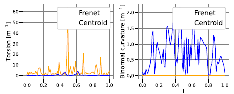
Figure 2 illustrates the difference between these two frames: torsion (panel a) and binormal curvature (panel b) are plotted versus the normalised arc length $l$
along the coil. The Frenet frame (orange) exhibits strong torsion, while retaining zero binormal curvature. The centroid (blue) frame shows considerably less torsion, but high binormal curvature. Both frames typically require optimisation to be compatible with ReBCO. Therefore, after having defined
$l$
along the coil. The Frenet frame (orange) exhibits strong torsion, while retaining zero binormal curvature. The centroid (blue) frame shows considerably less torsion, but high binormal curvature. Both frames typically require optimisation to be compatible with ReBCO. Therefore, after having defined $(\mathbf T, \mathbf N, \mathbf B)$
as a frame to
$(\mathbf T, \mathbf N, \mathbf B)$
as a frame to $\boldsymbol \Gamma$
(either Frenet or centroid), we now define another frame rotated by an angle
$\boldsymbol \Gamma$
(either Frenet or centroid), we now define another frame rotated by an angle $\alpha$
in the
$\alpha$
in the $\mathbf {N}{-}\mathbf {B}$
plane:
$\mathbf {N}{-}\mathbf {B}$
plane:
 \begin{align} \tilde {\mathbf T}&=\mathbf T,\end{align}
 \begin{align} \tilde {\mathbf N}&=\mathbf N \cos {\alpha } + \mathbf B \sin {\alpha }, \end{align}
 \begin{align} \tilde {\mathbf B}&=\mathbf B \cos {\alpha } - \mathbf N \sin {\alpha }. \end{align}
Like the vectors $\mathbf T$
,
$\mathbf T$
, $\mathbf N$
and
$\mathbf N$
and $\mathbf B$
, the angle
$\mathbf B$
, the angle $\alpha$
varies along the curve. Unlike those vectors, which are derived from the filamentary curve,
$\alpha$
varies along the curve. Unlike those vectors, which are derived from the filamentary curve, $\alpha$
is an independent quantity that can also be optimised separately from the curve – e.g. to minimise strain on the tape. For the rotated frame, the normal (
$\alpha$
is an independent quantity that can also be optimised separately from the curve – e.g. to minimise strain on the tape. For the rotated frame, the normal ( $\kappa$
) and binormal (
$\kappa$
) and binormal ( $\eta$
) curvatures and the torsion (
$\eta$
) curvatures and the torsion ( $\tau$
) are expressed as dot products of the frame vectors and their derivatives along the curve:
$\tau$
) are expressed as dot products of the frame vectors and their derivatives along the curve:
 \begin{align} \kappa &=\frac {\tilde {\mathbf N} \cdot \tilde {\mathbf T}^{\prime }}{\|\boldsymbol \Gamma '\|}, \end{align}
 \begin{align} \eta &=\frac {\tilde {\mathbf B} \cdot \tilde {\mathbf T}^{\prime }}{\|\boldsymbol \Gamma '\|}, \end{align}
 \begin{align} \tau &=\frac {\tilde {\mathbf B} \cdot \tilde {\mathbf N}^{\prime }}{\|\boldsymbol \Gamma '\|}. \end{align}
All quantities are normalised to $\|\boldsymbol \Gamma '\|$
to account for the curve not being arc length parametrised. It is important to note that the torsion and curvatures computed here are identical to the torsion and curvature defined for a curve in the Frenet frame. The above expressions are dependent on the rotated frame and do not fulfil the Frenet–Serret equations.
$\|\boldsymbol \Gamma '\|$
to account for the curve not being arc length parametrised. It is important to note that the torsion and curvatures computed here are identical to the torsion and curvature defined for a curve in the Frenet frame. The above expressions are dependent on the rotated frame and do not fulfil the Frenet–Serret equations.
For a specified critical strain $\epsilon _{{crit}}$
, and a superconducting tape of width
$\epsilon _{{crit}}$
, and a superconducting tape of width $w$
and thickness
$w$
and thickness $h$
, the upper bounds for
$h$
, the upper bounds for $\kappa, \eta, \tau$
are
$\kappa, \eta, \tau$
are
 \begin{align} \kappa _{{crit}}&=\frac {2\epsilon _{{crit}}}{h}, \end{align}
 \begin{align} \eta _{{crit}}&=\frac {2\epsilon _{{crit}}}{w}, \end{align}
 \begin{align} \tau _{{crit}}&=\frac {\sqrt {12\epsilon _{{crit}}}}{w}. \end{align}
We can safely ignore the strain from normal bending, because $\kappa _{{crit}}/\eta _{{crit}}=w/h\ll 1$
. Typical values are
$\kappa _{{crit}}/\eta _{{crit}}=w/h\ll 1$
. Typical values are $h\approx 100\,\mu \text {m},\ w=3{-}12\,\text {mm}$
and
$h\approx 100\,\mu \text {m},\ w=3{-}12\,\text {mm}$
and $\epsilon _{{crit}}=0.2\,\%{-}0.4\,\%$
. For 0.2 % critical strain and 3 mm wide tape,
$\epsilon _{{crit}}=0.2\,\%{-}0.4\,\%$
. For 0.2 % critical strain and 3 mm wide tape, $\eta _{{crit}}$
= 1.3/m and
$\eta _{{crit}}$
= 1.3/m and $\tau _{{crit}}$
= 52/m. We use the torsional strain (
$\tau _{{crit}}$
= 52/m. We use the torsional strain ( $\epsilon _{{tor}}=\tau ^2 w^2/12$
) and hard-way bending strain (
$\epsilon _{{tor}}=\tau ^2 w^2/12$
) and hard-way bending strain ( $\epsilon _{{bend}}=w\eta /2$
) to implement LP norm penalty functions for optimisation as follows:
$\epsilon _{{bend}}=w\eta /2$
) to implement LP norm penalty functions for optimisation as follows:
 \begin{equation} \begin{aligned} J_{{tor}}&=\frac {1}{p}\int _{\boldsymbol \Gamma }{\rm d}l\,\text {max}(\epsilon _{{tor}} - \epsilon _{{crit}}, 0)^p, \\ J_{{bend}}&=\frac {1}{p}\int _{\boldsymbol \Gamma }{\rm d}l\,\text {max}(\epsilon _{{bend}} - \epsilon _{{crit}}, 0)^p . \end{aligned} \end{equation}
Equation (2.14) gives a smooth metric to compute the relevant strains along a coil. The parameter $p$
(2 by default) can be chosen to more strongly penalise high peaks in the metric.
$p$
(2 by default) can be chosen to more strongly penalise high peaks in the metric.
In addition to the strain, we penalise the angle of rotation between the tape frame and centroid frame, defined as $\alpha$
in (2.5) and denoted here by
$\alpha$
in (2.5) and denoted here by $\alpha _{{centroid}}$
. This is motivated by a desire to reduce the net winding of the tape frame, which complicates the winding process. An LP norm penalty function for this is defined as
$\alpha _{{centroid}}$
. This is motivated by a desire to reduce the net winding of the tape frame, which complicates the winding process. An LP norm penalty function for this is defined as
 \begin{align} J_{{twist}} = \left (\frac {\int _{\Gamma } {\rm d}l \, \alpha _{{centroid}}^p}{\int _{\Gamma } {\rm d}l } \right )^{1/p}. \end{align}
Note that the implementation of this objective enables $\alpha _{{centroid}}$
to be evaluated in any frame, not necessarily one defined with respect to the centroid frame.
$\alpha _{{centroid}}$
to be evaluated in any frame, not necessarily one defined with respect to the centroid frame.
3. Implementation into SIMSOPT
SIMSOPT is a framework for stellarator optimisation based on python and C++. Among its capabilities are the ability to define geometric quantities, such as boundary surfaces of stellarator equilibria, filamentary coil shapes and the HTS tape orientation. These geometric quantities can be optimised using standard routines from scipy (Virtanen et al. Reference Virtanen2020). An overview of the code can be found from Landreman et al. (Reference Landreman, Medasani, Wechsung, Giuliani, Jorge and Zhu2021).
Coils are implemented as one-dimensional current-carrying filaments. To incorporate the rotation of the winding pack, we implemented the class FramedCurve that adds an angle to the filamentary coil that represents the rotation of a given initial frame in the $\mathbf {N}{-}\mathbf {B}$
plane as described in (2.5). The curve as well as the angle are described by a Fourier series. The metrics for strain from torsion and binormal curvature defined in (2.14) are implemented as optimisable objects that can be used in a penalty function for coil optimisation. We observed that
$\mathbf {N}{-}\mathbf {B}$
plane as described in (2.5). The curve as well as the angle are described by a Fourier series. The metrics for strain from torsion and binormal curvature defined in (2.14) are implemented as optimisable objects that can be used in a penalty function for coil optimisation. We observed that ${\sim} 500$
quadrature points were typically sufficient to describe the strain with single digit machine precision along the coils we investigated during this work.
${\sim} 500$
quadrature points were typically sufficient to describe the strain with single digit machine precision along the coils we investigated during this work.
We validated our code against the Matlab implementation used by Paz-Soldan (Reference Paz-Soldan2020) for coil 1 of the HSX stellarator. The two codes produced results for the torsional and binormal curvature strain that are in excellent agreement with each other. This is shown in figure 3.
A comparison of torsional strain values for HSX coil 1, optimised with SIMSOPT (blue dashed lines) and MATLAB implementation (orange lines, (Paz-Soldan Reference Paz-Soldan2020)), initialised from either (a) the centroid frame or (b) Frenet frame.

However, not all filamentary coils are consistent with meeting strain requirements at the desired size, making it necessary to include strain in the filamentary optimisation. Previously, strain optimisation was only performed on the already optimised filamentary coil to determine the orientation of the winding pack. We now optimised the shape of the coil in combination with the winding angle by including all degrees of freedom (DOFs) of the framed curve class into a coil optimisation function. This allows for better optimised coils with lower strain while achieving a given target magnetic field. By changing the weight on the strain penalty term, it is possible to make a trade-off between field accuracy and non-planarity of the coils. A high weight on the strain penalty results in increasingly more planar coils at the cost of increased field error. Note that the strain penalties from (2.14) both vanish for a planar curve with the normal vector pointing radially outwards.
The effect of the strain penalty on the shape of coils is similar to the impact of the regularisation term used in the coil optimisation code REGCOIL. There, a current potential on a winding surface is optimised to fit a given magnetic equilibrium. The complexity of this surface can be regulated by a single parameter $\lambda$
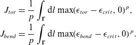
. Details on this code can be found from Landreman (Reference Landreman2017). The regularizing effect of the strain penalty is illustrated in figure 4 showing the normal field against the peak strain along the coils for 169 coil sets optimized to fit an EPOS candidate equilibrium. There is a trade-off between field accuracy and the planarity of the coils.
$\lambda$
. Details on this code can be found from Landreman (Reference Landreman2017). The regularizing effect of the strain penalty is illustrated in figure 4 showing the normal field against the peak strain along the coils for 169 coil sets optimized to fit an EPOS candidate equilibrium. There is a trade-off between field accuracy and the planarity of the coils.
The strain penalty can also produce more planar coil sets that are not using ReBCO superconductors which may be useful for all stellarator projects with modular, non-planar coils.
Parametric plot of normal field versus peak strain on 169 coil sets that were optimised to reproduce an EPOS candidate equilibrium, using different weights on the strain penalty (indicated by the colour of the triangles). An increased weight (yellow) leads to simpler, more planar coils at the cost of increased field error.
4. EPOS: quasiaxisymmetry at the smallest possible size
The EPOS experiment aims to confine an electron–positron pair plasma in a tabletop-sized stellarator (Stoneking et al. (Reference Stoneking2020)). Leading design candidates use modular, non-insulated coils made of 3 mm wide ReBCO tape to create a quasiaxisymmetric, $\sim$
2 T magnetic field. The coils will be wound on support structures that provide orientation for the ReBCO tape stack to follow a strain-optimised path. To fuel positrons into the confining magnetic field via
$\sim$
2 T magnetic field. The coils will be wound on support structures that provide orientation for the ReBCO tape stack to follow a strain-optimised path. To fuel positrons into the confining magnetic field via $\mathbf E \times \mathbf B$
drift injection (Stenson et al. Reference Stenson2018), two larger weave lane coils are required. They create a stray field to couple to the positron beam and guide the particles tangentially near to the stellarator magnetic field. It is worth noting that the weave lane coils break the stellarator symmetry of the magnetic field.
$\mathbf E \times \mathbf B$
drift injection (Stenson et al. Reference Stenson2018), two larger weave lane coils are required. They create a stray field to couple to the positron beam and guide the particles tangentially near to the stellarator magnetic field. It is worth noting that the weave lane coils break the stellarator symmetry of the magnetic field.
With a limited number of positrons available, EPOS needs to be sufficiently small to reach the plasma state. The Debye length $\lambda _D$
must be much smaller than the minor radius of the device
$\lambda _D$
must be much smaller than the minor radius of the device $a$
. This ratio scales as
$a$
. This ratio scales as $a/\lambda _D\sim R^{-1/2}$
. Therefore, we aim to reduce the major radius as much as possible.
$a/\lambda _D\sim R^{-1/2}$
. Therefore, we aim to reduce the major radius as much as possible.
Due to its small size ( $R\approx 0.2$
m), strain optimisation is crucial. The coils need to produce the desired magnetic field without exceeding the tight limits on torsion and hard-way bending. To achieve this, we include all of the DOFs (curve and winding angle) into the penalty function. Additionally, we are using a single-stage approach adapted from Jorge et al. (Reference Jorge, Goodman, Landreman, Rodrigues and Wechsung2023). This method minimises cost functions for the equilibrium and for the coils, coupled via the squared flux term. For this equilibrium, we optimise for quasiaxisymmetry,
$R\approx 0.2$
m), strain optimisation is crucial. The coils need to produce the desired magnetic field without exceeding the tight limits on torsion and hard-way bending. To achieve this, we include all of the DOFs (curve and winding angle) into the penalty function. Additionally, we are using a single-stage approach adapted from Jorge et al. (Reference Jorge, Goodman, Landreman, Rodrigues and Wechsung2023). This method minimises cost functions for the equilibrium and for the coils, coupled via the squared flux term. For this equilibrium, we optimise for quasiaxisymmetry, $\iota = 0.101$
, and a smaller major radius. For the coils, we include terms for the minimum coil-to-coil and coil-to-surface distance in addition to the strain penalty and squared flux. The parameters in (2.14) are chosen as
$\iota = 0.101$
, and a smaller major radius. For the coils, we include terms for the minimum coil-to-coil and coil-to-surface distance in addition to the strain penalty and squared flux. The parameters in (2.14) are chosen as $p=2$
and
$p=2$
and $\epsilon _{{crit}}=0$
. We found that setting
$\epsilon _{{crit}}=0$
. We found that setting $\epsilon _{{crit}}=0$
leads to better optimisation results. However, we still kept 0.2 % as the upper limit for an acceptable optimisation.
$\epsilon _{{crit}}=0$
leads to better optimisation results. However, we still kept 0.2 % as the upper limit for an acceptable optimisation.
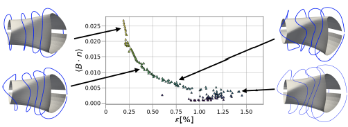
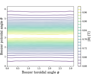
The coil set displayed in figure 5 reproduces the magnetic field sufficiently well, while not exceeding the strain limits on torsion and binormal curvature. Figure 6 shows the strain from torsion and binormal curvature along the coils. Figure 7 displays the contours of the magnetic field strength in Boozer coordinates for the equilibrium and the magnetic field created from the coils. The coils retain excellent quasisymmetry and introduce only small symmetry-breaking modes. Therefore, we find the smallest major radius compatible with quasisymmetry and use of ReBCO.
Optimised coil set (view from the top and the side) within strain limits for an EPOS candidate equilibrium. The coils are displayed in red. The yellow to blue colour scale indicates the field strength on the outermost closed flux surface in the magnetic field created by the coil set.
Torsional (orange) and binormal curvature (blue) strain for each of the coils shown in figure 5. None of the coils exceeds a strain limit of 0.2 % on 3 mm wide ReBCO tape (red dashed line).
Field strength contours in Boozer coordinates for an EPOS candidate configuration produced by the strain-optimised coils. We achieve remarkable quasiaxisymmetry using coils that confirm to the strain limits.
The coils presented above represent the current state of an ongoing optimisation effort. To improve the manufacturing and placement tolerances on the coil, we aim to combine the single-stage optimisation with a stochastic approach. The full optimisation cost function and the physics design of the EPOS stellarator will be detailed in an upcoming publication.
5. CSX: interlinked coils without full tape rotations
The Columbia non-neutral torus (CNT) was designed to investigate non-neutral plasmas confined to magnetic surfaces using planar coils (Pedersen et al. Reference Pedersen, Kremer, Lefrancois, Marksteiner, Pomphrey, Reiersen, Dahlgren and Sarasola2006). The magnetic configuration consists of two outer polodial field (PF) coils and two interlocking (IL) coils within the vacuum vessel. The Columbia stellarator experiment (CSX) will repurpose the PF coils and vacuum vessel of CNT to confine quasineutral plasmas with a quasiaxisymmetric magnetic field. The existing planar copper IL coils will be replaced by non-planar coils wound with non-insulated HTS tape on a three-dimensional printed bobbin. In constructing this experiment, we aim to validate the physics of quasiaxisymmetry, as well as demonstrate the compatibility of ReBCO tape for stellarators.
We present a preliminary IL coil design optimised for quasiaxisymmetry, $\iota \geqslant 0.15$
and plasma volume 0.1 m
$\iota \geqslant 0.15$
and plasma volume 0.1 m $^3$
(figures 8 and 9). Single-stage optimisation is performed using the Boozer surface approach, in which approximate magnetic surfaces of the vacuum field are computed in Boozer coordinates with a least-squares solver (Giuliani et al. Reference Giuliani, Wechsung, Cerfon, Landreman and Stadler2023). The plasma surface, IL curve and tape orientation DOFs are included in the optimisation. Coil constraints are imposed to ensure sufficient clearance between the IL coils and the vacuum vessel, and the coil length is constrained to be
$^3$
(figures 8 and 9). Single-stage optimisation is performed using the Boozer surface approach, in which approximate magnetic surfaces of the vacuum field are computed in Boozer coordinates with a least-squares solver (Giuliani et al. Reference Giuliani, Wechsung, Cerfon, Landreman and Stadler2023). The plasma surface, IL curve and tape orientation DOFs are included in the optimisation. Coil constraints are imposed to ensure sufficient clearance between the IL coils and the vacuum vessel, and the coil length is constrained to be $\leqslant 4.25$
m. Binormal curvature and torsional strain are penalised using (2.14) with thresholds 0.2 % and a tape width of 4 mm. To ease tape winding, we include the twist penalty function
$\leqslant 4.25$
m. Binormal curvature and torsional strain are penalised using (2.14) with thresholds 0.2 % and a tape width of 4 mm. To ease tape winding, we include the twist penalty function $J_{{twist}}$
to avoid any net tape frame rotations. To facilitate winding under tension, we also penalise the rotation angle between the centroid and Frenet frames of the tape using (2.15) evaluated for the Frenet frame. This reduces the concave features visualised at the top of the coil in figure 9. The single-stage optimisation result is shown in figure 8.
$J_{{twist}}$
to avoid any net tape frame rotations. To facilitate winding under tension, we also penalise the rotation angle between the centroid and Frenet frames of the tape using (2.15) evaluated for the Frenet frame. This reduces the concave features visualised at the top of the coil in figure 9. The single-stage optimisation result is shown in figure 8.
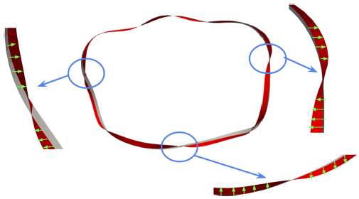
After the single-stage optimisation, the curve shape is fixed and the winding angle is again optimised for strain and frame rotation. The optimised tape path is shown in figure 9 (red), which does not deviate significantly from the centroid path (grey). The optimised strain values are below the chosen threshold, as seen in figure 10, showing that it is possible to obtain interlinked coils with sufficiently low strain and without full net turns of the winding pack. Achieving quasisymmetry with only two IL coils requires a certain amount of tape rotation and concave features. We aim to find excellent quasisymmetry with two IL coils while minimising such difficult to wind features. More details of the single-stage optimisation will be presented in a future publication.
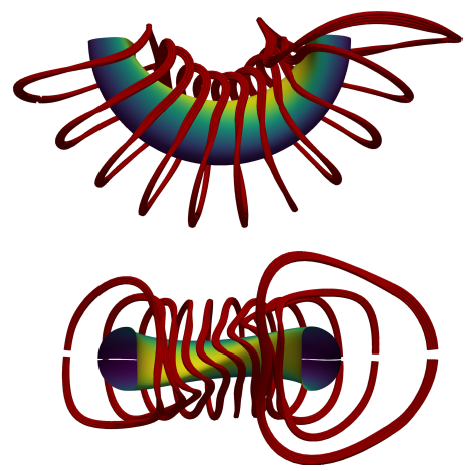
Preliminary CSX design consists of two planar PF coils outside the vessel and two non-planar interlinked coils inside the vessel, producing a quasiaxisymmetric equilibrium.

Tape orientation of the strain-optimised preliminary CSX coil is shown (red) in relation to the centroid frame (grey). The tape frame avoids any net rotations with respect to the centroid frame, as desired. The green arrows are meant to show the resulting winding angle optimisation.
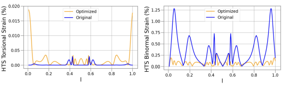
(a) Torsional and (b) binormal curvature HTS strain values are shown for the preliminary CSX coil. The curve obtained from single-stage optimisation is fixed and the winding path is optimised to obtain acceptable values of HTS strain.
6. Reactor winding pack
In this section, we demonstrate how strain optimisation allows to mitigate curvature- and torsion-induced strains for an HTS coil at reactor scale. Reactor-scale coils differ from experiments like EPOS or CSX as they require multiple stacks of tape to reach the desired current. In fact, a reactor requires coil currents in the range of 5–15 MA-turn, that would be impossible to realise out of a single stack, as DC power supplies rarely achieve currents above 50 kA. Such a coil requires 100–300 stacks, resulting in winding pack cross-section sizes of the order of 10 % of the coil average radius. Therefore, the values of curvature and torsion can change by more than 10 % across stacks, which requires not only the optimisation of the strain for a central filament, but for all stacks. Note that because stacks are wound in series, strain damage to any single portion of the HTS could make the entire coil fail.
For this study, we focus on the coils of the Wendelstein 7-X (W7-X) experiment, scaled at the reactor design point proposed for the HELIAS 5-B power plant, defined by the minor radius of 1.8 m and the average field on axis of 5.9 T (Schauer, Egorov & Bykov Reference Schauer, Egorov and Bykov2013). We also assume that HTS will cover 16 % of the cross-section of the winding pack and we consider a HTS tape stack of 12 mm x 12 mm, as 12 mm is the most popular HTS tape width from manufacturing companies. The winding pack cross-section side length $s$
is determined by a simple algorithm that accounts for the available space, assuming that two coils are almost touching at the point where the coil filaments get the closest to each other:
$s$
is determined by a simple algorithm that accounts for the available space, assuming that two coils are almost touching at the point where the coil filaments get the closest to each other:
 \begin{align} s = \frac {{\rm min}({ d}_{cc})}{\sqrt {2}} - t, \end{align}
where ${ d}_{cc}$
is the distance between two coils and the minimum is taken across all coils, and
${ d}_{cc}$
is the distance between two coils and the minimum is taken across all coils, and $t$
is the case thickness, here assumed to be 5 cm. The additional factor of
$t$
is the case thickness, here assumed to be 5 cm. The additional factor of $\sqrt {2}$
accounts for the diagonal of the square cross-section. This way, the coil orientation can be chosen arbitrarily, preventing any possible clash between adjacent coils when choosing the orientation to perform strain optimisation.
$\sqrt {2}$
accounts for the diagonal of the square cross-section. This way, the coil orientation can be chosen arbitrarily, preventing any possible clash between adjacent coils when choosing the orientation to perform strain optimisation.
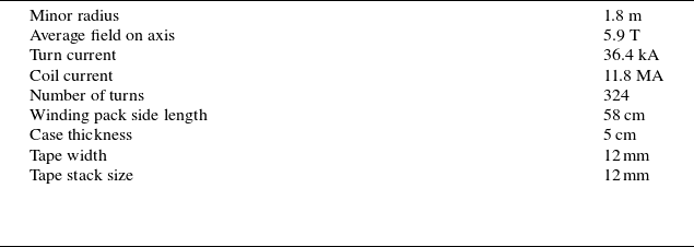
With these design criteria, we obtained coils with a cross-section of 58 cm x 58 cm, carrying a total current of 11.8 MA, 36.4 kA in each of the 324 stacks. The cross-section of the winding pack is schematically represented in figure 11(a). All the relevant information is summarised in table 1.
Reactor winding pack design parameters at the HELIAS 5-B design point (Schauer et al. Reference Schauer, Egorov and Bykov2013).
We assume that the relevant strains are the torsional and binormal, and we aim at reducing the sum of the two below 0.4 % at each stack in each coil.
The strain of each stack depends on its local orientation, which can be modified by changing either the orientation of the entire winding pack or the orientation of each stack individually. Allowing for a free orientation of each stack is a significant challenge from an engineering perspective. Another possibility is to modify the winding pack shape from a square cross-section with stacks arranged on a regular grid to a different shape. However, this option would require more engineering design and is therefore outside of the scope of this paper. Here, we limit ourselves to the optimisation of the winding pack orientation.
(a) Cross-section of a winding pack displaying the 324 ReBCO stacks. (b) Strain profile along the first coil, comparing the pure centroid orientation (blue) with the optimised one (orange). The solid line represents the median value, the shaded band illustrates the region between the 16 % and the 84 % quantiles, and the dashed line the maximum across each stack. The red dashed line shows the 0.4 % strain limit.
To avoid modifying the plasma equilibrium, we fix the centroid position, and we optimise for the orientation of the winding pack only. Figure 11(b) shows the strain profile along the first of the five independent coils in the coilset, for the pure centroid orientation (blue) and the optimised orientation (orange). The solid line shows the average strain, while the shaded region covers the region of one standard deviation around the mean value. The dashed line illustrates the maximum strain. In this case, the maximum exceeds the 0.4 % threshold in multiple regions. The optimised configuration lies safely below the limits at each point.
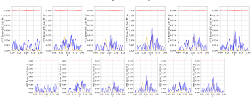
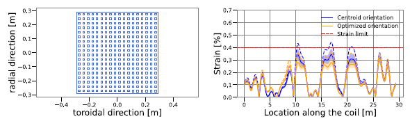
(a) Rotation angle as a function of the location of the coil, to be applied to the centroid frame to realise the strain-optimised orientation, for each coil in the coilset. (b) For each independent coil in the coilset (x-axis), the strain profile is summarised by the mean (solid circle), the standard deviation (error bar), and the maximum (diamond) for pure centroid orientation (blue) and the optimised one (orange). The red dashed line shows the 0.4 % strain limit. Following this approach, the maximum strain is decreased by more than 20 % in coil 2 which presents the highest strain before the optimisation.
The optimised rotation to be applied on the pure centroid frame is displayed in figure 12(a) across the coil, for the different coils. The effect of this rotation is visualised in figure 13, where the coils with a pure centroid orientation (blue) are compared with the optimised orientation (orange). The effect is subtle, as the regularisation introduced in (2.15) prevents large values of the angles. Further decreasing the strain in each stack may require a simultaneous optimisation of the strain and the central filament of the coil, which is beyond the scope of this study.
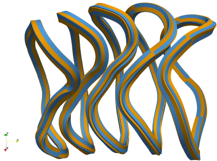
Winding packs (without casing) are displayed for the five independent coils with the pure centroid orientation (blue) and the optimised one (orange). While subtle, the difference is visible, especially when focusing on the third coil.
Last, we summarise the result of the optimisation in the plot in figure 12(b), where we compare the average (circle) and maximum (diamond) strain across all points and all stacks of each coil for the pure centroid (blue) and optimised (orange) orientation.
Thanks to the optimisation, all stacks of each coil are below the strain limits with a small, but carefully crafted rotation of the winding pack orientation.
7. Summary and outlook
Strain optimisation is crucial to ensure the integrity of stellarator coils made from ReBCO superconducting tapes. In this paper, we implemented a method to optimise the strain on ReBCO tapes in stellarator coils into the stellarator optimisation framework SIMSOPT. We penalise hard-way bending and torsion of the tape to lie within the mechanical limits of the superconductor. The winding plane for the tape is constructed from a frame of three mutually orthogonal vectors defined at each point. The local orientation of the frame and the curve of a filamentary coil are then optimised to minimise strain.
This method has been implemented into coil optimisation and applied to the design of the small stellarators EPOS and CSX as well as a scaled-up, reactor-relevant winding pack for the W7-X stellarator.
The EPOS and CSX projects implement the strain penalty into a single-stage optimisation. There is an additional term in the CSX cost function to avoid net rotation of the winding pack. The resulting coil sets retain good quasisymmetry at sufficiently low strain.
In § 6, the strain optimisation approach is applied to the W7-X coils scaled at reactor size, as defined by the HELIAS 5-B design point. First, we point out that the variation of curvature and torsion across turns in a reactor-scale winding pack is significant and needs to be accounted for. By exploiting the orientation of the winding pack as a degree of freedom, it is possible to reduce curvature- and torsion-induced strains below limits for every turn of an HTS non-planar coil at reactor scale, while keeping the overall coil shape and the individual orientations of each turn fixed.
Notably, curvature- and torsion-induced strains are not the only sources of HTS strains to consider for a reactor-scale coil. Other sources – such as the strain generated by the Lorentz load, the manufacturing process of the cable and the assembly of the coil – are outside the scope of this work and must be accounted for.
The strain optimisation described in this paper can be implemented into objective functions for coil optimisation together with other physics and engineering cost functions. Future work aims to condense other aspects of superconducting coil engineering, like $\mathbf j \times \mathbf B$
forces and the alignment between the ReBCO crystal axis and the magentic field on the coil into easy-to-compute penalties.
$\mathbf j \times \mathbf B$
forces and the alignment between the ReBCO crystal axis and the magentic field on the coil into easy-to-compute penalties.
Acknowledgements
P.H. thanks Jim-Felix Lobsien, Matt Landreman and Dario Panici for useful discussions. P.H. thanks Jens von der Linden for useful comments to the manuscript. The authors thank Carlos Paz-Soldan for providing his Matlab code.
Editor Per Helander thanks the referees for their advice in evaluating this article.
Funding
This work has been supported by the Helmholtz Association (VH-NG-1430), Simons Foundation Targeted MPS Program (Award 1151685), the PPPL LDRD program and the Simons Foundation MPS Collaboration Program (Award 560651).
Declaration of interest
The authors report no conflict of interest.


 Open access