


Introduction
Subglacial lakes are of considerable scientific interest as they potentially hold records of ice sheet and climate history, and contain unique life forms and ecosystems (Christner and others, Reference Christner2014) in one of the most extreme habitats on Earth. To date, over 400 lakes have been discovered across Antarctica (Siegert and others, Reference Siegert, Priscu, Alekhina, Wadham and Lyons2016) from shallow lakes at its margin (e.g. Tulaczyk and others, Reference Tulaczyk2014), to deep-water lakes within the ice-sheet interior (e.g. Woodward and others, Reference Woodward2010). These subglacial lakes exist where the geothermal heat flux is sufficient to melt the ice-sheet base, with heat flux estimates ranging from 55 to 285 mW m−2 in West Antarctica (Begeman and others, Reference Begeman, Tulaczyk and Fisher2017; Seroussi and others, Reference Seroussi, Ivins, Wiens and Bondzio2017).
Key goals of Antarctic subglacial lake research are to cleanly access and sample the lake water and sediments to understand these subglacial aquatic environments with minimal disturbance and contamination (Siegert and Kennicutt, Reference Siegert and Kennicutt2018). Samples would ideally provide answers to strategically important questions: can a subglacial lake isolated from the atmosphere or ocean for hundreds of thousands of years provide information about the development and diversification of life on Earth and elsewhere, and can lake sediments inform our knowledge of the presence or absence of the ice sheet during recent interglacial periods? (Kennicutt and others, Reference Kennicutt2015).
Accessing the base of deep ice sheets involves considerable technical and logistical challenges (Makinson and others, Reference Makinson2016). Critically, any access drilling activities must minimise all aspects of contamination and disturbance of the subglacial environment in compliance with the Scientific Committee on Antarctic Research (SCAR) code of conduct, which provides a guide to responsible scientific exploration and stewardship of these pristine systems (Siegert and Kennicutt, Reference Siegert and Kennicutt2018).
The first accessing of an Antarctic subglacial lake took place in February 2012 at Lake Vostok in central East Antarctica (Lukin and Vasiliev, Reference Lukin and Vasiliev2014; Lipenkov and others, Reference Lipenkov, Ekaykin, Polyakova and Raynaud2016). Refrozen lake water samples were later recovered using an ice core drill, although contamination from the hydrocarbon-based drilling fluids remains an issue (Alekhina and others, Reference Alekhina2018). For this reason, other lake access drilling has used hot water drills fitted with clean access technology (Rack and others, Reference Rack2014; Rack, Reference Rack2016).
To date, only two Antarctic subglacial lakes have been accessed and sampled cleanly. The first was Lake Whillans in early 2013, <2 m deep and overlain by 800 m of ice, as part of the Whillans Ice Stream Subglacial Access Research Drilling (WISSARD) project (Tulaczyk and others, Reference Tulaczyk2014). The second was at Lake Mercer in 2018/19 as part of the Subglacial Antarctic Lakes Scientific Access (SALSA) project where the ice thickness was 1092 m and lake depth of 15 m (Priscu and others, Reference Priscu2020; Siegfried and Fricker, Reference Siegfried and Fricker2018). Both of these subglacial lakes are beneath ice streams on the marginal plains of the Antarctic Ice Sheet (Siegfried and Fricker, Reference Siegfried and Fricker2018). Located within 100 km of the grounding line, where the ice goes afloat at the south-eastern edge of the Ross Ice Shelf, observations from Subglacial Lake Whillans show evidence of seawater input (Michaud and others, Reference Michaud2016) and flushing of the lake system (Smith and others, Reference Smith, Fricker, Joughin and Tulaczyk2009). Another project targeted the 150 m deep Subglacial Lake Ellsworth (SLE) (Siegert and others, Reference Siegert2012), located in a steep-sided subglacial trough within the Ellsworth Subglacial Highlands of central West Antarctica and overlain by 3150 m of ice (Vaughan and others, Reference Vaughan2007; Woodward and others, Reference Woodward2010). However, in December 2012 drilling was halted by a series of technical difficulties, raising multiple concerns about the viability of hot water drilling for accessing subglacial lakes beneath thick (>2 km) ice (Siegert and others, Reference Siegert, Makinson, Blake, Mowlem and Ross2014).
A series of smaller hot water drilling projects using the British Antarctic Survey (BAS) ice-shelf hot-water drill (Makinson and Anker, Reference Makinson and Anker2014), mainly on Filchner-Ronne Ice Shelf, were able to address many of the concerns and technical issues that arose from the SLE clean hot water drill (CHWD) (Siegert and others, Reference Siegert, Makinson, Blake, Mowlem and Ross2014). In early 2018, a new 2300 m hot water drill (Anker and others, Reference Anker, Makinson, Nicholls and Smith2021) underwent initial field-testing on Rutford Ice Stream for the BAS led Bed Access, Monitoring, and Ice Sheet History (BEAMISH) project. In early 2019, three subglacial access holes, up to 2154 m deep and up to 30 cm in diameter were successfully drilled to the ice-bed interface. The ice stream bed was unfrozen and had an existing, well-developed subglacial hydrological system. The bed itself comprised soft, water-saturated sediments, consistent with previous geophysical interpretations (Smith and others, Reference Smith2020). These three subglacial access holes are the deepest ever drilled using hot water techniques and they were maintained for up to 36 h. This clearly demonstrated the viability of deep hot water drilling for subglacial access and addressed many of the outstanding technical issues that arose from the unsuccessful drilling at SLE. This success paved the way for the exploration of suitable candidate subglacial lakes in central West Antarctica.
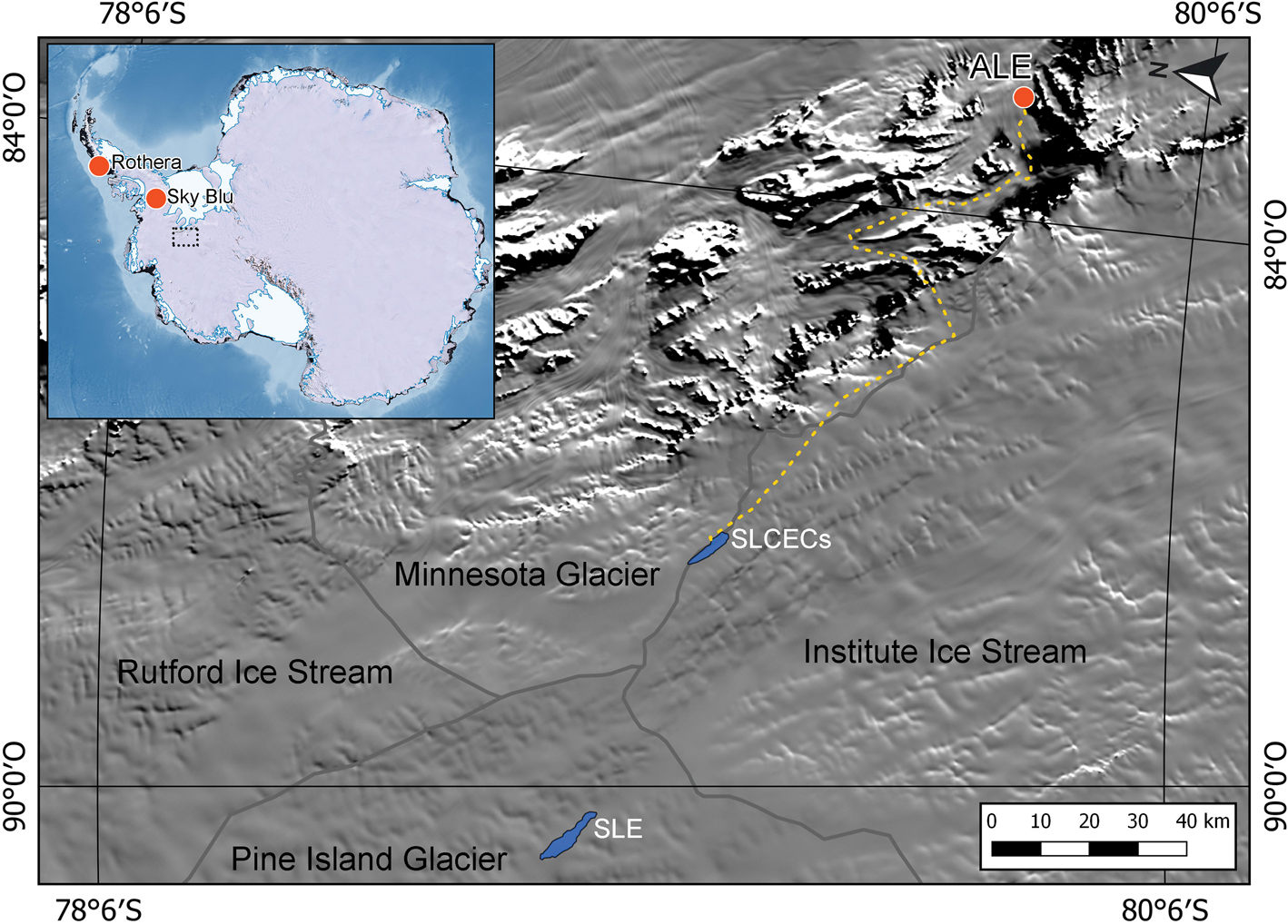
In January 2014, researchers from Centro de Estudios Científicos (CECs) discovered a subglacial lake, located in a deep subglacial fjord-like valley or trough at S79°14.5′ W087°35′. The lake is overlain with an average ice thickness of 2650 m (Rivera and others, Reference Rivera, Uribe, Zamora and Oberreuter2015), 500 m less ice than covers SLE. Subglacial Lake CECs (SLCECs) or formally ‘Lago Subglacial CECs’ (see Chile Gazetteer and the SCAR Composite Gazetteer of Antarctica) is ~65 km southeast of SLE and 20 km away from the western edge of the Ellsworth Mountains and lies on the ice divide between the Minnesota Glacier and Institute Ice Stream catchments (Fig. 1). Since its discovery, further radar and seismic surveys by CECs and BAS have mapped its extent (~2 km × 10 km) and determined its water depth (up to 310 m). The lakebed acoustic impedance also indicates the presence of soft silts and clays, but not sands. With comparatively thin ice cover, proximity to logistical hubs at Union Glacier and Sky Blu (Fig. 1), and confirmed lakebed sediments from three seismic survey lines, SLCECs became an ideal candidate for exploration.
A visible satellite image showing the region around Subglacial Lake CECs (SLCECs) and the overland traverse route (yellow dotted line) through the Ellsworth Mountains from Antarctic Logistics and Expeditions (ALE) hub at Union Glacier. Subglacial Lake Ellsworth (SLE) is also shown, and the grey lines indicate the different glacier catchment areas. The inset shows the BAS logistics support hubs of Rothera Station and Sky Blu.
Following the successes of deep drilling on Rutford Ice Stream, a joint UK-Chile collaborative partnership between the BAS (Cambridge, UK) and CECs (Valdivia, Chile) was started in 2019 for the exploration of SLCECs. The collaboration aims to deliver a clean access hole into the lake, and samples of lake water and lakebed sediment cores, to address key scientific questions.
Access to SLCECs will be achieved using a CHWD. By integrating components of the SLE CHWD (Siegert and others, Reference Siegert2012) into the successful BEAMISH hot water drill (Anker and others, Reference Anker, Makinson, Nicholls and Smith2021), supplemented with new equipment and systems, the new SLCECs CHWD is being developed to meet the SCAR cleanliness protocols (Siegert and Kennicutt, Reference Siegert and Kennicutt2018). This system also builds on decades of field experience and lessons learned from other hot water drilling campaigns and other clean access drilling (Priscu and others, Reference Priscu2013; Rack and others, Reference Rack2014; Siegert and others, Reference Siegert, Makinson, Blake, Mowlem and Ross2014; Rack, Reference Rack2016; Michaud and others, Reference Michaud2020).
The existing BEAMISH drill equipment will be traversed overland around the northern Ellsworth Mountains from the site on Rutford Ice Stream. Supplementary equipment being prepared in the UK will mostly be traversed from the logistic hubs at Union Glacier or Sky-Blu, with relatively small quantities flown directly to the SLCECs site.
Although consisting mostly of equipment already used in Antarctica, the SLCECs CHWD is nonetheless a new drilling system that will require testing and operator training. Initial UK testing will confirm that equipment to be integrated into the BEAMISH hot water drill system is fully operational and meet the necessary cleanliness standards prior to shipping. Once all project equipment is deployed to within a few kilometres of SLCECs, further testing will take place as part of a field season dedicated to integrating and commissioning all the systems that make up the SLCECs CHWD. This test site will be downwind of the planned lake access location to avoid contamination of the site. Planned testing includes driller training and full drill system operations with clean drilling to 500 m, together with practice deployments of the 15 cm diameter water samplers and 10 cm diameter sediment corer (Makinson and others, Reference Makinson2020). In parallel, biological sampling and field analyses, backed up by additional UK analyses, will be undertaken to test and validate field procedures and ensure adherence to the SCAR code of conduct for subglacial access prior to the SLCECs access drilling.
Drill system overview
The high-level SLCECs CHWD system requirements are to:
• operate reliably at 2000 m altitude with temperatures down to − 35°C,
• survive winter storage temperatures of − 55°C,
• operate through ice with minimum mean annual temperatures of − 32°C,
• provide a clean access hole, ~30 cm in diameter to 2650 m depth
• support the clean deployment and recovery of various probes and samplers,
• minimise drill time and fuel consumption,
• remain compatible with the available logistics, and
• maintain safe and predictable field operations.
Following the completion of the BEAMISH drilling on Rutford Ice Stream, the drill and supporting equipment was winterised for safe storage and remained on site. By reusing this now proven drill system as the foundation for the new SLCECs CHWD, the technical risks, financial costs and logistical burden are greatly reduced. Nevertheless, upgrades are necessary to meet the CHWD specification (Table 1) and cleanly access SLCECs by incorporating the following major enhancements, including reusing equipment from the SLE project:
• Dual drill water filtration systems and UV units
• High-temperature and high-pressure drill water pumps
• Additional water storage
• Hose cleaning and sterilising LED UV lamps
• Tents for drill plant and wellhead operations
• New diesel generators for 2000 m elevation
• Additional water heating units for 2000 m elevation
• Replacement 32 mm bore drill hose (2800 m continuous)
• Closed water heating circuit and primary plate heat exchangers
SLCECs CHWD specification

Fuel requirements
Fuel is a key element for any hot water drilling activity and significant volumes are needed on site.
New hot water drill systems can experience early difficulties resulting in far higher initial fuel usage than planned (see Fig. 6 in Benson and others, Reference Benson2014) and a major equipment failure can also result in the loss of the hole. Having a high level of contingency to accommodate unforeseen breakdowns and stoppages is therefore essential. To drill a >30 cm diameter hole to access SLCECs, 14 m3 of Avtur has been allocated, with at least an additional 5 m3 allocated if a further ream of the hole is needed. Further fuel is required to support the camp infrastructure, initial drill placement and drill test season. The available on-site contingency for all these activities is >100% to accommodate major delays or equipment failures.
Planned drill site layout
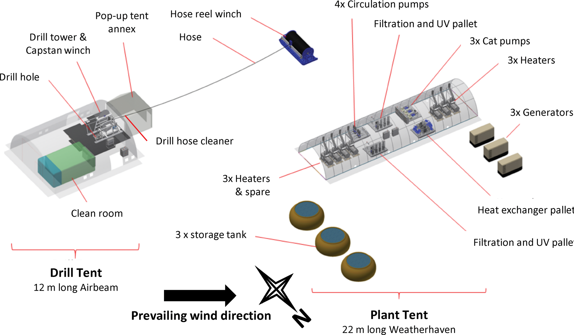
The SLCECs CHWD site layout will be adapted from the recent BEAMISH project where the vulnerability of the drill equipment and the weeklong 24 h drilling operations to poor weather and several storms was highlighted (Smith and others, Reference Smith2020). In addition, the SLCECs site is at a higher altitude of 2000 m where summer mean daily temperatures rarely rise above −20°C, and can be as low as −35°C. To mitigate against weather-related risks, large tents will house most of the CHWD and lake sampling equipment. For the unhoused drill hose reel, an insulated cover together with its large thermal mass will prevent freezing for 1–2 h in the event of a pumping system failure.
A Weatherhaven S4 framed arch tent (W6.1 m × L21.9 m × H3.6 m) will house most of the drill plant, including boilers, heat exchangers, low and high-pressure pumps, filtration and UV units (Fig. 2). The tent has multiple cabling ports, exhaust roof vents and access doors up to 3.66 m wide. The second tent (W10 m × L12 m × H4.65 m) will house the wellhead operations that include the drill capstan, tower, drill controls, submersible pumps and equipment for clean sampling of the lake and its sediments within a clean tent (Fig. 2). To avoid the need for working at height during erection of the tent, the Weatherhaven air beam tent uses air compressors to inflate the 15 cm diameter arch beams and 7.6 cm longitudinal beams to a working pressure of 600–800 kPa, allowing full deployment by four people in under 3 h. The air beam tent has multiple cabling ports, with side and end wall access doors up to 4.5 m wide and 3.8 m high. Both tents can withstand temperatures of −45°C, wind speeds of 22 m s−1 and snow loading of 25 kg m−2. In addition, an annex pop-up tent will be used during the drilling and sampling operations to house the drill capstan and tower.
Schematic of the proposed SLCECs drill site layout accounting for the prevailing south-easterly wind direction during summer months. For detailed site weather station data, see Figure 3.
December–January wind rose from multi-year SLCECs automatic weather station data.

The orientation of the site is important in maintaining the cleanliness of the areas around the wellhead drill tent and the surface snow used to make the seed water for initiating the hot water drilling process. Several years of automatic weather station data from the site show that winds during summer (December–January) are almost exclusively from the south and east, with no wind events from the northwest (Fig. 3). Therefore, the wellhead drill tent will be upwind in the south-east sector, away from heater, generator and vehicle exhausts, and all other general camp activity.
SLCECs clean hot water drill architecture
The SLCECs CHWD is an integration of BEAMISH and SLE drill components that are proven to work well in a field environment. The fundamental change from the BEAMISH drill is the need to provide a clean hot water system, hence the SLE thermal architecture is adopted for the SLCECs drill.
The SLCECs thermal system is divided into two parts, a primary heating loop and a drill water loop that must remain clean. Heat is transferred between the loops via stainless steel plate heat exchangers. Separating the complex multi-unit heat production plant reduces the risks of drill water contamination, simplifies the drill water loop and allows almost the entire drill system to operate at about one-tenth pressure of the BEAMISH system, enhancing operational safety.
The primary water-heating loop is a closed system divided into two halves (Fig. 4). Paired pumps take warm 15–20°C water from the storage tank and supply three main heaters. The hot 90–95°C water then enters pairs of plate heat exchangers and exits at 15–20°C, returning to the water storage tank. A failure of either a paired pump or heat exchanger will not affect the performance of the drill. Each half of the system also has a single pump supplying water for the exhaust heat recovery loop.
Schematic diagram of the SLCECs CHWD equipment, water circulation systems and sensors.
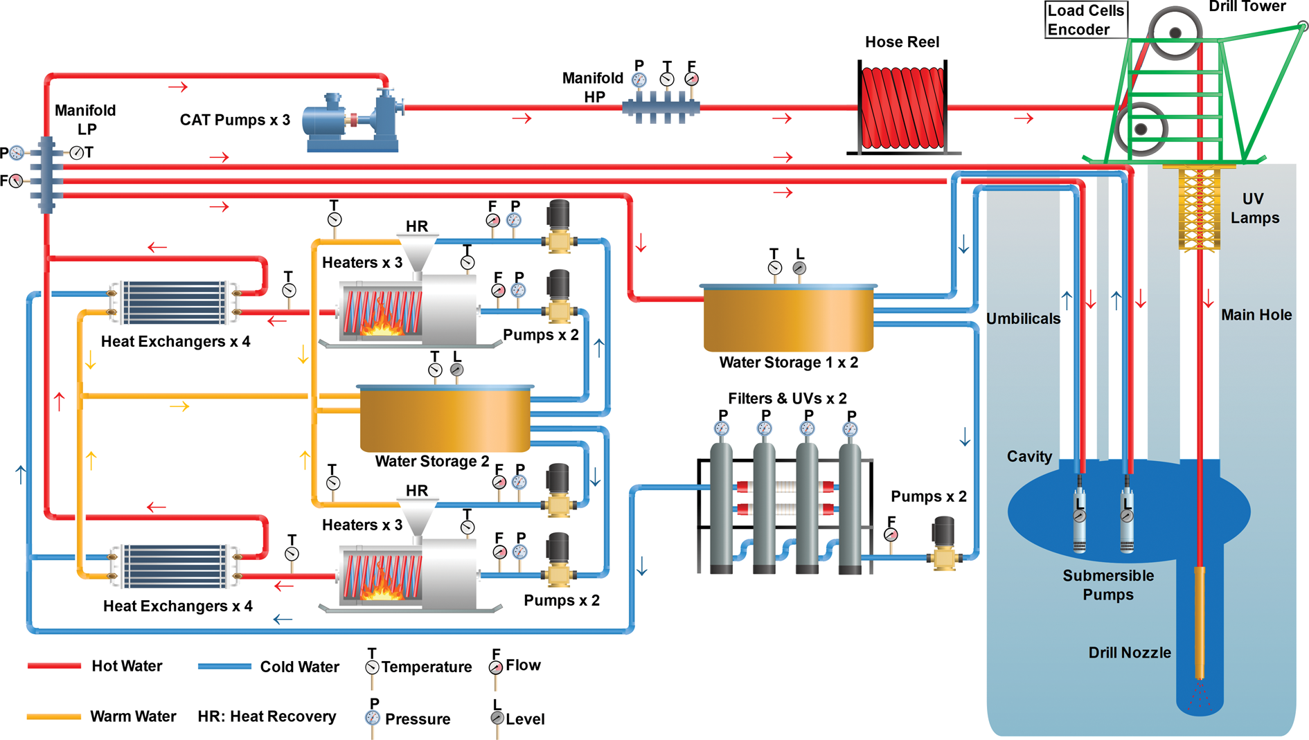
The drill water loop uses water stored in two surface storage tanks (Fig. 4). Pairs of pumps supply water to a series of four filters and two sterilising UV units. A failure of one of these pumps will not affect the performance of the drill. A duplicate system of pumps, filters and UV units allows filter changes and repairs without disrupting the drilling process. The filtered and sterilised water passes through the pairs of stainless-steel heat exchangers and is heated to 90°C. At the low-pressure manifold, some clean hot water is diverted to pre-heat the drill water storage tanks, while some is used to warm the umbilicals, submersible pumps and cavity to minimise the risks of freezing. Most of the clean hot water is fed to the high-pressure CAT pumps that supply the drill nozzle, via the 2.8 km drill hose, to drill the lake access hole. The drill water flows up the access hole to the cavity, from where it is pumped back to the surface water storage tanks for re-use by the drill system. Almost all components in this drill water loop are stainless steel.
Drill equipment
Generators and power distribution
The primary electrical power is provided by Kohler SDMO R110 three-phase generators with a nominal maximum continuous output of 100 kVA, de-rated to 80 kVA at 2000 m altitude and running on Avtur (JET A-1). These generators output 415 V at 50 Hz, supplying three-phase power for pumps, winches and other drill equipment. The four-stroke, tier three, John Deere turbo engines, modified with lubricity filters for Jet A-1, were selected as they are almost identical to other units operating in Antarctica and are compatible with existing long-term generator operations and expertise within BAS. The modified generator housings, which include the generator controls, allow them to operate in high winds with blowing snow and ensure safe overwintering at field sites.
The power distribution across the site uses Titan power ‘cubes’, providing multiple single- and three-phase sockets at 16, 32, 65 and 125 A, as well as including essential circuit breakers and safety systems. Several smaller site generators, running on petrol, provide power for smaller system testing and auxiliary camp power.
Melt tank and small storage tank
The initial seed water for the CHWD is generated from the clean sector surface snow that is hand shovelled into a small 50 L melt tank with heat supplied either electrically (5 kW) or using an Avtur oil burner (60 kW). The water is pumped into a 300 L tank, providing sufficient water to prime pumps and main water heaters, accelerating the snow melting process. Once the full heating system is operational, clean snow is pushed to the water storage tanks by PistenBully and immediately hand shovelled into the main water storage tanks to be melted.
Water storage tanks
The flexible and robust food grade PVC-coated polyester fabric tanks each provide 30 000 L of covered surface storage capacity. At least 50 mm of closed-cell ethafoam insulation beneath the tanks prevents melting and sinking into the snow surface as the stored water is maintained at >10°C. Two tanks hold the clean drill water, and one holds the recirculating main heating plant water. Two smaller 10 000 L tanks are also available.
Low-pressure pumps
To circulate water within the system, Grundfos multistage pumps (CR 15-5 A-F-A-E-HQQE) with stainless steel wetted parts are used (Fig. 5). These 4 kW, five-stage centrifugal pumps have a maximum operating pressure of 700 kPa. The typical set point of each pump should be 110 L m−1 at 670 kPa. All have variable frequency drive (VFD) motor controllers. These pumps take the water from a surface tank and provide enough pressure and flow for the heat exchangers and boilers to operate efficiently. Similarly, identical pumps are used in the filter and UV system. Each pump has a working spare to ensure full redundancy.
Model of lower pressure pumps pallet.

Main heating plant
Six Exchange Engineering heaters (Fig. 6), each with a nominal output of up to 250 kW, de-rated to 200 kW for altitude, will provide the 1.2 MW of required heating capacity. Each unit consists of 100 m of 19 mm bore stainless-steel tube wound into a double coil rated to 7 MPa. The oil burners are Nu-Way MOL 350 units, operating on 230 V and at a fuel pressure of 860 kPa, each consuming ~0.44 L min−1 of Jet-A1 at sea-level. Each unit is fitted with adjustable high-temperature and low-flow cut-off switches and alarms. The maximum operating water pressure is 700 kPa from the low-pressure centrifugal pumps. Each heater has a chimney fitted with a simple exhaust heat recovery unit (Fig. 6) consisting of finned heat exchangers that reduce the air temperature from ~400°C to <200°C, recovering 10–15 kW from each unit. Two 0.9 kW centrifugal pumps circulate water through the heat recovery units from the heating loop water storage tank.
Model of a single water heater with exhaust heat recovery system and chimney.

Plate heat exchangers
The plate heat exchangers are constructed from multiple copper brazed 316 stainless steel plates, transfer thermal energy from the heating loop, to the clean drill water loop (Fig. 4). The four pairs of heat exchangers, with each pair in series (Fig. 7), provide the required energy transfer capacity together with full redundancy, as the hoses and valves allow each half to be isolated. Each pair takes hot water from the heaters at 95°C and returns it at >20°C at a flow rate of 121 L min−1 in the heating loop. In the clean drill water loop, the 109 L min−1 flow is heated from ~10°C, up to 90°C, a heat transfer of 613 kW. The pressure drop through a pair of heat exchangers is 47 and 41 kPa for the heating and drill water sides, respectively. Pressure relief valves are fitted to each heat exchanger pair. Most of the piping, valves and connections are provided by 1.5″ stainless steel sanitary tri-clamp fittings with a maximum designed pressure of 1 MPa Low pressure (1.5″ food grade ExtremeFlex®) hose is used to distribute the clean drill water and recombine it after heating.
Model of plate heat exchanger pallet showing the four heat exchanger pairs.

Filtration and UV
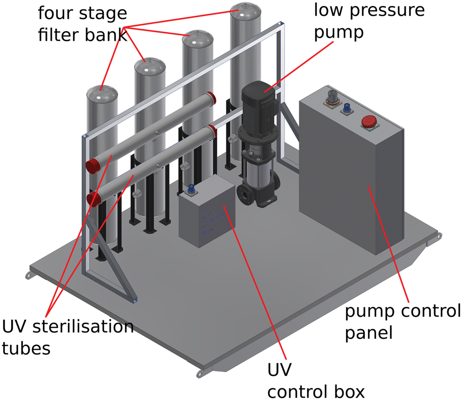
Designed to remove suspended particles, including dust, bacteria and large viruses, the four-stage filtration consists of 20, 5, 1, 0.1 μm absolute filters. A UV unit (ATG UVL-200-4) with 254 nm high-intensity 200 W biocidal UV lamps delivers a dosage of >40 mJ cm−2 and log-4 cell reduction. The filtration and UV units have been refurbished from the SLE CHWD (Siegert and others, Reference Siegert2012). An additional 80 W UV unit (EUV-80W-G2) with a 185 nm ozone-generating UV lamp delivers a dosage of 45 mJ cm−2, a log-4 cell reduction and oxidises dissolved organic carbon. One-half of the system is shown in Figure 8. Between each stage of the filtration and UV system and elsewhere along the clean drill water circuit, ports will allow a time series of water samples to be collected and analysed, to ensure drill water cleanliness as it passes through each stage of the CHWD. Differential pressure sensors across each filter monitor the level of clogging occurring, which will increase with use. If filters clog or a UV unit fails, drill water treatment can be switched to the spare filtration and UV system without any interruption to the drilling process. System testing in the UK will check that it meets the specification for the removal of particles and bacteria and provides the required levels of disinfection of the water. A time series of water samples, from multiple sample points, will be collected and laboratory analysed to assess system performance. During full operational field testing near the SLCECs site, the same sampling and testing will be carried out.
One-half of the filtration and UV system, pallet mounted.
High-pressure pumps
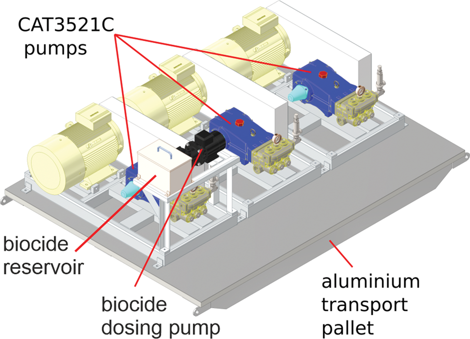
Reconfigured from the SLE CHWD, the refurbished high-pressure triplex CAT3521C pumps with 22 kW motors (Fig. 9) are each controlled with Lenze VFD's. Each pump unit can operate with water at 90°C with special PTFE high-temperature seals and deliver 80 L min−1 and includes pressure pulsation damper, relief valve, regulator valve and pressure gauge. A low-pressure flush pump manifold with ports between the high- and low-pressure plunger seals fitted to the CAT pumps is used with a biocide flushing liquid as a precautionary measure to prevent any biological contamination of the drill water. The flushing liquid is cooled by simple radiative heat loss and allows the pump to operate with increased reliability at an elevated temperature. To prevent cavitation and damage to the pump, the 90°C drill water is supplied to the intake at ≥350 kPa. The three pump units will deliver up to 160 L min−1 of drill water at between 7000 and 9000 kPa. If necessary, two units can provide the required flow rate, allowing offline repairs or servicing without affecting the drilling operation.
High-pressure CAT pumps with biocide flush pump, pallet mounted.
Drill winch system, hose and nozzle
The drill tower and sheave, capstan, and hose reel (Fig. 2) with a Uhing® rolling ring level wind are the units as used for the BEAMISH project (Anker and others, Reference Anker, Makinson, Nicholls and Smith2021) and are able to accommodate the replacement 2800 m drill hose. The VFD controlled hose reel in torque mode maintains tension in the hose to prevent any slippage on the capstan and winds the hose back onto the hose reel. The VFD-controlled capstan drive (Fig. 10) powers the drill hose up and down the access hole and has a highly controllable speed range of 0.1–9.1 m min−1. The sheave wheel (Fig. 10), with an axel height of 3 m, is instrumented with a shaft-mounted encoder for drill speed and depth, and dual load cells for the down hole load or tension on the drill hose.
(a) Wellhead layout schematic and cutaway showing winch tower, capstan drive and crescent sheaves for submersible pump borehole umbilicals. (b) Photo of a BEAMISH umbilical over the crescent rollers.

As the ice thickness at SLCECs is ~2650 m, an identical 2800 m single length drill hose will replace the hose used at BEAMISH. The hose has a 1.25″ bore PA11 nylon core with a Kevlar® over braid and extruded Hytrel®6356 outer sheath, which is flexible and tough, ideal for winching applications. This material is also resistant to both the high-pressure water jets used in the drill hose cleaner and the high-dose UV in the wellhead collar (Fig. 10). The maximum working pressure is 14 MPa and tensile tests to 920 kg show the hose stretch is ~0.9% per 100 kg loading. To achieve the specified flow rates through the longer drill hose, pumping pressures may increase above 7 MPa, therefore the rotary water coupling on the hose reel was uprated to 14 MPa.
The drill nozzle will be of similar construction to that used at BEAMISH (Anker and others, Reference Anker, Makinson, Nicholls and Smith2021) but will be modified to allow effective cleaning with either 70% ethanol or 3% hydrogen peroxide during its field assembly and deployment. The water jet configuration will remain the same and the total weight of ~150 kg is sufficient to easily overcome the combined effects of thrust from the water jets, the buoyancy of the hot water in the drill hose and any friction from the borehole sidewalls.
External hose cleaning and sterilisation
It is essential that equipment entering the lake access hole attain the required high-level of cleanliness, including the exterior of the drill hose. The first stage of cleaning is to remove any remaining particles on the drill hose surface using a series of high-pressure jets of sterile hot water that has been filtered and UV exposed. A co-located annular air knife, with air supplied from a medical grade compressor, will remove water droplets. The drill hose cleaning unit is located in front of the capstan guide rollers (Fig. 10) during drilling operations. The new drill hose will first be cleaned as it is wound from its storage reel onto the winch hose reel during the test season and then during test drilling to 500 m. Prior to and during drilling the capstan guide rollers, capstan and sheave wheel grooves will be periodically cleaned with 70% ethanol or 3% hydrogen peroxide.
On entering the top of the borehole, the UV-resistant hose is exposed to sterilising 275 nm UV. A 275 nm UV LED wellhead unit is being developed to provide a dose >40 mJ cm−2 to all equipment lowered into the borehole (Fig. 11). This dose should achieve at least a 2-log (99%) inactivation of most spore-forming bacteria (Priscu and others, Reference Priscu2013) and a 4-log (99.99%) inactivation of most commonly found microorganisms (bacteria, viruses and protozoa). This unit is being adapted from an existing UV LED water disinfection system by Typhon Treatment Systems Ltd. (Autin and Bolton, Reference Autin and Bolton2019; Jarvis and others, Reference Jarvis, Autin, Goslan and Hassard2019). The wellhead consists of a 30 cm ID quartz tube, around which rings of high-intensity UV LEDs are positioned (Fig. 11). Each ring consists of 20 LEDs, with individual LED drivers, and the number of rings can be increased if a higher dose is required. Modelling has shown that when drilling with a 44 mm OD hose descending at 1 m min−1, only one ring of 20 LEDs is required. To verify the effectiveness of both the drill hose cleaner and the UV LED unit, UK and then field tests will be undertaken. Swabs taken from the drill hose surface will be used to assess the effectiveness of the high-temperature, high-pressure hose cleaner in removing particles from its surface and of the UV LED unit to sterilise the hose surface.
(a) An outline drawing of the proposed UV LED borehole wellhead unit and (b) an image though an off-the-shelf Typhon UV LED wellhead reactor with 20 UV LEDs per ring.

Unlike mercury lamps, UV LEDs produce instant UV power as soon as they are switched on and are not adversely affected by cold temperatures, making them ideal for wellhead operations. The LEDs have a 20 000 h minimum life and are much more robust than traditional mercury bulbs.
To ensure personnel safety while working around the borehole UV system, ray paths will be enclosed within the wellhead and an iris will close around the hose to prevent any residual UV light leaking out. The iris will have an integrated interlock switch to turn off the LEDs when the iris is open, or when the hose is stationary for any significant amount of time to avoid damage to the drill hose from prolonged UV exposure.
Submersible borehole pump and umbilical
The two submersible pumps and umbilicals recover drill water to the surface storage tanks for re-use by the drill (Figs 2 and 4). This system will use the same equipment and procedures as established at BEAMISH (Anker and others, Reference Anker, Makinson, Nicholls and Smith2021). The pump is a Caprari E6XDB25/40 multistage centrifugal submersible pump, with a 9.2 kW, three-phase motor, with VFD control. Operating at 50 Hz, each pump can deliver 120 L min–1 from 280 m depth, ~30 m below the estimated hydrostatic water level after breakthrough. A spray block manifold, connecting the pump to the umbilical hoses, jets hot water laterally to form, enlarge and then maintain the borehole cavity at above 0°C.
The umbilical consists of an H07RN-F three-phase power cable, 1.25″ bore thermoplastic return hose, and a 0.75″ thermoplastic hose to deliver hot water to the pump and cavity. Plaiting the hoses and power cable has proven to be a reliable, field repairable and cost-effective solution, for making umbilicals (Anker and others, Reference Anker, Makinson, Nicholls and Smith2021). A double-shielded twisted pair cable and water-level sensor are also attached to each umbilical to provide the primary indication of when the borehole water level rises as the drill reaches the lake.
Having dual submersible pumps improves system reliability, as in the event of a failure, sufficient water can still be recovered to the surface storage tanks, allowing drilling to continue uninterrupted for several hours while repairs or replacement are undertaken on the failed system. A jib and roller, integrated into the drill tower (Fig. 10), are used with a small truck winch to initially lift the pump into the hole. A PistenBully vehicle is used to safely and accurately lower or raise the 1000 kg umbilical and pump assembly within the borehole over the roller crescent sheaves (Fig. 10b).
Monitoring system
The monitoring system will display and log the main drill parameters of the SLCECs CHWD, in a similar way to the BEAMISH system (Anker and others, Reference Anker, Makinson, Nicholls and Smith2021). However, this design will have additional sensors to comprehensively monitor the drill. Primary drill parameters are taken from the instrumented drill tower sheave wheel (load cells and encoder) and from the instrumented high- and low-pressure manifolds (temperature, pressure and flow) (Fig. 4). Additionally, pressure sensors will monitor the water level of the cavity, next to the two submersible borehole pumps. Other sensors including temperature and water-level sensors in the water tanks; differential pressure and water flow sensors for the two filtration units; and several temperature, pressure and water flow sensors for the heating, drill water and heat recovery loops will monitor the drill sub-systems (Fig. 4).
Most of the sensors have 4–20 mA current analogue outputs, which are converted to digital signals using Red Lion CUB5 units. Each unit displays the sensor value and has an RS485 serial interface to communicate with the rest of the system. Several units will be grouped together, and located on each pallet, close to the sensors. A group of CUB5 units will share a common RS485 bus and converted to Ethernet or Wi-Fi using Moxa NPort W2150A devices. Thus, all data measured by the various sensors will be transmitted through this general TCP/IP network into a central server, implemented by a fanless InCar CQ53P computer (Fig. 12). This platform will run several services: (1) a custom software will collect all data generated by CUB5 units, put them into CSV files and into the database, (2) Graphite, a database specially designed for numeric time-series data storage and display, (3) Grafana, a web-based interactive visualisation application for time-series data and (4) other minor services such as GPS time synchronisation, data backup and network status. Field personnel will be able to access the sensor data in real-time, and see historical data of each sensor, using a web browser and connecting to the Grafana web interface.
Schematic of the drill monitoring system.

Borehole measurement system
A borehole measurements system has been developed and is described in detail in another paper in this volume (McAfee and others, Reference McAfee2021). This standalone logging unit is a multi-sensor programmable borehole measurement system assembled within a 2.8 m long and 16.5 cm diameter frame. This unit will be attached directly to the drill hose, >10 m above the drill nozzle, and allows measurements to be gathered during drilling. Data from the system are not transmitted to the surface but are logged locally. When the logger is returned to the surface, the data can be accessed. The sensors integrated into the measurement system include:
• Two single-axis inclinometers
• One three-axis magnetometer
• Two Attitude and Heading Reference Systems (AHRS)
• Three ultrasonic rangefinders which are used to measure the borehole diameter
• Pressure and temperature
• One downward or upward looking camera
• Two sideways looking cameras
The combination of visual and other sensor data is used to assess hole straightness and verticality and confirm cavity connections between holes during the initial stages of drilling. On completion of drilling, the diameter measurement data will confirm if the hole is large enough to allow lake sampling operations commence and prevent entrapment of samplers and loss of the hole as it refreezes.
Drilling method
All hot water drills at sites with porous snow and firn require water recovery from the borehole for reuse by the drill. Also, to prevent the loss of borehole water into the hydrological system and allow further hole enlargement after achieving subglacial access, water recovery pumps must also be located below the local hydrological level. At SLCECs, the firn depth is estimated to be 67–77 m based on firn data from the West Antarctic Ice Sheet Divide ice core (Battle and others, Reference Battle2011) and the local hydrological level is likely to be ~250 m (Rivera and others, Reference Rivera, Uribe, Zamora and Oberreuter2015). However, if there are significant variations in the local firn depth and ice density, the hydrological level could be as low as 280 m. To establish the water recirculation system and prevent entanglement between the pump umbilicals and drill hose, separate parallel holes that are straight and vertical, and interconnected at depth are required over the upper part of the hole. Some of the greatest complexities and risks during the drilling process are associated with establishing this water recirculation system below the firn level. Here we present two approaches to dealing with this challenge, one using only the CHWD and the other using a new large diameter wireline augur drill.
During the BEAMISH project, it was clearly demonstrated that straight and vertical holes, interconnected at depth, could be hot water drilled to establish a water recirculation system at 235 m depth. The same method described by Anker and others (Reference Anker, Makinson, Nicholls and Smith2021) and shown in Figure 13a can be used during field testing season, and accessing of SLCECs. Two borehole pumps and their umbilicals provide system redundancy and reliability. Establishing a shallow recirculation system minimises the loss of drill water into the porous firn. Further drilling then enables the formation of a deep cavity ~40 m below the hydraulic level, at an estimated depth ~250 m (Rivera and others, Reference Rivera, Uribe, Zamora and Oberreuter2015). Water-level sensors and camera inspection will confirm the interconnection of the <1 m spaced holes at the deep cavity. The water-level pressure sensors are also critical to informing the drillers of the precise moment when breakthrough into the lake occurs. Once the lake is accessed, the pumps and umbilicals are repositioned <5 m below the water surface to mitigate against them freezing in the water-filled section of the hole. The formation of a new cavity (Fig. 13) then prevents ice formation on the borehole water surface during the 10–20 h of lake sampling operations.
Schematic of two different drilling methods for establishing holes with 0.8–1.0 m separation and interconnecting cavities (black) for the water recirculation system at least 10 m below the deepest predicted hydraulic level of SLCECs. The red lines indicate the positioning of the submersible borehole pumps and umbilicals. (a) Using the CHWD, a shallow cavity and recirculation system is established (1a–1b). A deep interconnecting cavity is then formed below the predicted hydraulic level (2–3). The water level is drawn down to the deep cavity by the borehole pumps and drilling continues to the lake (4), and on accessing the lake, the depth of the pumps and cavity are adjusted to the hydraulic level (5). (b) Using BigRAID, three holes are drilled to below the predicted hydraulic level (1). The deep interconnecting cavity is formed using the CHWD borehole pumps and lateral sprays (2–3), with drilling progressing to the lake (4), and then adjusting the pumps and cavity depth (5) after accessing the lake.

A new alternative drilling solution for providing straight and vertical holes through the porous firn and to a depth below the hydrological level is undergoing cold testing in preparation for use at Summit Station, Greenland during 2021. Based on the BAS Rapid Access Isotope Drill (RAID) (Rix and others, Reference Rix, Mulvaney, Hong and Ashurst2019), the new 26 cm diameter semi-automatic wireline auger, BigRAID (Fig. 14), will have the capability of drilling a dry hole to 300 m in 4 days, using ~270 L of fuel. BigRAID is an electromechanical drill with full-face cutters. Chippings are collected and transported into the chippings barrel using a spiral (Fig. 14). Once full, the drill is withdrawn to the surface, and the chippings ejected by reversing the motor. The key benefits are regular-shaped holes through the firn and a reduction in hot water drilling time and operational complexity (Fig. 13). Also, with no water lost into the firn, the risk of the umbilicals becoming frozen against the hole sides because of water leaking from the firn is removed. By using BigRAID, ~2500 L of fuel is saved per site, easily offsetting the logistics burden of the extra 350 kg for the drill, cable and spares. Furthermore, the wellhead system and holes up to 300 m deep can be established in parallel with the CHWD setup.
Diagram showing the 26 cm diameter BigRAID and cross-section A-A showing the internal components.

Once the three straight and vertical holes are complete, a UV source (e.g. Keen and Brito, Reference Keen and Brito2014) could be lowered into the holes if the BigRAID drilling process is proven to be insufficiently clean during the test field season. A 30 W, 254 nm source, lowered at 1 m s−1 would provide the required >16 mJ cm−2 as per ANSI/NSF Standard 55–1991, for a >log-4 cell reduction (Siegert and others, Reference Siegert2012) in the 26 cm diameter boreholes. Alternatively, the hot water drill could enlarge these holes by a few centimetres to expose a new firn and ice surface. Either option would ensure the air-filled section of the boreholes were clean. The process of interlinking them with a cavity melted out by the CHWD can begin as shown in Figure 13b. Once the cavity interlinks all three holes, each separated by 0.8–1.0 m, the remaining pump and umbilical are deployed, and drilling of the lake access hole can begin.
From the interlinking cavity, the drilling target diameter for the SLCECs access hole is >30 cm to guarantee a >25 cm hole when lake sampling deployments begin. This minimum diameter is needed to safely accommodate and recover the 15 cm diameter water samplers and the following 10 cm diameter sediment corer (Makinson and others, Reference Makinson2020). Drilling speeds will range from 1.7 m min−1 near the surface to 0.7 m min−1 in the lower 1000 m of the hole as the drill water cools from 90°C at the surface to <40°C at the base of the hole. To allow for heat loss into the ice and refreezing, the initial hole diameter near the drill nozzle will be up to 40 cm. After reaching the lake, the returning drill reams the hole at 6 m min−1, with the drilling and return ream expected to take almost 2 days. Once the hole is complete and sampling is underway, maximum refreezing rates in the coldest ice will not exceed 0.5 cm h−1 in diameter. Towards the base of the hole, refreezing rates decrease and reach zero at the ice base as the ice warms to the in situ melting point. Drilling prediction software from BEAMISH (Anker and others, Reference Anker, Makinson, Nicholls and Smith2021) and a modified version of the IceCube software (Greenler and others, Reference Greenler2014) will be used to model the hole size, its time evolution and to maximise the usability of the hole during lake sampling. During drilling operations, surface data from the drill system will be used to update and refine the rate of drilling. On recovery to the surface, supplemental data from the borehole measurement system McAfee and others (Reference McAfee2020) that includes diameter measurements will be used to verify the hole size predictions.
Prior to accessing the lake, the water level will be lowered significantly below the 250 m level (Rivera and others, Reference Rivera, Uribe, Zamora and Oberreuter2015) and >10 m below the lowest possible hydrostatic level of ~280 m to prevent borehole water entering the lake. On reaching the lake, a further consideration is the risk posed by dissolved gases and clathrates in the lake water as it enters the borehole. Comprehensive assessments of the similar nearby SLE (Clarke and Consortium, Reference Clarke2012; Brito and others, Reference Brito, Griffiths, Mowlem and Makinson2013) consider the overall risk of a sudden release of high-pressure gas from the lake, or blowout, to be very low. Also, during the accessing of Lake Vostok, lake water rose almost 600 m up the borehole without any release of gases occurring (Lukin and Vasiliev, Reference Lukin and Vasiliev2014). Therefore, the risk at SLCECs is considered to be very low. Nevertheless, water-level sensors located with the submersible pumps (Fig. 2) will monitor the water-level changes throughout the drilling process to show when the lake is accessed, and in the unlikely event of any major lake water gas release, they will give an early indication of its occurrence.
Once lake access is achieved, the drill continues to enlarge the hole as it is recovered to the surface. To prevent borehole water entering the lake, the combined flow of hot water to the drill and cavity must not exceed the return flow to the surface. Also, during maintenance of the cavity and ice-free surface in the hole using clean hot water, the net flow to the surface must be >10 L min−1 to account for the volumetric changes in the refreezing borehole. If extended lake access is required for additional sampling, further reaming to enlarge the hole can be carried out.
Finally, winterisation will require full drain down of water from the drill system. Drain ports and clean compressed air will be used to remove water from the clean water circuit. Dewatering the drill hose requires the hose reel to operate in reverse for 4–5 h to remove the water via the central rotary coupling. The addition of 10 L of ethanol into the hose will verify the removal of all the water once it has transited through the hose. The non-clean circuit that contains the boilers and heat recovery system will be flushed with food grade propylene glycol antifreeze.
Achieving clean access
In order to cleanly sample subglacial aquatic environments, the drilling of subglacial access holes must also be undertaken cleanly. Building on technologies and analyses of previous clean drilling campaigns (e.g. Priscu and others, Reference Priscu2013; Makinson and others, Reference Makinson2016; Pearce and others, Reference Pearce2016; Michaud and others, Reference Michaud2020), the SLCECs CHWD utilises that experience to make sure that viable biological material and other potential contaminants are minimised. This is critical for complying with the SCAR code of conduct (Siegert and Kennicutt, Reference Siegert and Kennicutt2018) and ensuring samples taken from SLCECs are not compromised. To achieve the goal of clean subglacial access, several different processes and procedures must be implemented.
A distinct advantage of using hot water drilling is that it utilises already relatively clean surface snow as seed water for the drilling system, which has been shown to contain low cell concentrations of between only a few hundred and a few thousand cells per millilitre (Michaud and others, Reference Michaud2020). To avoid contamination of the surface snow by vehicles, aircraft and other camp activities at SLCECs, a clean area has already been identified. In addition, the local prevailing wind direction is well known, therefore guaranteeing the correct site orientation and positioning of generators, water heaters and living quarters, downwind of the access hole location.
A high-level of drill water cleanliness is achieved utilising several processes. Initially, the drill water is multi-stage filtered down to 0.1 μm. This will remove almost all the dust contained within the ice, which is 16–112 ng mL−1 for Holocene ice and 850–4600 ng mL−1 for glacial ice, and where the size distribution maximum is ~2 μm (Wegner and others, Reference Wegner2015). The proximity of the Ellsworth Mountains may elevate the dust loading, but the prevailing wind direction is from almost the opposite direction (Fig. 3), so the effect should be minimal. Additional dust from basal sediments is also unlikely, as SLCECs is located on an ice divide (Fig. 1) and seismic reflection data show no evidence of basal sediments. Therefore, almost all the meltwater that reaches the filters will be from the less dusty Holocene ice. In addition, the filters should achieve a 4-log reduction in microbe numbers after a single pass (Priscu and others, Reference Priscu2013). The water is then exposed to biocidal UV at 254 and 184 nm and then heated to >85°C for at least 2 min. Tests on the WISSARD CHWD showed that any cells remaining in the water after filtration will be reduced another 3.5-log units by the combined effects of UV irradiance and 2 min pasteurisation from the heaters and high-pressure pumps (Priscu and others, Reference Priscu2013). When drilling starts and almost all the drill hose is on the winch hose reel, the drill water pasteurisation period is much longer, with the temperature remaining above 85°C for at least 14 min as the water transits the 2800 m long drill hose. Over the multi-day drilling operation, the surface drill water storage will be replenished about every 5 h, hence the drill water will be cleaned multiple times by the filtration and UV system.
In addition, the drill water experiences large changes in pressure as it passes through the drill system pumps, drill hose and drill nozzle. Instant increases of 0.6 and 7 MPa are expected in the pumps, and at the drill nozzle, an instant drop of 1 MPa. Over a 14 min period and depending on the drill depth, the absolute pressure of the drill water will decrease by ~7 MPa near the surface or increase to 24 MPa near the base. Experiments have shown that 30 MPa pressure changes physically disrupt cell membranes, further reducing cell viability by at least 75% (Pearce and others, Reference Pearce2016).
To minimise chemical contamination from the drill hose, it will be used extensively in drilling to 500 m during the test season. At the SLCECs site, it will be flushed again with clean hot water (>85°C) for at least 1 h to remove any residual chemicals leaching from the inner PA11 core (Michaud and others, Reference Michaud2020). Similarly, the drill hose outer will be cleaned by the hose cleaning unit. Prior to deployment into the hole, the nozzle assembly will be cleaned with 70% ethanol or 3% hydrogen peroxide, and during drilling, the wellhead UV unit will sterilise the drill hose outer as it enters the hole.
To prevent borehole water entering the lake, geophysical data on ice thickness and the associated overburden pressure are used to determine the SLCECs hydrostatic level (Rivera and others, Reference Rivera, Uribe, Zamora and Oberreuter2015). By drawing down the borehole water below the hydrostatic level, prior to entry into the lake, ensures subglacial lake water rises into the borehole and excess pumping to the surface ensures no borehole water enters the lake.
Finally, to assess the cleanliness of the drill system, samples will be collected and analysed, to evaluate the microbial and chemical cleanliness of the drill water. On-site analyses will provide feedback on filtration and UV system performance and guide the servicing of the clean access drilling system. Site wide samples will also quantify the drill site microbiology and test the efficiency and effectiveness of the cleaning procedures.
Summary, future testing and use
The aim of this hot water drill development is achieving reliable, clean subglacial access, deep beneath WAIS, building on many years of hard-won experience from across the international hot water drilling community (e.g. Siegert and others, Reference Siegert2012; Benson and others, Reference Benson2014; Rack and others, Reference Rack2014). This drill will extend current clean access capabilities from the 1092 m achieved on Mercer Ice Stream (Priscu and others, Reference Priscu2020) and general subglacial access capabilities from the 2154 m achieved on Rutford Ice Stream (Anker and others, Reference Anker, Makinson, Nicholls and Smith2020), to almost 2700 m at the Lake CECs site. Some detailed designs have yet to be complete, along with assembly and equipment testing prior to shipping. Drill operating and cleanliness procedures will be established and verified during UK testing. This will include verifying that water filtration and UV systems operate to the specified levels of particle removal and log reduction of bacterial content. In addition, verify that the drill hose cleaner and wellhead UV collar are capable of adequately disinfecting the drill hose, along with any chemical cleaning with 70% ethanol or 3% hydrogen peroxide of the drill hose, drill nozzles or other drill equipment. Current plans, modified by the emergence of COVID19, include comprehensive field-testing during the 2021–22 austral summer at a site near SLCECs. The new and refurbished drill equipment will be integrated into the existing BEAMISH hot water drill to create the new SLCECs clean access hot water drill. During these field tests, the eight-strong engineering team, building on many years of drilling experience, will undertake and further refine new CHWD operating procedures. These tests will include establishing a deep-cavity water-recirculation system and drilling to ~500 m. To verify cleanliness standards, visual microscopy analyses of drill water samples from multiple points on the CHWD and site wide samples for bacterial content will be conducted on site, with more comprehensive testing and analysis taking place in the UK/Chile. These field tests will provide verification of cleanliness throughout the drill system and all field-operating procedures prior to the lake access and sampling fieldwork in 2022–23, ensuring a high level of sample integrity. The collection of samples from SLCECs, facilitated by this CHWD, will enable the fundamental questions about the adaptation and persistence of life in extreme environments, and the future contribution of West Antarctica to sea level to be addressed. For the foreseeable future, clean hot water drilling is likely to remain the most viable technique of directly accessing and exploring subglacial aquatic environments.
Acknowledgements
This work was supported by the UK Natural Environment Research Council (NERC) Joint Strategic Response (JSR) funding. CECs is co-funded by the Base Finance program of ANID/PIA APOYO CCTE AFB170003. We thank the four anonymous reviewers and scientific editor Pavel Talalay for their helpful comments.


 Open access