





1. Introduction
Shock waves are fundamental phenomena that occur when a medium experiences a sudden disturbance, resulting in abrupt changes in pressure, temperature or velocity. These changes propagate faster than the speed of sound. A shock wave typically forms when a supersonic vehicle encounters sudden shifts in surface slope or strong back pressure, causing the flow to decelerate rapidly from supersonic to subsonic speeds (Délery Reference Délery1999). These phenomena can be observed in various physical situations, such as during spacecraft re-entry (Bolonkin Reference Bolonkin2014), where high-speed descent through the atmosphere generates intense compression and heating ahead of the vehicle. Shock waves also occur in explosions, volcanic eruptions and lightning strikes (Chefranov Reference Chefranov2020), as well as in astrophysical events like supernova explosions (Brown, Bethe & Baym Reference Brown, Bethe and Baym1982; Hansen et al. Reference Hansen, Edwards, Froula, Gregori, Edens and Ditmire2005). All these events involve the rapid release of energy, resulting in strong compressive disturbances in the surrounding medium. Shock waves as a viscous phenomenon, generate drag, which becomes especially important when the flow is supersonic.
Viscosity and heat conduction are two fundamental dissipative mechanisms that influence both the shock propagation and structure. These dissipative effects become significant near the shock front and boundary layer when the gradients of the flow variables are large. Although dissipative processes have been extensively studied under the shock structure, there is relatively limited work addressing their role in shock propagation. Several researchers have analysed the influence of viscosity and heat conduction on the internal structure of shock waves (Zel’dovich & Raizer Reference Zel’dovich and Raizer1966; Johnson Reference Johnson2013; Uribe & Velasco Reference Uribe and Velasco2019; Patel & Singh Reference Patel and Singh2019; Singh & Patel Reference Singh and Patel2019; Kustova, Alekseev & Tan Reference Kustova, Alekseev and Tan2021; Khapra & Patel Reference Khapra and Patel2022). More recently, Patel & Garg (Reference Patel and Garg2024) examined similarity solutions behind a planar shock in an ideal gas under the influence of viscosity and a magnetic field. Patel & Pandey (Reference Patel and Pandey2024) explored self-similar solutions behind a planar shock in a non-ideal gas incorporating viscosity and heat conduction. The present work aims to extend this investigation by examining the existence of self-similar solutions for cylindrical shock wave propagation in a van der Waals (vdW) gas with variable ambient density, viscosity and heat conduction.
The dissipative effects on shock wave propagation have been examined in various experimental, theoretical and computational studies. Among the theoretical studies, Khidr & Mahmoud (Reference Khidr and Mahmoud1985) provided analytical solutions for strong shocks with temperature-dependent viscosity with arbitrary Prandtl numbers. Liu (Reference Liu1986) demonstrated that the shock waves for compressible Navier–Stokes equations are nonlinearly stable. Picone & Boris (Reference Picone and Boris1988) developed a theoretical and numerical model to study the evolution of vorticity arising from the interaction between planar shock waves and discrete inhomogeneities in an ambient gas. Among experimental studies, Duan et al. (Reference Duan, Xiao, Gong, Li, Zeng, Gao and Sun2019) studied shock propagation and its effects on spontaneous ignition during high-pressure hydrogen release through a tube. Kovacs et al. (Reference Kovacs, Passaggia, Mazellier and Lago2022) experimentally studied deduction shock, identified three zones within viscous shocks, enabling thickness estimation. Kovacs et al. (Reference Kovacs, Passaggia, Mazellier and Lago2024) investigated the effect of boundary layer on the aerodynamics around a cylinder and its contribution to drag in supersonic rarefied flows, using the MARHy wind tunnels. Motivated by these findings, the present study aims to provide a quantitative description of flow variables behind the cylindrical symmetric shock wave under the effect of viscosity and heat conduction in a cylindrical geometry that has not yet been explored.
The influence of rotation on shock and detonation waves plays a significant role in compressible and reactive flows. Kindracki, Wolański & Gut (Reference Kindracki, Wolański and Gut2011) studied rotating detonation in a rocket engine and examined two kinds of geometry: cylindrical and cylindrical conic. They demonstrated that a rotation affects detonation stability, thrust and specific impulse, underlining the importance of rotational effects in the design of high-efficiency propulsion systems. Smirnov et al. (Reference Smirnov, Nikitin, Stamov, Mikhalchenko and Tyurenkova2018) performed full three-dimensional numerical simulations of rotating detonation engines using hydrogen–air mixtures and highlighted the complex interplay between rotation and combustion processes. Prakash et al. (Reference Prakash, Fiévet, Raman, Burr and Yu2020) analysed the internal wave structure of a linearized rotating detonation engine and demonstrated that rotation affects detonation wave propagation, flow turbulence and chemical stratification. While rotation is well-studied in detonation engines, its role in shock propagation in vdW gas with viscous and thermal effects remains unexplored.
Self-similarity provides a powerful framework for analysing shock-wave propagation in unsteady flows that lack characteristic length and time scales. Sedov (Reference Sedov1954) and Zel’dovich & Raizer (Reference Zel’dovich and Raizer1966) first formalized this approach, after which Marshak (Reference Marshak1958) obtained similarity solutions for radiative shocks and Wang (Reference Wang1964) examined thermal-radiation effects in piston-driven flows. The method was later extended to gaseous stellar models (Anisimov & Spiner Reference Anisimov and Spiner1968; Summers Reference Summers1975) to describe adiabatic collapse and expansion. Although idealized, such solutions represent intermediate asymptotic regimes in which the shock dominates the flow and boundary influences become negligible. Laboratory shock-tube studies and astrophysical blast waves have validated this behaviour (Taylor Reference Taylor1950a , Reference Taylorb ; Sedov Reference Sedov1954; Zel’dovich & Raizer Reference Zel’dovich and Raizer1966; Ostriker & McKee Reference Ostriker and McKee1988). Ling & Balachandar (Reference Ling and Balachandar2018) showed numerically that, for finite-source spherical blast waves, only the far-field shock attains asymptotic self-similarity, while near-field structures display only semisimilar scaling governed by the initial sound-speed ratio. In contrast, the classical formulation of Zel’dovich & Raizer (Reference Zel’dovich and Raizer1966) assumes complete loss of memory of the initial state, leading to exact similarity reductions and physically consistent shock laws. Building on this foundation, the present work applies the self-similarity framework to exponential cylindrical shock propagation in a rotating vdW gas, incorporating real-gas effects, viscosity and heat conduction to model more realistic high-energy gas-dynamic environments.
The theoretical basis for exponential shock motion originates from the self-similar analyses of Sedov (Reference Sedov1954) and Zel’dovich & Raizer (Reference Zel’dovich and Raizer1966), who showed that an exponential shock arises as a limiting case of power-law shock propagation. Within this framework, Rao & Ramana (Reference Rao and Ramana1976) obtained approximate analytical and exact numerical solutions for the one-dimensional unsteady self-similar flow of a perfect gas behind a strong exponential shock driven by a cylindrical piston. Exponential behaviour also manifests in several physical and biological systems. Painter (Reference Painter2008) modelled the arterial pulse as a viscous flow in an elastic tube subjected to an exponentially increasing input. While studies on ignition delay times (Shi et al. Reference Shi, Zhang, Chen, Zhang, Rui, Guo, Zhao and Deng2022) in combustion processes have shown exponential dependence on temperature, convection velocity and radiative heat flux. These examples indicate that exponential temporal behaviour represents a physically relevant mechanism rather than a purely mathematical construct. This observation further motivates the analysis of exponential shock propagation in realistic gas-dynamic environments.
Nath & Sahu (Reference Nath and Sahu2017) obtained self-similar solutions for the flow behind an exponential shock in a rotating axisymmetric non-ideal gas with heat conduction and radiation flux. Bajargaan & Patel (Reference Bajargaan and Patel2018) studied self-similar flow behind an exponential shock wave in a rotating, axisymmetric, self-gravitating dusty gas under the effect of heat conduction and radiation heat flux. Bajargaan, Patel & Singh (Reference Bajargaan, Patel and Singh2021) obtained a similarity solution behind a magnetogasdynamic shock in a perfect gas with ambient density varying, along with heat conduction and radiation heat fluxes. Recently, Patel & Pandey (Reference Patel and Pandey2024) have studied the self-similar solution behind an exponential planar shock wave under the effect of viscosity and heat conduction in a non-ideal gas and found that a self-similar solution exists only in an ideal gas. However, none of the above authors have investigated the self-similar solution behind an exponential cylindrical shock waves under the effect of viscosity and heat conduction together with the varying ambient density in a rotating vdW gas.
van der Waals introduced the vdW equation of state in 1873 (Van Der Waals & Rowlinson (Reference Van Der Waals and Rowlinson2004)) to extend the ideal gas law by accounting for intermolecular attraction and finite molecular volume. These corrections become essential at high pressure and density, where ideal-gas assumptions fail, particularly in shock and detonation phenomena (Zel’dovich & Raizer Reference Zel’dovich and Raizer1966; Whitham Reference Whitham1999). Researchers have used the vdW equations of state to analyse shock stability (Huete et al. Reference Huete, Velikovich, Martinez-Ruiz and Calvo-Rivera2021; Calvo-Rivera, Huete & Velikovich Reference Calvo-Rivera, Huete and Velikovich2022) and structure in problems such as sonoluminescing bubbles (Wu & Roberts Reference Wu and Roberts1993) and spherical implosions (Roberts & Wu Reference Roberts and Wu1996). Comprehensive theoretical and numerical (Zhao et al. Reference Zhao, Mentrelli, Ruggeri and Sugiyama2011) studies have classified admissible shock structures in vdW gases and revealed non-classical features, including rarefaction shocks, shock splitting and shock-induced phase transitions, demonstrating the strong influence of the initial state. Subsequent investigations (Avramenko et al. Reference Avramenko, Shevchuk, Kovetskaya and Kovetska2023a ) showed that pressure correction weakens the pressure rise across shocks, whereas volume correction enhances it, and that these corrections (Avramenko et al. Reference Avramenko, Shevchuk, Kovetskaya and Kovetska2023b ) significantly affect friction and heat transfer in slip-flow regimes. Numerical studies (Jassim et al. Reference Jassim, Abdi and Muzychka2008a , Reference Jassim, Abdi and Muzychkab ) of high-pressure gas flows through supersonic nozzles further confirmed that real-gas effects alter shock position, vorticity distribution and overall flow structure. These findings establish the importance of pressure and volume corrections in gas dynamics. However, no study has yet examined self-similar exponential cylindrical shock propagation in a rotating vdW gas with dissipative effects and variable ambient density.
Several classical studies have established that freely propagating cylindrical and spherical shocks cannot be strictly self-similar of the piston-driven type. Instead, their Mach number evolves with radius, as first shown by Chester (Reference Chester1953) and Chisnell (Reference Chisnell1957), and reformulated by Whitham (Reference Whitham1958) into the framework of geometrical shock dynamics. Hayes (Reference Hayes1968) further showed that shock motion becomes highly sensitive to exponentially varying ambient density and area. Later comprehensive treatments by Whitham (Reference Whitham1999) and Zel’dovich & Raizer (Reference Zel’dovich and Raizer1966) have consolidated these ideas into general theories of unsteady shock propagation. Thus, while our piston-driven similarity solution provides a consistent structural reference, the global propagation of isolated shocks is better captured within the Chester–Chisnell–Whitham method.
This research is meaningful for understanding the behaviour of flow variables behind an exponential cylindrical shock wave under the effect of viscosity and heat conduction. The present investigation is composed of the following sections: the physical set-up of the problem is described in § 2. Section 3 includes the basic equations and jump conditions together with formula for normal and tangential viscous stresses for cylindrical symmetric flow and vdW equation of state, internal energy with pressure and volume correction, ambient flow variables and shock jump conditions. In § 4, the self-similar solution as intermediate asymptotics is investigated, leading to derivation of shock radius and ambient density varying exponentially with time. The existence of self-similar solutions using vdW equation of state with pressure and volume correction, viscous stresses and heat conduction under solid body rotation is discussed in § 5. The notes on the effects of pressure and volume corrections and the novelty of this work are also presented. Finally, the important conclusions are drawn in § 6. In this study the numerical results are computed by using a fourth-order Runge–Kutta method in Wolfram Mathematica 12.2 software. The justification for equivalence of an inertial frame with solid body rotating ambient base state and rotating frame of reference with rest base state is presented in Appendix A.1. The integral and differential forms of the governing equations are presented in Appendix A.2.
Schematic illustration of the piston, shock wave and the surrounding gas: the green dots represent undisturbed medium, and the orange dots represent shocked gas.

2. Physical description
The physical set-up of the problem (see figure 1) consists of a diverging cylindrical piston (Rosenau & Frankenthal Reference Rosenau and Frankenthal1976a
) in a vdW gas under the solid body rotation. The piston may represent an inner expanding surface in an explosion, leading to a disturbance. Under the explosion, a finite amount of energy is released along the axis of the cylindrical piston in the $(r,\theta , z)$
coordinate system that creates an outward-propagating cylindrical shock. The shock represents a simplified model of a rapid pressure pulse in a gaseous medium. The ambient gas is at rest in the radial direction while it moves with variable tangential velocity. Under the effect of viscosity and heat conduction, one-dimensional, unsteady and adiabatic flow of a vdW gas behind the shock is investigated. The normal and tangential viscous stresses are expressed by Newton’s law of viscosity for cylindrical symmetric flow of the gas. The heat conduction flux is taken in terms of Fourier’s law of heat conduction. The vdW gas (vdW equations of state) incorporates pressure and volume corrections to account for intermolecular attraction and the finite size of molecules. These corrections enable realistic modelling of high pressure and moderate temperature flows where deviations from ideal-gas behaviour are significant (Anderson Reference Anderson1989; Emelyanov, Karpenko & Volkov Reference Emelyanov, Karpenko and Volkov2019; Gopal et al. Reference Gopal, Volpiani, Yellapantula and Larsson2021). The system undergoes a solid body rotation with constant angular velocity
$(r,\theta , z)$
coordinate system that creates an outward-propagating cylindrical shock. The shock represents a simplified model of a rapid pressure pulse in a gaseous medium. The ambient gas is at rest in the radial direction while it moves with variable tangential velocity. Under the effect of viscosity and heat conduction, one-dimensional, unsteady and adiabatic flow of a vdW gas behind the shock is investigated. The normal and tangential viscous stresses are expressed by Newton’s law of viscosity for cylindrical symmetric flow of the gas. The heat conduction flux is taken in terms of Fourier’s law of heat conduction. The vdW gas (vdW equations of state) incorporates pressure and volume corrections to account for intermolecular attraction and the finite size of molecules. These corrections enable realistic modelling of high pressure and moderate temperature flows where deviations from ideal-gas behaviour are significant (Anderson Reference Anderson1989; Emelyanov, Karpenko & Volkov Reference Emelyanov, Karpenko and Volkov2019; Gopal et al. Reference Gopal, Volpiani, Yellapantula and Larsson2021). The system undergoes a solid body rotation with constant angular velocity $\varOmega$
, a common and physically reasonable approximation for preshock equilibrium states where the gas rotates uniformly under centrifugal–pressure balance (Fraenkel Reference Fraenkel1959; Chaturani Reference Chaturani1971; Hopfinger Reference Hopfinger1992; Greitzer, Tan & Graf Reference Greitzer, Tan and Graf2004). It captures the dominant rotational effects without introducing unnecessary complexity. The shock is considered to be isothermal. This assumption is a limiting case of a highly conductive shock and is valid when the relaxation time for temperature is much shorter than the hydrodynamic time scale. Gravitational, magnetic and radiative effects are neglected for simplicity. The proposed physical set-up is justifiable with the following numerical and experimental work on shock wave.
$\varOmega$
, a common and physically reasonable approximation for preshock equilibrium states where the gas rotates uniformly under centrifugal–pressure balance (Fraenkel Reference Fraenkel1959; Chaturani Reference Chaturani1971; Hopfinger Reference Hopfinger1992; Greitzer, Tan & Graf Reference Greitzer, Tan and Graf2004). It captures the dominant rotational effects without introducing unnecessary complexity. The shock is considered to be isothermal. This assumption is a limiting case of a highly conductive shock and is valid when the relaxation time for temperature is much shorter than the hydrodynamic time scale. Gravitational, magnetic and radiative effects are neglected for simplicity. The proposed physical set-up is justifiable with the following numerical and experimental work on shock wave.
The inclusion of vdW effects and rotation is supported by the molecular dynamic simulations and analytical findings of Liu et al. (Reference Liu, Liu, Fu and Zhou2021), who demonstrated that the pressure correction term enhances compressibility in spinning gases. Moreover, experimental investigations by Duan et al. (Reference Duan, Xiao, Gong, Li, Zeng, Gao and Sun2019) confirm that heat significantly modifies postshock flow properties in high-pressure environments, providing indirect validation for the present dissipative model. Experimental studies on rotating detonations (Kindracki et al. Reference Kindracki, Wolański and Gut2011) and supersonic viscous flows (Kovacs et al. Reference Kovacs, Passaggia, Mazellier and Lago2024) further support the physical feasibility of combining rotation, viscosity and heat conduction in cylindrical shock configurations. Furthermore, Lei Zhao (Reference Zhao, Ma, Chen, Zhang, Bian and Sun2026) experimentally and numerically shows that in nozzle flows, the back pressure significantly affects the shock position, intensity and Mach number. The basic equations and jump conditions over the physical problem are described in the next section.
3. Basic equations and jump conditions
The motivation behind this study is to investigate the effect of viscosity and heat conduction on a diverging cylindrical shock wave in a vdW gas having solid body rotation. The equations of continuity, momentum and energy can be expressed (Fraenkel Reference Fraenkel1959; Chaturani Reference Chaturani1971; Hopfinger Reference Hopfinger1992; Levin & Skopina Reference Levin and Skopina2004; Papanastasiou, Georgiou & Alexandrou Reference Papanastasiou, Georgiou and Alexandrou2021) as
 \begin{align} & \frac {\partial \rho }{\partial t} +u_{r}\frac {\partial \rho }{\partial r} + \rho \frac {\partial u_{r}}{\partial r} +\frac {\rho u_{r}}{r} =0, \end{align}
 \begin{align} & \frac {\partial u_r }{\partial t } + u_r\frac {\partial u_r }{\partial r } + \frac {1}{\rho }\frac {\partial p }{\partial r } - \frac {1}{\rho }\frac {\partial \tau _{\textit{rr}}}{\partial r}-\frac {2\mu }{r\rho }\frac {u_{r}}{r}+\frac {2\mu }{\rho r}\frac {\partial u_{r}}{\partial r}-\frac {{u_{\theta }}^2}{r}=0 , \end{align}
 \begin{align} & \frac {\partial u_{\theta }}{\partial t} +u_{r}\frac {\partial u_{\theta }}{\partial r}-\frac {1}{\rho }\frac {\partial \tau _{r\theta }}{\partial r} -\frac {2\tau _{r\theta }}{\rho r}+\frac {u_{r}u_{\theta }}{r}=0, \end{align}
 \begin{align} & \frac {\partial e }{\partial t } + u_{r}\frac {\partial e}{\partial r} - \frac {p }{\rho ^2}\biggl (\frac {\partial \rho }{\partial t} + u_{r}\frac {\partial \rho }{\partial r}\biggr ) - \frac {\tau _{\textit{rr}}}{\rho }\Big [\frac {\partial u_{r}}{\partial r}+\frac {u_{r}}{r}\Big ]-\frac {\tau _{r\theta }}{\rho }\Big [-\frac {u_{\theta }}{r}+\frac {\partial u_{\theta }}{\partial r}\Big ] \nonumber\\ & \quad -\frac {2\mu }{\rho }\Big [\Big (\frac {u_{r}}{r}\Big )^2 -\frac {u_{r}}{r}\frac {\partial u_{r}}{\partial r}\Big ] +\frac {1}{\rho }\frac {\partial q }{\partial r}+ \frac {q}{\rho r}=0, \end{align}
where $r$
is space coordinate,
$r$
is space coordinate, $t$
is time,
$t$
is time, $\rho$
is density,
$\rho$
is density, $u_{r}$
is radial component,
$u_{r}$
is radial component, $u_{\theta }$
is tangential component of velocity,
$u_{\theta }$
is tangential component of velocity, $p$
is pressure,
$p$
is pressure, $\tau _{\textit{rr}}$
is normal viscous stress,
$\tau _{\textit{rr}}$
is normal viscous stress, $\tau _{r\theta }$
is tangential viscous stress and
$\tau _{r\theta }$
is tangential viscous stress and $q$
is heat flux. The governing equations are written in an inertial frame, so no Coriolis or centrifugal terms are required; only the standard geometric term
$q$
is heat flux. The governing equations are written in an inertial frame, so no Coriolis or centrifugal terms are required; only the standard geometric term $\rho u^2_{\theta }/r$
accounts for centripetal effects. This approach is consistent with earlier studies on rotating gases (Levin & Skopina Reference Levin and Skopina2004; Nath & Sahu Reference Nath and Sahu2017). For system level rotation having constant angular velocity
$\rho u^2_{\theta }/r$
accounts for centripetal effects. This approach is consistent with earlier studies on rotating gases (Levin & Skopina Reference Levin and Skopina2004; Nath & Sahu Reference Nath and Sahu2017). For system level rotation having constant angular velocity $\varOmega$
, the tangential component of velocity
$\varOmega$
, the tangential component of velocity $u_{\theta }$
in (3.2), (3.3) and (3.4) is given by
$u_{\theta }$
in (3.2), (3.3) and (3.4) is given by
 \begin{equation} u_{\theta }=\varOmega r, \end{equation}
where $r$
is the radial distance from the axis of symmetry. The adopted system level rotation corresponds to an intermediate swirl strength neither so large as to become comparable to the speed of sound, which would render the assumption non-physical, nor so weak as to have a negligible effect on the shock dynamics. Hence, this idealized rotation profile provides a simplified but physically consistent model for analysing the influence of ambient swirl on cylindrical shock propagation. In this case, the vorticity vector
$r$
is the radial distance from the axis of symmetry. The adopted system level rotation corresponds to an intermediate swirl strength neither so large as to become comparable to the speed of sound, which would render the assumption non-physical, nor so weak as to have a negligible effect on the shock dynamics. Hence, this idealized rotation profile provides a simplified but physically consistent model for analysing the influence of ambient swirl on cylindrical shock propagation. In this case, the vorticity vector $\boldsymbol{\zeta }=({1}/{2}) \boldsymbol{\nabla }\times \boldsymbol{q}$
has the following component:
$\boldsymbol{\zeta }=({1}/{2}) \boldsymbol{\nabla }\times \boldsymbol{q}$
has the following component:
 \begin{equation} \zeta _r=0,\quad \zeta _{\theta }=0,\quad \zeta _z = \frac {1}{2r} \frac {\partial (ru_{\theta })}{\partial r}= \varOmega , \end{equation}
which is found to be constant. The normal viscous stress $\tau _{\textit{rr}}$
in (3.2) and (3.4), and tangential viscous stress
$\tau _{\textit{rr}}$
in (3.2) and (3.4), and tangential viscous stress $\tau _{r\theta }$
in (3.3) and (3.4), play a crucial role in the rate of deformation of the viscous gas flow (Singh & Patel Reference Singh and Patel2019; Papanastasiou et al. Reference Papanastasiou, Georgiou and Alexandrou2021; Brutyan & Ibragimov Reference Brutyan and Ibragimov2022). In the present one-dimensional viscous flow under cylindrical symmetry, the viscous stress components
$\tau _{r\theta }$
in (3.3) and (3.4), play a crucial role in the rate of deformation of the viscous gas flow (Singh & Patel Reference Singh and Patel2019; Papanastasiou et al. Reference Papanastasiou, Georgiou and Alexandrou2021; Brutyan & Ibragimov Reference Brutyan and Ibragimov2022). In the present one-dimensional viscous flow under cylindrical symmetry, the viscous stress components $\tau _{\textit{rr}}$
,
$\tau _{\textit{rr}}$
, $\tau _{r\theta }$
and
$\tau _{r\theta }$
and $\tau _{\theta \theta }$
are taken as
$\tau _{\theta \theta }$
are taken as
 \begin{equation} \tau _{\textit{rr}} =\mu \left [\frac {4}{3}\frac {\partial u_r}{\partial r}-\frac {2}{3}\frac {u_{r}}{r}\right ]\!,\quad \tau _{r\theta }= \mu \left [\frac {\partial u_{\theta }}{\partial r}-\frac {u_{\theta }}{r}\right ]\!, \quad \tau _{\theta \theta }= \mu \left [\frac {4}{3}\frac {u_{r}}{r}-\frac {2 }{3}\frac {\partial u_r}{\partial r}\right ]\!, \end{equation}
where $\mu$
is the coefficient of viscosity. The normal stress component
$\mu$
is the coefficient of viscosity. The normal stress component $\tau _{\theta \theta }$
in (3.7) will be used to write (3.2) in conservation form in (A19) and (A21). These normal stresses act to compress or expand a fluid element, and are pivotal to the rate of strain analysis in the fluid flow. The viscosity coefficient
$\tau _{\theta \theta }$
in (3.7) will be used to write (3.2) in conservation form in (A19) and (A21). These normal stresses act to compress or expand a fluid element, and are pivotal to the rate of strain analysis in the fluid flow. The viscosity coefficient $\mu$
in (3.7) is assumed to follow a power law in density and temperature (Chapman & Cowling Reference Chapman and Cowling1970; Singh & Patel Reference Singh and Patel2019) as
$\mu$
in (3.7) is assumed to follow a power law in density and temperature (Chapman & Cowling Reference Chapman and Cowling1970; Singh & Patel Reference Singh and Patel2019) as
 \begin{equation} \mu = \mu _{0} \left (\frac {T}{T_{0}}\right )^{a_{c}} \left (\frac {\rho }{\rho _0}\right )^{b_{c}}, \end{equation}
where $\mu _0, \rho _0, T_0$
are dynamic viscosity, density and temperature at the reference state. The
$\mu _0, \rho _0, T_0$
are dynamic viscosity, density and temperature at the reference state. The $\mu _0= 1.85\times 10^{-5}\,\text{kg}\, \text{m}^{-1} \text{s}^{-1}$
and
$\mu _0= 1.85\times 10^{-5}\,\text{kg}\, \text{m}^{-1} \text{s}^{-1}$
and $\rho _0= 1.184\, \text{kg}\, \text{m}^{-3}$
at the temperature
$\rho _0= 1.184\, \text{kg}\, \text{m}^{-3}$
at the temperature $298.15$
K for air as a reference medium. The exponents
$298.15$
K for air as a reference medium. The exponents $a_c$
and
$a_c$
and $b_c$
are taken in its most general form to see dependency of viscosity on temperature and density in the vdW gas. These exponents are selected to ensure consistency with the physical conditions and the nature of the desired similarity solution. The heat flux
$b_c$
are taken in its most general form to see dependency of viscosity on temperature and density in the vdW gas. These exponents are selected to ensure consistency with the physical conditions and the nature of the desired similarity solution. The heat flux $q$
in the energy equation (3.4) is governed by the following Fourier’s law (Singh & Patel Reference Singh and Patel2019) of heat conduction:
$q$
in the energy equation (3.4) is governed by the following Fourier’s law (Singh & Patel Reference Singh and Patel2019) of heat conduction:
 \begin{equation} q=-K \frac {\partial T}{\partial r}, \end{equation}
where $T$
is the absolute temperature and
$T$
is the absolute temperature and $K$
is the thermal conductivity coefficient that vary in power of temperature and density as (Chapman & Cowling Reference Chapman and Cowling1970; Ghoniem et al. Reference Ghoniem, Kamel, Berger and Oppenheim1982)
$K$
is the thermal conductivity coefficient that vary in power of temperature and density as (Chapman & Cowling Reference Chapman and Cowling1970; Ghoniem et al. Reference Ghoniem, Kamel, Berger and Oppenheim1982)
 \begin{equation} K=K_{0}\left (\frac {T}{T_0}\right )^{\beta _c}\left (\frac {\rho }{\rho _0}\right )^{\delta _c}, \end{equation}
where $K_0$
is the thermal conductivity coefficient of reference state. For the reference state as an air,
$K_0$
is the thermal conductivity coefficient of reference state. For the reference state as an air, $K_0 =2.62\times 10^{-2}\,\text{kg}\,\text{m}^{-1}\,\text{s}^{-1}\,\text{K}^{-1}$
at a temperature of
$K_0 =2.62\times 10^{-2}\,\text{kg}\,\text{m}^{-1}\,\text{s}^{-1}\,\text{K}^{-1}$
at a temperature of $298.15 \, \text{K}$
. The exponents
$298.15 \, \text{K}$
. The exponents $\beta _c$
and
$\beta _c$
and $\delta _c$
are chosen in a way that it is compatible with the condition of the problem and required solution. The variation of viscosity and thermal conductivity with temperature and density corresponds to a change in collision frequency and effective mean free path due to the intermolecular force between the molecules of the vdW gas.
$\delta _c$
are chosen in a way that it is compatible with the condition of the problem and required solution. The variation of viscosity and thermal conductivity with temperature and density corresponds to a change in collision frequency and effective mean free path due to the intermolecular force between the molecules of the vdW gas.
For the study of shock propagation in a non-ideal gas, we have assumed that the gas obeys the vdW equation of state of the form (Huete et al. Reference Huete, Velikovich, Martinez-Ruiz and Calvo-Rivera2021; Calvo-Rivera et al. Reference Calvo-Rivera, Huete and Velikovich2022)
 \begin{equation} p= \frac {\rho R^* T}{(1-b\rho )} -a\rho ^2, \end{equation}
where $R^*$
is the specific gas constant. Here
$R^*$
is the specific gas constant. Here $R^* = 287\,\text{m}^2\,\text{s}^{-2}\,\text{K}^{-1}$
corresponds to a reference state of air at
$R^* = 287\,\text{m}^2\,\text{s}^{-2}\,\text{K}^{-1}$
corresponds to a reference state of air at $298.15$
K. The parameter
$298.15$
K. The parameter $a$
is the correction due to the intermolecular attraction between the molecules of the gas and
$a$
is the correction due to the intermolecular attraction between the molecules of the gas and $b$
is the correction in the volume of the gas. The vdW constants
$b$
is the correction in the volume of the gas. The vdW constants $a$
and
$a$
and $b$
are evaluated using pseudocritical properties (Monteiro Medeiros et al. Reference Monteiro Medeiros, de Mendonça Silva, do Nascimento Silva and Mendes2020). For the air, the value of the vdW constants are
$b$
are evaluated using pseudocritical properties (Monteiro Medeiros et al. Reference Monteiro Medeiros, de Mendonça Silva, do Nascimento Silva and Mendes2020). For the air, the value of the vdW constants are $a = 1.622\times 10^2 \,\text{m}^5\, \text{kg}^{-1}\, \text{s}^{-2}$
and
$a = 1.622\times 10^2 \,\text{m}^5\, \text{kg}^{-1}\, \text{s}^{-2}$
and $b= 1.309\times 10^{-3}\,\text{kg}^{-1}\,\text{m}^3$
at critical temperature
$b= 1.309\times 10^{-3}\,\text{kg}^{-1}\,\text{m}^3$
at critical temperature $T_c = 132.2\,\text{K}$
and pressure
$T_c = 132.2\,\text{K}$
and pressure $p_c=37.45\times 10^5\, \text{Pa}$
. The rotation modes are completely active since the characteristic rotational temperature for nitrogen is
$p_c=37.45\times 10^5\, \text{Pa}$
. The rotation modes are completely active since the characteristic rotational temperature for nitrogen is $2.88$
K, for oxygen is
$2.88$
K, for oxygen is $2.07$
K and for carbon dioxide is
$2.07$
K and for carbon dioxide is $91.5$
K (Khapra & Patel Reference Khapra and Patel2022). The vibrational and electronic excitation, dissociation and ionization are crucial in true high temperature flow conditions. But, they become active only when the temperature reaches
$91.5$
K (Khapra & Patel Reference Khapra and Patel2022). The vibrational and electronic excitation, dissociation and ionization are crucial in true high temperature flow conditions. But, they become active only when the temperature reaches $800$
K,
$800$
K, $2000$
K,
$2000$
K, $9000$
K, respectively (Anderson Reference Anderson1989; Emelyanov et al. Reference Emelyanov, Karpenko and Volkov2019; Gopal et al. Reference Gopal, Volpiani, Yellapantula and Larsson2021). Therefore, vibration, dissociation and ionization effects are not considered in the present study. For
$9000$
K, respectively (Anderson Reference Anderson1989; Emelyanov et al. Reference Emelyanov, Karpenko and Volkov2019; Gopal et al. Reference Gopal, Volpiani, Yellapantula and Larsson2021). Therefore, vibration, dissociation and ionization effects are not considered in the present study. For $a=0$
, (3.11) reduces to a simplified vdW equation of state
$a=0$
, (3.11) reduces to a simplified vdW equation of state $p= {\rho R^* T}/{(1-b\rho )}$
(Roberts & Wu Reference Roberts and Wu1996; Patel & Singh Reference Patel and Singh2019), and for
$p= {\rho R^* T}/{(1-b\rho )}$
(Roberts & Wu Reference Roberts and Wu1996; Patel & Singh Reference Patel and Singh2019), and for $a=0, b=0$
, to an ideal gas equation of state
$a=0, b=0$
, to an ideal gas equation of state $ p=\rho R^* T$
. The specific internal energy
$ p=\rho R^* T$
. The specific internal energy $e$
per unit mass of the gas and speed of sound
$e$
per unit mass of the gas and speed of sound $c$
are expressed as a function of the gas pressure and density as (Huete et al. Reference Huete, Velikovich, Martinez-Ruiz and Calvo-Rivera2021; Calvo-Rivera et al. Reference Calvo-Rivera, Huete and Velikovich2022)
$c$
are expressed as a function of the gas pressure and density as (Huete et al. Reference Huete, Velikovich, Martinez-Ruiz and Calvo-Rivera2021; Calvo-Rivera et al. Reference Calvo-Rivera, Huete and Velikovich2022)
 \begin{equation} e = \frac { \big(p+a\rho ^2\big)(1-b\rho )}{ \rho (\gamma - 1)}-a\rho ,\quad c^2=\frac {\gamma \big(p+a\rho ^2\big)}{\rho (1-b\rho )}-2a\rho . \end{equation}
For $a=0$
, the specific internal energy
$a=0$
, the specific internal energy $e=p(1-b\rho )/\rho (\gamma -1)$
and the speed of sound
$e=p(1-b\rho )/\rho (\gamma -1)$
and the speed of sound $c =\sqrt {{\gamma p}/{\rho (1-b\rho )}}$
correspond to the simplified vdW gas (Patel & Singh Reference Patel and Singh2019). For ideal gas (
$c =\sqrt {{\gamma p}/{\rho (1-b\rho )}}$
correspond to the simplified vdW gas (Patel & Singh Reference Patel and Singh2019). For ideal gas ( $a=b=0$
), the simple manipulation of the (3.12) yields well-known specific internal energy
$a=b=0$
), the simple manipulation of the (3.12) yields well-known specific internal energy $e=p/\rho (\gamma -1)$
and the speed of sound
$e=p/\rho (\gamma -1)$
and the speed of sound $ c=\sqrt {\gamma p/\rho }$
(Patel & Pandey Reference Patel and Pandey2024).
$ c=\sqrt {\gamma p/\rho }$
(Patel & Pandey Reference Patel and Pandey2024).
The goal of present problem is to study the propagation of a diverging cylindrical shock wave through a van ver Waals gas undergoing a solid body rotation of constant angular velocity $\varOmega$
. Therefore, the flow variables just ahead of the shock front are taken as (Laumbach & Probstein Reference Laumbach and Probstein1969; Chaturani Reference Chaturani1971; Levin & Skopina Reference Levin and Skopina2004; Nath & Sahu Reference Nath and Sahu2017)
$\varOmega$
. Therefore, the flow variables just ahead of the shock front are taken as (Laumbach & Probstein Reference Laumbach and Probstein1969; Chaturani Reference Chaturani1971; Levin & Skopina Reference Levin and Skopina2004; Nath & Sahu Reference Nath and Sahu2017)
 \begin{equation} u_{r_1}=0;\quad u_{\theta _1}= \varOmega R;\quad q_1 =0,\quad \tau _{rr_1}=0;\quad \tau _{{r\theta }_1}= 0, \end{equation}
where the subscript ` $1$
’ indicates the value just ahead of the shock front and
$1$
’ indicates the value just ahead of the shock front and $R$
is radius of the shock front. The ambient density
$R$
is radius of the shock front. The ambient density $\rho _1$
and shock radius
$\rho _1$
and shock radius $R$
are not assumed in advance but derived in § 4 through a self-similar solution as intermediate asymptotics.
$R$
are not assumed in advance but derived in § 4 through a self-similar solution as intermediate asymptotics.
Following the integral form of conservation laws (A22–A25) given in Appendix A.2, ambient condition (3.13) and (3.8), we have derived the following Rankine–Hugoniot conditions for isothermal shock in a rotating vdW gas under viscous stress and heat conduction (Whitham Reference Whitham1999; Bajargaan & Patel Reference Bajargaan and Patel2018; Patel & Pandey Reference Patel and Pandey2024; Patel & Garg Reference Patel and Garg2024):
 \begin{align} \rho _1 U &= \rho _2 (U - u_{r_2}), \end{align}
 \begin{align} p_1 + \rho _{1} U^2 &= p_2 + \rho _{2} (U - u_{r_2})^2 - \tau _{rr_2}, \end{align}
 \begin{align} u_{\theta _1} &= u_{\theta _2}+\frac {\tau _{{r\theta }_2}}{\rho _1 U}, \end{align}
 \begin{align} e_1 + \frac {p_1}{\rho _1} + \frac {U^2}{2} -\frac {u_{\theta _1}^2}{2}+ \frac {q_2}{\rho _1 U} &= e_2 + \frac {p_2}{\rho _2} + \frac {(U-u_{r_2})^2}{2}-\frac {u_{\theta _2}^2}{2} - \frac {\tau _{rr_2}}{\rho _2}, \end{align}
 \begin{align} T_1 = T_2, \end{align}
 \begin{align} \mu _1 &= \mu _2\Big (\frac {\rho _1}{\rho _2}\Big )^{b_c}, \end{align}
where $U(t)= {\textrm d}R/{\textrm d}t$
is the shock velocity and suffixes
$U(t)= {\textrm d}R/{\textrm d}t$
is the shock velocity and suffixes $1$
and
$1$
and $2$
denote the value of the flow variables just ahead and behind the shock wave. Following Zel’dovich & Raizer (Reference Zel’dovich and Raizer1966) and Rosenau & Frankenthal (Reference Rosenau and Frankenthal1976b
, Reference Rosenau and Frankenthal1978), we have adopted isothermal shock conditions (3.18) as the limiting case where the temperature remains continuous across the shock surface, while a discontinuity appears in the temperature gradient. This arises naturally from the Fourier law of heat conduction (3.9), which excludes a finite temperature jump at the discontinuity. Here the isothermal shock arises in media where thermal conduction or radiative cooling is so efficient that the gas temperature remains essentially constant across the discontinuity. Further, the shock is considered to be isothermal due to the viscous mechanism that converts a portion of kinetic energy of the gas entering into the discontinuity into the heat. Such shocks are particularly relevant in thermally conducting astrophysical flows (e.g. solar wind conduction-driven shocks), laboratory plasmas, moist atmospheric shocks and cooled engineering flows. The introduction of
$2$
denote the value of the flow variables just ahead and behind the shock wave. Following Zel’dovich & Raizer (Reference Zel’dovich and Raizer1966) and Rosenau & Frankenthal (Reference Rosenau and Frankenthal1976b
, Reference Rosenau and Frankenthal1978), we have adopted isothermal shock conditions (3.18) as the limiting case where the temperature remains continuous across the shock surface, while a discontinuity appears in the temperature gradient. This arises naturally from the Fourier law of heat conduction (3.9), which excludes a finite temperature jump at the discontinuity. Here the isothermal shock arises in media where thermal conduction or radiative cooling is so efficient that the gas temperature remains essentially constant across the discontinuity. Further, the shock is considered to be isothermal due to the viscous mechanism that converts a portion of kinetic energy of the gas entering into the discontinuity into the heat. Such shocks are particularly relevant in thermally conducting astrophysical flows (e.g. solar wind conduction-driven shocks), laboratory plasmas, moist atmospheric shocks and cooled engineering flows. The introduction of $\tau _{rr_2}$
,
$\tau _{rr_2}$
, $\tau _{{r\theta }_1}$
and
$\tau _{{r\theta }_1}$
and $\tau _{{r\theta }_2}$
in jump conditions (3.15)–(3.17) and (3.8) is a novel idea not known in the literature to investigate the effect of viscosity on the shock propagation.
$\tau _{{r\theta }_2}$
in jump conditions (3.15)–(3.17) and (3.8) is a novel idea not known in the literature to investigate the effect of viscosity on the shock propagation.
4. Self-similar solution as intermediate asymptotics
Following the concept of intermediate asymptotics introduced by Zel’dovich & Raizer (Reference Zel’dovich and Raizer1966), Rosenau & Frankenthal (Reference Rosenau and Frankenthal1976a
), Barenblatt (Reference Barenblatt1996) and Barenblatt & Zel’dovich (Reference Barenblatt and Zel’dovich2003), we introduce the following similarity transformation to obtain self-similar solutions of (3.1–3.4), (3.7) and (3.9) in terms of the similarity variable $\eta$
:
$\eta$
:
 \begin{equation} \eta = \frac {r}{R(t)},\quad \eta _p\leqslant \eta \leqslant 1, \, r_p\leqslant r \leqslant R(t), \end{equation}
where $\eta = 1$
at the shock front and
$\eta = 1$
at the shock front and $\eta = \eta _p$
at piston. The shock radius
$\eta = \eta _p$
at piston. The shock radius $R(t)$
and ambient density
$R(t)$
and ambient density $\rho _1$
are chosen as the basic scales, while the shock velocity
$\rho _1$
are chosen as the basic scales, while the shock velocity $\dot {R}= {{\textrm d}R}/{{\textrm d}t}$
provides the characteristic velocity scale. Accordingly,
$\dot {R}= {{\textrm d}R}/{{\textrm d}t}$
provides the characteristic velocity scale. Accordingly, $\rho _1{\dot {R}}^{2}$
and
$\rho _1{\dot {R}}^{2}$
and $\rho _1{\dot {R} }^{3}$
serve as the characteristic scales for pressure (and viscous stresses) and heat flux, respectively. This scaling remains general, as any numerical constants can be taken into the similarity functions. Using these scales, we have introduced the following similarity transformation (Patel & Pandey Reference Patel and Pandey2024) for the solution of (3.1–3.4), (3.7) and (3.9) as
$\rho _1{\dot {R} }^{3}$
serve as the characteristic scales for pressure (and viscous stresses) and heat flux, respectively. This scaling remains general, as any numerical constants can be taken into the similarity functions. Using these scales, we have introduced the following similarity transformation (Patel & Pandey Reference Patel and Pandey2024) for the solution of (3.1–3.4), (3.7) and (3.9) as
 \begin{align} u_{r} &=\dot {R}V(\eta ),\quad u_{\theta }=\dot {R}W(\eta ),\quad \rho =\rho _{1}D(\eta ),\quad p=\rho _{1}{\dot {R}}^2P(\eta ), \end{align}
 \begin{align} \tau _{\textit{rr}} &=\rho _{1}{\dot {R}}^2{\mathcal{T}}_{\textit{rr}}(\eta ),\quad \tau _{r\theta }=\rho _{1}{\dot {R}}^2{\mathcal{T}}_{r\theta }(\eta ),\quad q=\rho _{1}{\dot {R}}^3Q(\eta ), \end{align}
where $V$
,
$V$
, $D$
,
$D$
, $P$
,
$P$
, ${\mathcal{T}}_{\textit{rr}}$
,
${\mathcal{T}}_{\textit{rr}}$
, ${\mathcal{T}}_{r\theta }$
and
${\mathcal{T}}_{r\theta }$
and $Q$
are the functions of non-dimensional similarity variable
$Q$
are the functions of non-dimensional similarity variable $\eta$
. Changing the independent variables
$\eta$
. Changing the independent variables $r \,\text{and}\, t$
to
$r \,\text{and}\, t$
to $\eta$
using
$\eta$
using
 \begin{equation} \frac {\partial }{\partial r}= \frac {1}{R}\frac {\partial }{\partial \eta }, \frac {\partial }{\partial t}= \frac {\partial }{\partial t}- \eta \frac {\dot {R}}{R}\frac {\partial }{\partial \eta }, \end{equation}
where $\dot {R}$
denotes the shock velocity
$\dot {R}$
denotes the shock velocity $U= {{\textrm d}R}/{{\textrm d}t}$
, (3.1–3.4), (3.7) and (3.9) are transformed into the following:
$U= {{\textrm d}R}/{{\textrm d}t}$
, (3.1–3.4), (3.7) and (3.9) are transformed into the following:
 \begin{align} & \frac {\dot {\rho _1}}{\rho _1}D +\frac {\dot {R}}{R}\left [ (V-\eta )\frac {{\textrm d}D}{{\textrm d}\eta }+D\frac {{\textrm d}V}{{\textrm d}\eta }+\frac {VD}{\eta }\right ]=0, \end{align}
 \begin{align} & \frac {R\ddot {R}}{\dot {R}^2}V+\frac {{\textrm d}V}{{\textrm d}\eta }(V-\eta )+\frac {1}{D}\frac {{\textrm d}P}{{\textrm d}\eta }-\frac {1}{D}\frac {{\textrm d}{\mathcal{T}}_{\textit{rr}}}{{\textrm d}\eta }-\frac {W^2}{\eta }\nonumber \\ &\quad +\frac {2\mu _1}{\rho _1R\dot {R}D} \frac {(\gamma M^2)^{a_c}\left (P+ \frac {\bar {a} D^2}{\gamma M^2}\right )^{a_c}(1-\bar {b}D)^{a_c} D^{b_c -a_c}}{(1+\bar {a})^{a_c}(1-\bar {b})^{a_c}}\left [\frac {V}{\eta ^2}-\frac {1}{\eta }\frac {{\textrm d}V}{{\textrm d}\eta }\right ]=0, \end{align}
 \begin{align} & \frac {R\ddot {R}}{\dot {R}^2}W +\frac {{\textrm d} W}{{\textrm d} \eta }(V-\eta )+\frac {WV}{\eta }-\frac {1}{D}\left [\frac {{\textrm d}{\mathcal{T}}_{r\theta }}{{\textrm d}\eta }+\frac {2{\mathcal{T}}_{r\theta }}{\eta }\right ]=0, \end{align}
 \begin{align} & (1-\overline {b}D)\frac {{\textrm d} P}{{\textrm d}\eta }-\frac {P}{D}\frac {{\textrm d}D}{{\textrm d}\eta }\left [\gamma -\frac {\overline {a}(1-2\overline {b}D)D^2}{\gamma M^2P}+\frac {\overline {a}(\gamma -1)D^2}{\gamma M^2 P}\right ]\nonumber \\& +\frac {\gamma -1}{V-\eta }\Big [-\frac {\dot {\rho _1} R}{\rho _1 \dot {R}}P-{\mathcal{T}}_{\textit{rr}}\left (\frac {{\textrm d}V}{{\textrm d}\eta }+\frac {V}{\eta }\right )-{\mathcal{T}}_{r\theta }\left (-\frac {W}{\eta }+\frac {{\textrm d}W}{{\textrm d}\eta }\right )\nonumber \\& -\frac {2\mu _1}{\rho _1 R\dot {R}}\frac {(\gamma M^2)^{a_c}\left (P+ \frac {\bar {a} D^2}{\gamma M^2}\right )^{a_c}(1-\bar {b}D)^{a_c} D^{b_c -a_c}}{(1+\bar {a})^{a_c}(1-\bar {b})^{a_c}}\left (\frac {V^2}{\eta ^2}-\frac {V}{\eta }\frac {{\textrm d}V}{{\textrm d}\eta }\right )\frac {{\textrm d}Q}{{\textrm d}\eta }+\frac {Q}{\eta }\Big ]\nonumber \\& +\frac {R\ddot {R}}{\dot {R}^2}\frac {2}{(V-\eta )}\left [P(1-\overline {b}D)+\frac {\overline {a}D^2(1-\overline {b}D)}{\gamma M^2}-\overline {a}(\gamma -1)D^2\right ]=0, \end{align}
 \begin{align} & {\mathcal{T}}_{\textit{rr}}= \frac {\mu _1}{\rho _1 R \dot {R} }\frac {(\gamma M^2)^{a_c}\left (P+ \frac {\bar {a}D^2}{\gamma M^2}\right )^{a_c}(1-\bar {b}D)^{a_c} D^{b_c -a_c}}{(1+\bar {a})^{a_c}(1-\bar {b})^{a_c}}\left [\frac {4}{3}\frac {{\textrm d}V}{{\textrm d}\eta }-\frac {2}{3}\frac {V}{\eta }\right ], \end{align}
 \begin{align} & {\mathcal{T}}_{r\theta }= \frac {\mu _1}{\rho _1 R \dot {R}}\frac {(\gamma M^2)^{a_c}\left (P+ \frac {\bar {a}D^2}{\gamma M^2}\right )^{a_c}(1-\bar {b}D)^{a_c} D^{b_c -a_c}}{(1+\bar {a})^{a_c}(1-\bar {b})^{a_c}}\left [-\frac {W}{\eta }+\frac {{\textrm d} W}{{\textrm d}\eta }\right ], \end{align}
 \begin{align} & Q(\eta )= -\frac {K_0 \rho ^{\delta _c -1}_1 \dot {R}^{2\beta _c-1}}{{R^*}^{\beta _c+1}T^{\beta _c}_0\rho ^{\delta _c}_0 R} D^{\delta _c-\beta _c}(1-\overline {b}D)^{\delta _c}\left (P+\frac {\overline {a}D^2}{\gamma M^2}\right )^{\beta _c} \nonumber\\ & \quad \left [\frac {(1-\overline {b}D)}{D}\frac {{\textrm d}P}{{\textrm d}\eta }+\frac {{\textrm d}D}{{\textrm d}\eta }\left (-\frac {P}{D^2}+\frac {\overline {a}(1-2\overline {b}D)}{\gamma M^2}\right )\right ], \end{align}
where $M=\sqrt {{\rho _1{\dot {R}}^2}/{\gamma p_1}}$
is shock Mach number, non-idealness parameters
$M=\sqrt {{\rho _1{\dot {R}}^2}/{\gamma p_1}}$
is shock Mach number, non-idealness parameters $\bar {a}= {a\rho ^2_1}/{p_1}$
corresponds to pressure correction
$\bar {a}= {a\rho ^2_1}/{p_1}$
corresponds to pressure correction $a$
, and
$a$
, and $\bar {b}= \rho _1b$
corresponds to volume correction
$\bar {b}= \rho _1b$
corresponds to volume correction $b$
in the vdW gas,
$b$
in the vdW gas, ${\mu _1}/{\rho _1R \dot {R}}$
in equations (4.6), (4.8), (4.9) and (4.10) is the inverse of shock Reynolds number
${\mu _1}/{\rho _1R \dot {R}}$
in equations (4.6), (4.8), (4.9) and (4.10) is the inverse of shock Reynolds number $\textit{Re}_s$
to describe the effect of viscosity, and
$\textit{Re}_s$
to describe the effect of viscosity, and $({K_0 \rho ^{\delta _c -1}_1 \dot {R}^{2\beta _c-1}})/({{R^*}^{\beta _c+1}T^{\beta _c}_0\rho ^{\delta _c}_0 R})$
in (4.11) is the heat conductive parameter
$({K_0 \rho ^{\delta _c -1}_1 \dot {R}^{2\beta _c-1}})/({{R^*}^{\beta _c+1}T^{\beta _c}_0\rho ^{\delta _c}_0 R})$
in (4.11) is the heat conductive parameter $\varGamma _c$
to see the effect of heat conduction. Here
$\varGamma _c$
to see the effect of heat conduction. Here $\mu _1$
,
$\mu _1$
, $\rho _1$
,
$\rho _1$
, $R$
and
$R$
and $\dot {R}$
corresponds to the coefficient of viscosity, density of the gas, characteristic length and characteristic velocity of the medium (Zel’dovich & Raizer Reference Zel’dovich and Raizer1966). For the existence of a self-similar solution, the governing system of (4.5)–(4.11) must be independent of time
$\dot {R}$
corresponds to the coefficient of viscosity, density of the gas, characteristic length and characteristic velocity of the medium (Zel’dovich & Raizer Reference Zel’dovich and Raizer1966). For the existence of a self-similar solution, the governing system of (4.5)–(4.11) must be independent of time $t$
. This will lead the self-similar solution as a limiting case of an intermediate asymptotic solution which does not significantly depend on initial/boundary conditions of the problem but evolves as the interaction of convection dissipation and conduction processes in the intermediate range of the flow field. This leads the coefficients in the equations (4.6)–(4.11) to be constant. Therefore,
$t$
. This will lead the self-similar solution as a limiting case of an intermediate asymptotic solution which does not significantly depend on initial/boundary conditions of the problem but evolves as the interaction of convection dissipation and conduction processes in the intermediate range of the flow field. This leads the coefficients in the equations (4.6)–(4.11) to be constant. Therefore,
 \begin{equation} \frac {\ddot {R}R}{\dot {R}^2} = \text{constant}, \end{equation}
which yields the shock radius $R(t)$
in the following general form:
$R(t)$
in the following general form:
 \begin{equation} R = \begin{cases} A t^{\alpha }, & \text{for constant} \neq 1, \\[6pt] B^*e^{\sigma t}, & \text{for constant} = 1, \end{cases} \end{equation}
where $A$
,
$A$
, $B^*$
and
$B^*$
and $\sigma$
are the dimensional constants, and
$\sigma$
are the dimensional constants, and $\alpha$
is a real number. Depending on the constant
$\alpha$
is a real number. Depending on the constant $\neq 1$
,
$\neq 1$
, $\alpha$
can be positive, negative or zero, but for constant
$\alpha$
can be positive, negative or zero, but for constant $= 1$
,
$= 1$
, $\sigma$
is either positive or negative.
$\sigma$
is either positive or negative.
Although the majority of the problems have a power law character, the present study is focused on the analysis of the exponential shock due to its application in gas dynamic, physical and biological systems. An explosion leading to a strong disturbance of radius varying with time in a gas, ignition delay in combustion and propulsion systems, and arterial pulse in blood flow are some of the examples in fluid flow with exponential shock. Therefore, in the present problem, we consider diverging exponential shock wave of radius $R(t)$
given by
$R(t)$
given by
 \begin{equation} R= B^*\exp (\sigma t), \sigma \gt 0, \end{equation}
where the constant $B^*$
is a dimensional characteristic of dimension of
$B^*$
is a dimensional characteristic of dimension of $R$
at
$R$
at $t=0$
related to various physical sources where the sudden expansion occurs such as the outer layer of the star (stellar corona) or a condensed explosive of the charged particle or a diaphragm containing a highly pressurized gas or a pressure pulse wave in an artery.
$t=0$
related to various physical sources where the sudden expansion occurs such as the outer layer of the star (stellar corona) or a condensed explosive of the charged particle or a diaphragm containing a highly pressurized gas or a pressure pulse wave in an artery.
One of the essential requirements for solving the present gas flow problem is to provide a crucial boundary condition on the gas flow. The motion of the entire system with exponential shocks in (4.14) is assumed to be self-similar, therefore, the propagation of the piston or inner expanding surface generated by the explosion must follow an exponential law as
 \begin{equation} r_p = B\exp (\sigma t), \quad \sigma \gt 0, \end{equation}
where $r_p$
is radius of the piston,
$r_p$
is radius of the piston, $B$
is a dimensional constant that depends on
$B$
is a dimensional constant that depends on $B^*$
and non-dimensional radius of the piston (see (4.16) below). The constants
$B^*$
and non-dimensional radius of the piston (see (4.16) below). The constants $ B$
and
$ B$
and $B^*$
in (4.13) and (4.14) are dependent on each other and the following relation can be obtained using (4.1):
$B^*$
in (4.13) and (4.14) are dependent on each other and the following relation can be obtained using (4.1):
 \begin{equation} \eta _p = \frac {B}{B^*}. \end{equation}
Similar boundary-driven similarity formulations for axisymmetric shock propagation have been developed in magnetohydrodynamics by Rosenau & Frankenthal (Reference Rosenau and Frankenthal1976a ) and Zel’dovich & Raizer (Reference Zel’dovich and Raizer1966), within the Barenblatt–Zel’dovich framework of intermediate asymptotics, where the shock evolution is determined by invariance of the governing equations (see (4.12) and (4.17)) and kinematic compatibility (see (4.50)) rather than by conservation of a finite explosion energy (Ling & Balachandar Reference Ling and Balachandar2018). In the present study, the non-idealness, viscosity and heat conduction effects enter parametrically without introducing additional macroscopic length scales.
For investigation of a self-similar solution as a limit of intermediate asymptotics, the requirement of $ {\dot {\rho _1}}/{\rho _1}\propto {\dot {R}}/{R}$
in (4.5) leads to the ambient density
$ {\dot {\rho _1}}/{\rho _1}\propto {\dot {R}}/{R}$
in (4.5) leads to the ambient density
 \begin{equation} \rho _1 = \rho _0 \exp {(\delta t)}, \end{equation}
where $\rho _0$
and
$\rho _0$
and $\delta$
are the dimensional constants. The value of density exponent
$\delta$
are the dimensional constants. The value of density exponent $\delta$
depends on the pressure and volume correction in the vdW gas (see (4.24)). Here the effect of variable ambient density is crucial, as it significantly influences shock propagation, wave interactions and distribution of flow variable behind the shock wave in practical gas dynamics and blast wave (Kumar, Singh & Kumar Reference Kumar, Singh and Kumar2016; Lei Zhao Reference Zhao, Ma, Chen, Zhang, Bian and Sun2026). The velocity of a shock whose radius varies exponentially with time as in (4.14) is written as
$\delta$
depends on the pressure and volume correction in the vdW gas (see (4.24)). Here the effect of variable ambient density is crucial, as it significantly influences shock propagation, wave interactions and distribution of flow variable behind the shock wave in practical gas dynamics and blast wave (Kumar, Singh & Kumar Reference Kumar, Singh and Kumar2016; Lei Zhao Reference Zhao, Ma, Chen, Zhang, Bian and Sun2026). The velocity of a shock whose radius varies exponentially with time as in (4.14) is written as
 \begin{equation} \dot {R}= U = \sigma R(t). \end{equation}
By using the ambient density $\rho _1$
, ambient conditions in (3.13) into (3.2), we obtain the ambient pressure gradient as
$\rho _1$
, ambient conditions in (3.13) into (3.2), we obtain the ambient pressure gradient as
 \begin{equation} \frac {{\textrm d}p_1}{{\textrm d}R} =\rho _1 \varOmega ^2 R. \end{equation}
Equation (4.19) represents the classical equilibrium state of a rotating medium, where radial pressure gradient is exactly balanced by centrifugal force (Fraenkel Reference Fraenkel1959; Chaturani Reference Chaturani1971). Substituting the expressions for the shock radius $R(t)$
and ambient density
$R(t)$
and ambient density $\rho _1$
into (4.19), we obtain ambient pressure as
$\rho _1$
into (4.19), we obtain ambient pressure as
 \begin{equation} p_1= \frac {\rho _0\varOmega ^2\sigma R^{\frac {\delta +2\sigma }{\sigma }}}{(2\sigma +\delta ){B^*}^{\frac {\delta }{\sigma }}}, \quad 2\sigma +\delta \neq 0. \end{equation}
Now, we investigate the conditions under which shock Mach number $M$
, heat conductive parameters
$M$
, heat conductive parameters $\varGamma _c$
, non-idealness parameters
$\varGamma _c$
, non-idealness parameters $\bar {a}$
and
$\bar {a}$
and $\bar {b}$
, and shock Reynolds number
$\bar {b}$
, and shock Reynolds number $\textit{Re}_s$
in the system of (4.6)–(4.11) must be constant for the similarity solution.
$\textit{Re}_s$
in the system of (4.6)–(4.11) must be constant for the similarity solution.
Using (4.17)–(4.18) and (4.20), the shock-Mach number $M$
can be written as
$M$
can be written as
 \begin{equation} M^2=\frac {\rho _1 \dot {R}^2}{\gamma p_1}=\frac {\sigma (\delta +2\sigma )}{\gamma \varOmega ^2}, \end{equation}
which is dimensionless constant. The existence of a constant Mach number in the present work is opposite to the variation of Mach number as a function of shock radius in the Chester–Chisnell–Whitham theory. The shock Mach number $M$
depends on the ratio
$M$
depends on the ratio $\gamma$
of specific heats, exponent of ambient density
$\gamma$
of specific heats, exponent of ambient density $\delta$
, exponent of shock radius
$\delta$
, exponent of shock radius $\sigma$
and constant angular velocity
$\sigma$
and constant angular velocity $\varOmega$
of the solid body rotation. From (4.10) and (4.18), the heat conductive parameter
$\varOmega$
of the solid body rotation. From (4.10) and (4.18), the heat conductive parameter $\varGamma _c$
is a function of shock radius
$\varGamma _c$
is a function of shock radius $R$
and shock velocity
$R$
and shock velocity $U$
as
$U$
as
 \begin{equation} \varGamma _c = \frac {K_0\sigma \rho ^{\delta _c -1}_1 U^{2\beta _c-2}}{{R^*}^{\beta _c+1}T^{\beta _c}_0\rho ^{\delta _c}_0}, \end{equation}
which is independent of time $t$
if
$t$
if $\delta _c = 1$
and
$\delta _c = 1$
and $ \beta _c = 1$
. Thus we have
$ \beta _c = 1$
. Thus we have
 \begin{equation} \varGamma _c = \frac {K_0 \sigma }{T_0\rho _0 R^{{*}^{2}}}, \end{equation}
where $\varGamma _c$
is the non-dimensional heat conductive parameter that depends on the thermal conductivity
$\varGamma _c$
is the non-dimensional heat conductive parameter that depends on the thermal conductivity $K_0$
and shock radius exponent
$K_0$
and shock radius exponent $\sigma$
.
$\sigma$
.
The pressure correction $\bar {a}$
and volume correction
$\bar {a}$
and volume correction $\bar {b}$
depend on shock radius
$\bar {b}$
depend on shock radius $R$
as
$R$
as
 \begin{equation} \bar {a}= \frac {a\rho ^2_1}{p_1} = \frac {a(2\sigma +\delta )\rho _0 R^{\frac {(\delta -2\sigma )}{\sigma }}}{{B^*}^{\delta /\sigma } \varOmega ^2 \sigma } \quad \text{and} \quad \bar {b}= b\rho _1 = b\rho _0\exp (\delta t)= \frac {\rho _0 R^{\frac {\delta }{\sigma }}}{{B^*}^{\frac {\delta }{\sigma }}}b. \end{equation}
Now, $\bar {a}$
is constant (dimensionless) when
$\bar {a}$
is constant (dimensionless) when $\delta =2\sigma$
(
$\delta =2\sigma$
( $\sigma \gt 0$
) and
$\sigma \gt 0$
) and $\bar {b}$
is constant (dimensionless) when
$\bar {b}$
is constant (dimensionless) when $\delta =0$
. Therefore, from (4.17), the solution of the present problem in vdW gas exists under pressure and volume corrections separately. Under the above conditions, the dimensionless pressure correction
$\delta =0$
. Therefore, from (4.17), the solution of the present problem in vdW gas exists under pressure and volume corrections separately. Under the above conditions, the dimensionless pressure correction $\bar {a}$
and volume correction
$\bar {a}$
and volume correction $\bar {b}$
become
$\bar {b}$
become
 \begin{equation} \bar {a}= \frac {4\rho _0 a}{(B^*\varOmega )^2}, \, \bar {b} = \rho _0 b. \end{equation}
The pressure correction $\bar {a}$
not only depends on reference ambient density
$\bar {a}$
not only depends on reference ambient density $\rho _0$
and vdW pressure correction
$\rho _0$
and vdW pressure correction $a$
but also on the initial ambient tangential velocity
$a$
but also on the initial ambient tangential velocity $B^* \varOmega$
of the reference state. The vdW constants
$B^* \varOmega$
of the reference state. The vdW constants $a=162.1 \text{m}^5\, \text{kg}^{-1}\text{s}^{-2}$
and
$a=162.1 \text{m}^5\, \text{kg}^{-1}\text{s}^{-2}$
and $b=1.309\times 10^{-3}\text{kg}\,\text{m}^{-3}$
corresponds to the air (
$b=1.309\times 10^{-3}\text{kg}\,\text{m}^{-3}$
corresponds to the air ( $\rho _0 =1.184\,\text{kg}\,\text{m}^{-3}$
) at their critical temperature and pressure (Monteiro Medeiros et al. Reference Monteiro Medeiros, de Mendonça Silva, do Nascimento Silva and Mendes2020) for the reference state. The
$\rho _0 =1.184\,\text{kg}\,\text{m}^{-3}$
) at their critical temperature and pressure (Monteiro Medeiros et al. Reference Monteiro Medeiros, de Mendonça Silva, do Nascimento Silva and Mendes2020) for the reference state. The $\bar {a}=0.0036$
and
$\bar {a}=0.0036$
and $\bar {a}=0.013$
correspond to the ambient tangential velocity of
$\bar {a}=0.013$
correspond to the ambient tangential velocity of $465\, \text{m}\text{s}^{-1}$
of air at the Earth’s surface and
$465\, \text{m}\text{s}^{-1}$
of air at the Earth’s surface and $240\text{m}\,\text{s}^{-1}$
at the surface of Mars. The ambient tangential velocity of
$240\text{m}\,\text{s}^{-1}$
at the surface of Mars. The ambient tangential velocity of $280\, \text{m}\text{s}^{-1}$
and
$280\, \text{m}\text{s}^{-1}$
and $350\, \text{m}\text{s}^{-1}$
of the reference state corresponds to the pressure correction of
$350\, \text{m}\text{s}^{-1}$
of the reference state corresponds to the pressure correction of $\bar {a}=0.01$
and
$\bar {a}=0.01$
and $\bar {a}=0.0063$
, respectively. The reference state density is
$\bar {a}=0.0063$
, respectively. The reference state density is $\rho _0 = 1.184\,\text{kg}\,\text{m}^{-3}$
, which corresponds to the volume correction
$\rho _0 = 1.184\,\text{kg}\,\text{m}^{-3}$
, which corresponds to the volume correction $\bar {b}=0.0015$
.
$\bar {b}=0.0015$
.
Using (3.11), (4.17), (4.18) and (4.20) shock Reynolds number $\textit{Re}_s$
can be written as
$\textit{Re}_s$
can be written as
 \begin{equation} \textit{Re}_s = \frac {\rho _1\dot {R}R}{\mu _1}= \frac {{(R^* T_0(2\sigma +\delta ))}^{a_c}\sigma {\rho _0}R^{\frac {-\delta (b_c -1)+ 2\sigma (1-a_c)}{\sigma }}}{\mu _0(\varOmega ^2\sigma )^{a_c}(1+\bar {a})^{a_c}(1-\bar {b})^{a_c}{B^*}^{\frac {-\delta (b_c -1)}{\sigma }}}. \end{equation}
Equations (4.24) and (4.26) show that similar to the Chester–Chisnell–Whitham theory, the pressure correction $\bar {a}$
, volume correction
$\bar {a}$
, volume correction $\bar {b}$
and shock Reynolds number
$\bar {b}$
and shock Reynolds number $\textit{Re}_s$
depend on the shock curvature in the non-self-similar solution. For self-similar solution,
$\textit{Re}_s$
depend on the shock curvature in the non-self-similar solution. For self-similar solution, $\textit{Re}_s$
must be constant. Therefore, the shock-Reynolds number
$\textit{Re}_s$
must be constant. Therefore, the shock-Reynolds number $\textit{Re}_s$
becomes constant under the condition
$\textit{Re}_s$
becomes constant under the condition $-(b_c-1)\delta +(1- a_c)2\sigma =0$
and is given by
$-(b_c-1)\delta +(1- a_c)2\sigma =0$
and is given by
 \begin{equation} \textit{Re}_s = \frac {{(R^* T_0(2\sigma +\delta ))}^{a_c}\sigma {\rho _0}}{\mu _0(\varOmega ^2\sigma )^{a_c}(1+\bar {a})^{a_c}(1-\bar {b})^{a_c}{B^*}^{\frac {-\delta (b_c -1)}{\sigma }}}. \end{equation}
Equation (4.27) indicates that the dimensionless shock Reynolds number $\textit{Re}_s$
depends on the reference density, temperature and viscosity, as well as on the non-idealness parameters
$\textit{Re}_s$
depends on the reference density, temperature and viscosity, as well as on the non-idealness parameters $\bar {a},\, \bar {b}$
, the viscosity exponents
$\bar {a},\, \bar {b}$
, the viscosity exponents $a_c, \, b_c$
, the exponents associated with the ambient density and shock radius, the rotational velocity and the initial shock radius
$a_c, \, b_c$
, the exponents associated with the ambient density and shock radius, the rotational velocity and the initial shock radius $B^*$
. Therefore, the shock Reynolds number is a characteristic parameter of viscous shock dynamics for a rotating vdW gas.
$B^*$
. Therefore, the shock Reynolds number is a characteristic parameter of viscous shock dynamics for a rotating vdW gas.
Using $\tau _{r\theta }$
from (3.7) and shock Reynolds number
$\tau _{r\theta }$
from (3.7) and shock Reynolds number $\textit{Re}_s= \rho _1 R \dot {R}/\mu _1$
, solving (3.16) for
$\textit{Re}_s= \rho _1 R \dot {R}/\mu _1$
, solving (3.16) for $u_{\theta _2}$
, we obtain
$u_{\theta _2}$
, we obtain
 \begin{equation} \frac {u_{\theta _2}}{R} = \frac {u_{\theta _1}}{R} +\frac {C}{R^{\textit{Re}_s \beta ^{b_c}}}, \end{equation}
where $C$
is the constant of integration. Under the solid-body rotation, this (4.28) leads to
$C$
is the constant of integration. Under the solid-body rotation, this (4.28) leads to
 \begin{equation} u_{\theta _2} = u_{\theta _1}. \end{equation}
Using the equation of state (3.11), the shock Reynolds number $\textit{Re}_{s}$
, shock Mach number
$\textit{Re}_{s}$
, shock Mach number $M$
and (3.19), the flow variables just behind the shock front are obtained by solving (3.14)–(3.18) as
$M$
and (3.19), the flow variables just behind the shock front are obtained by solving (3.14)–(3.18) as
 \begin{align} & \rho _{2}=\frac {\rho _{1}}{\beta }, \, u_{2}=(1-\beta )U,\, p_{2}= \rho _{1}U^2\left [1-\beta + \frac {1}{\gamma M^2}+\frac {2(1-\beta )}{3 R_{es} \beta ^{b_c}}\right ], \, u_{\theta _2}= u_{\theta _1}, \end{align}
 \begin{align} & \tau _{rr_2}= \frac {2(1-\beta )\rho _{1}U^2}{3\textit{Re}_{s}\beta ^{b_c}},\, \tau _{r\theta _2}= 0, \end{align}
 \begin{align} & q_{2} =\rho _{1}U^3 \left [\frac {\overline {b}(1-\beta )+2\overline {a}\beta -\overline {a}\overline {b}(1+\beta )}{\gamma M^2(\beta -\overline {b})}-\frac {2\overline {a}}{\gamma M^2 \beta }+\frac {\beta ^2-1}{2}-\frac {2\beta (1-\beta )}{3\textit{Re}_{s}\beta ^{b_c}}\right ]. \end{align}
The $\beta$
in the above equations is given by
$\beta$
in the above equations is given by
 \begin{align} & \beta ^4 +\beta ^{4-b_c}\left (\frac {2}{3 \textit{Re}_{s}}\right ) -\beta ^3\left (1+\frac {1}{\gamma M^2}+ \bar {b}\right )- \beta ^{3- b_c}\frac {2}{3 \textit{Re}_{s}} (1+\bar {b}) \nonumber \\ &\quad +\, \beta ^2\left (\bar {b}\left (1+\frac {1}{\gamma M^2} \right ) + \frac {(1+\bar {a})(1-\bar {b})}{\gamma M^2}\right )+ \beta ^{2-b_c}\frac {2}{3\textit{Re}_{s}}\bar {b}-\frac {\beta \bar {a}}{\gamma M^2}+\frac {\bar {a}\bar {b}}{\gamma M^2}=0. \end{align}
The density $\beta = \rho _2/\rho _1$
depends on non-idealness parameters
$\beta = \rho _2/\rho _1$
depends on non-idealness parameters $\bar {a}$
and
$\bar {a}$
and $\bar {b}$
, shock Mach number
$\bar {b}$
, shock Mach number $M$
, shock Reynolds number
$M$
, shock Reynolds number $\textit{Re}_s$
, ratio of specifics heats
$\textit{Re}_s$
, ratio of specifics heats $\gamma$
and exponent
$\gamma$
and exponent $b_c$
. For different values of the parameter
$b_c$
. For different values of the parameter $\bar {a}$
,
$\bar {a}$
, $\bar {b}$
,
$\bar {b}$
, $M$
,
$M$
, $\textit{Re}_s$
,
$\textit{Re}_s$
, $\gamma$
and
$\gamma$
and $b_c$
within the physical limit, (4.33) gives four different values of
$b_c$
within the physical limit, (4.33) gives four different values of $\beta$
out of which we take only one which lies within the required range
$\beta$
out of which we take only one which lies within the required range $0\lt \beta \lt 1$
satisfying the physical limit of the present study. The governing equations (4.30)–(4.33) differ from those obtained by Patel & Pandey (Reference Patel and Pandey2024) only through the multiplicative coefficient of the shock Reynolds number
$0\lt \beta \lt 1$
satisfying the physical limit of the present study. The governing equations (4.30)–(4.33) differ from those obtained by Patel & Pandey (Reference Patel and Pandey2024) only through the multiplicative coefficient of the shock Reynolds number $\textit{Re}_s$
for non-rotating ideal gas (
$\textit{Re}_s$
for non-rotating ideal gas ( $\overline {a},\, \overline {b}=0, \, b_c =0$
). This difference arises due to the geometric effects in the divergence of the velocity and the associated viscous stresses. In non-viscous flow (
$\overline {a},\, \overline {b}=0, \, b_c =0$
). This difference arises due to the geometric effects in the divergence of the velocity and the associated viscous stresses. In non-viscous flow ( $\textit{Re}_s \rightarrow \infty$
), these system equations ((4.30)–(4.33)) coincide with Nath & Sahu (Reference Nath and Sahu2017) in absence of radiation for
$\textit{Re}_s \rightarrow \infty$
), these system equations ((4.30)–(4.33)) coincide with Nath & Sahu (Reference Nath and Sahu2017) in absence of radiation for $\bar {a}=0$
. These comparisons justify the generalization of the jump conditions (4.30)–(4.33) for the viscous flow of a rotating non-ideal gas behind exponential cylindrical shock wave.
$\bar {a}=0$
. These comparisons justify the generalization of the jump conditions (4.30)–(4.33) for the viscous flow of a rotating non-ideal gas behind exponential cylindrical shock wave.
The propagation of shock causes a sudden change in thermodynamic flow variables. Two important characteristics associated with shock propagation are shock compression and shock strength. The relative change in density is known as shock compression and is defined as the ratio of the density increase across the shock front to the ambient density. From (4.30), the shock compression $C_s$
is derived as
$C_s$
is derived as
 \begin{equation} C_{s} = \frac {\rho _2 -\rho _1}{\rho _1} = \frac {1-\beta }{\beta }, \end{equation}
where $\beta = \rho _1/\rho _2$
is the density ratio of the gas across the shock front. It plays an important role in various physical processes, including the formation of stars from interstellar gas, achieving the high densities required to initiate nuclear fusion in inertial confinement fusion fuel pellets. Shock strength, on the other hand, quantifies the relative increase of the pressure across the shock front to the ambient pressure. On using (4.30) and (3.19), the strength
$\beta = \rho _1/\rho _2$
is the density ratio of the gas across the shock front. It plays an important role in various physical processes, including the formation of stars from interstellar gas, achieving the high densities required to initiate nuclear fusion in inertial confinement fusion fuel pellets. Shock strength, on the other hand, quantifies the relative increase of the pressure across the shock front to the ambient pressure. On using (4.30) and (3.19), the strength $Z_s$
can be derived as
$Z_s$
can be derived as
 \begin{equation} Z_s = \frac {p_2 - p_1}{p_1} = \gamma M^2 (1-\beta )\left [1-\frac {2}{3 \textit{Re}_s \beta ^{b_c}}\right ]. \end{equation}
The strength $Z_s$
depends on density ratio
$Z_s$
depends on density ratio $\beta$
, shock Mach number
$\beta$
, shock Mach number $M$
and shock Reynolds number
$M$
and shock Reynolds number $\textit{Re}_s$
, and reduces to
$\textit{Re}_s$
, and reduces to $ \gamma M^2 (1-\beta )$
for non-viscous flow (
$ \gamma M^2 (1-\beta )$
for non-viscous flow ( $\textit{Re}_s \to \infty$
) (Whitham Reference Whitham1999; Anderson Reference Anderson2021). The shock strength characterizes blast pressure from explosions, thermal loads and aerodynamic drag on high-speed vehicles, structural stresses during re-entry, energy release and transfer in detonation waves, and in shock wave lithotripsy, etc.
$\textit{Re}_s \to \infty$
) (Whitham Reference Whitham1999; Anderson Reference Anderson2021). The shock strength characterizes blast pressure from explosions, thermal loads and aerodynamic drag on high-speed vehicles, structural stresses during re-entry, energy release and transfer in detonation waves, and in shock wave lithotripsy, etc.
The total energy $E$
of the flow field behind the shock is described by the following equation:
$E$
of the flow field behind the shock is described by the following equation:
 \begin{equation} E = E_0\exp (\lambda t) ; \quad \lambda \gt 0, \end{equation}
where $E_0$
and
$E_0$
and $\lambda$
are constants. The positive values of
$\lambda$
are constants. The positive values of $\lambda$
correspond to a class of solutions where the total energy increases exponentially as time progresses.
$\lambda$
correspond to a class of solutions where the total energy increases exponentially as time progresses.
The total energy of the disturbance between the cylindrical piston and the corresponding cylindrical shock wave of radius $R(t)$
is given by
$R(t)$
is given by
 \begin{equation} E = 2\pi \int _{r_p}^{R}\rho \left [ e +\frac {u_r^2}{2}+\frac {u_{\theta }^2}{2}\right ] r{\textrm d}r, \end{equation}
where $r_p$
is the radius of the piston or inner expanding surface. Using (3.12), the self-similarity transformations (4.2)–(4.3), and the relation (4.18) in (4.37), we get
$r_p$
is the radius of the piston or inner expanding surface. Using (3.12), the self-similarity transformations (4.2)–(4.3), and the relation (4.18) in (4.37), we get
 \begin{equation} E = 2\pi \rho _0\sigma ^2 B{^*}^{3}N \exp (\delta +4\sigma )t = 2\pi \rho _0 \sigma ^2 B{^*}^{\delta /\sigma }N( R(t))^{\delta /\sigma +4} , \end{equation}
where
 \begin{equation} N = 2\pi \int _{\eta _p}^{1} \left [\frac {(P+\bar {a}/\gamma M^2 D^2)(1-\overline {b}D)}{(\gamma -1)}-\frac {\bar {a}}{\gamma M^2} D^2+ \frac {V^2 D}{2}+\frac {W^2 D}{2}\right ]\eta {\textrm d}\eta , \end{equation}
where $\eta _p\leqslant \eta \leqslant 1$
,
$\eta _p\leqslant \eta \leqslant 1$
, $\eta _p = {r_p}/{R(t)}$
at the piston. From (4.36) and (4.38), we obtain
$\eta _p = {r_p}/{R(t)}$
at the piston. From (4.36) and (4.38), we obtain $ \lambda =\delta +4\sigma$
,
$ \lambda =\delta +4\sigma$
, $\delta \geqslant 0$
,
$\delta \geqslant 0$
, $\sigma \gt 0$
, demonstrating that the total energy is not constant. Equation (4.38) indicates that the total energy of the gas between piston and shock is proportional to the
$\sigma \gt 0$
, demonstrating that the total energy is not constant. Equation (4.38) indicates that the total energy of the gas between piston and shock is proportional to the $(\delta /\sigma +4)^{th}$
power of the shock radius
$(\delta /\sigma +4)^{th}$
power of the shock radius $R(t)$
. For the constant ambient density
$R(t)$
. For the constant ambient density $(\delta =0)$
in volume-corrected vdW gas
$(\delta =0)$
in volume-corrected vdW gas $(\bar {a}=0)$
, this condition coincides with Nath & Sahu (Reference Nath and Sahu2017) and Bajargaan & Patel (Reference Bajargaan and Patel2018). This comparison shows the generalization of the total energy of the disturbance in vdW gas. The effect of
$(\bar {a}=0)$
, this condition coincides with Nath & Sahu (Reference Nath and Sahu2017) and Bajargaan & Patel (Reference Bajargaan and Patel2018). This comparison shows the generalization of the total energy of the disturbance in vdW gas. The effect of $\bar {a}$
and
$\bar {a}$
and $\bar {b}$
in (4.38) and (4.39) are not known in the earlier literature.
$\bar {b}$
in (4.38) and (4.39) are not known in the earlier literature.
The present similarity is not governed by energy conservation as in the Taylor–Sedov blast wave and the second-type explosion similarity discussed by Waxman & Shvarts (Reference Waxman and Shvarts1993), or by the far and near field energy-based scaling employed for finite sources by Ling & Balachandar (Reference Ling and Balachandar2018). Instead, the similarity here is determined by kinematic compatibility and invariance of the governing equations, consistent with the Zel’dovich & Raizer (Reference Zel’dovich and Raizer1966) and Barenblatt (Reference Barenblatt1996) concept of intermediate asymptotics for boundary-driven flows and the piston-driven similarity formulations of Rosenau & Frankenthal (Reference Rosenau and Frankenthal1976a ).
The increase in total energy may happen due to the pressure extended on the gas flow by the piston. This situation may appear during the formation of cylindrical spark channels in the exploding wires. The time-dependent energy input in the usual cases of spark breakdown is a more realistic assumption than the instantaneous increase of energy input (Freeman & Craggs Reference Freeman and Craggs1969; Nath & Sahu Reference Nath and Sahu2017). The energy addition due to pressure is now modified by the pressure correction term $\bar {a}$
.
$\bar {a}$
.
Under the above discussion of a self-similar solution as a limit of the intermediate asymptotic, the system of (4.5)–(4.11) reduces to
 \begin{align} & (V-\eta )\frac {{\textrm d}D}{{\textrm d}\eta } + D\left [\frac {\delta }{\sigma } + \frac {{\textrm d}V}{{\textrm d}\eta }\right ] + \frac {VD}{\eta } = 0, \end{align}
 \begin{align} & V + \frac {{\textrm d}V}{{\textrm d}\eta }(V-\eta ) + \frac {1}{D}\frac {{\textrm d}P}{{\textrm d}\eta } - \frac {1}{D}\frac {{\textrm d}{\mathcal{T}}_{\textit{rr}}}{{\textrm d}\eta } - \frac {W^2}{\eta } + \nonumber \\&\quad \frac {2{(\gamma M^2)}^{a_c}}{R_{es}(1+\bar {a})^{a_c}(1-\bar {b})^{a_c}}\times \left (\left (P+\frac {\bar {a} D^2}{\gamma M^2}\right )(1-\bar {b}D)\right )^{a_c} D^{b_c -a_c-1} \left [\frac {V}{\eta ^2}-\frac {1}{\eta }\frac {{\textrm d}V}{{\textrm d}\eta }\right ] = 0, \end{align}
 \begin{align} & W + \frac {{\textrm d}W}{{\textrm d}\eta }(-\eta +V) + \frac {WV}{\eta } - \frac {1}{D}\left [\frac {{\textrm d}{\mathcal{T}}_{r\theta }}{{\textrm d}\eta }+\frac {2{\mathcal{T}}_{r\theta }}{\eta }\right ] = 0, \end{align}
 \begin{align} & (1-\overline {b}D)\frac {{\textrm d} P}{{\textrm d}\eta }-\frac {P}{D}\frac {{\textrm d}D}{{\textrm d}\eta }\left [\gamma -\frac {\overline {a}(1-2\overline {b}D)D^2}{\gamma M^2P}+\frac {\overline {a}(\gamma -1)D^2}{\gamma M^2 P}\right ]+\frac {\gamma -1}{V-\eta } \Big [\frac {-\delta }{\sigma }P- \nonumber \\& {\mathcal{T}}_{\textit{rr}} \Big (\frac {{\textrm d}V}{{\textrm d}\eta }+\frac {V}{\eta }\Big ) -{\mathcal{T}}_{r\theta }\Big (-\frac {W}{\eta }+\frac {{\textrm d}W}{{\textrm d}\eta }\Big )-\frac {2(\gamma M^2)^{a_c}\Big (\big (P+\frac {\bar {a} D^2}{\gamma M^2}\big )(1-\bar {b}D)\Big )^{a_c} D^{b_c -a_c}}{\textit{Re}_{s}(1+\bar {a})^{a_c}(1-\bar {b})^{a_c}} \nonumber \\& \left (\!\frac {V^2}{\eta ^2}-\frac {V}{\eta }\frac {{\textrm d}V}{{\textrm d}\eta }\! \right ) +\frac {{\textrm d}Q}{{\textrm d}\eta } \!+\! \frac {Q}{\eta }\Big ] \!+\! \frac {2}{(V-\eta )}\! \left [P(1-\overline {b}D) \!+\! \frac {\overline {a}D^2(1-\overline {b}D)}{\gamma M^2} \!-\! \overline {a}(\gamma -1)D^2\! \right ]=0, \end{align}
 \begin{align} & {\mathcal{T}}_{\textit{rr}} = \frac {(\gamma M^2)^{a_c}\left [\left (P+\frac {\bar {a} D^2}{\gamma M^2}\right )(1-\bar {b}D)\right ]^{a_c} D^{b_c -a_c}}{\textit{Re}_{s}(1+\bar {a})^{a_c}(1-\bar {b})^{a_c}}\left [\frac {4}{3}\frac {{\textrm d}V}{{\textrm d}\eta }-\frac {2}{3}\frac {V}{\eta }\right ], \end{align}
 \begin{align} & {\mathcal{T}}_{r\theta } = \frac {(\gamma M^2)^{a_c}\left [\left (P+\frac {\bar {a} D^2}{\gamma M^2}\right )(1-\bar {b}D)\right ]^{a_c} D^{b_c -a_c}}{\textit{Re}_{s}(1+\bar {a})^{a_c}(1-\bar {b})^{a_c}}\left [-\frac {W}{\eta }+\frac {{\textrm d} W}{{\textrm d}\eta }\right ], \end{align}
 \begin{align} & Q(\eta ) = -\varGamma _c (1-\overline {b}D)\left (P+\frac {\overline {a}D^2}{\gamma M^2}\right )\left [\frac {(1-\overline {b}D)}{D}\frac {{\textrm d}P}{{\textrm d}\eta }+\frac {{\textrm d}D}{{\textrm d}\eta }\left (-\frac {P}{D^2}+\frac {\overline {a}(1-2\overline {b}D)}{\gamma M^2}\right )\right ]. \end{align}
The (4.40)–(4.46) reduces into the system of equations (Nath & Sahu Reference Nath and Sahu2017) for the inviscid flow $(\textit{Re}_s \rightarrow \infty )$
of a simplified vdW gas (
$(\textit{Re}_s \rightarrow \infty )$
of a simplified vdW gas ( $\bar {a}=0\, \text{and}\, \bar {b}\neq 0$
) under constant ambient density in absence of radiation heat fluxes. These comparisons justify the generalization of system of equations in rotating vdW gas of viscous flow influenced by cylindrical shock wave under the ambient variable density.
$\bar {a}=0\, \text{and}\, \bar {b}\neq 0$
) under constant ambient density in absence of radiation heat fluxes. These comparisons justify the generalization of system of equations in rotating vdW gas of viscous flow influenced by cylindrical shock wave under the ambient variable density.
Using the similarity transformations (4.2)–(4.3) and the (4.21), the shock jump conditions (4.30)–(4.32) can be transformed into the conditions at the shock front $(\eta = 1)$
as
$(\eta = 1)$
as
 \begin{align} D(1) &=\frac {1}{\beta }, \quad V(1)=(1-\beta ),\quad P(1)= \left [1-\beta + \frac {1}{\gamma M^2}+\frac {2(1-\beta )}{3 R_{es}\beta ^{b_c}}\right ], \end{align}
 \begin{align} {\mathcal{T}}_{\textit{rr}}(1) &= \frac {2(1-\beta )}{3R_{es}\beta ^{b_c}},\quad {\mathcal{T}}_{r\theta }(1)=0,\quad W(1)= \frac {\varOmega }{\sigma } = \sqrt {\frac {\delta /\sigma +2}{\gamma M^2}}, \end{align}
 \begin{align} Q(1) &= \left [\frac {\overline {b}(1-\beta )+2\overline {a}\beta -\overline {a}\overline {b}(1+\beta )}{\gamma M^2(\beta -\overline {b})}-\frac {2\overline {a}}{\gamma M^2 \beta }+\frac {\beta ^2-1}{2}-\frac {2\beta (1-\beta )}{3R_{es}\beta ^{b_c}}\right ]. \end{align}
In non-viscous flow ( $\textit{Re}_s \rightarrow \infty$
), these systems coincide with Nath & Sahu (Reference Nath and Sahu2017) with volume correction only and with constant ambient density in the absence of radiation. These comparisons justify the generalization of the boundary conditions in viscous rotating vdW gas with pressure- and volume-corrected vdW gas under the variable density.
$\textit{Re}_s \rightarrow \infty$
), these systems coincide with Nath & Sahu (Reference Nath and Sahu2017) with volume correction only and with constant ambient density in the absence of radiation. These comparisons justify the generalization of the boundary conditions in viscous rotating vdW gas with pressure- and volume-corrected vdW gas under the variable density.
At the piston or inner expanding surface, it is necessary for the fluid velocity to be equal to the velocity of the inner expanding surface itself. This kinematic condition, derived from (4.2), can be expressed as follows:
 \begin{equation} V(\eta _p) = \eta _p. \end{equation}
The adiabatic compressibility $C_{\textit{adi}}$
of the non-ideal gas behind the shock wave can be calculated Moelwyn-Hughes (Reference Moelwyn-Hughes1961), Bajargaan et al. (Reference Bajargaan, Patel and Singh2021) as
$C_{\textit{adi}}$
of the non-ideal gas behind the shock wave can be calculated Moelwyn-Hughes (Reference Moelwyn-Hughes1961), Bajargaan et al. (Reference Bajargaan, Patel and Singh2021) as
 \begin{equation} C_{\textit{adi}} = \frac {1}{\rho }\left (\frac {\partial \rho }{\partial p}\right )_S =\frac {1}{\rho c^2}= \frac {1}{\frac {\gamma (p+a \rho ^2)}{1-b\rho }-2a\rho ^2}, \end{equation}
where $S$
is the entropy per unit mass of the non-ideal gas.
$S$
is the entropy per unit mass of the non-ideal gas.
Normalizing the flow variables $\rho$
,
$\rho$
, $u$
,
$u$
, $p$
,
$p$
, $q$
,
$q$
, $\tau$
and
$\tau$
and $C_{\textit{adi}}$
with their respective value at the shock, we obtain
$C_{\textit{adi}}$
with their respective value at the shock, we obtain
 \begin{align} \frac {\rho }{\rho _{2}} &= \frac {D(\eta )}{D(1)}, \quad \frac {u}{u_2} = \frac {V(\eta )}{V(1)},\quad \frac {p}{p_2} = \dfrac {P(\eta )}{P(1)},\quad \dfrac{u_{\theta}}{u_{\theta_2}} = \dfrac {W(\eta)}{W(1)}, \end{align}
 \begin{align} \frac {q}{q_2} &= \frac {Q(\eta )}{Q(1)},\quad \frac {\tau _{\textit{rr}}}{\tau _{rr_2}} = \frac {{\mathcal{T}}_{\textit{rr}}(\eta )}{{\mathcal{T}}_{\textit{rr}}(1)},\quad \tau _{r\theta } ={\mathcal{T}}_{r\theta }(\eta ),\quad \frac {C_{\textit{adi}}}{C_{adi,2}} = \frac {C_{\textit{adi}}(\eta )}{C_{adi,2}(1)}. \end{align}
Numerical integration of the differential (4.40)–(4.46) with the boundary conditions (4.47)–(4.49) gives the solution of the differential equations of the present problem.
5. Results and discussion
In this section, we discuss the effect of heat conduction, viscosity and ratio of specific heats on the propagation of diverging cylindrical shock wave in the vdW gas under the solid body rotation. The system of governing equations (3.1)–(3.4) with rotating ambient base state in inertial frame of reference is found to be equivalent to the system of equations in a rotating frame of reference with base state at rest (see Appendix A.1).
The self-similar solution as an intermediate asymptotic leads to the exponential variation of radius of diverging shock and ambient density of the gas (see (4.14) and (4.17)). Further, the self-similar solution in the vdW gas exists separately under pressure and volume correction. The model assumes existence of pressure correction in the case of negligible volume correction. The self-similar solution as a limiting state of non-self-similar solution exists in vdW gas with pressure correction when $\delta =2\sigma$
,
$\delta =2\sigma$
, $a_c + b_c = 2$
and
$a_c + b_c = 2$
and $\delta _c=\beta _c=1$
. This observation shows that the solution with divergent shock exists only for the increasing ambient density
$\delta _c=\beta _c=1$
. This observation shows that the solution with divergent shock exists only for the increasing ambient density $\delta \gt 0$
. This problem may be useful to understand the spacecraft re-entry or planetary probe into denser atmospheric layers of Earth or any other planet where the increase in ambient density contributes to greater aerodynamic heating (Bolonkin Reference Bolonkin2014). However, with volume correction, the intermediate asymptotic solution exists only for constant ambient density
$\delta \gt 0$
. This problem may be useful to understand the spacecraft re-entry or planetary probe into denser atmospheric layers of Earth or any other planet where the increase in ambient density contributes to greater aerodynamic heating (Bolonkin Reference Bolonkin2014). However, with volume correction, the intermediate asymptotic solution exists only for constant ambient density $\delta =0$
,
$\delta =0$
, $a_c=1$
and
$a_c=1$
and $\beta _c=1$
, but with
$\beta _c=1$
, but with $b_c$
as free parameters. The existence of a self-similar solution in pressure-corrected vdW gas shows that the viscosity depends on the temperature and density of the gas in a coupled manner
$b_c$
as free parameters. The existence of a self-similar solution in pressure-corrected vdW gas shows that the viscosity depends on the temperature and density of the gas in a coupled manner $a_c +b_c= 2$
. Whereas, in volume-corrected vdW gas, it depends on the temperature
$a_c +b_c= 2$
. Whereas, in volume-corrected vdW gas, it depends on the temperature $(a_c =1)$
while for density it has a choice. This justifies the consideration of viscosity as a power law depending on temperature and density both. The intermolecular interaction between the molecules of the vdW gas, contributes to the density dependence of viscosity in (3.8).
$(a_c =1)$
while for density it has a choice. This justifies the consideration of viscosity as a power law depending on temperature and density both. The intermolecular interaction between the molecules of the vdW gas, contributes to the density dependence of viscosity in (3.8).
It is found that total energy behind the shock wave is not constant, and is proportional to the sixth power of the shock radius $R(t)$
in vdW gas with pressure correction, but the fourth power of
$R(t)$
in vdW gas with pressure correction, but the fourth power of $R(t)$
in volume-corrected vdW gas. The non-dimensional angular velocity parameters
$R(t)$
in volume-corrected vdW gas. The non-dimensional angular velocity parameters $\varOmega /\sigma$
of the solid body rotation are coupled with the Mach number
$\varOmega /\sigma$
of the solid body rotation are coupled with the Mach number $M$
and ratio of specific heats
$M$
and ratio of specific heats $\gamma$
. The parameter
$\gamma$
. The parameter $\varOmega /\sigma$
corresponds to
$\varOmega /\sigma$
corresponds to $2/\sqrt {\gamma M^2}$
for pressure-corrected vdW gas and
$2/\sqrt {\gamma M^2}$
for pressure-corrected vdW gas and $2/\sqrt {2\gamma M^2}$
for volume-corrected gas.
$2/\sqrt {2\gamma M^2}$
for volume-corrected gas.
The distribution of the flow variables between the shock front ( $\eta = 1$
) and the inner expanding surface or piston
$\eta = 1$
) and the inner expanding surface or piston $(\eta = \eta _p )$
is obtained through numerical integration of (4.40)–(4.46) under the boundary conditions (4.47)–(4.49) for the adiabatic flow of vdW gas by using the fourth-order Runge–Kutta method. For the numerical solution, the specific values of the dimensionless constant parameters are taken as
$(\eta = \eta _p )$
is obtained through numerical integration of (4.40)–(4.46) under the boundary conditions (4.47)–(4.49) for the adiabatic flow of vdW gas by using the fourth-order Runge–Kutta method. For the numerical solution, the specific values of the dimensionless constant parameters are taken as $\gamma = 1.29, \,1.4,\, 1.66$
;
$\gamma = 1.29, \,1.4,\, 1.66$
; $\delta _c =\beta _c= 1$
;
$\delta _c =\beta _c= 1$
; $a_c =0, \, 2$
;
$a_c =0, \, 2$
; $b_c =0, 1/3$
;
$b_c =0, 1/3$
; $\bar {a}=0,\,0.0063,\,0.01$
;
$\bar {a}=0,\,0.0063,\,0.01$
; $\bar {b}=0,0.0015,\,\,0.01,\,0.025$
;
$\bar {b}=0,0.0015,\,\,0.01,\,0.025$
; $M^2=6$
;
$M^2=6$
; $\textit{Re}_s = 5,\,\infty$
;
$\textit{Re}_s = 5,\,\infty$
; $\varGamma _c = 0,\, 3$
. The values of
$\varGamma _c = 0,\, 3$
. The values of $\gamma = 1.66, \, 1.4,\, 1.29$
correspond to a monatomic (argon), diatomic (air) and polyatomic gas (carbon dioxide), respectively. The value of
$\gamma = 1.66, \, 1.4,\, 1.29$
correspond to a monatomic (argon), diatomic (air) and polyatomic gas (carbon dioxide), respectively. The value of $\bar {a}$
depends on the intermolecular attraction
$\bar {a}$
depends on the intermolecular attraction $a$
of the gas and ambient tangential velocity
$a$
of the gas and ambient tangential velocity $B^* \varOmega$
(see (4.25)). The values
$B^* \varOmega$
(see (4.25)). The values $\bar {a}=0.0063$
and
$\bar {a}=0.0063$
and $0.01$
correspond to the air for the ambient tangential velocity
$0.01$
correspond to the air for the ambient tangential velocity $350\, \text{m}\,\text{s}^{-1}$
and
$350\, \text{m}\,\text{s}^{-1}$
and $280 \,\text{m}\,\text{s}^{-1}$
, respectively. Keeping the ambient velocity
$280 \,\text{m}\,\text{s}^{-1}$
, respectively. Keeping the ambient velocity $B^* \varOmega$
equal to
$B^* \varOmega$
equal to $350 \,\text{m}\,\text{s}^{-1}$
,
$350 \,\text{m}\,\text{s}^{-1}$
, $\bar {a}=0.0113$
and
$\bar {a}=0.0113$
and $0.007$
correspond to carbon dioxide and argon. The value
$0.007$
correspond to carbon dioxide and argon. The value $\bar {a}=0$
and
$\bar {a}=0$
and $\bar {b}=0$
corresponds to an ideal gas. The value
$\bar {b}=0$
corresponds to an ideal gas. The value $\bar {b} =0.0015$
corresponds to air. The specific choice of the shock-Mach number
$\bar {b} =0.0015$
corresponds to air. The specific choice of the shock-Mach number $M$
ensures that the flow is supersonic and that a shock wave is created. We noticed that the extension in the value of Mach number
$M$
ensures that the flow is supersonic and that a shock wave is created. We noticed that the extension in the value of Mach number $M$
depends on pressure correction
$M$
depends on pressure correction $\bar {a}$
and shock Reynolds number
$\bar {a}$
and shock Reynolds number $\textit{Re}_s$
. For example enhancing value of
$\textit{Re}_s$
. For example enhancing value of $\bar {a}$
from
$\bar {a}$
from $0.0063$
to
$0.0063$
to $0.1$
at
$0.1$
at $\textit{Re}_s =5$
lowers the value of
$\textit{Re}_s =5$
lowers the value of $M^2$
from
$M^2$
from $25$
to
$25$
to $1.5$
. Further, increasing value of
$1.5$
. Further, increasing value of $\textit{Re}_s$
from
$\textit{Re}_s$
from $5$
to
$5$
to $2000$
at
$2000$
at $\bar {a}=0.0063$
increases the value of
$\bar {a}=0.0063$
increases the value of $M^2$
from
$M^2$
from $25$
to
$25$
to $28.3$
. These limiting values were obtained during the evaluation of the density ratio
$28.3$
. These limiting values were obtained during the evaluation of the density ratio $\beta$
(
$\beta$
( $b_c =0$
) from (4.33). The value of
$b_c =0$
) from (4.33). The value of $\textit{Re}_s = \infty$
indicates that the flow is non-viscous. However,
$\textit{Re}_s = \infty$
indicates that the flow is non-viscous. However, $\textit{Re}_s= 5$
represents a flow where strong viscous force relative to inertial force occurs. The conduction parameters
$\textit{Re}_s= 5$
represents a flow where strong viscous force relative to inertial force occurs. The conduction parameters $\varGamma _c =0$
and
$\varGamma _c =0$
and $3$
are chosen to study the effect of absence and presence of heat conduction on the shock driven gas flow. It is known that in strong shocks and detonations, the viscous stress and thermal conduction effects works on different molecular mean free path scale but, in moderate to the weak shock limit, these effects contribute on the same scale (Zel’dovich & Raizer Reference Zel’dovich and Raizer1966). The present work is focused on piston-driven cylindrical shock of moderate strength (
$3$
are chosen to study the effect of absence and presence of heat conduction on the shock driven gas flow. It is known that in strong shocks and detonations, the viscous stress and thermal conduction effects works on different molecular mean free path scale but, in moderate to the weak shock limit, these effects contribute on the same scale (Zel’dovich & Raizer Reference Zel’dovich and Raizer1966). The present work is focused on piston-driven cylindrical shock of moderate strength ( $M^2=6$
). Therefore, the consideration of viscous and thermal conduction effects is feasible in the present study.
$M^2=6$
). Therefore, the consideration of viscous and thermal conduction effects is feasible in the present study.
For comparison of non-viscous $(\textit{Re}_s=\infty )$
flow with viscous
$(\textit{Re}_s=\infty )$
flow with viscous $(\textit{Re}_s=5)$
flow for
$(\textit{Re}_s=5)$
flow for $M^2 =6$
, the value of density ratio
$M^2 =6$
, the value of density ratio $\beta$
across the shock front, shock compression
$\beta$
across the shock front, shock compression $C_s$
, shock strength
$C_s$
, shock strength $Z_s$
and the position
$Z_s$
and the position $\eta _p$
of the piston or inner expanding surface are tabulated in (tables 1–4) for the different values of non-idealness parameters
$\eta _p$
of the piston or inner expanding surface are tabulated in (tables 1–4) for the different values of non-idealness parameters $(\bar {a},\, \bar {b})$
, temperature exponent
$(\bar {a},\, \bar {b})$
, temperature exponent $a_c$
and density exponent
$a_c$
and density exponent $b_c$
in the viscosity coefficient, specific heats ratio
$b_c$
in the viscosity coefficient, specific heats ratio $\gamma$
in the absence
$\gamma$
in the absence $(\varGamma _c=0)$
and presence
$(\varGamma _c=0)$
and presence $(\varGamma _c=3)$
of heat conduction. These data are likely to be important for analysing the behaviour of the viscous flow in the presence of exponential cylindrical shocks. Self-similar solutions under pressure and volume correction are discussed in the following §§ 5.1 and 5.2.
$(\varGamma _c=3)$
of heat conduction. These data are likely to be important for analysing the behaviour of the viscous flow in the presence of exponential cylindrical shocks. Self-similar solutions under pressure and volume correction are discussed in the following §§ 5.1 and 5.2.
Variation of the position of the inner expanding surface $\eta _p$
, density ratio (
$\eta _p$
, density ratio ( $\beta ={\rho _1}/{\rho _2}$
), shock compression
$\beta ={\rho _1}/{\rho _2}$
), shock compression $C_s$
and shock strength
$C_s$
and shock strength $Z_s$
across the shock front with
$Z_s$
across the shock front with $a_c,\, b_c$
,
$a_c,\, b_c$
, $\textit{Re}_s$
,
$\textit{Re}_s$
, $\bar {a}$
and
$\bar {a}$
and $\varGamma _c$
for
$\varGamma _c$
for $\gamma = 1.4$
and
$\gamma = 1.4$
and $M^2 =6$
.
$M^2 =6$
.

Variation of the position of the inner expanding surface $\eta _p$
, density ratio (
$\eta _p$
, density ratio ( $\beta ={\rho _1}/{\rho _2}$
), shock compression
$\beta ={\rho _1}/{\rho _2}$
), shock compression $C_s$
and shock strength
$C_s$
and shock strength $Z_s$
across the shock front with
$Z_s$
across the shock front with $\textit{Re}_s$
,
$\textit{Re}_s$
, $\bar {a}$
and
$\bar {a}$
and $\gamma$
for
$\gamma$
for $\varGamma _c = 0$
,
$\varGamma _c = 0$
, $a_c =2$
,
$a_c =2$
, $b_c =0$
and
$b_c =0$
and $M^2 =6$
.
$M^2 =6$
.
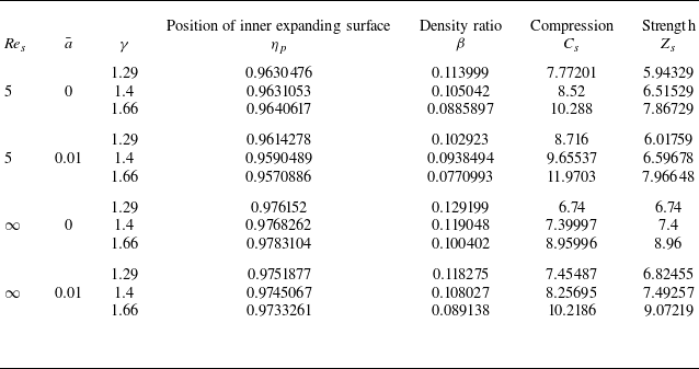
5.1. van der Waals gas with pressure correction and increasing ambient density
The density, radial velocity and pressure increase in non-viscous flow, as one moves from the shock front to the piston. In viscous flow, density decreases while radial velocity increases in the absence of heat flux, but in the presence of heat flux, radial velocity depends on non-idealness effect (see figures 2 a, 2 b and 2 d). The tangential velocity decreases in non-viscous flow but increases in viscous flow (see figure 2 c). The heat flux (see figure 2 e) and tangential viscous stress decrease (see figure 2 f), as one moves from the shock front to the piston. In the presence of viscosity and heat flux, the pressure and normal viscous stress attain maxima, and then decrease as one proceeds to the piston or inner expanding surface (see figures 2 d and 2 g). Adiabatic compressibility has the opposite behaviour to that of pressure and normal viscous stress (see figure 2 h). These observations are valid for the viscosity dependent on temperature only.
For the viscosity dependent on temperature and density, the pressure (see figure 3 d) and normal viscous stress (see figure 3 g) have a sharp increase near the piston in the absence of heat conduction, as one moves from the shock front to the piston. The adiabatic compressibility is opposite to this (see figure 3 h). The pattern of other observations is similar to those in figure 2.
The inclusion of pressure correction reveals new mechanisms governing shock strength, compression and viscous dissipation in self-similar flows, demonstrating that idealized models underestimate pressure buildup in dense-gas environments. The effects of individual flow parameters on the distribution of flow variables will be discussed in the following subsections.
Variation of reduced flow variables with pressure correction $\bar {a}$
, shock Reynolds number
$\bar {a}$
, shock Reynolds number $\textit{Re}_s$
and heat conduction
$\textit{Re}_s$
and heat conduction $\varGamma _c$
in a non-ideal gas (
$\varGamma _c$
in a non-ideal gas ( $\bar {b}=0$
) for
$\bar {b}=0$
) for $M^2=6$
,
$M^2=6$
, $a_c =2$
and
$a_c =2$
and $b_c =0$
behind the shock front:
$b_c =0$
behind the shock front: $(a)$
density,
$(a)$
density, $(b)$
radial velocity,
$(b)$
radial velocity, $(c)$
tangential velocity,
$(c)$
tangential velocity, $(d)$
pressure,
$(d)$
pressure, $(e)$
heat flux,
$(e)$
heat flux, $(f)$
tangential stress,
$(f)$
tangential stress, $(g)$
normal stress,
$(g)$
normal stress, $(h)$
adiabatic compressibility. The solid line (
$(h)$
adiabatic compressibility. The solid line ( ) denotes $\bar {a}=0.01$
, dot–dashed line (
$\bar {a}=0.01$
, dot–dashed line ( )
) $\bar {a}=0.0063$
and dotted line (
$\bar {a}=0.0063$
and dotted line ( ) ideal gas $(\bar {a}=0)$
;
$(\bar {a}=0)$
; $(1)\,\bar{a}=0,\textit{Re}_s = \infty ,\varGamma _c=0,$ $(2)\,\bar {a}={0.0063},\textit{Re}_s = \infty,\varGamma _c=0,$ $(3)\,\bar {a}=0.01,\textit{Re}_s = \infty,\varGamma _c=0,$ $(4)\,\bar {a}=0, \textit{Re}_s = 5,\varGamma _c=0,$ $(5)\,\bar {a}=0.0063,\textit{Re}_s = 5,\varGamma _c=0,$ $(6)\,\bar {a}=0.01,\textit{Re}_s = 5,\varGamma _c=0,$ $(7)\,\bar {a}=0,\textit{Re}_s = \infty, \varGamma _c=3,$ $(8)\,\bar {a}={0.0063},\textit{Re}_s = \infty,\varGamma _c=3,$ $(9)\,\bar {a}=0.01,\textit{Re}_s = \infty,\varGamma _c=3,$ $(10)\,\bar {a}=0,\textit{Re}_s = 5,\varGamma _c=3,$ $(11)\,\bar {a}=0.0063,\textit{Re}_s = 5,\varGamma _c=3,$ $(12)\,\bar {a}=0.01,\textit{Re}_s = 5,\varGamma _c=3$
.
$(12)\,\bar {a}=0.01,\textit{Re}_s = 5,\varGamma _c=3$
.
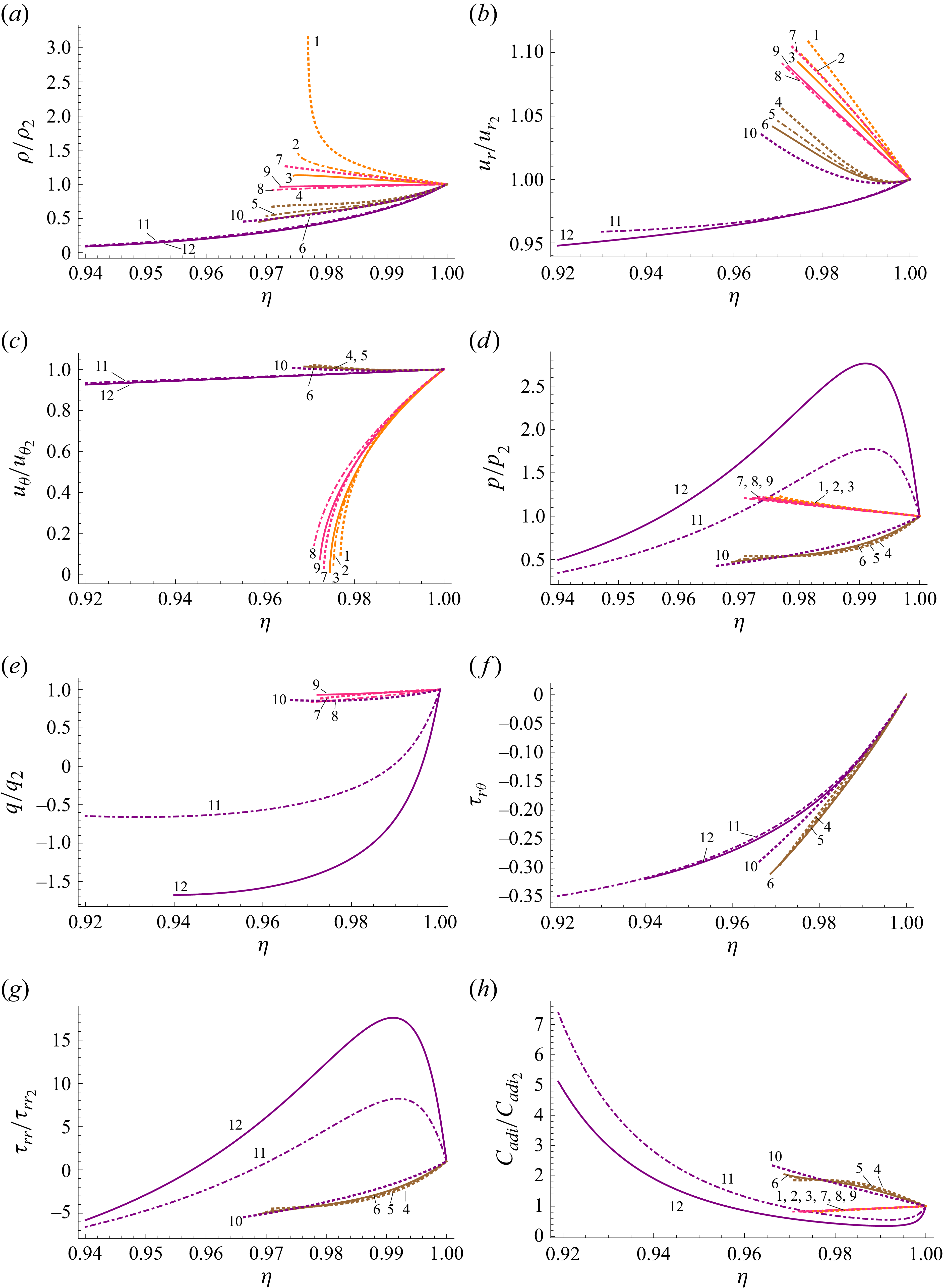
Variation of reduced flow variables with pressure correction $\bar {a}$
, heat conduction
$\bar {a}$
, heat conduction $\varGamma _c$
and viscosity index
$\varGamma _c$
and viscosity index $a_c\, \text{and}\, b_c$
in a non-ideal gas (
$a_c\, \text{and}\, b_c$
in a non-ideal gas ( $\bar {b}=0$
) for
$\bar {b}=0$
) for $M^2=6$
and
$M^2=6$
and $\textit{Re}_s =5$
behind the shock front:
$\textit{Re}_s =5$
behind the shock front: $(a)$
density,
$(a)$
density, $(b)$
radial velocity,
$(b)$
radial velocity, $(c)$
tangential velocity,
$(c)$
tangential velocity, $(d)$
pressure,
$(d)$
pressure, $(e)$
heat flux,
$(e)$
heat flux, $(f)$
tangential stress,
$(f)$
tangential stress, $(g)$
normal stress,
$(g)$
normal stress, $(h)$
adiabatic compressibility. The solid line (
$(h)$
adiabatic compressibility. The solid line ( ) denotes $\bar {a}=0.01$
and dotted line (
$\bar {a}=0.01$
and dotted line ( ) ideal gas $(\bar {a}=0)$
;
$(\bar {a}=0)$
; $(1)\,\bar {a}=0, \varGamma _c=0$
,
$(1)\,\bar {a}=0, \varGamma _c=0$
, $a_c =2$
,
$a_c =2$
, $b_c =0$
,
$b_c =0$
, $(2)\,\bar {a}= {0.01},\, \varGamma _c=0$
,
$(2)\,\bar {a}= {0.01},\, \varGamma _c=0$
, $a_c =2$
,
$a_c =2$
, $b_c =0$
,
$b_c =0$
, $(3)\, \bar {a}=0,\, \varGamma _c=3$
,
$(3)\, \bar {a}=0,\, \varGamma _c=3$
, $a_c =2$
,
$a_c =2$
, $b_c =0$
,
$b_c =0$
, $(4)\, \bar {a}=0.01, \varGamma _c=3$
,
$(4)\, \bar {a}=0.01, \varGamma _c=3$
, $a_c =2$
,
$a_c =2$
, $b_c =0$
,
$b_c =0$
, $(5),\, \bar {a}=0,\, \varGamma _c=0$
,
$(5),\, \bar {a}=0,\, \varGamma _c=0$
, $a_c =5/3$
,
$a_c =5/3$
, $b_c =1/3$
,
$b_c =1/3$
, $(6)\, \bar {a}=0.01,\, \varGamma _c=0$
,
$(6)\, \bar {a}=0.01,\, \varGamma _c=0$
, $a_c =5/3$
,
$a_c =5/3$
, $b_c =1/3$
,
$b_c =1/3$
, $(7)\, \bar {a}=0,\, \varGamma _c=3$
,
$(7)\, \bar {a}=0,\, \varGamma _c=3$
, $a_c =5/3$
,
$a_c =5/3$
, $b_c =1/3$
,
$b_c =1/3$
, $(8)\, \bar {a}= {0.01},\, \varGamma _c=3$
,
$(8)\, \bar {a}= {0.01},\, \varGamma _c=3$
, $a_c =5/3$
,
$a_c =5/3$
, $b_c =1/3$
.
$b_c =1/3$
.

5.1.1. Effect of increase of non-idealness parameter $\bar {a}$

The increase in non-idealness parameters $\bar {a}$
corresponds to either the increase in intermolecular attraction
$\bar {a}$
corresponds to either the increase in intermolecular attraction $`a$
’ or a decrease in the ambient tangential velocity
$`a$
’ or a decrease in the ambient tangential velocity $B^*\varOmega$
(see (4.25)). The following are the effects of increase of non-idealness parameters
$B^*\varOmega$
(see (4.25)). The following are the effects of increase of non-idealness parameters $\bar {a}$
(due to the intermolecular attraction
$\bar {a}$
(due to the intermolecular attraction $a$
).
$a$
).
-
(i) A decrement in density ratio
$\rho _1/\rho _2$
, an increment into shock compression
$C_s$
, the distance
$(1-\eta _p)$
between piston and shock and strength
$Z_s$
. The shock strength
$Z_s$
decreases with
$\bar {a}$
when viscosity varies with temperature and density both (see table 1). The density ratio
$\beta$
coincides with Patel & Pandey (Reference Patel and Pandey2024) for
$M=5$
and
$\bar {a}=\bar {b}=0$
. -
(ii) A decrement in
$\rho /\rho _2$
,
$u_r/u_{r_2}$
and
$q/q_2$
, (see figures 2
a, 2
b and 2
e); an increment in
$u_{\theta }/u_{\theta _2}$
in non-viscous flow but a decrement in viscous flow (see figure 2
c). -
(iii) An increment in
$p/p_2$
,
$\tau _{r\theta }$
and
$\tau _{\textit{rr}}/\tau _{rr_2}$
in viscous flow but in non-viscus flow
$p/p_2$
decreases (see figures 2
d, 2
f and 2
g);
$C_{\textit{adi}}/C_{adi,2}$
behaves opposite to that of pressure (see figure 2
h).


An increase in the pressure-correction parameter enhances mass accumulation behind the shock, reducing compressibility and hence lowering density and radial velocity, while simultaneously increasing pressure and viscous stresses. Contrary to Liu et al. (Reference Liu, Liu, Fu and Zhou2021), the present study shows that compressibility remains constant with pressure corrections with individual presence or absence of viscosity and heat conduction but decreases when both are present.
Variation of reduced flow variables with pressure correction $\bar {a}$
, specific heats ratio
$\bar {a}$
, specific heats ratio $\gamma$
and shock Reynolds number
$\gamma$
and shock Reynolds number $\textit{Re}_s$
in a non-ideal gas (
$\textit{Re}_s$
in a non-ideal gas ( $\bar {b}=0$
) for
$\bar {b}=0$
) for $M^2=6$
,
$M^2=6$
, $\varGamma _c =0$
,
$\varGamma _c =0$
, $a_c =2$
and
$a_c =2$
and $b_c =0$
behind the shock front:
$b_c =0$
behind the shock front: $(a)$
density,
$(a)$
density, $(b)$
radial velocity,
$(b)$
radial velocity, $(c)$
tangential velocity,
$(c)$
tangential velocity, $(d)$
pressure. The solid line (
$(d)$
pressure. The solid line ( ) represent non-ideal gas $(\bar {a}=0.01)$
and dashed line (
$(\bar {a}=0.01)$
and dashed line ( ) ideal gas $(\bar {a}=0)$
;
$(\bar {a}=0)$
; $(1) \, \bar {a}=0,\, \textit{Re}_s=\infty ,\, \gamma =1.29$
,
$(1) \, \bar {a}=0,\, \textit{Re}_s=\infty ,\, \gamma =1.29$
, $(2)\, \bar {a}=0, \textit{Re}_s=\infty ,\, \gamma =1.4,$ $(3)\, \bar {a}=0, \textit{Re}_s=\infty, \gamma =1.66,$ $(4)\, \bar {a}=0.01,\, {\textit{Re}_s=\infty },\, \gamma =1.29,$ $(5)\, \bar {a} =0.01, \textit{Re}_s=\infty , \gamma =1.4,$ $(6)\, \bar {a}=0.01,\, \textit{Re}_s=\infty ,\, \gamma =1.66,$ $(7)\, \bar {a}=0,\, \textit{Re}_s=5, \gamma =1.29,$ $(8)\, \bar {a}=0,\, \textit{Re}_s=5, \gamma =1.4,$ $(9)\, \bar {a}=0, \textit{Re}_s=5,\, \gamma =1.66,$ $(10)\, \bar {a}=0.01,\, \textit{Re}_s=5,\, \gamma =1.29,$ $(11)\, \bar {a}=0.01,\, \textit{Re}_s=5,\, \gamma =1.4,$ $(12)\, \bar {a}={} 0.01,\,\textit{Re}_s=5, \gamma =1.66$
.
$(12)\, \bar {a}={} 0.01,\,\textit{Re}_s=5, \gamma =1.66$
.

5.1.2. Effect of decrease of shock Reynolds numbers
$\textit{Re}_s$

The shock Reynolds number compares the role of inertial force with the viscous force and is significant in a boundary layer and close to interfaces. The decrease in value of shock Reynolds number corresponds to an increase in viscosity and pressure correction for a given reference state and has the following effects.
-
(i) A decrement in density ratio
$\rho _1/\rho _2$
and in the shock strength
$Z_s$
but an increment in shock compression
$C_s$
, and the distance
$(1-\eta _p)$
between the piston and shock (see tables 1 and 2). -
(ii) A decrement in
$\rho /\rho _2$
,
$u_r/u_{r_2}$
and
$q/q_2$
(see figures 2
a, 2
b, 4
a, 4
b and 2
e). -
(iii) An increment in
$u_{\theta }/u_{\theta _2}$
(see figures 2
c and 4
c). -
(iv) A decrement in
$p/p_2$
in the absence of heat conduction but an increment in the presence of heat conduction and pressure correction
$\bar {a}$
(see figures 2
d and 4
d);
$C_{\textit{adi}}/C_{adi_2}$
behaves opposite to that of pressure (see figure 2
h).


The viscous stress corresponds to a high velocity gradient particularly near the piston and shock front. On the other hand, decrease in shock Reynolds number $\textit{Re}_s$
corresponds to the increase in viscosity that introduces irreversible momentum dissipation, which weakens the shock strength but enhances the shock compression and separation between shock and piston.
$\textit{Re}_s$
corresponds to the increase in viscosity that introduces irreversible momentum dissipation, which weakens the shock strength but enhances the shock compression and separation between shock and piston.
5.1.3. Effect of an increase of heat conductive parameters
$\varGamma _c$

The heat conductive parameter $\varGamma _c$
depends on the thermal conductivity
$\varGamma _c$
depends on the thermal conductivity $K_0$
of the reference state and shock radius exponent
$K_0$
of the reference state and shock radius exponent $\sigma$
. The effect of
$\sigma$
. The effect of $\varGamma _c$
can be summarized as follows.
$\varGamma _c$
can be summarized as follows.
-
(i) An increment in the distance
$(1-\eta _p)$
between the piston and shock but density ratio
$\beta$
, shock compression
$C_s$
and strength
$Z_s$
remain same (see table 1). -
(ii) A decrement in
$\rho /\rho _2$
and
$u_r/u_{r_2}$
(see figures 2
a, 2
b, 3
a and 3
b); an increment in
$u_{\theta }/u_{\theta _2}$
in non-viscous flow but a decrement in viscous flow (see figure 2
c and 3
c). -
(iii) An increment in
$p/p_2$
,
$\tau _{\textit{rr}}/\tau _{rr_2}$
and
$\tau _{r\theta }$
in viscous flow (see figures 2
d, 2
f, 2
g and 3
h);
$C_{\textit{adi}}/C_{adi,2}$
exhibits an opposite trend to
$p/p_2$
(see figures 2
h and 3
h).


On inclusion of heat conduction along with viscosity in a pressure-corrected vdW gas, thermal energy generated by viscous dissipation redistributes behind the shock, leading to the coupling of thermal transport, viscous and non-ideal gas effects producing the above effects.
5.1.4. Effect of changing temperature-dependent viscosity to temperature- and density-dependent viscosity
The exponents $a_c$
and
$a_c$
and $b_c$
of temperature- and density-dependent viscosity enters into the system of governing equations ((4.40)–(4.46)) and boundary conditions ((4.47)–(4.49)). The inclusion of density dependent viscosity in addition to temperature dependent has the following effects on the shock dynamics.
$b_c$
of temperature- and density-dependent viscosity enters into the system of governing equations ((4.40)–(4.46)) and boundary conditions ((4.47)–(4.49)). The inclusion of density dependent viscosity in addition to temperature dependent has the following effects on the shock dynamics.
-
(i) A decrement in density ratio and shock strength
$Z_s$
but an increment in shock compression
$C_s$
(see table 1); an increment in the distance
$1-\eta _p$
for
$\varGamma _c =0$
, but for
$\varGamma _c =3$
an increment in ideal gas but a decrement in non-ideal gas (see table 1). -
(ii) A decrement in
$\rho /\rho _2$
,
$u_r/u_{r_2}$
,
$u_{\theta }/u_{\theta _2}$
and
$q/q_2$
(see figures 3
a, 3
b, 3
c and 3
e). -
(iii) A decrement in
$p/p_2$
for
$\varGamma _c =0$
, but for
$\varGamma _c =3$
a decrement in ideal gas but an increment in non-ideal gas (see figure 3
d). -
(iv) A decrement in
$\tau _{r\theta }$
(see figure 3
f); an increment in
$\tau _{\textit{rr}}/\tau _{rr_2}$
for
$\varGamma _c =0$
but for
$\varGamma _c =3$
it depends on pressure correction
$\bar {a}$
and position
$\eta$
and (see figure 3
g). -
(v) Here
$C_{\textit{adi}}/C_{adi_2}$
is opposite to that of
$p/p_2$
(see figure 3
h).


Introduction of density dependent viscosity strengthens viscous effects in the high-density region and coupled with heat conduction and non-idealness parameters significantly modifies the distribution of flow variables behind the shock.
5.1.5. Effect of increase of ratio of specific heats
$\gamma$

Following are the effects of increase of ratio of specific heats $\gamma$
.
$\gamma$
.
-
(i) A decrement in density ratio
$\beta$
but an increment in shock compression
$C_s$
and strength
$Z_s$
(see table 2). -
(ii) A decrement in the distance
$(1-\eta _p)$
between the piston and shock front in ideal gas but an increment in non-ideal gas (see table 2). -
(iii) A decrement in
$\rho /\rho _2$
and
$u_r/u_{r_2}$
(see figures 4
a and 4
b). -
(iv) An increment in
$p/p_2$
in non-viscous flow for ideal gas but a decrement in pressure corrected gas and viscous flow (see figure 4
d); but
$u_{\theta }/u_{\theta _2}$
depends on position
$\eta$
(see figure 4
c).


The increase in specific heat ratio bring the decrement in the adiabatic compressibility of the shocked gas which leads to the above observations.
5.2. van der Waals gas with volume correction and constant ambient density
As one moves from the shock front to the piston, the radial velocity (see figure 5 b) increases in both viscous and non-viscous flow, while tangential velocity (see figure 5 c) and heat flux (figure 5 e) decrease in non-viscous but increase in viscous flow. The density (see figure 5 a) and pressure (see figure 5 d) increase in non-viscous flow, but in viscous flow, density, pressure and normal viscous stress (see figure 5 g) depend on heat conduction and volume correction of gas. The tangential stress (see figure 5 f) decreases as one moves from the shock front to the piston. The adiabatic compressibility follows the opposite trend to that of pressure (see figure 5 h). All the above observations are valid for viscosity dependent on temperature only.
Variation of reduced flow variables with volume correction $\bar {b}$
, shock Reynolds number
$\bar {b}$
, shock Reynolds number $\textit{Re}_s$
and heat conduction
$\textit{Re}_s$
and heat conduction $\varGamma _c$
in a non-ideal gas
$\varGamma _c$
in a non-ideal gas $(\bar {a}=0)$
for
$(\bar {a}=0)$
for $M^2=6 , \, a_c =1, \text{and}\, b_c =0$
behind the shock front:
$M^2=6 , \, a_c =1, \text{and}\, b_c =0$
behind the shock front: $(a)$
density,
$(a)$
density, $(b)$
radial velocity,
$(b)$
radial velocity, $(c)$
tangential velocity,
$(c)$
tangential velocity, $(d)$
pressure,
$(d)$
pressure, $(e)$
heat flux,
$(e)$
heat flux, $(f)$
tangential stress,
$(f)$
tangential stress, $(g)$
normal stress,
$(g)$
normal stress, $(h)$
adiabatic compressibility. The solid line (
$(h)$
adiabatic compressibility. The solid line ( ) denotes $\bar {b}=0.025$
, dot–dashed line (
$\bar {b}=0.025$
, dot–dashed line ( )
) $\bar {b}=0.01$
and dotted line (
$\bar {b}=0.01$
and dotted line ( ) ideal gas $(\bar {b}=0)$
;
$(\bar {b}=0)$
; $(1)\, \bar {b}=0,\, \textit{Re}_s = \infty ,\,\varGamma _c=0,$ $(2) \, \bar {b} = {0.0015},\, \textit{Re}_s = \infty ,\, \varGamma _c=0,$ $(3)\, \bar {b} = {0.01},\, \textit{Re}_s = \infty ,\, \varGamma _c=0,$ $(4) \, \bar {b}=0.025,\, \textit{Re}_s = \infty ,\, \varGamma _c=0,$ $(5) \, \bar {b}=0,\, \textit{Re}_s = 5, \varGamma _c=0,$ $(6) \, \bar {b}=0.0015, \textit{Re}_s = 5, \varGamma _c=0,$ $(7) \, \bar {b}=0.01,\, \textit{Re}_s = 5, \varGamma _c=0,$ $(8) \, \bar {b}= 0.025, \textit{Re}_s = 5,\, \varGamma _c=0,$ $(9)\, \bar {b}=0,\, \textit{Re}_s = \infty , \varGamma _c=3,$ $(10) \,\bar {b}= {0.0015}, \textit{Re}_s = \infty , \varGamma _c=3,$ $(11)\, \bar {b} = {0.01},\, \textit{Re}_s = \infty ,\, \varGamma _c=3,$ $(12) \, \bar {b}=0.025, \textit{Re}_s = \infty , \varGamma _c=3,$ $(13) \, \bar {b}=0,\, \textit{Re}_s = 5, \varGamma _c=3,$ $(14) \, \bar {b}=0.0015,\, \textit{Re}_s = 5, \varGamma _c=3,$ $(15) \, \bar {b}=0.01,\, \textit{Re}_s = 5, \varGamma _c=3,$ $(16) \, \bar {b}=0.025,\, \textit{Re}_s = 5,\, \varGamma _c=3.$

Variation of reduced flow variables with volume correction $\bar {b}$
, heat conduction
$\bar {b}$
, heat conduction $\varGamma _c$
and
$\varGamma _c$
and $b_c$
in a non-ideal gas
$b_c$
in a non-ideal gas $(\bar {a}=0)$
for
$(\bar {a}=0)$
for $M^2=6$
,
$M^2=6$
, $\textit{Re}_s =5$
and
$\textit{Re}_s =5$
and $a_c =1$
behind the shock front:
$a_c =1$
behind the shock front: $(a)$
density,
$(a)$
density, $(b)$
radial velocity,
$(b)$
radial velocity, $(c)$
tangential velocity,
$(c)$
tangential velocity, $(d)$
pressure,
$(d)$
pressure, $(e)$
heat flux,
$(e)$
heat flux, $(f)$
tangential stress,
$(f)$
tangential stress, $(g)$
normal stress,
$(g)$
normal stress, $(h)$
adiabatic compressibility. The solid line (
$(h)$
adiabatic compressibility. The solid line ( ) denotes non-ideal gas $(\bar {b}=0.01)$
and dashed line (
$(\bar {b}=0.01)$
and dashed line ( ) ideal gas $(\bar {b}=0)$
;
$(\bar {b}=0)$
; $(1)\, \bar {b}=0,\,\varGamma _c=0,$ $b_c =0$
,
$b_c =0$
, $(2) \,\bar {b}= {0.01},\, \varGamma _c=0,$ $b_c =0$
,
$b_c =0$
, $(3) \, \bar {b}=0,\, \varGamma _c=3,$ $b_c =0$
,
$b_c =0$
, $(4) \, \bar {b}=0.01, \varGamma _c=3,$ $b_c =0$
,
$b_c =0$
, $(5) \, \bar {b}=0,\, \varGamma _c=0,$ $b_c =1/3$
,
$b_c =1/3$
, $(6) \, \bar {b}=0.01,\, \varGamma _c=0,$ $b_c =1/3$
,
$b_c =1/3$
, $(7)\, \bar {b}=0,\, \varGamma _c=3$
,
$(7)\, \bar {b}=0,\, \varGamma _c=3$
, $b_c =1/3$
,
$b_c =1/3$
, $(8) \, \bar {b}= {0.01},\, \varGamma _c=3$
,
$(8) \, \bar {b}= {0.01},\, \varGamma _c=3$
, $b_c =1/3$
.
$b_c =1/3$
.

Variation of flow reduced variables with volume correction, specific heats ratio $\gamma$
and shock Reynolds number
$\gamma$
and shock Reynolds number $\textit{Re}_s$
in a non-ideal gas
$\textit{Re}_s$
in a non-ideal gas $(\bar {a}=0)$
for
$(\bar {a}=0)$
for $M^2=6 , \, a_c =1, \text{and}\, b_c =0$
behind the shock front:
$M^2=6 , \, a_c =1, \text{and}\, b_c =0$
behind the shock front: $(a)$
density,
$(a)$
density, $(b)$
radial velocity,
$(b)$
radial velocity, $(c)$
tangential velocity,
$(c)$
tangential velocity, $(d)$
pressure. The solid line (
$(d)$
pressure. The solid line ( ) represent non-ideal gas $(\bar {b}=0.01)$
and dashed line (
$(\bar {b}=0.01)$
and dashed line ( ) ideal gas $(\bar {b}=0)$
;
$(\bar {b}=0)$
; $(1)\,\bar {b}=0,\, \textit{Re}_s=\infty ,\, \gamma =1.29,$ $(2)\, \bar {b}=0,\, \textit{Re}_s=\infty ,\, \gamma =1.4,$ $(3)\, \bar {b}=0,\, \textit{Re}_s=\infty ,\, \gamma =1.66,$ $(4)\, \bar {b}=0.01,\, \textit{Re}_s=\infty ,\, \gamma =1.29,$ $(5)\, \bar {b}=0.01,\, \textit{Re}_s=\infty ,\, \gamma =1.4,$ $(6)\, \bar {b}=0.01,\, \textit{Re}_s=\infty ,\, \gamma =1.66,$ $(7)\, \bar {b}=0,\, \textit{Re}_s=5,\, \gamma =1.29,$ $(8)\, \bar {b}=0,\, \textit{Re}_s=5,\, \gamma =1.4,$ $(9)\, \bar {b}=0,\, \textit{Re}_s=5,\, \gamma =1.66,$ $(10)\, \bar {b}=0.01,\, \textit{Re}_s=5,\, \gamma =1.29,$ $(11)\, \bar {b}=0.01,\, \textit{Re}_s=5,\, \gamma =1.4,$ $(12)\, \bar {b}=0.01,\, \textit{Re}_s=5,\, \gamma =1.66$
.
$(12)\, \bar {b}=0.01,\, \textit{Re}_s=5,\, \gamma =1.66$
.

For the validation of the present study in non-viscous flow in vdW gas with volume correction $\bar {b}$
, we have compared our result with the results of Singh & Nath (Reference Singh and Nath2014), Nath & Sahu (Reference Nath and Sahu2017) and Bajargaan & Patel (Reference Bajargaan and Patel2018), and found that the radial and tangential velocity have similar flow patterns, as one moves from the shock front to the piston.
$\bar {b}$
, we have compared our result with the results of Singh & Nath (Reference Singh and Nath2014), Nath & Sahu (Reference Nath and Sahu2017) and Bajargaan & Patel (Reference Bajargaan and Patel2018), and found that the radial and tangential velocity have similar flow patterns, as one moves from the shock front to the piston.
We have found that the profiles of reduced density, radial velocity and pressure for viscous flow $\textit{Re}_s =5$
with constant viscosity have similar patterns as Patel & Pandey (Reference Patel and Pandey2024) in absence of heat conduction, and as Patel & Garg (Reference Patel and Garg2024) in the absence of a magnetic field in an ideal gas for an exponential planer shock wave, as one moves from the shock front to the piston. In all cases, the qualitative variation of flow variables from the shock front towards the piston is in good agreement with these earlier studies. The previous studies did not incorporate volume-correction effects in viscous flow. By extending the analysis to cylindrical symmetry with variable viscosity, the present model captures finite molecular volume effects on viscous shock propagation that were not accessible in earlier idealized viscous analyses (Patel & Garg Reference Patel and Garg2024; Patel & Pandey Reference Patel and Pandey2024).
$\textit{Re}_s =5$
with constant viscosity have similar patterns as Patel & Pandey (Reference Patel and Pandey2024) in absence of heat conduction, and as Patel & Garg (Reference Patel and Garg2024) in the absence of a magnetic field in an ideal gas for an exponential planer shock wave, as one moves from the shock front to the piston. In all cases, the qualitative variation of flow variables from the shock front towards the piston is in good agreement with these earlier studies. The previous studies did not incorporate volume-correction effects in viscous flow. By extending the analysis to cylindrical symmetry with variable viscosity, the present model captures finite molecular volume effects on viscous shock propagation that were not accessible in earlier idealized viscous analyses (Patel & Garg Reference Patel and Garg2024; Patel & Pandey Reference Patel and Pandey2024).
For the viscosity dependent on temperature and density, the density, pressure, normal and tangential viscous stresses and heat flux decrease, but radial and tangential velocities and adiabatic compressibility increases, as one moves from the shock front to the piston (see figure 6
a–h). The variation of density, velocity, and pressure with specific heat ratio $\gamma$
can be seen in figure 7 under temperature dependent viscosity coefficient. The effects of individual flow parameters on the distribution of flow variables will be discussed in the following subsections.
$\gamma$
can be seen in figure 7 under temperature dependent viscosity coefficient. The effects of individual flow parameters on the distribution of flow variables will be discussed in the following subsections.
5.2.1. Effect of increase of non-idealness parameter
$\bar {b}$

An increase in the non-idealness parameter $\bar {b}$
, which accounts for finite molecular volume, significantly affects shock propagation and the variation of flow variables. The increase in non-idealness parameters
$\bar {b}$
, which accounts for finite molecular volume, significantly affects shock propagation and the variation of flow variables. The increase in non-idealness parameters $\bar {b}$
as following effects.
$\bar {b}$
as following effects.
-
(i) An increment in density ratio
$(\rho _1/\rho _2)$
but a decrement in shock compression
$C_s$
and strength
$Z_s$
except the strength
$Z_s$
has an increment for density dependent viscosity (see table 3); an increment in density ratio is similar to Bajargaan & Patel (Reference Bajargaan and Patel2018) in non-viscous flow. -
(ii) An increment in the distance
$(1-\eta _p)$
between the piston and shock (see table 3); an increment in the distance
$(1-\eta _p)$
is also reported by Bajargaan & Patel (Reference Bajargaan and Patel2018) in non-viscous flow. -
(iii) An increment in
$q/q_2$
(see figure 5
e); a decrement in
$\rho /\rho _2$
and
$p/p_2$
(see figures 5
a and 5
d); a decrement in
$u_{r}/u_{r_2}$
but an increment for
$\textit{Re}_s =5, \varGamma _c =3$
(see figure 5
b);
$C_{\textit{adi}}/C_{{adi}_2}$
behaves opposite to that of
$p/p_2$
(see figure 5
h). -
(iv) An increment in
$u_{\theta }/u_{\theta _2}$
for non-viscous flow but a decrement for viscous flow (see figure 5
c); a decrement in
$\tau _{\textit{rr}}/\tau _{rr_2}$
near the piston (see figures 5
g); an increment
$\tau _{r \theta }$
(see figure 5
f).





The resulting change in adiabatic compressibility with $\bar {b}$
weakens the shock strength and produce the above distribution of the flow variables.
$\bar {b}$
weakens the shock strength and produce the above distribution of the flow variables.
Variation of the position of the inner expanding surface ( $\eta _p$
) density ratio (
$\eta _p$
) density ratio ( $\beta ={\rho _1}/{\rho _2}$
), shock compression
$\beta ={\rho _1}/{\rho _2}$
), shock compression $C_s$
and shock strength
$C_s$
and shock strength $Z_s$
across the shock front with
$Z_s$
across the shock front with $b_c$
,
$b_c$
, $\textit{Re}_s$
,
$\textit{Re}_s$
, $\bar {b}$
and
$\bar {b}$
and $\varGamma _c$
for
$\varGamma _c$
for $a_c=1$
,
$a_c=1$
, $\gamma = 1.4$
and
$\gamma = 1.4$
and $M^2=6$
.
$M^2=6$
.
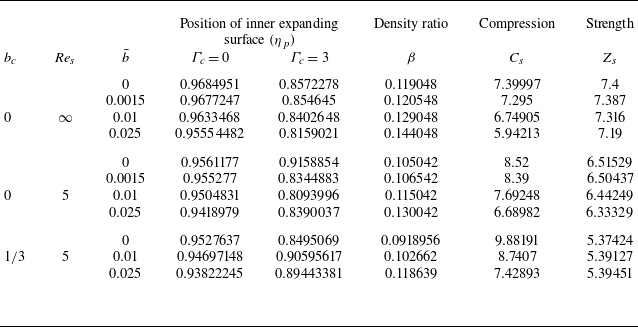
Variation of the position of the inner expanding surface $\eta _p$
, density ratio (
$\eta _p$
, density ratio ( $\beta ={\rho _1}/{\rho _2}$
), shock compression
$\beta ={\rho _1}/{\rho _2}$
), shock compression $C_s$
and shock strength
$C_s$
and shock strength $Z_s$
across the shock front with
$Z_s$
across the shock front with $\textit{Re}_s$
,
$\textit{Re}_s$
, $\bar {b}$
and
$\bar {b}$
and $\gamma$
for
$\gamma$
for $\varGamma _c = 0$
,
$\varGamma _c = 0$
, $a_c =1$
,
$a_c =1$
, $b_c =0$
and
$b_c =0$
and $M^2 =6$
.
$M^2 =6$
.
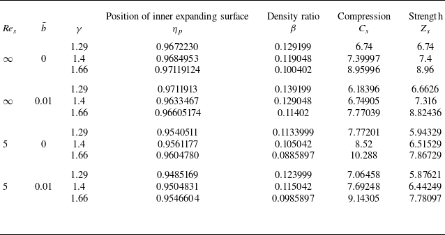
5.2.2. Effect of decrease of shock Reynolds numbers
$\textit{Re}_s$

The following effects of decrease in the value of shock Reynolds number $\textit{Re}_s$
correspond to an increase in viscosity but a decrease in volume correction for a given reference state.
$\textit{Re}_s$
correspond to an increase in viscosity but a decrease in volume correction for a given reference state.
-
(i) A decrement in density ratio
$\rho _1/\rho _2$
and in shock strength
$Z_s$
but an increment in shock compression
$C_s$
and the distance
$(1-\eta _p)$
between the piston and shock (see tables 3–4). -
(ii) A decrement in
$\rho /\rho _2$
,
$u_{r}/u_{r_2}$
and
$p/p_2$
but an increment in
$u_\theta /u_{\theta _2}$
and
$q/q_2$
(see figures 5 and 7);
$C_{\textit{adi}}/C_{adi_2}$
behaves opposite to that of
$p/p_2$
(see figure 5
h).


Viscosity introduces irreversible momentum diffusion that weakens shock strength and density ratio but strengthens the shock compression and separation between the shock and piston. The momentum dissipation due to viscosity leads to the above characteristic of the flow variables.
5.2.3. Effect of an increase of heat conductive parameters
$\varGamma _c$

Following are the effects of an increase of heat conductive parameters $\varGamma _c$
.
$\varGamma _c$
.
-
(i) An increment in distance (
$1-\eta _p$
) but the shock compression
$C_s$
and strength
$Z_s$
are independent from heat conductive parameters
$\varGamma _c$
(see table 3). -
(ii) A decrement in
$\rho /\rho _2$
and
$u_{r}/u_{r_2}$
(see figures 5
a 5
b, 6
a and 6
b); an increment in
$u_{\theta }/u_{\theta _2}$
for non-viscous but a decrement in viscous flow (see figures 5
c and 6
c). -
(iii) A decrement in
$p/p_2$
for
$\textit{Re}_s=\infty$
but an increment in
$p/p_2$
,
$\tau _{r\theta }$
and
$\tau _{\textit{rr}}/\tau _{rr_2}$
for
$\textit{Re}_s=5$
near the shock (see figures 5
d, 5
f, 5
g, 6
e, 6
g and 6
h);
$C_{\textit{adi}}/C_{adi_2}$
behave opposite to that of pressure (see figures 5
h and 6
h).


The heat-conductive parameter $\varGamma _c$
enhances thermal energy diffusion behind the shock without altering the shock jump conditions. The redistribution of thermal energy smooths the temperature gradient and reduces the local pressure gradients. This weakens the coupling between the piston and the shocked gas, leading to an increase in the piston–shock separation.
$\varGamma _c$
enhances thermal energy diffusion behind the shock without altering the shock jump conditions. The redistribution of thermal energy smooths the temperature gradient and reduces the local pressure gradients. This weakens the coupling between the piston and the shocked gas, leading to an increase in the piston–shock separation.
5.2.4. Effect of changing temperature-dependent viscosity to temperature- and density-dependent viscosity
The inclusion of density dependent viscosity in addition to temperature has the following effects on the shock dynamics.
-
(i) A decrement in density ratio
$\beta$
and shock strength
$Z_s$
but an increment in shock compression
$C_s$
(see table 3). -
(ii) An increment in the distant (
$1-\eta _p$
) between the piston and shock for
$\varGamma _c =0$
, but a decrement for
$\varGamma _c =3$
(see table 3). -
(iii) A decrement in
$\rho /\rho _2$
,
$u_{r}/u_{r_2}$
,
$u_{\theta }/u_{\theta _2}$
,
$p/p_2$
and
$q/q_2$
(see figure 6
a to 6
e); an increment in
$\tau _{r\theta }$
and
$\tau _{\textit{rr}}/\tau _{rr_2}$
(see figures 6
f and 6
g).


The volume correction modifies the density and hence viscosity. When viscosity is allowed to depend on both temperature and density, its magnitude increases significantly in the compressed region behind the shock. Consequently, momentum diffusion and energy dissipation are intensified in this region. The enhanced dissipation reduces flow velocities, pressure, heat flux and shock strength, while simultaneously increasing the overall shock compression due to greater resistance to flow acceleration. The coupling between viscosity and density also amplifies viscous stresses, highlighting the importance of density effects in viscous shock propagation.
5.2.5. Effect of increase of ratio of specifics heats
$\gamma$

The effects of increase of ratio of specific heats $\gamma$
can be summarized as follows.
$\gamma$
can be summarized as follows.
-
(i) A decrement in density ratio
$\beta$
but an increment in shock compression
$C_s$
and strength
$Z_s$
(see table 4). -
(ii) A decrement in distance between the piston and shock front
$(1-\eta _p)$
but an increment in non-ideal gas for non-viscous flow (see table 4). -
(iii) An increment in
$\rho /\rho _2$
and
$p/p_2$
but a decrement in
$u_r/u_{r_2}$
(see figures 7); a decrement
$u_{\theta }/u_{\theta _2}$
in non-viscous flow but an increment in viscous flow (see figures 7).


Increasing the ratio of specific heats $\gamma$
reduces the compressibility of the gas. Consequently, the density jump across the shock decreases, while the pressure increases, leading to enhanced shock strength and compression. Behind the shock, the reduced compressibility weakens flow acceleration, decreasing velocities in non-viscous flow.
$\gamma$
reduces the compressibility of the gas. Consequently, the density jump across the shock decreases, while the pressure increases, leading to enhanced shock strength and compression. Behind the shock, the reduced compressibility weakens flow acceleration, decreasing velocities in non-viscous flow.
5.3. Notes on pressure and volume correction in vdW gas
In pressure corrected vdW gas, the boundary layer exists in reduced pressure, normal viscous stress and heat flux near the shock front $(\eta =1)$
in the presence of viscosity and heat conduction both. This boundary layer is due to increased intermolecular interaction between the molecules of the gas and a decrease in the adiabatic compressibility. The boundary layer may influence the stability of an object attached with the shock. However, for the viscosity dependent on temperature and density both, the boundary layer exists near the piston
$(\eta =1)$
in the presence of viscosity and heat conduction both. This boundary layer is due to increased intermolecular interaction between the molecules of the gas and a decrease in the adiabatic compressibility. The boundary layer may influence the stability of an object attached with the shock. However, for the viscosity dependent on temperature and density both, the boundary layer exists near the piston $(\eta = \eta _p$
) in addition to the shock front in pressure, normal viscous stress and adiabatic compressibility in the absence of heat conduction. The boundary layer near the inner expanding surface will modify the impact of the surface on overall shock dynamics. It is a qualitative observation and needs a detailed quantitative investigation and experimental support. The shocked gas becomes denser near the piston
$(\eta = \eta _p$
) in addition to the shock front in pressure, normal viscous stress and adiabatic compressibility in the absence of heat conduction. The boundary layer near the inner expanding surface will modify the impact of the surface on overall shock dynamics. It is a qualitative observation and needs a detailed quantitative investigation and experimental support. The shocked gas becomes denser near the piston $(\eta =\eta _p)$
in the vdW gas with volume correction as compared with that in pressure correction (see figures 2
a and 5
a). There is a significant difference in the distribution of flow variables with respect to viscosity dependent on temperature only and viscosity dependent on temperature as well as density (see figures 3 and 6). This shows the importance of density-dependent viscosity. The pressure and volume correction has a significant difference in distribution of flow variables (see figures 2 and 5). The ratio of specifics heats contributes more in non-viscous vdW gas with volume correction (see figures 4 and 7).
$(\eta =\eta _p)$
in the vdW gas with volume correction as compared with that in pressure correction (see figures 2
a and 5
a). There is a significant difference in the distribution of flow variables with respect to viscosity dependent on temperature only and viscosity dependent on temperature as well as density (see figures 3 and 6). This shows the importance of density-dependent viscosity. The pressure and volume correction has a significant difference in distribution of flow variables (see figures 2 and 5). The ratio of specifics heats contributes more in non-viscous vdW gas with volume correction (see figures 4 and 7).
The novelty of the present study lies in incorporating both the pressure and volume corrections of the vdW gas into the analysis of self-similar solutions for cylindrically symmetric flow. To the best of our knowledge, the pressure correction has not previously been considered simultaneously in non-viscous and viscous flows for variable viscosity coefficient. The volume correction in viscous flow has not been reported in the existing literature. The results obtained under these non-ideal conditions provide significant insights into shock dynamics in dissipative media and the foundation for improving shock modelling in real gases. In an earlier study (Patel & Pandey Reference Patel and Pandey2024), self-similar solutions with a constant viscosity coefficient in planar symmetry did not admit observable effects of pressure and volume corrections. This limitation motivated the present extension to cylindrical symmetry with a variable viscosity coefficient, where such non-ideal effects become admissible.
Furthermore, the present findings show qualitative agreement with previous numerical investigations of high-pressure and real-gas flows, where heat conduction and non-ideal effects significantly influence shock position, pressure distribution and flow structure (Jassim et al. Reference Jassim, Abdi and Muzychka2008a
,
Reference Jassim, Abdi and Muzychkab
; Kormann & Krüger Reference Kormann and Krüger2019; Yokozeki & Shiflett Reference Yokozeki and Shiflett2010; Avramenko et al. Reference Avramenko, Shevchuk, Kovetskaya and Kovetska2023a
). Using computational fluid dynamics simulations, Jassim et al. (Reference Jassim, Abdi and Muzychka2008a
) demonstrated that the shock position is strongly affected when the working gas is changed from an ideal-gas approximation to a real gas, such as when methane is replaced by nitrogen. Although methane is not considered in the present study, similar qualitative behaviour is observed: the distance between the piston and the shock front generally decreases for an ideal gas but increases for a non-ideal gas, when a polyatomic gas ( ${\textrm{CO}}_2$
) is changed to a monatomic gas (argon). Previous studies have also highlighted the sensitivity of heat transfer and pressure to real-gas effects. In particular, Avramenko et al. (Reference Avramenko, Shevchuk, Kovetskaya and Kovetska2023b
) reported that pressure correction reduces heat transfer, while volume correction amplifies deviations from ideal-gas behaviour; a similar trend is observed here in the variation of heat flux. Avramenko et al. (Reference Avramenko, Shevchuk, Kovetskaya and Kovetska2023a
) have studied non-viscous flow, and found that the pressure has a decrement with an increase in pressure-correction terms but an increment with an increase in volume correction when heat transfer is zero. In the present work for non-viscous flow, a similar observation is found in pressure-corrected vdW gas but the opposite in volume-corrected vdW gas in the absence of heat conduction. Importantly, the present formulation also allows the analysis of viscous flow, where pressure increases significantly with pressure correction but decreases with volume-correction parameters due to viscous dissipation effects that are not captured in non-viscous models. The present study provides indirect support for the validity of our theoretical model and highlights its relevance for realistic shock dynamics in dissipative media. Although direct experimental validation is beyond the scope of the present work, experimental–numerical studies such as Marty et al. (Reference Marty, Daniel, Massoni, Biamino, Houas, Leriche and Jourdan2019) have shown that shock strength and transmitted pressure can be reduced through geometric modifications of the duct. In addition, the present study shows that shock strength and pressure can be weakened or modified by the thermodynamic and dissipative properties of the gas, including viscosity, heat conduction and vdW gas effects.
${\textrm{CO}}_2$
) is changed to a monatomic gas (argon). Previous studies have also highlighted the sensitivity of heat transfer and pressure to real-gas effects. In particular, Avramenko et al. (Reference Avramenko, Shevchuk, Kovetskaya and Kovetska2023b
) reported that pressure correction reduces heat transfer, while volume correction amplifies deviations from ideal-gas behaviour; a similar trend is observed here in the variation of heat flux. Avramenko et al. (Reference Avramenko, Shevchuk, Kovetskaya and Kovetska2023a
) have studied non-viscous flow, and found that the pressure has a decrement with an increase in pressure-correction terms but an increment with an increase in volume correction when heat transfer is zero. In the present work for non-viscous flow, a similar observation is found in pressure-corrected vdW gas but the opposite in volume-corrected vdW gas in the absence of heat conduction. Importantly, the present formulation also allows the analysis of viscous flow, where pressure increases significantly with pressure correction but decreases with volume-correction parameters due to viscous dissipation effects that are not captured in non-viscous models. The present study provides indirect support for the validity of our theoretical model and highlights its relevance for realistic shock dynamics in dissipative media. Although direct experimental validation is beyond the scope of the present work, experimental–numerical studies such as Marty et al. (Reference Marty, Daniel, Massoni, Biamino, Houas, Leriche and Jourdan2019) have shown that shock strength and transmitted pressure can be reduced through geometric modifications of the duct. In addition, the present study shows that shock strength and pressure can be weakened or modified by the thermodynamic and dissipative properties of the gas, including viscosity, heat conduction and vdW gas effects.
6. Conclusions
The present study investigates the self-similar flow in a vdW gas undergoing solid-body rotation for a diverging exponential cylindrical shock wave, accounting with variable viscosity and heat conduction in temperature and density. It focuses on how different flow parameters influence shock strength, shock compression and the distribution of flow variables behind the shock front. The findings of this study lead to the following important conclusions.
-
(i) Self-similar solutions exist with increasing ambient density in pressure corrected vdW gas while in volume-corrected vdW gas solutions exist with constant ambient density. Further, the solution exists with viscosity dependent on temperature and density in coupled manner (
$a_c +b_c =2$
) in pressure-corrected vdW gas but in an uncoupled manner (
$a_c =1$
) for volume-corrected vdW gas. -
(ii) The shock weakens with increased viscosity, temperature and density dependent viscosity, and volume correction, but strengthens with pressure correction and specific heat ratio. Shock compression increases with pressure correction, viscosity and specific heat ratio, yet decreases as the volume-correction term increases.
-
(iii) Viscosity reduces density, radial velocity and heat flux while enhancing tangential velocity in pressure-corrected gas. Pressure response depends on the combined effects of pressure correction and heat conduction. Whereas in volume-corrected gas, viscosity reduces the density, radial velocity and pressure, but enhances the tangential velocity and heat flux.
-
(iv) Pressure correction (
$\bar {a}$
) decreases the density, radial velocity and heat flux but increases the pressure and viscous stresses in viscous flow regardless of heat conduction. Tangential velocity varies primarily with heat conduction. -
(v) Volume correction (
$\bar {b}$
) reduces density and pressure but enhanced the heat flux and tangential velocity. The variation of normal viscous stress depends on heat conduction. -
(vi) Heat conduction reduces the density and radial velocity while it increases pressure and viscous stresses under pressure correction. In volume corrected gas, heat conduction reduces the density, radial velocity and pressure but enhanced the tangential velocity and tangential viscous stress. The dependence of viscosity on both temperature and density significantly influences the behaviour of the flow variables behind the shock front.
-
(vii) The specific heat ratio (
$\gamma$
) reduces the density and radial velocity irrespective of viscosity, whereas the tangential velocity and pressure are influenced by viscosity in a pressure-corrected gas. On the other hand, in a volume-corrected vdW gas, the radial velocity decreases but density and pressure increase irrespective of viscosity but tangential velocity depend on viscosity. -
(viii) Total energy behind the shock wave is found to be proportional to the sixth power of the shock radius
$R(t)$
in vdW gas with pressure correction, while fourth power of
$R(t)$
in volume-corrected vdW gas.


Limitations and future scope. The present model assumes axisymmetry, solid-body rotation, variable transport coefficients in vdW gas, and excludes effects of radiation, chemical reactions, magnetic fields, molecular vibration, ionization, dissociation. Extending this framework to include more real-gas equations of state would provide deeper insight into high-pressure, high-density regimes relevant to astrophysical and engineering shock phenomena. Moreover, the self-similar solution considered here is a limiting case of more general non-self-similar flows and is restricted to the exponential law, which represents a special case of the broader class of power-law expansions. Future work may therefore include a systematic investigation of multiple scale analysis, near- and far-field features of shock dynamics, as well as validation of the present analytical results using high-resolution compressible flow solvers (Ling & Balachandar Reference Ling and Balachandar2018), in order to further assess the quantitative limits of applicability of the similarity framework.
Although this study focuses on diverging exponential cylindrical shocks, the analysis has potential experimental and practical relevance. It may help the design and optimization of systems operating under high-speed conditions and solid-body rotation where ambient density varies with time. Applications include ignition-delay processes in combustion, shock propagation in supernova or nuclear explosions and laboratory experiments such as exploding wires or high-speed hyperbolic flows relevant to meteors and re-entry vehicles (Hutchens Reference Hutchens1995).
Acknowledgements
The research of the second and corresponding author (A.P.) was supported by the University of Delhi, Delhi vide reference number /IoE/2024-25/12/FRP dated 30 August 2024. The research of the first author (K.P.) was supported by UGC, New Delhi, India vide NTA reference no. 211610049381 dated 19 April 2022. The authors thank the Associate Editor and the unknown reviewers for their constructive comments and suggestions.
Declaration of interests
The authors report no conflict of interest.
Data availability statement
The data that support the findings of this study are available from the corresponding author upon reasonable request.
Appendix A
This appendix deals with equivalence of inertial frame of reference with solid body rotation under ambient base state rotation and rotating frame of reference with rest base state. The two system under a perturbation yields same system of governing equations.
A.1.1. Inertial frame
Inertial frame of reference has two advantages: (i) conservation laws and Rankine–Hugoniot jump conditions take their simplest form there, and (ii) the physical piston is attached to the laboratory, and it moves only radially and has no circumferential motion in the laboratory. In the inertial formulation with solid body rotation (3.5), the system of equations are written in (3.1)–(3.4) and (3.7)–(3.9). The initial base state with solid-body rotation (Levin & Skopina Reference Levin and Skopina2004) is given by
 \begin{equation} u_{r_0} =0, \, u_{\theta _0}(r) = Ar, \rho _0, p_0 \, \text{such that pressure gradient} \frac {{\textrm d}p_0}{{\textrm d}r} = \rho _0 \frac {u^2_{\theta _0}}{r} = \rho _0 \varOmega ^2 r. \end{equation}
The base pressure gradient is balanced by the centrifugal force $\varOmega ^2r\rho _0$
. Equation (A1) expresses the radial equilibrium of the ambient swirling medium: the centripetal term
$\varOmega ^2r\rho _0$
. Equation (A1) expresses the radial equilibrium of the ambient swirling medium: the centripetal term $\rho _0 u^2_{\theta }/r$
is balanced by the pressure gradient. Such equilibrium are classical (Chandrasekhar (Reference Chandrasekhar2013), page. 274) and have been confirmed experimentally (Taylor Reference Taylor1923), validating the assumption of a pre-existing swirl field ahead of the shock. Moreover, the practice of prescribing pre-existing swirl or vortex fields ahead of shocks is well established in shock–vortex interaction studies in aerospace flows (e.g. Kandil, Kandil & Liu (Reference Kandil, Kandil and Liu1993)), which further supports the present modelling choice. Now, we consider the flow variables as a result of perturbation due to the piston in the base flow given by (Hopfinger Reference Hopfinger1992; Chandrasekhar Reference Chandrasekhar2013)
$\rho _0 u^2_{\theta }/r$
is balanced by the pressure gradient. Such equilibrium are classical (Chandrasekhar (Reference Chandrasekhar2013), page. 274) and have been confirmed experimentally (Taylor Reference Taylor1923), validating the assumption of a pre-existing swirl field ahead of the shock. Moreover, the practice of prescribing pre-existing swirl or vortex fields ahead of shocks is well established in shock–vortex interaction studies in aerospace flows (e.g. Kandil, Kandil & Liu (Reference Kandil, Kandil and Liu1993)), which further supports the present modelling choice. Now, we consider the flow variables as a result of perturbation due to the piston in the base flow given by (Hopfinger Reference Hopfinger1992; Chandrasekhar Reference Chandrasekhar2013)
 \begin{equation} \begin{aligned} u_r &= u^{\prime}_r(r,t), \, u_{\theta } = u_{\theta _{0}}(r) + u^{\prime}_{\theta }(r,t) = \varOmega r + u^{\prime}_{\theta }(r,t),\, \rho = \rho _0(r) + \rho ^{\prime}(r,t), \nonumber\\ p &= p_0(r) + p^{\prime}(r,t),\, \end{aligned} \end{equation}
where the primed quantities reflect the perturbations. Now, on applying these perturbations on system of (3.1)–(3.4) and (3.7)–(3.9) and considering the solid body rotation of gas, we obtain the following set of equations (Chandrasekhar (Reference Chandrasekhar2013), chapter $2$
):
$2$
):
 \begin{align} & \frac {\partial \rho ^{\prime}}{\partial t} +u^{\prime}_{r}\frac {\partial (\rho _0+\rho ^{\prime})}{\partial r} + (\rho _0+\rho ^{\prime})\frac {\partial u^{\prime}_{r}}{\partial r} +\frac {(\rho _0+ \rho )u^{\prime}_{r}}{r} =0, \end{align}
 \begin{align} & (\rho _0+\rho ^{\prime})\frac {\partial u^{\prime}_r }{\partial t } + \frac {\partial (p_0 +p^{\prime}) }{\partial r } - \frac {\partial \tau ^{\prime}_{\textit{rr}}}{\partial r}-\frac {2\mu }{r}\frac {u^{\prime}_{r}}{r}+\frac {2\mu }{ r}\frac {\partial u^{\prime}_{r}}{\partial r}- 2\varOmega u^{\prime}_{\theta }(\rho _0+\rho ^{\prime})\nonumber\\ & \quad -\varOmega ^2r(\rho _0 +\rho ^{\prime}) -\frac {u'^2_{\theta }(\rho _0+\rho ^{\prime})}{r}=0 , \end{align}
 \begin{align} & (\rho _0+\rho ^{\prime})\frac {\partial u^{\prime}_{\theta }}{\partial t}+ (\rho _0+\rho ^{\prime})u^{\prime}_r\frac {\partial u^{\prime}_{\theta }}{\partial t}-\frac {\partial \tau ^{\prime}_{r\theta }}{\partial r} -\frac {2\tau ^{\prime}_{r\theta }}{ r}+2\varOmega (\rho _0+\rho ^{\prime}) u^{\prime}_r+\frac {(\rho _0+\rho ^{\prime})u^{\prime}_{\theta }u^{\prime}_r}{r}=0, \end{align}
 \begin{align} \tau ^{\prime}_{\textit{rr}} & =\mu \left [\frac {4}{3}\frac {\partial u^{\prime}_r}{\partial r}-\frac {2}{3}\frac {u^{\prime}_{r}}{r}\right ] =\tau _{\textit{rr}},\, \tau ^{\prime}_{r\theta }= \mu \left [\frac {\partial u^{\prime}_{\theta }}{\partial r}-\frac {u^{\prime}_{\theta }}{r}\right ]=\tau _{r\theta }, \nonumber\\ \quad \tau ^{\prime}_{\theta \theta } & = \mu \left [\frac {4}{3}\frac {u^{\prime}_{r}}{r}-\frac {2 }{3}\frac {\partial u^{\prime}_r}{\partial r}\right ]=\tau _{\theta \theta }. \end{align}
When one perturbs the inertial (3.1)–(3.4) and (3.7)–(3.9) about rotating base state (A1) the convective/geometric terms $\rho u_{\theta }^2/r+$
produce the same radial–azimuthal coupling that an explicit Coriolis acceleration
$\rho u_{\theta }^2/r+$
produce the same radial–azimuthal coupling that an explicit Coriolis acceleration $-2\varOmega u_{\theta }$
and
$-2\varOmega u_{\theta }$
and $2\varOmega u_{r}$
, and centrifugal acceleration
$2\varOmega u_{r}$
, and centrifugal acceleration $\varOmega ^2r$
would be present in a rotating frame; specifically the perturbed momentum equations. The oscillatory coupling between radial and azimuthal velocity perturbations is usually explained by the Coriolis force when one writes the equations in a rotating frame. But in the inertial-frame formulation, the same coupling shows up automatically from the base swirl velocity after perturbation.
$\varOmega ^2r$
would be present in a rotating frame; specifically the perturbed momentum equations. The oscillatory coupling between radial and azimuthal velocity perturbations is usually explained by the Coriolis force when one writes the equations in a rotating frame. But in the inertial-frame formulation, the same coupling shows up automatically from the base swirl velocity after perturbation.
A.1.2. Rotating frame
In a rotating frame, one must need to introduce Coriolis and centrifugal forces in the momentum equation. The Coriolis force acts perpendicular to velocity $\boldsymbol{u}$
and makes no contribution to the change of mechanical energy of a fluid particle (Greitzer et al. (Reference Greitzer, Tan and Graf2004), page 356). The system of equations in a rotating frame are (Hopfinger Reference Hopfinger1992; Greitzer et al. Reference Greitzer, Tan and Graf2004; Chandrasekhar Reference Chandrasekhar2013)
$\boldsymbol{u}$
and makes no contribution to the change of mechanical energy of a fluid particle (Greitzer et al. (Reference Greitzer, Tan and Graf2004), page 356). The system of equations in a rotating frame are (Hopfinger Reference Hopfinger1992; Greitzer et al. Reference Greitzer, Tan and Graf2004; Chandrasekhar Reference Chandrasekhar2013)
 \begin{align} & \frac {\partial \rho }{\partial t} +u_{r}\frac {\partial \rho }{\partial r} + \rho \frac {\partial u_{r}}{\partial r} +\frac {\rho u_{r}}{r} =0, \end{align}
 \begin{align} & \frac {\partial u_r }{\partial t } + u_r\frac {\partial u_r }{\partial r } + \frac {1}{\rho }\frac {\partial p }{\partial r } - \frac {1}{\rho }\frac {\partial \tau _{\textit{rr}}}{\partial r}-\frac {2\mu }{r\rho }\frac {u_{r}}{r}+\frac {2\mu }{\rho r}\frac {\partial u_{r}}{\partial r}-\frac {{u_{\theta }}^2}{r}-2\varOmega u_{\theta }-\varOmega ^2 r=0 , \end{align}
 \begin{align} & \frac {\partial u_{\theta }}{\partial t} +u_{r}\frac {\partial u_{\theta }}{\partial r}-\frac {1}{\rho }\frac {\partial \tau _{r\theta }}{\partial r} -\frac {2\tau _{r\theta }}{\rho r}+\frac {u_{r}u_{\theta }}{r}+2\varOmega u_{r}=0, \end{align}
 \begin{align} & \frac {\partial e }{\partial t } + u_{r}\frac {\partial e}{\partial r} - \frac {p }{\rho ^2}\left (\frac {\partial \rho }{\partial t} + u_{r}\frac {\partial \rho }{\partial r}\right ) - \frac {\tau _{\textit{rr}}}{\rho }\left [\frac {\partial u_{r}}{\partial r}+\frac {u_{r}}{r}\right ]-\frac {\tau _{r\theta }}{\rho }\left [-\frac {u_{\theta }}{r}+\frac {\partial u_{\theta }}{\partial r}\right ] \nonumber\\ &\quad -\frac {2\mu }{\rho }\left [\left (\frac {u_{r}}{r}\right )^2 -\frac {u_{r}}{r}\frac {\partial u_{r}}{\partial r}\right ] +\frac {1}{\rho }\frac {\partial q }{\partial r}+ \frac {q}{\rho r}=0, \end{align}
 \begin{align} & \tau _{\textit{rr}} =\mu \left [\frac {4}{3}\frac {\partial u_r}{\partial r}-\frac {2}{3}\frac {u_{r}}{r}\right ],\, \tau _{r\theta }= \mu \left [\frac {\partial u_{\theta }}{\partial r}-\frac {u_{\theta }}{r}\right ], \tau _{\theta \theta }= \mu \Big [\frac {4}{3}\frac {u_{r}}{r}-\frac {2 }{3}\frac {\partial u_r}{\partial r}\Big ], \end{align}
where $u_r$
and
$u_r$
and $u_{\theta }$
are the velocities of rotating fluid. The initial rest base state in rotating frame are given by
$u_{\theta }$
are the velocities of rotating fluid. The initial rest base state in rotating frame are given by
 \begin{equation} u_r =0, \, u_{\theta } =0, \, \rho _0, p_0 \, \text{such that} \frac {{\textrm d}p_0}{{\textrm d}r} = \rho _0 \varOmega ^2 r. \end{equation}
So the base pressure gradient is balanced by the centrifugal force $\varOmega ^2r\rho _0$
.
$\varOmega ^2r\rho _0$
.
Now, we consider the flow variables as a result of perturbation due to the piston about the rest base flow given by
 \begin{equation} u_r = u^{\prime}_r(r,t), \, u_{\theta } = u^{\prime}_{\theta }(r,t), \rho = \rho _0(r) +\rho '(r,t), p = p_0(r)+ p'(r,t), \end{equation}
where the primed quantities reflect the perturbations. Now, on applying these perturbations on system of (A7)–(A11), we obtain the following system of equations:
 \begin{align} & \frac {\partial \rho '}{\partial t} +u^{\prime}_{r}\frac {\partial (\rho _0+\rho ')}{\partial r} + (\rho _0+\rho ')\frac {\partial u^{\prime}_{r}}{\partial r} +\frac {(\rho _0+ \rho )u^{\prime}_{r}}{r} =0, \end{align}
 \begin{align} & (\rho _0+\rho ')\frac {\partial u^{\prime}_r }{\partial t } + \frac {\partial (p_0 +p') }{\partial r } - \frac {\partial \tau ^{\prime}_{\textit{rr}}}{\partial r}-\frac {2\mu }{r}\frac {u^{\prime}_{r}}{r}+\frac {2\mu }{ r}\frac {\partial u^{\prime}_{r}}{\partial r}- 2\varOmega u^{\prime}_{\theta }(\rho _0+\rho ')\nonumber\\ &\quad -\, \varOmega ^2r(\rho _0 +\rho ')-\frac {u'^2_{\theta }(\rho _0+\rho ')}{r}=0 , \end{align}
 \begin{align} & (\rho _0+\rho ')\frac {\partial u^{\prime}_{\theta }}{\partial t}+ (\rho _0+\rho ')u^{\prime}_r\frac {\partial u^{\prime}_{\theta }}{\partial t}-\frac {\partial \tau ^{\prime}_{r\theta }}{\partial r} -\frac {2\tau ^{\prime}_{r\theta }}{ r}+2\varOmega (\rho _0+\rho ') u^{\prime}_r+\frac {(\rho _0+\rho ')u^{\prime}_{\theta }u^{\prime}_r}{r}=0, \end{align}
 \begin{align} & \tau ^{\prime}_{\textit{rr}} =\mu\! \left [\frac {4}{3}\frac {\partial u^{\prime}_r}{\partial r}-\frac {2}{3}\frac {u^{\prime}_{r}}{r}\right ] =\tau _{\textit{rr}},\, \tau ^{\prime}_{r\theta }= \mu\! \left [\frac {\partial u^{\prime}_{\theta }}{\partial r}-\frac {u^{\prime}_{\theta }}{r}\right ]=\tau _{r\theta }, \tau ^{\prime}_{\theta \theta }= \mu\! \left [\frac {4}{3}\frac {u^{\prime}_{r}}{r}-\frac {2 }{3}\frac {\partial u^{\prime}_r}{\partial r}\right ]=\tau _{\theta \theta }. \end{align}
Thus, the system of (A3)–(A6) in the inertial frame for swirl base flow in (A2) (solid body rotation) (A1) is same as the system of (A14)–(A17) about a rest base state given by (A12) in a rotating frame. It is easy to check that the energy (3.4) in inertial frame and energy (A10) in the rotating frame both are the same in a perturbing medium and also the equation of state and internal energy equation.
A.2. Integral and differential forms of the governing equations
For the derivation of shock jump conditions (3.14) to (3.17) in a rotating vdW gas under the effect of viscosity and heat conduction, we first write the following conservation form corresponding to (3.1 to 3.4):
 \begin{align} & \frac {\partial \rho }{\partial t} +\frac {\partial }{\partial r}(\rho u_r) =-\frac {\rho u_{r}}{r} , \end{align}
 \begin{align} & \frac {\partial }{\partial t }( \rho u_r) + \frac {\partial }{\partial r } (\rho u_r u_r +p-\tau _{\textit{rr}})=-\frac {1}{r}\Big (-\tau _{\textit{rr}}+\tau _{\theta \theta }+\rho {u_{r}}^2-\rho {u_{\theta }}^2\Big ) , \end{align}
 \begin{align} & \frac {\partial }{\partial t}(\rho u_{\theta }) +\frac {\partial }{\partial r}(\rho u_{r} u_{\theta }-\tau _{r\theta }) =-\frac {1}{r} (2\rho u_{r} u_{\theta }-2\tau _{r \theta }), \end{align}
 \begin{align} & \frac {\partial }{\partial t }\left [ \rho \left ( e+ \frac { u_r^2+ u_{\theta }^2}{2} \right )\right ]+ \frac {\partial }{\partial r}\left [\rho u_{r}( e + \frac {u_r^2}{2}+ \frac {u_{\theta }^2}{2})+u_{r}(p - \tau _{\textit{rr}})-u_{\theta }\tau _{r\theta }+q\right ] \nonumber\\ &\quad =-\frac {1}{r}\left (\rho u_r \left ( e+ \frac { u_r^2+ u_{\theta }^2}{2} \right ) +u_r(p-\tau _{\textit{rr}}) -u_{\theta }\tau _{r\theta } +q\right ). \end{align}
In (A18)–(A21), the expression on the right-hand side is the source term that comes due to a cylindrical symmetry notion in one dimension.
We use the following integral formulation (Whitham Reference Whitham1999; Patel & Pandey Reference Patel and Pandey2024) of conservation laws of mass, momentum and energy corresponding to the differential form (A18)–(A21):
 \begin{align} & \frac {\textrm d}{{\textrm d}t} \int _{r_2}^{r_1}\rho \, {\textrm d}r + [\rho u_r]_{r_2}^{r_1} +\int _{r_2}^{r_1}\frac {\rho u_{r}}{r}\, {\textrm d}r=0, \end{align}
 \begin{align} & \frac {\textrm d}{{\textrm d}t}\int _{r_2}^{r_1}\rho u_r \,{\textrm d}r + [\rho u_r^2 +p -\tau _{\textit{rr}}]_{r_2}^{r_1}+ \int _{r_2}^{r_1} \frac {1}{r}\Big (2\rho u_{r} u_{\theta }-2\tau _{r \theta }\Big )\, {\textrm d}r=0, \end{align}
 \begin{align} & \frac {\textrm d}{{\textrm d}t}\int _{r_2}^{r_1}\rho u_{\theta } \,{\textrm d}r + [\rho u_r u_{\theta } -\tau _{r\theta }]_{r_2}^{r_1}+ \int _{r_2}^{r_1}\frac {1}{r}\Big (2\rho u_{r} u_{\theta }-2\tau _{r \theta }\Big ) {\textrm d}r=0, \end{align}
 \begin{align} & \frac {\textrm d}{{\textrm d}t}\int _{r_2}^{r_1}\Big (\rho e +\tfrac {1}{2}\rho u_r^2 +\tfrac {1}{2}\rho u^2_{\theta }\Big )\,{\textrm d}r + \Big [\Big (\tfrac {1}{2}\rho u_r^2 + \rho e +\rho u^2_{\theta }\Big )u_r + p u_r - \tau _{rr} u_r \!-\! \tau _{r\theta } u_{\theta } + q\Big ]_{r_2}^{r_1} \nonumber \\ & \quad + \int _{r_2}^{r_1}\frac {1}{r}\left (\rho u_r \left ( e+ \tfrac { u_r^2+ u_{\theta }^2}{2} \right ) +u_r(p-\tau _{rr}) -u_{\theta }\tau _{r\theta } +q\right )\,{\textrm d}r =0, \end{align}
where subscripts $1$
and
$1$
and $2$
denote value of position
$2$
denote value of position $r$
just ahead and behind the shock
$r$
just ahead and behind the shock $r=R(t)$
,
$r=R(t)$
, $r_2\leqslant R(t)\leqslant r_1$
. The flow variables
$r_2\leqslant R(t)\leqslant r_1$
. The flow variables $\rho ,\,u,\,p,\,\tau _{\textit{rr}}, \tau _{r \theta }$
,
$\rho ,\,u,\,p,\,\tau _{\textit{rr}}, \tau _{r \theta }$
, $\,q$
, and their first derivatives are continuous in
$\,q$
, and their first derivatives are continuous in $r_2\leqslant r\leqslant R(t)$
and
$r_2\leqslant r\leqslant R(t)$
and $R(t)\leqslant r\leqslant r_1$
and have finite limits as
$R(t)\leqslant r\leqslant r_1$
and have finite limits as $r\rightarrow R(t)$
from right and left. The integral formulation given in this appendix provides the basis for deriving the Rankine–Hugoniot jump conditions (see (3.14)–(3.17)) following Whitham (Reference Whitham1999).
$r\rightarrow R(t)$
from right and left. The integral formulation given in this appendix provides the basis for deriving the Rankine–Hugoniot jump conditions (see (3.14)–(3.17)) following Whitham (Reference Whitham1999).

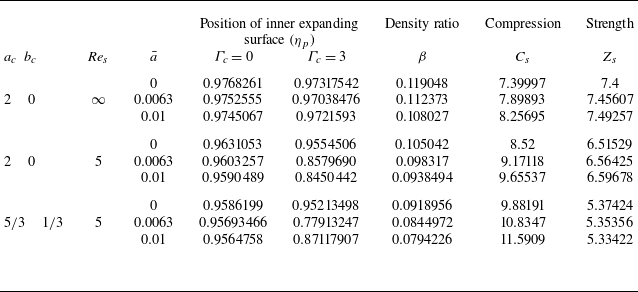


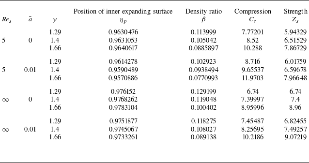


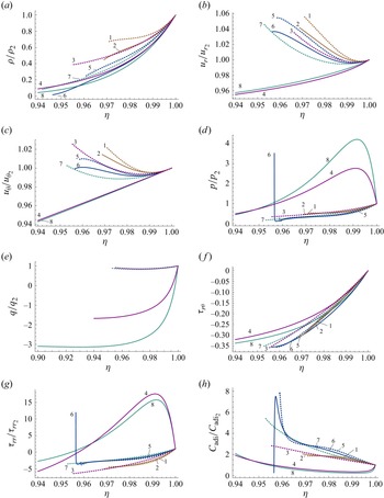


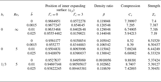


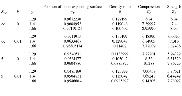


 Open access

