


1. Introduction
Fossil fuels currently account for around 80 % of the global energy supply (Energy Institute, 2024). Due to climate change, the use of fossil fuels must be significantly reduced, with green hydrogen playing an important role in the decarbonization of energy-intensive industries (Reference Sarker, Azad, Rasul and DoppalapudiSarker et al., 2023). The storage of hydrogen is a major challenge due to its low density (Reference Hassan, Ramadan, Saleh and HisselHassan et al., 2021). Due to its high hydrogen storage density and easy liquefaction, ammonia is a promising chemical hydrogen storage medium (Reference Lucentini, Garcia, Vendrell and LlorcaLucentini et al., 2021). The ammonia decomposition for hydrogen generation takes place in catalytic reactors according to Equation (1):

Two types of catalytic reactors for ammonia decomposition are widely used: packed-bed reactors, where the core structure is filled with catalyst material (Reference Cherif, Zarei, Lee, Yoon and LeeCherif et al., 2024; Reference Nailwal, Chotalia, Salvi, Goswami, Muhmood, Adak and KarNailwal et al., 2023; Reference Seyfeli and VarisliSeyfeli & Varisli, 2022), and microchannel reactors, where the channel walls of the core structure are coated with catalyst material (Reference Engelbrecht, Chiuta and BessarabovEngelbrecht et al., 2018; Reference Weissenberger, Zapf, Pennemann and KolbWeissenberger et al., 2024). The specific surface area is a major factor influencing the conversion rate in the ammonia decomposition reactor, since the reaction takes place on the surface of the catalyst (Reference Borisov, Iost, Temerev, Leont’eva, Muromtsev, Arbuzov, Trenikhin, Savel’eva, Smirnova and ShlyapinBorisov et al., 2018). Therefore, porous catalysts with large specific surface areas of up to 156 m2/g are used (Reference Weissenberger, Zapf, Pennemann and KolbWeissenberger et al., 2024). The specific surface area of the core structure can be increased in particular by the number and geometry of the microchannels in reactors (Reference Blauth, Damay, Osterroth, Leithäuser, Hofmann, Kolb, Wichert, Steiner and BortzBlauth et al., 2024; Reference Chiuta, Everson, Neomagus, Le Grange and BessarabovChiuta et al., 2014; Reference Engelbrecht, Chiuta and BessarabovEngelbrecht et al., 2018; Reference Ganley, Seebauer and MaselGanley et al., 2004; Reference Weissenberger, Zapf, Pennemann and KolbWeissenberger et al., 2024).
Energy in the form of heat must be supplied to the endothermic reaction. Since reaction (1) is highly temperature-dependent, even small increases in temperature can achieve a significant increase in the ammonia conversion rate (Reference Nailwal, Chotalia, Salvi, Goswami, Muhmood, Adak and KarNailwal et al., 2023). However, especially in reactors with a large specific surface area the endothermic reaction can lead to cold spots, which have a negative impact on the ammonia conversion rate (Reference Gómez-Cápiro, Ristig, Folke and RulandGómez-Cápiro et al., 2024). Reference Cherif, Zarei, Lee, Yoon and LeeCherif et al. (2024) simulated an inhomogeneous temperature distribution between 901–984.72 K at the outlet of an electrically heated reactor. Reference Seyfeli and VarisliSeyfeli and Varisli (2022) measured a similar temperature difference of 60–70 K with a pyrometer in a packed-bed reactor. Many publications on electrically heated microchannel reactors only consider a single layer of microchannels, which offers the advantage of a homogeneous temperature distribution (Reference Chiuta, Everson, Neomagus, Le Grange and BessarabovChiuta et al., 2014; Reference Ganley, Seebauer and MaselGanley et al., 2004; Reference Weissenberger, Zapf, Pennemann and KolbWeissenberger et al., 2024). However, this severely limits geometric freedom and the possibility of upscaling, since it is not possible to build up the core structure in one spatial direction without losing the homogeneous temperature distribution.
Additive manufacturing offers new possibilities for the design of complex components (Reference Lachmayer, Ehlers and LippertLachmayer et al., 2024), with a great deal of research interest currently focusing on multi-material additive manufacturing (MMAM) (Reference Schneck, Horn, Schmitt, Seidel, Schlick and ReinhartSchneck et al., 2021). MMAM is also expected to become increasingly relevant in the manufacturing of hydrogen energy components (Reference Mesecke, Meyer, Oel and LachmayerMesecke et al., 2025). The processing of multiple materials in a single component adds another degree of freedom to the design process, which means that the local properties of the component can be influenced by the material (Reference Oel, Rossmann, Bode, Meyer, Ehlers, Hackl and LachmayerOel et al., 2023). To date, MMAM has not yet been demonstrated for the manufacturing of catalytic reactors (Reference Mesecke, Meyer, Brechelt, Zerner, Galati, Prabha, Schröder, Wesling, Kaierle, Ahlers and LachmayerMesecke et al., 2026). However, there are examples in the literature of its use in heat exchangers (Reference Li and SeibelLi & Seibel, 2023; Reference Li, Pan, Smolej, Karthik Nadimpalli and MoshiriLi et al., 2024), with the demonstrators mostly serving as proofs of manufacturing feasibility with a technology maturity level of approximately 4-5 (Reference Schneck, Horn, Schmitt, Seidel, Schlick and ReinhartSchneck et al., 2021). This maturity regarding catalytic reactors has already been demonstrated for mono-material additive manufacturing by Reference Wei, Li, Liu, He, Wang, Tan, Wang, Peng, Yang and TsubakiWei et al. (2020) through the production of various self-catalytic reactors for Fischer-Tropsch synthesis, CO2 hydrogenation and methane reforming.
The approach in this study is that MMAM can be used to process two materials that enable a more homogeneous temperature distribution in microchannel reactors with a high specific surface area. This specifically refers to a corrosion-resistant material (e.g., stainless steel 316L) for the direct contact with the reactants and a material with a high thermal conductivity (e.g., copper alloy CuCr1Zr) for the temperature distribution inside the reactor. MMAM allows for a degree of freedom in material distribution that cannot be achieved with conventional methods, thus enabling this study. To investigate this approach, this paper examines the influence of different MMAM designs of ammonia decomposition reactors on the specific surface area of the core structure and temperature distribution. It analyzes the trade-off between maximizing the specific surface area of the core structure and temperature distribution using CFD simulations. MMAM designs made of stainless steel 316L and the copper alloy CuCr1Zr, which are suitable for additive manufacturing using the powder bed fusion of metals using a laser beam (PBF-LB/M) process (Reference Meyer, Oel, Ehlers and LachmayerMeyer et al., 2023a), are considered. A comparison is also made between the MMAM designs and the same designs in mono-material stainless steel in order to quantify the effect of using MMAM.
This study serves as a preliminary work for a future multi-objective optimization to find the optimal MMAM design for ammonia decomposition reactors.
2. Materials and methods
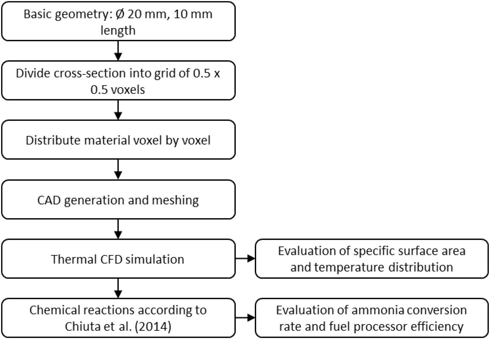
The methodological approach used in this study is illustrated in Figure 1 and explained in the following chapters.
Complete workflow for the simulations in this study

2.1. CAD-models
The CAD designs for the simulations consist of tubular microchannel reactors with a diameter of 20 mm and a length of 10 mm (Figure 2). The cross-sectional area of the reactor is varied in the designs and then extruded over a length of 10 mm. For the design of the cross-sectional area, the circle with a diameter of 20 mm is divided into 0.5 x 0.5 mm squares, because this is the voxel resolution for material deposition in the multi-material PBF-LB/M system (Aconity MIDI+ equipped with an Aerosint Selective Powder Deposition Recoater V1.0). A video describing the material deposition in this system is available from Reference Meyer, Messmann, Oel, Ehlers and LachmayerMeyer et al. (2023b).
Tubular multi-material microchannel design for ammonia decomposition; the design is tailored to multi-material additive manufacturing using the PBF-LB/M process

The following rules were applied for the material distribution in the cross-section:
-
• Fluid channels consist of 1 x 1 mm (2 x 2 voxels). The specific surface area can be increased by adding channels.
-
• At least one layer (wall thickness of 0.5 mm) of stainless steel 316L must be placed around each fluid channel. This is necessary to prevent corrosion due to contact of CuCr1Zr with ammonia or hydrogen embrittlement due to contact with hydrogen.
-
• The remaining voxels in the design are filled with CuCr1Zr for multi-material reactors or with 316L for mono-material reactors.
Following this procedure, 12 different designs were created, resulting in 24 CAD models using the multi-material and mono-material approach. The number of channels varies between 61 and 101 channels, which results in a variation in the specific surface area
 from 776.68 m²/m3 to 1413.30 m²/m³. In addition to the number of channels, the position of the channels and the material distribution between the channels also vary (see Figure 3). All CAD models are published online as research data in the neutral STEP file format (Reference Mesecke and LachmayerMesecke & Lachmayer, 2025). The 12 MMAM designs for the ammonia decomposition reactors are shown in Figure 3.
Overview of the 12 MMAM designs; the sorting is done according to the increasing specific surface area SV from top left to bottom right

Figure 3 Long description
Panel A: A circular design with a nested square pattern, labeled Design A with a specific surface area of 776.68 square meters per cubic meter. Panel B: A circular design with horizontal rows of square blocks, labeled Design B with a specific surface area of 904.00 square meters per cubic meter. Panel C: A circular design with a grid-like pattern of square blocks, labeled Design C with a specific surface area of 942.20 square meters per cubic meter. Panel D: A circular design with a maze-like pattern of square blocks, labeled Design D with a specific surface area of 967.66 square meters per cubic meter. Panel E: A circular design with a half-filled grid pattern, labeled Design E with a specific surface area of 1044.06 square meters per cubic meter. Panel F: A circular design with a complex maze-like pattern, labeled Design F with a specific surface area of 1120.45 square meters per cubic meter. Panel G: A circular design with a cross-like pattern of square blocks, labeled Design G with a specific surface area of 1133.18 square meters per cubic meter. Panel H: A circular design with a complex maze-like pattern, labeled Design H with a specific surface area of 1158.65 square meters per cubic meter. Panel I: A circular design with a complex maze-like pattern, labeled Design I with a specific surface area of 1196.85 square meters per cubic meter. Panel J: A circular design with a grid-like pattern of square blocks, labeled Design J with a specific surface area of 1285.97 square meters per cubic meter. Panel K: A circular design with a grid-like pattern of square blocks, labeled Design K with a specific surface area of 1285.97 square meters per cubic meter. Panel L: A circular design with a dense grid-like pattern of square blocks, labeled Design L with a specific surface area of 1413.30 square meters per cubic meter.
2.2. Meshing
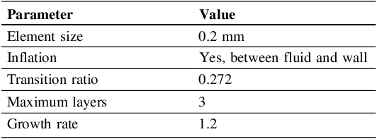
Meshing was performed in Ansys Meshing. The element size for the mesh was set to 0.2 mm. Prism layers were added at the transition between the fluid and the wall to improve the resolution of heat transfer in the CFD simulations. With this meshing, the CAD designs have a node count of approximately 900,000. One CFD simulation was repeated with a mesh resolution of 0.1 mm, which means a node count that is approximately eight times larger. Since this simulation did not reveal any significant deviations from the selected mesh, it is assumed that the selected mesh is sufficiently fine. The meshing parameters are summarized in Table 1.
Overview of meshing parameters

2.3. CFD simulation
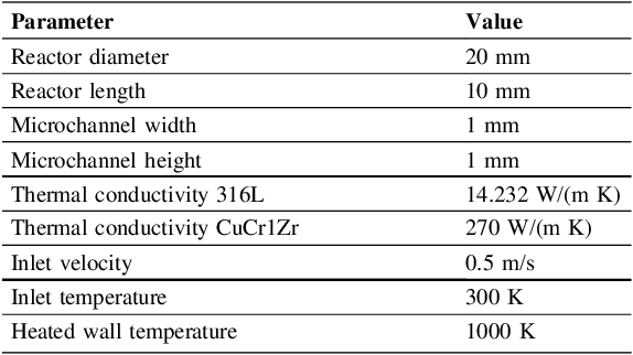
The CFD simulations are performed using Ansys Fluent 2025 R2. First, the materials are specified. The material properties of ammonia and stainless steel 316L are taken from the databases contained in Ansys Fluent. CuCr1Zr is not included in these databases and is created manually. The thermal conductivity of CuCr1Zr is specified as 270 W/(m K) for MMAM components after heat treatment, according to the measurements by Reference Meyer, Messmann, Ehlers and LachmayerMeyer et al. (2025). A constant temperature of 1000 K is used for the electrically heated wall of the reactor. A velocity of 0.5 m/s and a temperature of 300 K are defined for the inlets of the fluid channels. The simulation conditions are summarized in Table 2. Additional simplifying assumptions for the CFD simulations are:
-
• Adiabatic steady state conditions
-
• gauge pressure of 0 Pa at the outlet
-
• no-slip on the walls
-
• incompressible laminar flow
-
• standard convergence criteria from Ansys Fluent 2025 R2.
One CFD simulation was repeated with convergence criteria reduced by a factor of 10. Since this simulation did not reveal any significant deviations from the standard convergence criteria, it is assumed that the standard convergence criteria are sufficient.
Overview of simulation conditions

2.4. Calculation of fuel processor efficiency
The CFD simulations only simulate heat transfer and no chemical reactions. Separating thermal and chemical simulations to reduce the numerical effort is a common practice (Reference Blauth, Damay, Osterroth, Leithäuser, Hofmann, Kolb, Wichert, Steiner and BortzBlauth et al., 2024). The results of the thermal simulations can then be used to determine the conversion of ammonia based on the kinetic data from the chemical reactions. In this paper, the kinetic data from Reference Chiuta, Everson, Neomagus, Le Grange and BessarabovChiuta et al. (2014) is used to determine the ammonia decomposition rate. The simplifying assumption is made that the microchannels behave in the same way in terms of chemical kinetics in this study as in the article by Reference Chiuta, Everson, Neomagus, Le Grange and BessarabovChiuta et al. (2014). This allows the ammonia conversion to be specified for each channel based on the temperature determined in the CFD simulations.
The efficiency of the ammonia decomposition reactor designs examined in this study is compared using the fuel processor efficiency according to Reference Blauth, Damay, Osterroth, Leithäuser, Hofmann, Kolb, Wichert, Steiner and BortzBlauth et al. (2024). The fuel processor efficiency is the ratio of the power contained in the hydrogen produced by the reactor to the power contained in the ammonia used in the process. Since the reaction enthalpy for ammonia decomposition has not yet been considered in the thermal simulations, it is added to the calculation. This results in the following Equation (2):

where
 and
and
 are the molar flow rates of hydrogen and ammonia respectively,
 are the lower heating values of each gas,
 is the reaction enthalpy and
 are the external heat inputs.
3. Results
The influence of the design on the temperature distribution in the reactor is investigated using the thermal CFD simulations. For the various designs, temperature gradients in the gas at the outlet of up to 68.35 K are observed (see Figure 4). In most cases, a larger temperature gradient is observed in the mono-material reactors. The corresponding MMAM design can reduce the temperature gradient by up to 26.81 K. Plotting the Pareto front in Figure 4 a) shows that the MMAM designs primarily offer the best compromise between a high specific surface area and a low temperature gradient. The ideal point is also plotted and would mean a reactor with a large specific surface area and a low temperature gradient in the gas at the outlets. Figure 4 b) shows the simulated temperature distribution in the cross-section of the reactor (Design G) at the length of 5 mm. Compared to the mono-material design (top), the MMAM design (bottom) shows a significantly more homogeneous temperature distribution.
a) Temperature gradient in the gas at the outlets of the microchannels for the 24 simulated designs; b) Simulation results of the cross-section through the reactor (Design G) at the length of 5 mm for a mono-material design and the corresponding MMAM design

Figure 4 Long description
Panel A: A scatter plot shows the temperature gradient in Kelvin on the vertical axis and the specific surface area in square meters per cubic meter on the horizontal axis. The plot includes data points for mono-material 316L and multi-material 316L-CuCr1Zr designs, with a dashed line indicating the Pareto-Front and a star marking the ideal point. Panel B: Two circular heat maps display temperature distributions in Kelvin for mono-material design and multi-material design at a reactor length of 5 millimeters. The color scale ranges from blue at 930 Kelvin to red at 1000 Kelvin.
Figure 5 shows the estimated fuel processor efficiency of the 24 simulated designs, calculated using the procedure described in Section 2.4. It is visible that switching from mono-material design to the corresponding MMAM design (same specific surface area) increases the fuel processor efficiency. Depending on the design, this effect ranges between 0.4 %pt. and 3.2 %pt.
Fuel processor efficiency calculated using Equation (2) for the 24 simulated designs

The ammonia conversion derived from the thermal CFD simulations ranges between 89.16 %pt. and 99.59 %pt. for the 24 designs considered in this study. Switching from the mono-material design to the corresponding MMAM design increases the calculated ammonia conversion by up to 4.17 %pt. Table 3 summarizes the effects of switching from mono-material design to the corresponding MMAM design. The smallest effect of the range is on the left and the largest effect is on the right.
The complete simulation results are published as research data in neutral CSV file format (Reference Mesecke and LachmayerMesecke & Lachmayer, 2025). This also includes all performance parameters for all MMAM and mono-material designs.
Effects of switching from mono-material designs to MMAM designs; the range for the 12 simulated design pairs (mono-material design and the corresponding MMAM design) is given

4. Discussion
The results of this study show a temperature gradient of up to 68.35 K for the microchannel reactors investigated. This value fits well with the literature values of 60 K to 83.72 K (Reference Cherif, Zarei, Lee, Yoon and LeeCherif et al., 2024, Reference Seyfeli and VarisliSeyfeli & Varisli, 2022) mentioned in Section 1. In most cases, the corresponding MMAM design reduces the temperature gradient, which can be explained by the improved thermal conductivity of CuCr1Zr. This effect depends strongly on the design. For Design I (
 = 1196.85 m²/m³), the temperature gradient actually increases due to the change from the mono-material design to the MMAM design. This is because this design improves the temperature conduction to some microchannels more than to others, causing the temperature gradient to increase. The average gas temperature for this design increases by 5.15 K due to the change from the mono-material design to the MMAM design. This means that, on average, the MMAM design also offers an improved heat transfer in this case.
In general, the model assumptions must be taken into account when evaluating the results. The thermal simulations were performed only with
 without chemical reactions. In the real reactor, however, the gas composition changes with the chemical reactions over the length of the reactor. Due to the varying number of molecules and different thermal properties of the gases
 ,
,
 , and
, and
 , this would also have an impact on the thermal CFD simulations. In this study, the
 conversion was predicted from the thermal simulations and available kinetic data according to Reference Chiuta, Everson, Neomagus, Le Grange and BessarabovChiuta et al. (2014). The fuel processor efficiency is calculated from the
 conversion using equation (2). In this equation, the total energy supplied (
 and
and
 ) is used for heating the gas and the chemical reactions. Due to conversion losses of electrical energy into heat energy and heat losses, the actual fuel processor efficiency will be lower than calculated in this study. It is to be expected that the achievable fuel processor efficiency will be in the range of approx. 75 %, as stated by Reference Blauth, Damay, Osterroth, Leithäuser, Hofmann, Kolb, Wichert, Steiner and BortzBlauth et al. (2024) for electrically heated reactors. Nevertheless, the results in Figure 5 show that the MMAM designs can be expected to improve fuel processor efficiency by up to 3.2 %pt. compared to the corresponding mono-material design. This can be explained primarily by the lower temperature gradient due to improved temperature distribution in the reactor. The resulting increase in ammonia conversion increases fuel processor efficiency while maintaining almost the same energy input.
In this study, the inlet velocity and heated wall temperature were kept constant. It can be assumed that adjusting these operating parameters could slightly optimize fuel processor efficiency for the various designs.
In the CFD simulations in this study, CAD models with smooth walls were assumed, whereas components manufactured by additive manufacturing have a significant surface roughness in their as-built state. Although rough surfaces have a positive effect on heat transfer, they also cause higher pressure losses (Reference Kadivar, Tormey and McGranaghanKadivar et al., 2024). The as-built surface roughness of additive manufacturing must be taken into account as an influencing factor in future work and could even be specifically influenced via the build orientation or printing parameters. In addition, surface roughness can also influence the adhesion of a coating with a catalyst material, whereby it can be assumed that greater roughness enables a better adhesion.
The MMAM designs were explicitly designed for AM. However, qualification challenges in particular must be taken into account for manufacturing and future industrialization. Pores or cracks could lead to leaks, which would pose a safety risk when handling ammonia and hydrogen gases. The maturity of mono-material additive manufacturing for the production of catalytic reactors has already been demonstrated (Reference Wei, Li, Liu, He, Wang, Tan, Wang, Peng, Yang and TsubakiWei et al., 2020). For MMAM, this maturity still needs to be shown in future work. This paper provides possible designs for such tests and thus serves as motivation on the path to MMAM reactors for ammonia decomposition. MMAM for the material combination stainless steel 316L and copper alloy CuCr1Zr in general has already been demonstrated, and detailed investigations of the process parameters have been carried out (Reference Meyer, Oel, Ehlers and LachmayerMeyer et al., 2023a) so that these can be adopted for the MMAM of the ammonia decomposition reactors.
5. Conclusion and outlook
5.1. Conclusion
In this study, the specific surface area and thermal management of microchannel reactors for ammonia decomposition were investigated using CFD simulations. The designs for the core structure of the reactor were designed for MMAM in the PBF-LB/M process. The comparison between the mono-material designs and the corresponding MMAM designs shows the potential for optimizing the core structure using MMAM. The temperature gradient in the gas at the outlet can be reduced, while the average temperature of the gas can be increased. In the calculations made for the chemical reactions, this leads to increased ammonia conversion rates and slightly improved fuel processor efficiencies for the MMAM designs.
The key findings of this study are:
-
• By using MMAM designs, the temperature gradient in the gas at the outlet could be reduced by up to 26.81 K.
-
• The fuel processor efficiency was increased by up to 3.2 %pt. through the use of MMAM designs instead of the corresponding mono-material design.
-
• The achievable effects of using MMAM designs depend on the individual design and vary greatly.
5.2. Outlook
This study shows that significant temperature gradients can occur in microchannel reactors with more than one layer of microchannels, as already known from packed-bed reactors. The results of this study demonstrate the potential for the optimization of the core structure of ammonia decomposition reactors based on thermal and geometric parameters using MMAM. Building on these results, the following points can be addressed in the future:
-
• The operating parameters can be optimized for each design. The inlet velocity and heated wall temperature can be varied to determine the ideal operating point for the design. The simulation environment described in this study can be used for this purpose.
-
• Practical experiments must be carried out to validate the simulation results and demonstrate the maturity of MMAM for the production of ammonia decomposition reactors. The CAD designs provided as research data are suitable for MMAM and enable these investigations.
-
• The designs examined in this study can be used as a starting population for a multi-objective optimization to find the ideal material distribution in the reactor. In order to obtain a sufficiently large starting population, additional designs should be created.
-
• There is a need to automate the geometry generation and the simulation so that an automatic multi-objective optimization can be performed. Automation should incorporate the design rules established in this study to ensure manufacturability with MMAM.
-
• In addition to optimizing the cross-sectional area of the microchannel reactor, it could also be optimized lengthwise in the future. This would allow the variable gas composition due to chemical reactions or heat transfer through complex channel paths to be taken into account.
Nomenclature
-

-
Hydrogen
-
-
Lower heating value of hydrogen
-
-
Lower heating value of ammonia
-
-
Reaction enthalpy
- MMAM
-
Multi-material additive manufacturing
-
-
Nitrogen
-
-
Ammonia
-
-
Fuel processor efficiency
-
-
Molar flow rate of hydrogen
-
-
Molar flow rate of ammonia
- PBF-LB/M
-
powder bed fusion of metals using a laser beam
-
-
External heat inputs
-
-
Specific surface area
-
-
Temperature gradient in the gas at the outlets


Acknowledgement
This work is part of the project “Additive Fertigung multimaterieller Komponenten zur nachhaltigen Energiewandlung”, which was funded by the European Regional Development Fund (ERDF) and the state of Lower Saxony – Project number ZW 7–87011865.






 Open access

