


1. Introduction
Violent droplet impacts onto rough or textured substrates have extensive applications across nature and engineering, as well as being of fundamental scientific interest. Herein, a droplet impact is considered to be violent if the impact results in splash jets and ejecta, rather than gradual spreading over the surface. We also assume that the effect of air cushioning on the impact is negligible. The presence of surface roughness can critically change behaviour after impact compared with the corona splashing or droplet spreading that are associated with droplet impacts upon a smooth surface. Roughness height has been shown to be important in determining whether a droplet impact will result in spreading or a splash (García-Geijo et al. Reference García-Geijo, Quintero, Riboux and Gordillo2021) and roughness can also trigger prompt splashing (Josserand et al. Reference Josserand, Lemoyne, Troeger and Zaleski2005; Xu Reference Xu2007; Quetzeri-Santiago, Castrejón-Pita & Castrejón-Pita Reference Quetzeri-Santiago, Castrejón-Pita and Castrejón-Pita2019). Further practical interest is driven by the behaviour of droplets impacting upon superhydrophobic surfaces. Inspired by the repellent properties of lotus leaves (Gilet & Bourouiba Reference Gilet and Bourouiba2014; Gart et al. Reference Gart, Mates, Megaridis and Jung2015; Roth-Nebelsick et al. Reference Roth-Nebelsick, Konrad, Ebner, Miranda, Thielen, Nebelsick and Bauer2022), surfaces have been engineered with periodic arrays of micro pillars (Maitra et al. Reference Maitra, Antonini, Tiwari, Mularczyk, Imeri, Schoch and Poulikakos2014b ; van der Veen et al. Reference van der Veen, Hendrix, Tran, Sun, Tsai and Lohse2014) and understanding how these superhydrophobic properties persist during high-speed droplet impacts (rather than low- or moderate-speed impacts that are much studied) is of critical importance to the use of such surfaces in many applications, including preventing in-flight ice formation on aircraft. Beyond repelling droplets, textured surfaces with heterogeneous roughness (Yang et al. Reference Yang, Wu, Chen, Huang, Wu, Falkman and Sundén2020) and arrays of micro pillars (Broom & Willmott 2022, Reference Broom and Willmott2023) have been shown to break the axisymmetry associated with the initial stages of a droplet impact by inducing preferential flow directions, which may open possibilities for using roughness to further control droplet impact behaviour.
A widely used modelling approach for droplet impacts onto a substrate, as well as for water entry problems, is known as Wagner theory (Wagner Reference Wagner1932; Korobkin Reference Korobkin1997; Oliver Reference Oliver2002; Moore Reference Moore2014). This has been extended in many directions to include more complex substrate behaviour including elasticity (Pegg, Purvis & Korobkin Reference Pegg, Purvis and Korobkin2018; Khabakhpasheva & Korobkin Reference Khabakhpasheva and Korobkin2020), porosity (Moreton, Purvis & Cooker Reference Moreton, Purvis and Cooker2024), oblique impacts (Moore et al. Reference Moore, Howison, Ockendon and Oliver2013a ) and, of most relevance to the current work, roughness. This includes Ellis, Smith & White (Reference Ellis, Smith and White2011), who provided a detailed analysis of the spreading of an impacting droplet encountering isolated roughness after impact as well as looking at a liquid sheet impacting onto a periodic rough surface, and Hicks (Reference Hicks2022), who examined droplets impacting a range of arbitrary rough substrates, including spreading over a small number of repeated roughness elements. In the context of water entry problems in marine hydrodynamics, Korobkin (Reference Korobkin1996) studied the effect of superimposing small amplitude periodic cosine roughness on a parabolic impactor. In addition to experimental and modelling work, high-fidelity simulations have started to investigate droplet impacts with roughness (Quan & Zhang Reference Quan and Zhang2014; Tan Reference Tan2017; Henman, Smith & Tiwari Reference Henman, Smith and Tiwari2023), while related problems such as a droplet impact with a mesh screen has also been studied (Liwei et al. Reference Liwei, Xiao, Weijie, Pengfei, Feng and Xiwen2019). However, resolving flow between roughness elements makes these simulations significantly more challenging than those for a droplet impact with a flat substrate.
The current study builds on the work of Hicks (Reference Hicks2022) to develop the Wagner solution for droplet impacts onto surfaces with periodic roughness. Herein, novelty stems from describing the substrate shape with a Fourier series, and while the earlier work of Hicks (Reference Hicks2022) is restricted in only being able to investigate droplet impacts with a small number of roughness elements, using a Fourier series to represent the substrate shape facilitates the investigation of the longer term impact behaviour as a droplet encounters a periodic array of roughness elements. Results are presented for a range of substrates, particularly in cases where the impact is additionally symmetric, while the loads due to a droplet impact with a rough surface are compared with loads in impacts with a flat surface. In § 2, the salient points of Wagner theory as it applies to droplet impacts with rough substrates are introduced, while in § 3, the simplifications that can be made to the theory when the periodic rough surface is represented by a Fourier series are described and are shown to yield an explicit solution for the contact line spreading position in terms of Bessel functions. The large time contact line evolution for impacts with periodic roughness modelled using Fourier series is also obtained. Section 4 begins by explaining how the theory can be further simplified by assuming an impact with a substrate with even periodic roughness, before going on to investigate a range of different roughness shapes, focussing on how the height and spatial period of the roughness affect the resulting impact. Relationships between the roughness height and spatial period for the boundary of the regime where a contiguous impact site is expected are developed. Further discussion and conclusions are given in § 5, which also places our findings in the context of existing experimental results.
2. Droplet impacts with a rough substrate
The early stages of a droplet impact with a rough surface are investigated assuming the intervening air layer initially located between the droplet and substrate has a negligible influence on the impact dynamics. A frame of reference is used in which an idealised two-dimensional droplet of radius $R$
is initially stationary and a surface of shape
$R$
is initially stationary and a surface of shape $\tilde {S} ( \tilde {x} )$
ascends towards the droplet with speed
$\tilde {S} ( \tilde {x} )$
ascends towards the droplet with speed $U$
(as shown in figure 1
a). The problem is formulated in this frame of reference so that in the droplet, there is zero motion in the far-field. To facilitate the comparison of different substrate shapes, it is assumed that the highest points of the roughness are at
$U$
(as shown in figure 1
a). The problem is formulated in this frame of reference so that in the droplet, there is zero motion in the far-field. To facilitate the comparison of different substrate shapes, it is assumed that the highest points of the roughness are at $\tilde {y} = 0$
, i.e.
$\tilde {y} = 0$
, i.e. $\max ( \tilde {S} ( \tilde {x} ) ) = 0$
, while a time origin is chosen so that the substrate first impacts the droplet surface when
$\max ( \tilde {S} ( \tilde {x} ) ) = 0$
, while a time origin is chosen so that the substrate first impacts the droplet surface when $\tilde {t}=0$
. It is not initially presumed that
$\tilde {t}=0$
. It is not initially presumed that $\tilde {S} ( 0 ) = 0$
, so the bottom of the droplet may need to be located a vertical distance
$\tilde {S} ( 0 ) = 0$
, so the bottom of the droplet may need to be located a vertical distance $\tilde {h}_0$
below the maximum height of the surface roughness to facilitate initial touchdown when
$\tilde {h}_0$
below the maximum height of the surface roughness to facilitate initial touchdown when $\tilde {t} = 0$
, with the initial point of touchdown being denoted
$\tilde {t} = 0$
, with the initial point of touchdown being denoted $(\tilde {x}_0,\tilde {y}_0)$
. Given symmetry of the surface is also not initially assumed, there is no requirement for the initial touchdown to occur on
$(\tilde {x}_0,\tilde {y}_0)$
. Given symmetry of the surface is also not initially assumed, there is no requirement for the initial touchdown to occur on $\tilde {x}_0 = 0$
. Here, dimensional variables are shown with a tilde, while subsequently, the corresponding non-dimensional variables are shown without tildes.
$\tilde {x}_0 = 0$
. Here, dimensional variables are shown with a tilde, while subsequently, the corresponding non-dimensional variables are shown without tildes.
(a) Droplet impact with a rough substrate in dimensional variables in a frame of reference where the droplet appears stationary in the far field and the substrate ascends towards the droplet. (b) Non-dimensional local solution close to the initial impact point $(x_0,\,y_0)$
at
$(x_0,\,y_0)$
at $t = 0$
(top) and the corresponding mixed boundary value problem for
$t = 0$
(top) and the corresponding mixed boundary value problem for $t \gt 0$
(bottom). The boundary condition on
$t \gt 0$
(bottom). The boundary condition on $\unicode {x2460}$
is given by (2.2b
), while the boundary conditions on
$\unicode {x2460}$
is given by (2.2b
), while the boundary conditions on $\unicode {x2461}$
are given by (2.2c
) and (2.3). (c) Non-dimensional local solution close to the initial impact point in the special case where the substrate geometry is an even function with
$\unicode {x2461}$
are given by (2.2c
) and (2.3). (c) Non-dimensional local solution close to the initial impact point in the special case where the substrate geometry is an even function with $S(0) = 0$
. The boundary conditions in the primed regions match their unprimed counterparts with
$S(0) = 0$
. The boundary conditions in the primed regions match their unprimed counterparts with $a(t) = -b(t)$
and
$a(t) = -b(t)$
and $h_0 = 0$
.
$h_0 = 0$
.

A small parameter $\varepsilon$
, based on the ratio of the characteristic height of the surface roughness to the spatial period over which the pattern of the surface roughness repeats, is used to focus on the region close to the initial impact site at the bottom of the droplet. Fluid velocities are non-dimensionalised using
$\varepsilon$
, based on the ratio of the characteristic height of the surface roughness to the spatial period over which the pattern of the surface roughness repeats, is used to focus on the region close to the initial impact site at the bottom of the droplet. Fluid velocities are non-dimensionalised using $U$
, while in the local region close to the impact site, both the droplet and the horizontal extent of the surface roughness have a length scale of
$U$
, while in the local region close to the impact site, both the droplet and the horizontal extent of the surface roughness have a length scale of $\varepsilon R$
. Given the definition of
$\varepsilon R$
. Given the definition of $\varepsilon$
, the vertical height of the roughness is scaled by
$\varepsilon$
, the vertical height of the roughness is scaled by $\varepsilon ^2 R$
, while the same scaling is also applied to the vertical position of the droplet free surface. The relevant time scale is that corresponding to the time taken for the substrate to move a distance comparable to the height of the roughness, i.e.
$\varepsilon ^2 R$
, while the same scaling is also applied to the vertical position of the droplet free surface. The relevant time scale is that corresponding to the time taken for the substrate to move a distance comparable to the height of the roughness, i.e. $\varepsilon ^2 R/U$
, while to retain the liquid pressure to leading order, the characteristic pressure scale is taken to be
$\varepsilon ^2 R/U$
, while to retain the liquid pressure to leading order, the characteristic pressure scale is taken to be $\rho U^2/\varepsilon$
, where
$\rho U^2/\varepsilon$
, where $\rho$
is the liquid density. This choice of non-dimensionalisation gives a characteristic scale for the load on the surface of
$\rho$
is the liquid density. This choice of non-dimensionalisation gives a characteristic scale for the load on the surface of $\rho U^2 R$
. For a water droplet of radius
$\rho U^2 R$
. For a water droplet of radius $1$
mm with an impact velocity of
$1$
mm with an impact velocity of $2$
m s−1, the Reynolds number for the droplet
$2$
m s−1, the Reynolds number for the droplet $\rho U R/\unicode{x03BC} = 1993$
, the Weber number
$\rho U R/\unicode{x03BC} = 1993$
, the Weber number $\rho U^2 R/\sigma = 55$
, the Froude number
$\rho U^2 R/\sigma = 55$
, the Froude number $U/\sqrt {g R} = 20$
and the Mach number for the droplet
$U/\sqrt {g R} = 20$
and the Mach number for the droplet $U/c = 0.0058$
, and hence for this and other high-speed droplet impacts, the effects of viscosity, surface tension, gravity and compressibility in the droplet can be neglected. Here,
$U/c = 0.0058$
, and hence for this and other high-speed droplet impacts, the effects of viscosity, surface tension, gravity and compressibility in the droplet can be neglected. Here, $\unicode{x03BC}$
denotes the dynamic viscosity of the water,
$\unicode{x03BC}$
denotes the dynamic viscosity of the water, $\sigma$
is the surface tension coefficient between water and air,
$\sigma$
is the surface tension coefficient between water and air, $g$
is the acceleration due to gravity, and
$g$
is the acceleration due to gravity, and $c$
is the speed of sound in the liquid. Consequently, with this non-dimensionalisation, the leading order problem in
$c$
is the speed of sound in the liquid. Consequently, with this non-dimensionalisation, the leading order problem in $\varepsilon$
reduces to a mixed boundary value problem in the upper half-plane, with differing boundary conditions where the droplet and substrate are, and are not in contact. The extent of the wetted surface at each instant is unknown and must be determined. This mixed boundary value problem is commonly referred to as the outer problem in Wagner theory and it is this that forms the focus of the current study. Within this outer problem, the free surface is required to meet the substrate at the extremes of the wetted contact patch in what is known as the Wagner condition. However, at the extremes of this wetted contact patch, the pressure on the substrate is locally unbounded and this is resolved asymptotically by considering a local inner region close to this point in which there is a turnover of the free surface with liquid being ejected away from the contact line via a splash jet (Howison, Ockendon & Wilson Reference Howison, Ockendon and Wilson1991; Oliver Reference Oliver2002). Given our focus on the outer problem, when secondary impacts are considered, these will be on the scale of the outer problem. However, the splash jets created by the impact may themselves also undergo secondary impacts with the substrate prior to any secondary impacts related to the outer problem. The roughness of the substrate actually increases the likelihood of this happening and indeed is likely responsible for the phenomena of prompt splashing (Xu Reference Xu2007). However, as the fluid mass associated with the splash jet is small compared with the fluid remaining in the droplet, their secondary impacts are not considered.
$\varepsilon$
reduces to a mixed boundary value problem in the upper half-plane, with differing boundary conditions where the droplet and substrate are, and are not in contact. The extent of the wetted surface at each instant is unknown and must be determined. This mixed boundary value problem is commonly referred to as the outer problem in Wagner theory and it is this that forms the focus of the current study. Within this outer problem, the free surface is required to meet the substrate at the extremes of the wetted contact patch in what is known as the Wagner condition. However, at the extremes of this wetted contact patch, the pressure on the substrate is locally unbounded and this is resolved asymptotically by considering a local inner region close to this point in which there is a turnover of the free surface with liquid being ejected away from the contact line via a splash jet (Howison, Ockendon & Wilson Reference Howison, Ockendon and Wilson1991; Oliver Reference Oliver2002). Given our focus on the outer problem, when secondary impacts are considered, these will be on the scale of the outer problem. However, the splash jets created by the impact may themselves also undergo secondary impacts with the substrate prior to any secondary impacts related to the outer problem. The roughness of the substrate actually increases the likelihood of this happening and indeed is likely responsible for the phenomena of prompt splashing (Xu Reference Xu2007). However, as the fluid mass associated with the splash jet is small compared with the fluid remaining in the droplet, their secondary impacts are not considered.
A single contiguous impact over the wetted surface $a(t) \lt x \lt b(t)$
is assumed, with no secondary or multiple impacts occurring. As an analogy with less dynamic wetting of a rough substrate, this is equivalent to Wenzel wetting where all the surfaces of the substrates are coated by liquid, rather than leaving voids of gas between roughness elements (as is observed in Cassie–Baxter wetting). For higher-speed violent impacts considered herein, the assumption that the impact fully wets the surface is justified, as the large inertial pressures in the droplet are expected to overcome the capillary pressures created between the droplet free surface and the substrate roughness.
$a(t) \lt x \lt b(t)$
is assumed, with no secondary or multiple impacts occurring. As an analogy with less dynamic wetting of a rough substrate, this is equivalent to Wenzel wetting where all the surfaces of the substrates are coated by liquid, rather than leaving voids of gas between roughness elements (as is observed in Cassie–Baxter wetting). For higher-speed violent impacts considered herein, the assumption that the impact fully wets the surface is justified, as the large inertial pressures in the droplet are expected to overcome the capillary pressures created between the droplet free surface and the substrate roughness.
The displacement potential $\Phi ( x,\,y,\,t )$
, as defined by Korobkin & Pukhnachov (Reference Korobkin and Pukhnachov1988), is related to the velocity potential
$\Phi ( x,\,y,\,t )$
, as defined by Korobkin & Pukhnachov (Reference Korobkin and Pukhnachov1988), is related to the velocity potential $\phi ( x,\,y,\,t )$
, through
$\phi ( x,\,y,\,t )$
, through
 \begin{align} \Phi \!\left ( x,\,y,\,t \right ) = - \int _0^t \phi \!\left ( x,\,y,\,\hat {t} \right ) \,\mathrm{d}{\hat {t}}. \end{align}
With the non-dimensionalisation described previously, the displacement potential satisfies
 \begin{align} \Phi _{xx} + \Phi _{yy} &= 0 \quad \mbox{for} \quad y \gt 0, \end{align}
to leading order in the droplet. Furthermore, the kinematic boundary condition on the wetted substrate, Bernoulli’s equation and the far-field droplet behaviour imply to leading order
 \begin{align}&\Phi _y = \tfrac {1}{2} x^2 - h_0 - S\!\left ( x \right ) - t \qquad\qquad\mbox{for}\,y = 0\ \mbox{and}\ a(t) \lt x \lt b(t), \end{align}
 \begin{align}&\Phi _x = 0 \qquad\qquad\qquad\qquad\qquad\qquad\kern-1.7pt\mbox{for}\;y = 0\ \mbox{and}\ x \lt a(t)\;\mbox{or}\;x \gt b(t), \end{align}
 \begin{align}&\quad \Phi \rightarrow 0, \qquad\qquad\qquad\qquad\qquad\kern4.2pt\mbox{as}\,\sqrt {x^2 + y^2} \rightarrow \infty , \end{align}
respectively, while the kinematic boundary condition on the droplet free surface implies (Hicks Reference Hicks2022)
 \begin{align} \Phi _y &= \tfrac {1}{2} x^2 - h_0 - h\!\left ( x,\,t \right ) \quad \mbox{for}\;y = 0\;\mbox{and}\;x \lt a(t)\;\mbox{or}\;x \gt b(t). \end{align}
Following Moore et al. (Reference Moore, Ockendon and Oliver2013b
), this mixed boundary value problem (which is summarised in figure 1
b), can be investigated by defining $\Upsilon \equiv \Phi + \mathrm{i} \Psi$
, where
$\Upsilon \equiv \Phi + \mathrm{i} \Psi$
, where $\Psi$
is the harmonic conjugate of the displacement potential
$\Psi$
is the harmonic conjugate of the displacement potential $\Phi$
. As
$\Phi$
. As $\Upsilon$
is holomorphic, the functions
$\Upsilon$
is holomorphic, the functions $\Phi$
and
$\Phi$
and $\Psi$
satisfy the Cauchy–Riemann equations. As
$\Psi$
satisfy the Cauchy–Riemann equations. As $y \searrow 0$
, the characteristic function
$y \searrow 0$
, the characteristic function $\Lambda ( z,\,t ) = \sqrt { (z - b(t) ) (z - a(t) )}$
with
$\Lambda ( z,\,t ) = \sqrt { (z - b(t) ) (z - a(t) )}$
with $z = x + \mathrm{i} y$
, implies
$z = x + \mathrm{i} y$
, implies
 \begin{align} \Lambda \!\left ( x,\,t \right ) = \begin{cases} \sqrt {\left (x - b(t)\right )\left (x - a(t)\right )} & \,\,\mbox{for} \,\,x\gt b(t), \\[3pt] \mathrm{i} \sqrt {\left (b(t) - x\right )\left (x - a(t)\right )} & \,\,\mbox{for} \,\,a(t) \lt x \lt b(t), \\[3pt] -\sqrt {\left (x - b(t)\right )\left (x - a(t)\right )} & \,\,\mbox{for} \,\,x \lt a(t). \end{cases} \end{align}
Consequently, applying Cauchy’s integral formula to $\Upsilon _x ( z,\,t ) / \Lambda ( z,\,t )$
, with an anti-clockwise semi-circular contour in the upper half-plane with a return along the
$\Upsilon _x ( z,\,t ) / \Lambda ( z,\,t )$
, with an anti-clockwise semi-circular contour in the upper half-plane with a return along the $x$
-axis implies
$x$
-axis implies
 \begin{align} \Phi _x\!\left ( x,\,y,\,t \right ) - \mathrm{i} \Phi _y\!\left ( x,\,y,\,t \right ) = \frac {\Lambda \!\left ( z,\,t \right )}{2 \pi \mathrm{i}} \int _{-\infty }^\infty \frac {\left [\Phi _{x}\!\left ( \xi ,\,0,\,t \right ) - \mathrm{i} \Phi _{y}\!\left ( \xi ,\,0,\,t \right )\right ]\,\mathrm{d}{\xi }}{\Lambda \!\left ( \xi ,\,t \right ) \left (\xi - z\right )}. \end{align}
To ensure the displacement of the droplet free surface is bounded at the contact lines $x = a(t)$
and
$x = a(t)$
and $x = b(t)$
, the associated consistency conditions
$x = b(t)$
, the associated consistency conditions
 \begin{align} \int _{-\infty }^\infty \frac {\left [\Phi _{x}\!\left ( \xi ,\,0,\,t \right ) - \mathrm{i} \Phi _{y}\!\left ( \xi ,\,0,\,t \right )\right ] \xi ^m \,\mathrm{d}{\xi }}{\Lambda \!\left ( \xi ,\,t \right )} = 0 \end{align}
for $m=0$
and
$m=0$
and $m=1$
, must also be satisfied. The theoretical underpinning of these equations is explained by Muskhelishvili (Reference Muskhelishvili2008), while this formulation has previously been used to study oblique impacts (Moore et al. Reference Moore, Howison, Ockendon and Oliver2013a
) and asymmetric impacts with individual roughness elements (Hicks Reference Hicks2022). An alternative but equivalent formulation due to Scolan et al. (Reference Scolan, Coche, Coudray and Fontaine1999) gives a more physically intuitive explanation of why these consistency conditions are required. Scolan et al. (Reference Scolan, Coche, Coudray and Fontaine1999) instead applied Cauchy’s integral formula to
$m=1$
, must also be satisfied. The theoretical underpinning of these equations is explained by Muskhelishvili (Reference Muskhelishvili2008), while this formulation has previously been used to study oblique impacts (Moore et al. Reference Moore, Howison, Ockendon and Oliver2013a
) and asymmetric impacts with individual roughness elements (Hicks Reference Hicks2022). An alternative but equivalent formulation due to Scolan et al. (Reference Scolan, Coche, Coudray and Fontaine1999) gives a more physically intuitive explanation of why these consistency conditions are required. Scolan et al. (Reference Scolan, Coche, Coudray and Fontaine1999) instead applied Cauchy’s integral formula to $\Upsilon _x ( z,\,t ) \Lambda ( z,\,t )$
, which results in an integral equation in which the integral is multiplied by
$\Upsilon _x ( z,\,t ) \Lambda ( z,\,t )$
, which results in an integral equation in which the integral is multiplied by $1/\Lambda ( z,\,t )$
. As
$1/\Lambda ( z,\,t )$
. As $1/\Lambda ( z,\,t )$
is unbounded when
$1/\Lambda ( z,\,t )$
is unbounded when $x = a(t)$
or
$x = a(t)$
or $x = b(t)$
, the integral multiplying this singular term is necessarily zero when evaluated at these points. This gives an alternative pair of integral consistency conditions, from which (2.5b
) can be recovered.
$x = b(t)$
, the integral multiplying this singular term is necessarily zero when evaluated at these points. This gives an alternative pair of integral consistency conditions, from which (2.5b
) can be recovered.
To determine the free surface evolution for $x \lt a(t)$
and for
$x \lt a(t)$
and for $x \gt b(t)$
, the integration range is split into the free and wetted portions of the boundary, and the boundary conditions (2.2c
), (2.2b
) and (2.3) are applied to the relevant sections. Upon transforming into a frame of reference in which the droplet descends towards a stationary surface, which is the most convenient frame of reference in which to analyse the results, the imaginary part of (2.5a
) implies
$x \gt b(t)$
, the integration range is split into the free and wetted portions of the boundary, and the boundary conditions (2.2c
), (2.2b
) and (2.3) are applied to the relevant sections. Upon transforming into a frame of reference in which the droplet descends towards a stationary surface, which is the most convenient frame of reference in which to analyse the results, the imaginary part of (2.5a
) implies
 \begin{align} h\!\left ( x,\,t \right ) &= \frac {1}{2} \mbox{sign}\!\left (x - x_0\right ) \left (x + \frac {1}{2} \left (a(t) + b(t)\right )\right ) \sqrt {\left (x - b(t)\right )\left (x - a(t)\right )} \nonumber \\ &\quad - \frac {\mbox{sign}\!\left (x - x_0\right ) \sqrt {\left (x - b(t)\right )\left (x - a(t)\right )}}{\pi } \int _{a(t)}^{b(t)} \frac {S\!\left ( \xi \right ) \,\mathrm{d}{\xi }}{\sqrt {\left (b(t) - \xi \right )\left (\xi - a(t)\right )} \left (\xi - x\right )}, \end{align}
for $x \leqslant a(t)$
and
$x \leqslant a(t)$
and $x \geqslant b(t)$
. The consistency condition (2.5b
) implies
$x \geqslant b(t)$
. The consistency condition (2.5b
) implies
 \begin{align} 3 b(t)^2 + 2 a(t) b(t) + 3 a(t)^2 - 16 \left (t + h_0\right ) - \frac {16}{\pi } \int _{a(t)}^{b(t)} \frac {S\!\left ( \xi \right ) \,\mathrm{d}{\xi }}{\sqrt {\left (b(t) - \xi \right )\left (\xi - a(t)\right )}}&= 0 \end{align}
for $m=0$
, while for
$m=0$
, while for $m = 1$
,
$m = 1$
,
 \begin{align} &\left (b(t) + a(t)\right ) \big(5 b(t)^2 - 2 a(t) b(t) + 5 a(t)^2 - 16 \left (t + h_0\right)\big) \nonumber \\&- \frac {32}{\pi } \int _{a(t)}^{b(t)} \frac {S\!\left ( \xi \right ) \xi \,\mathrm{d}{\xi }}{\sqrt {\left (b(t) - \xi \right )\left (\xi - a(t)\right )}} = 0. \end{align}
For a given substrate shape $S ( x )$
, (2.7a
) and (2.7b
) form an algebraic system for the contact line positions
$S ( x )$
, (2.7a
) and (2.7b
) form an algebraic system for the contact line positions $a(t)$
and
$a(t)$
and $b(t)$
, which can be solved for
$b(t)$
, which can be solved for $t \gt t_0$
. Once
$t \gt t_0$
. Once $a(t)$
and
$a(t)$
and $b(t)$
are known, (2.6) can be used to determine the associated droplet free surface shape. Solutions of the outer problem of this form satisfy the Wagner condition as the free surface meets the substrate at
$b(t)$
are known, (2.6) can be used to determine the associated droplet free surface shape. Solutions of the outer problem of this form satisfy the Wagner condition as the free surface meets the substrate at $x = a(t)$
and
$x = a(t)$
and $x = b(t)$
.
$x = b(t)$
.
Solving the corresponding related mixed boundary value problem for the velocity potential, one can show that the load on the substrate is given by (Hicks Reference Hicks2022)
 \begin{align} {\mathcal{L}}\!\left ( t \right ) = \frac {\pi }{4}\left (\dot {b}(t) - \dot {a}(t)\right ) \left (b(t) - a(t)\right ), \end{align}
which can be calculated once the contact line positions are determined from (2.7a
) and (2.7b
). Consequently, under the assumption that there is a single contiguous impact region, the load on the surface can be conveniently calculated using just the consistency conditions without determining the shape of the droplet free surface away from the contact points. This makes it significantly simpler to calculate the impact load than the shape of the droplet free surface. For a flat plate, $\mathcal{L} ( t ) = 2\pi$
as
$\mathcal{L} ( t ) = 2\pi$
as $b(t) = -a(t) = 2 \sqrt {t}$
.
$b(t) = -a(t) = 2 \sqrt {t}$
.
3. Impacts with periodic roughness represented by a Fourier series
A periodic surface whose shape can be represented as the Fourier series
 \begin{align} S\!\left ( x \right ) = \tfrac {1}{2} \alpha _0 + \sum _{n=1}^\infty \alpha _n \cos \!\left ( \frac {n \pi x}{L} \right ) + \beta _n \sin \!\left ( \frac {n \pi x}{L} \right ), \end{align}
is now considered. The maximum height of the substrate is taken to be $y = 0$
to ensure consistency between the different shapes investigated although, without loss of generality, an arbitrary vertical translation can be applied to shift the substrate and droplet position to any other desired height. The spatial period of the substrate shape is
$y = 0$
to ensure consistency between the different shapes investigated although, without loss of generality, an arbitrary vertical translation can be applied to shift the substrate and droplet position to any other desired height. The spatial period of the substrate shape is $2 L$
, while the coefficients
$2 L$
, while the coefficients
 \begin{equation} \alpha _n = \frac {1}{L} \int _{-L}^L S\!\left ( x \right ) \cos \!\left ( \frac {n \pi x}{L} \right ) \,\mathrm{d}{x} \quad \mbox{and} \quad \beta _n = \frac {1}{L} \int _{-L}^L S\!\left ( x \right ) \sin \!\left ( \frac {n \pi x}{L} \right )\, \mathrm{d}{x} \end{equation}
for $n \geqslant 0$
. Attention is restricted to substrates whose surface is continuous and for which the derivative of the surface is a piecewise continuous function. This is done for both theoretical and practical considerations. First, if the contact line and droplet free surface reach a forward-facing step on the substrate surface (where the surface downstream of the step is higher than upstream), then a secondary impact of the form described by Ellis et al. (Reference Ellis, Smith and White2011) is inevitable, invalidating the assumption that there is a single contiguous wetted contact patch. Furthermore, if a contact line meets a backwards-facing step (where the surface downstream of the step is lower than upstream), it is unclear whether the droplet can wet the face of the step while retaining a contiguous wetted impact patch or whether a secondary impact occurs which results in an unwetted void adjacent to the face of the step. The local flow of the droplet around a step on the substrate surface merits further study in its own right and is beyond the scope of this paper. The restrictions on the surface shape also ensure uniform convergence of the corresponding Fourier series and, consequently, integrals of this series equal the series formed by integrating each term in turn. Additionally, on a practical level, Fourier series approximations of discontinuous functions give rise to Gibbs phenomena on either side of the discontinuity, and significant issues would occur as the contact line traverses this region. Consequently, this condition places a limit on the degree of roughness which can be considered by the current theory, as rougher substrates inherently necessitate multiple impact sites with the droplet.
$n \geqslant 0$
. Attention is restricted to substrates whose surface is continuous and for which the derivative of the surface is a piecewise continuous function. This is done for both theoretical and practical considerations. First, if the contact line and droplet free surface reach a forward-facing step on the substrate surface (where the surface downstream of the step is higher than upstream), then a secondary impact of the form described by Ellis et al. (Reference Ellis, Smith and White2011) is inevitable, invalidating the assumption that there is a single contiguous wetted contact patch. Furthermore, if a contact line meets a backwards-facing step (where the surface downstream of the step is lower than upstream), it is unclear whether the droplet can wet the face of the step while retaining a contiguous wetted impact patch or whether a secondary impact occurs which results in an unwetted void adjacent to the face of the step. The local flow of the droplet around a step on the substrate surface merits further study in its own right and is beyond the scope of this paper. The restrictions on the surface shape also ensure uniform convergence of the corresponding Fourier series and, consequently, integrals of this series equal the series formed by integrating each term in turn. Additionally, on a practical level, Fourier series approximations of discontinuous functions give rise to Gibbs phenomena on either side of the discontinuity, and significant issues would occur as the contact line traverses this region. Consequently, this condition places a limit on the degree of roughness which can be considered by the current theory, as rougher substrates inherently necessitate multiple impact sites with the droplet.
If the average of the contact line positions is defined to be $c(t) = ({1}/{2})\,(b(t) + a(t) )$
and the half-length of the wetted contact patch is defined to be
$c(t) = ({1}/{2})\,(b(t) + a(t) )$
and the half-length of the wetted contact patch is defined to be $d(t) = ({1}/{2})\,(b(t) - a(t) )$
, then upon substituting the Fourier series approximation (3.1) into the consistency conditions (2.7a
) and (2.7b
), and using Gradshteyn & Ryzhik (Reference Gradshteyn and Ryzhik2000, (3.753.2) and (3.753.5)), it is found that
$d(t) = ({1}/{2})\,(b(t) - a(t) )$
, then upon substituting the Fourier series approximation (3.1) into the consistency conditions (2.7a
) and (2.7b
), and using Gradshteyn & Ryzhik (Reference Gradshteyn and Ryzhik2000, (3.753.2) and (3.753.5)), it is found that
 \begin{align} &2 c(t)^2 + d(t)^2 - 4 \left (t + h_0\right ) - 2 \alpha _0 \nonumber \\ &\quad - 4 \sum _{n=1}^\infty \left (\alpha _n \cos \!\left ( \frac {n \pi c(t)}{L} \right ) + \beta _n \sin \!\left ( \frac {n \pi c(t)}{L} \right )\right ) \, J_0\!\left ( \frac {n \pi d(t)}{L} \right ) = 0 \end{align}
and
 \begin{align} &c(t) \left [2 c(t)^2 + 3 d(t)^2 - 4 \left (t + h_0\right ) - 2 \alpha _0\right ] \nonumber \\ &- 4 c(t) \sum _{n=1}^\infty \left (\alpha _n \cos \!\left ( \frac {n \pi c(t)}{L} \right ) + \beta _n \sin \!\left ( \frac {n \pi c(t)}{L} \right )\right ) \, J_0\!\left ( \frac {n \pi d(t)}{L} \right ) \nonumber \\ &+ 4 d(t) \sum _{n=1}^\infty \left (\alpha _n \sin \!\left ( \frac {n \pi c(t)}{L} \right ) - \beta _n \cos \!\left ( \frac {n \pi c(t)}{L} \right ) \right ) \, J_1\!\left ( \frac {n \pi d(t)}{L} \right ) = 0. \end{align}
Upon substituting for the Fourier series in the free surface (2.6), simple expressions for the integrals involving each term of the series are not readily available. However, as each term in the series is smooth throughout the integration range, once $a(t)$
and
$a(t)$
and $b(t)$
are known, the integration range can be mapped to the range
$b(t)$
are known, the integration range can be mapped to the range $-1$
to
$-1$
to $1$
, allowing the use of Gauss–Chebyshev quadrature to accurately evaluate each term in turn.
$1$
, allowing the use of Gauss–Chebyshev quadrature to accurately evaluate each term in turn.
(a) Contact line evolution, (b) free surface profiles and (c) impact load for a droplet impact with surface defined by the rectified half-sine wave $S ( x ) = H ( \max ( \sin ( ({\pi x})/{L} ),\,0 ) - 1)$
with
$S ( x ) = H ( \max ( \sin ( ({\pi x})/{L} ),\,0 ) - 1)$
with $H = 3$
and
$H = 3$
and $L = 3$
. Free surface profiles are shown at non-dimensional time increments
$L = 3$
. Free surface profiles are shown at non-dimensional time increments $\Delta t = 2$
, after initial touchdown at the instants marked by circles in panel (a). The dotted line in panels (a) and (c) shows the contact line evolution and load for a droplet impact with a flat plate at the average height of the surface roughness (denoted by the horizontal dashed line in panel (b). The dash-dotted line in panel (a) shows the contact line evolution for impact with a parabolic approximation of the substrate shape about the initial touchdown site. To facilitate comparison with an impact with a flat plate, panels (a) and (c) are plotted with an adjusted time origin, with
$\Delta t = 2$
, after initial touchdown at the instants marked by circles in panel (a). The dotted line in panels (a) and (c) shows the contact line evolution and load for a droplet impact with a flat plate at the average height of the surface roughness (denoted by the horizontal dashed line in panel (b). The dash-dotted line in panel (a) shows the contact line evolution for impact with a parabolic approximation of the substrate shape about the initial touchdown site. To facilitate comparison with an impact with a flat plate, panels (a) and (c) are plotted with an adjusted time origin, with $\tau =0$
corresponding to the instant the minimum point on the droplet free surface first crosses
$\tau =0$
corresponding to the instant the minimum point on the droplet free surface first crosses $y=0$
.
$y=0$
.

To illustrate the contact line evolution and the corresponding droplet free surface shapes, a substrate with the shape of the rectified half-sine wave (shifted vertically to ensure $\max ( S ( x ) ) = 0$
), is considered, i.e.
$\max ( S ( x ) ) = 0$
), is considered, i.e. $S ( x ) = H ( \max ( \sin ( ({\pi x})/{L} ),\,0 ) - 1 )$
, where
$S ( x ) = H ( \max ( \sin ( ({\pi x})/{L} ),\,0 ) - 1 )$
, where $H$
is the height and
$H$
is the height and $2 L$
is the spatial period of the roughness. The Fourier coefficients for this substrate shape are
$2 L$
is the spatial period of the roughness. The Fourier coefficients for this substrate shape are
 \begin{equation} \alpha _n = \begin{cases} -\dfrac {2 H \left (\pi - 1\right )}{\pi } & \,n = 0, \\[8pt] -\dfrac {2 H}{\pi \left (n^2 - 1\right )} & \,n\,\text{even and}\,n \gt 0, \\[8pt] 0 & \,\text{otherwise}, \end{cases} \quad \text{and} \quad \beta _n = \begin{cases} \dfrac {H}{2} & \,n=1, \\[6pt] 0 & \,\text{otherwise}. \end{cases} \end{equation}
Here and subsequently, the Fourier series is truncated after sufficient terms to ensure that the maximum vertical discrepancy between the actual surface shape and its Fourier series representation is less than $5\times 10^{-4} H$
on the spatial grid points used to display the results. Convergence checks using finer spatial grids and lower tolerances on the discrepancy between the surface and its Fourier series have been found to not change the result significantly, while a tolerance relative to
$5\times 10^{-4} H$
on the spatial grid points used to display the results. Convergence checks using finer spatial grids and lower tolerances on the discrepancy between the surface and its Fourier series have been found to not change the result significantly, while a tolerance relative to $H$
is used to ensure that for a particular surface shape, the number of terms in the Fourier series is unchanged as the height of the roughness is increased. Depending on the substrate geometry, this condition gives between 353 and 636 terms in each Fourier series.
$H$
is used to ensure that for a particular surface shape, the number of terms in the Fourier series is unchanged as the height of the roughness is increased. Depending on the substrate geometry, this condition gives between 353 and 636 terms in each Fourier series.
Figure 2 shows the contact line evolution for $H = 3$
and
$H = 3$
and $L = 3$
in panel (a), alongside the free surface shape at initial touchdown and at subsequent time intervals of two non-dimensional time steps in panel (b). Immediately after impact, the wetted portion of the substrate shape can be approximated locally by the parabola
$L = 3$
in panel (a), alongside the free surface shape at initial touchdown and at subsequent time intervals of two non-dimensional time steps in panel (b). Immediately after impact, the wetted portion of the substrate shape can be approximated locally by the parabola $-k (x - c )^2 + h_{TS}$
, where the coefficients
$-k (x - c )^2 + h_{TS}$
, where the coefficients $k$
,
$k$
, $c$
and
$c$
and $h_{TS}$
are determined by comparing this parabolic profile to a Taylor series expansion of the actual substrate shape about the initial impact site that is truncated after the quadratic term. Hicks (Reference Hicks2022) investigated the problem of a droplet impact with a single parabolic roughness element with shape
$h_{TS}$
are determined by comparing this parabolic profile to a Taylor series expansion of the actual substrate shape about the initial impact site that is truncated after the quadratic term. Hicks (Reference Hicks2022) investigated the problem of a droplet impact with a single parabolic roughness element with shape $S ( x ) = -k (x - c )^2$
and found that the contact line evolution was given by
$S ( x ) = -k (x - c )^2$
and found that the contact line evolution was given by
 \begin{equation} a(t) = x_0 - 2 \sqrt {\frac {t}{2 k + 1}} \quad \mbox{and} \quad b(t) = x_0 + 2 \sqrt {\frac {t}{2 k + 1}} \quad \mbox{for}\,t \gt 0, \end{equation}
indicating that the contact line velocity after impact is independent of the initial horizontal offset between the droplet and the parabola $c$
. After adjusting for the vertical offset, the contact line evolution resulting from approximating the substrate shape surrounding the initial touchdown site by a locally parabolic surface is shown in figure 2(a) as a dash-dotted line. Excellent agreement is obtained for a short time immediately following touchdown indicating that the contact line evolution at the earliest stage of impact can be determined by approximating the substrate shape in this way. For large
$c$
. After adjusting for the vertical offset, the contact line evolution resulting from approximating the substrate shape surrounding the initial touchdown site by a locally parabolic surface is shown in figure 2(a) as a dash-dotted line. Excellent agreement is obtained for a short time immediately following touchdown indicating that the contact line evolution at the earliest stage of impact can be determined by approximating the substrate shape in this way. For large $t$
, the contact line behaviour tends towards that observed for a droplet impact with a flat plate vertically situated at the average height of the roughness (for which the corresponding contact line evolution is shown as the black dashed line in figure 2
a).
$t$
, the contact line behaviour tends towards that observed for a droplet impact with a flat plate vertically situated at the average height of the roughness (for which the corresponding contact line evolution is shown as the black dashed line in figure 2
a).
Figure 2(c) shows the evolution of the load (as defined by (2.8)) for both the impact with the rectified half-sine wave (solid line) and the corresponding flat plate at the average roughness height (dashed line). As with the contact line evolution, the load tends towards the behaviour observed for a flat plate (the dashed line is located at $2\pi$
). However, the decay to the long-term behaviour is slower than with the contact line evolution, while in the initial stages of the impact, there are much more significant departures from the load obtained, with the maximum instantaneous load being nearly 50 % greater than the large-time behaviour. This illustrates that surface roughness, even with comparatively smooth forms considered herein (in which contact patches are assumed to be contiguous), can result in significant excess loads on surfaces. The effect of surface roughness on the maximum instantaneous impact load will be discussed further in subsequent sections.
$2\pi$
). However, the decay to the long-term behaviour is slower than with the contact line evolution, while in the initial stages of the impact, there are much more significant departures from the load obtained, with the maximum instantaneous load being nearly 50 % greater than the large-time behaviour. This illustrates that surface roughness, even with comparatively smooth forms considered herein (in which contact patches are assumed to be contiguous), can result in significant excess loads on surfaces. The effect of surface roughness on the maximum instantaneous impact load will be discussed further in subsequent sections.
3.1. Large-time contact line evolution for droplet impacts with periodic roughness
To formally determine the contact line evolution for large times, the first consistency condition (3.3a
) is multiplied by $c(t)$
, and upon subtracting the result from the second consistency condition (3.3b
), it can be deduced that
$c(t)$
, and upon subtracting the result from the second consistency condition (3.3b
), it can be deduced that
 \begin{align} c(t) =& - \frac {2}{d(t)} \sum _{n=1}^\infty \left (\alpha _n \sin \!\left ( \frac {n \pi c(t)}{L} \right ) - \beta _n \cos \!\left ( \frac {n \pi c(t)}{L} \right ) \right ) \, J_1\!\left ( \frac {n \pi d(t)}{L} \right ). \end{align}
As the trigonometric terms in this equation are bounded and $J_1 ({n \pi d(t)}/{L} ) \sim d(t)^{-1/2}$
as
$J_1 ({n \pi d(t)}/{L} ) \sim d(t)^{-1/2}$
as $t \rightarrow \infty$
(Abramowitz & Stegun Reference Abramowitz and Stegun1972, (9.2.1)), this implies that
$t \rightarrow \infty$
(Abramowitz & Stegun Reference Abramowitz and Stegun1972, (9.2.1)), this implies that $c(t) \sim d(t)^{-3/2}$
as
$c(t) \sim d(t)^{-3/2}$
as $t \rightarrow \infty$
. Consequently, as the size of the wetted contact patch increases over time,
$t \rightarrow \infty$
. Consequently, as the size of the wetted contact patch increases over time, $d(t)$
also increases with
$d(t)$
also increases with $t$
and, thus,
$t$
and, thus, $c(t) \rightarrow 0$
as
$c(t) \rightarrow 0$
as $t \rightarrow \infty$
. Therefore, neglecting quadratic and higher order terms in
$t \rightarrow \infty$
. Therefore, neglecting quadratic and higher order terms in $c(t)$
in (3.3a
),
$c(t)$
in (3.3a
),
 \begin{align} d(t)^2 - 4 \left (t + h_0\right ) - 2 \alpha _0 - 4 \sum _{n=1}^\infty \left (\alpha _n + \beta _n \frac {n \pi c(t)}{L}\right ) \, J_0\!\left ( \frac {n \pi d(t)}{L} \right ) & \sim 0 \quad \mbox{as} \quad t \rightarrow \infty . \end{align}
Furthermore, as $J_0 ( z )$
exhibits oscillatory decay to zero for large
$J_0 ( z )$
exhibits oscillatory decay to zero for large $z$
, this implies
$z$
, this implies
 \begin{align} d(t)^2 \sim 4 \left (t + h_0 + \frac {\alpha _0}{2}\right ) \quad \mbox{as} \quad t \rightarrow \infty . \end{align}
Given that $c(t) \rightarrow 0$
as
$c(t) \rightarrow 0$
as $t \rightarrow \infty$
, it is deduced that
$t \rightarrow \infty$
, it is deduced that $d(t) \sim b(t) \sim -a(t)$
, as
$d(t) \sim b(t) \sim -a(t)$
, as $t \rightarrow \infty$
, and hence the contact line evolution
$t \rightarrow \infty$
, and hence the contact line evolution
 \begin{align} b(t) \sim 2 \sqrt {t + h_0 + \frac {\alpha _0}{2}} \quad \mbox{as} \quad t \rightarrow \infty . \end{align}
A clearer physical interpretation of this result is obtained by noting that $({1}/{2}) \alpha _0$
is the average height of the surface roughness and by defining a modified time
$({1}/{2}) \alpha _0$
is the average height of the surface roughness and by defining a modified time $\tau = t + h_0$
, for which
$\tau = t + h_0$
, for which $\tau = 0$
is the first instant the droplet surface intercepts
$\tau = 0$
is the first instant the droplet surface intercepts $y=0$
. Consequently, (3.9) indicates that the contact line tends towards the contact line behaviour expected for a droplet impact with a flat plate vertically situated at the average height of the roughness, generalising the behaviour seen in figure 2 to arbitrary periodic substrate geometries, provided the impact patch is contiguous and secondary impacts do not occur. Hicks (Reference Hicks2022) previously found a similar result for a symmetric double impact with a periodic even surface shape formed of an inverted parabola. Further discussion of why the contact line evolution tends to the behaviour observed in an impact with a flat plate is given in § 5. As the contact line position tends to the contact line position for an impact with a flat plate at the average height of the roughness for large time, (2.8) implies that the load on the surface tends to the load on a flat plate (
$y=0$
. Consequently, (3.9) indicates that the contact line tends towards the contact line behaviour expected for a droplet impact with a flat plate vertically situated at the average height of the roughness, generalising the behaviour seen in figure 2 to arbitrary periodic substrate geometries, provided the impact patch is contiguous and secondary impacts do not occur. Hicks (Reference Hicks2022) previously found a similar result for a symmetric double impact with a periodic even surface shape formed of an inverted parabola. Further discussion of why the contact line evolution tends to the behaviour observed in an impact with a flat plate is given in § 5. As the contact line position tends to the contact line position for an impact with a flat plate at the average height of the roughness for large time, (2.8) implies that the load on the surface tends to the load on a flat plate ( $2 \pi$
), as observed in figure 2(c).
$2 \pi$
), as observed in figure 2(c).
4. Symmetric impacts
For even roughness shapes, symmetry dictates that $a(t) = -b(t)$
, with the initial touchdown occurring at
$a(t) = -b(t)$
, with the initial touchdown occurring at $x = 0$
. Furthermore, it is assumed that
$x = 0$
. Furthermore, it is assumed that $S ( 0 ) = 0$
, so that initial touchdown occurs at
$S ( 0 ) = 0$
, so that initial touchdown occurs at $(0,\,0)$
when
$(0,\,0)$
when $t = 0$
. With this simplified configuration, which is shown in figure 1(c), the contact line evolution, which is governed by the consistency condition (2.7a
), becomes
$t = 0$
. With this simplified configuration, which is shown in figure 1(c), the contact line evolution, which is governed by the consistency condition (2.7a
), becomes
 \begin{align} t = \frac {b^2}{4} - \frac {1}{\pi } \int _{-b(t)}^{b(t)} \frac {S\!\left ( \xi \right ) \,\mathrm{d}{\xi }}{\sqrt {b(t)^2 - \xi ^2}} &= 0, \end{align}
while the free surface shape (2.6) also simplifies to become
 \begin{align} h\!\left ( x,\,t \right ) =& \frac {1}{2} \left | x \right | \sqrt {x^2 - b(t)^2} - \frac {\mbox{sign}\!\left (x\right ) \sqrt {x^2 - b(t)^2}}{\pi } \int _{-b(t)}^{b(t)} \frac {S\!\left ( \xi \right ) \,\mathrm{d}{\xi }}{\sqrt {b(t)^2 - \xi ^2} \left (\xi - x\right )} \end{align}
for $\left | x \right | \gt b(t)$
. The final integral in the consistency condition for
$\left | x \right | \gt b(t)$
. The final integral in the consistency condition for $m=1$
is identically zero and thus (2.7b
) is automatically satisfied. For symmetric impacts, the roughness can be represented by a Fourier cosine series, so the coefficients
$m=1$
is identically zero and thus (2.7b
) is automatically satisfied. For symmetric impacts, the roughness can be represented by a Fourier cosine series, so the coefficients $\beta _n$
in (3.1) are identically zero. Simple generalisations of the model exist if
$\beta _n$
in (3.1) are identically zero. Simple generalisations of the model exist if $S ( 0 ) \lt 0$
and the initial touchdown occurs at
$S ( 0 ) \lt 0$
and the initial touchdown occurs at $(0,\,-h_0)$
before going on to form a single contiguous wetted surface, while Hicks (Reference Hicks2022) looked at symmetric impact problems in which a droplet simultaneously impacts an even substrate in two different locations. Upon substituting for a Fourier cosine series in the consistency condition for the symmetric impact problem (4.1),
$(0,\,-h_0)$
before going on to form a single contiguous wetted surface, while Hicks (Reference Hicks2022) looked at symmetric impact problems in which a droplet simultaneously impacts an even substrate in two different locations. Upon substituting for a Fourier cosine series in the consistency condition for the symmetric impact problem (4.1),
 \begin{align} t = \frac {b^2}{4} - \frac {\alpha _0}{2} - \sum _{n=1}^\infty \alpha _n J_0\!\left ( \frac {n \pi b}{L} \right ). \end{align}
Series of Bessel functions with the form
 \begin{align} f\!\left ( b \right ) = \frac {\alpha _0}{2} + \sum _{n=1}^\infty \alpha _n J_0\!\left ( \frac {n \pi b}{L} \right ) \end{align}
are known as Schlömilch series and this series converges to (Watson Reference Watson1922, chapter 19)
 \begin{align} f\!\left ( b \right ) = \frac {2}{L} \int _0^{\frac {L}{2}} S\!\left ( b \sin \!\left ( \frac {\pi \theta }{L} \right ) \right ) \,\mathrm{d}{\theta }, \end{align}
where $\alpha _0$
and the
$\alpha _0$
and the $\alpha _n$
are the coefficients of the Fourier cosine series of
$\alpha _n$
are the coefficients of the Fourier cosine series of $S ( x )$
. However, this is of limited practical value as the integral term in (4.5) is the same as the integral term in (4.1) up to the substitution
$S ( x )$
. However, this is of limited practical value as the integral term in (4.5) is the same as the integral term in (4.1) up to the substitution $\xi = b(t) \sin (({\pi \theta })/{L} )$
, and if either integral could readily be evaluated directly, then there would be limited value in representing the substrate shape as a Fourier cosine series. Regardless, from (4.3), it is once again clear that the evolution of the contact lines for large
$\xi = b(t) \sin (({\pi \theta })/{L} )$
, and if either integral could readily be evaluated directly, then there would be limited value in representing the substrate shape as a Fourier cosine series. Regardless, from (4.3), it is once again clear that the evolution of the contact lines for large $t$
tend to those associated with an impact with a flat plate at the average roughness height, as
$t$
tend to those associated with an impact with a flat plate at the average roughness height, as $J_0 ( {n \pi b(t)}/{L} ) \rightarrow 0$
as
$J_0 ( {n \pi b(t)}/{L} ) \rightarrow 0$
as $b(t) \rightarrow \infty$
. This contact line evolution is valid until non-contiguous secondary impacts occur between the free surface and the dry substrate, which corresponds to
$b(t) \rightarrow \infty$
. This contact line evolution is valid until non-contiguous secondary impacts occur between the free surface and the dry substrate, which corresponds to $b(t)$
becoming a multivalued function of
$b(t)$
becoming a multivalued function of $t$
(Ellis et al. Reference Ellis, Smith and White2011). Consequently, a single contiguous impact requires
$t$
(Ellis et al. Reference Ellis, Smith and White2011). Consequently, a single contiguous impact requires
 \begin{align} \frac {\mathrm{d} t}{\mathrm{d} b} = \frac {b}{2} + \sum _{n=1}^\infty \frac {\alpha _n n \pi }{L} J_1\!\left ( \frac {n \pi b}{L} \right ) \geqslant 0 \end{align}
for all values of $b$
in the contact patch, with equality corresponding to an unbounded contact line velocity, at which point, further increases in roughness height result in secondary impacts.
$b$
in the contact patch, with equality corresponding to an unbounded contact line velocity, at which point, further increases in roughness height result in secondary impacts.
4.1. Droplet impact with a cosine-shaped surface
The simplest useful non-flat periodic even surface shape is formed by the cosine wave
 \begin{align} S\!\left ( x \right ) = \frac {H}{2} \left (\cos \!\left ( \frac {\pi x}{L} \right ) - 1\right ), \end{align}
where the surface is offset vertically to ensure $S ( 0 ) = 0$
, while
$S ( 0 ) = 0$
, while $H$
is the roughness height and
$H$
is the roughness height and $2 L$
is the roughness period. Trivially, this shape corresponds to the Fourier cosine series of period
$2 L$
is the roughness period. Trivially, this shape corresponds to the Fourier cosine series of period $2 L$
, in which
$2 L$
, in which $\alpha _0 = -H$
,
$\alpha _0 = -H$
, $\alpha _1 = {H}/{2}$
and
$\alpha _1 = {H}/{2}$
and $\alpha _n = 0$
for
$\alpha _n = 0$
for $n \geqslant 2$
. In the context of marine hydrodynamics, the related problem of a parabolic body covered by cosine-shaped roughness of small amplitude entering an initially quiescent liquid has previously been studied by Korobkin (Reference Korobkin1996), who obtained an equation for the resulting contact line evolution equivalent to truncating the series in (4.3) after one term, as well as determining the corresponding load on the body. Figures 3(a)–3(c) show the free surface profile for
$n \geqslant 2$
. In the context of marine hydrodynamics, the related problem of a parabolic body covered by cosine-shaped roughness of small amplitude entering an initially quiescent liquid has previously been studied by Korobkin (Reference Korobkin1996), who obtained an equation for the resulting contact line evolution equivalent to truncating the series in (4.3) after one term, as well as determining the corresponding load on the body. Figures 3(a)–3(c) show the free surface profile for $L = 1.5$
as the height of the roughness increases from
$L = 1.5$
as the height of the roughness increases from $H=2.4$
to
$H=2.4$
to $H=4.8$
, respectively. As the height of the roughness increases, panel (a) shows a single impact region as the contact line passes smoothly over the roughness elements, panel (b) shows the maximum possible roughness height for which there remains a single impact, with the marginal free surface profile closest to a secondary impact being shown as a blue dashed line, while panel (c) shows a secondary impact for a larger substrate roughness height in which the droplet impacts the second roughness element trapping a void between the droplet and substrate. In panel (c), the free surface profile when secondary impact occurs is shown as an orange dashed line. After secondary impact, the theory proposed herein breaks down, as the subsequent droplet evolution requires multiple wetted contact patches between droplet and substrate invalidating the assumption that there is a single contiguous wetted contact patch. In each panel, the average height of the roughness is indicated by a horizontal dashed line.
$H=4.8$
, respectively. As the height of the roughness increases, panel (a) shows a single impact region as the contact line passes smoothly over the roughness elements, panel (b) shows the maximum possible roughness height for which there remains a single impact, with the marginal free surface profile closest to a secondary impact being shown as a blue dashed line, while panel (c) shows a secondary impact for a larger substrate roughness height in which the droplet impacts the second roughness element trapping a void between the droplet and substrate. In panel (c), the free surface profile when secondary impact occurs is shown as an orange dashed line. After secondary impact, the theory proposed herein breaks down, as the subsequent droplet evolution requires multiple wetted contact patches between droplet and substrate invalidating the assumption that there is a single contiguous wetted contact patch. In each panel, the average height of the roughness is indicated by a horizontal dashed line.
(a–c) Droplet impacts with a surface formed by a vertically offset cosine wave. Profiles are shown at $t=0$
and then at subsequent non-dimensional time increments
$t=0$
and then at subsequent non-dimensional time increments $\Delta t = 2$
. The average height of the surface roughness is indicated by the horizontal dashed line. (d) Contact line evolution for the cases shown in panels (a)–(c), with the secondary impact for the case in panel (c) marked by an orange circle. The dashed lines denote the corresponding contact line evolution for a droplet impact with a flat plate at the average height of the roughness. (e) A regime diagram showing the boundary of the region in which secondary impacts are located, as well as the locations of the cases in panels (a)–(c) in the parameter space. (f) Contact line evolution for variations in
$\Delta t = 2$
. The average height of the surface roughness is indicated by the horizontal dashed line. (d) Contact line evolution for the cases shown in panels (a)–(c), with the secondary impact for the case in panel (c) marked by an orange circle. The dashed lines denote the corresponding contact line evolution for a droplet impact with a flat plate at the average height of the roughness. (e) A regime diagram showing the boundary of the region in which secondary impacts are located, as well as the locations of the cases in panels (a)–(c) in the parameter space. (f) Contact line evolution for variations in $L$
, while
$L$
, while $H$
and the average height of the roughness remain constant.
$H$
and the average height of the roughness remain constant.

The surface parameters associated with the transition to secondary impacts can be found explicitly by noting that if $B(t)$
is defined to be
$B(t)$
is defined to be $B(t) = \pi b(t)/L$
, then (4.6) indicates that secondary impacts are avoided at time
$B(t) = \pi b(t)/L$
, then (4.6) indicates that secondary impacts are avoided at time $t$
for this substrate shape, providing
$t$
for this substrate shape, providing
 \begin{align} \frac {L^2}{H} \geqslant -\frac {\pi ^2 J_1\!\left ( B(t) \right )}{B(t)}, \end{align}
where the right-hand side of this expression is independent of the substrate geometry parameters. Secondary impacts are thus avoided at all times provided the left-hand side of this expression is greater than the global maximum of $-\pi ^2 J_1 ( B )/B$
for
$-\pi ^2 J_1 ( B )/B$
for $B \gt 0$
. Using properties of Bessel functions,
$B \gt 0$
. Using properties of Bessel functions, $-J_1 ( B )/B$
takes its maximum value when
$-J_1 ( B )/B$
takes its maximum value when $B = j_{2,1}$
, where
$B = j_{2,1}$
, where $j_{2,1} \approx 5.13562$
is the first zero of
$j_{2,1} \approx 5.13562$
is the first zero of $J_2 ( B )$
. Consequently, secondary impacts are avoided for all times providing
$J_2 ( B )$
. Consequently, secondary impacts are avoided for all times providing
 \begin{align} L^2 \geqslant \frac {\pi ^2 \left | J_1\!\left ( j_{2,1} \right ) \right |}{j_{2,1}} H. \end{align}
For $L=1.5$
, equality in this expression occurs when
$L=1.5$
, equality in this expression occurs when $H=3.4468$
, and this maximum roughness height for which secondary impacts do not occur is shown in figure 3(b), with the contact line position associated with the most marginal free surface profile being located at
$H=3.4468$
, and this maximum roughness height for which secondary impacts do not occur is shown in figure 3(b), with the contact line position associated with the most marginal free surface profile being located at $b = j_{2,1} L/\pi$
when
$b = j_{2,1} L/\pi$
when $t = 3.4546$
. A similar approach is used by Korobkin (Reference Korobkin1996) to determine the maximum amplitude of cosine-shaped roughness for which a finite impact load is obtained.
$t = 3.4546$
. A similar approach is used by Korobkin (Reference Korobkin1996) to determine the maximum amplitude of cosine-shaped roughness for which a finite impact load is obtained.
Figure 3(d) shows the contact line evolutions for the cases shown in panels (a)–(c). As the height of the roughness increases, the contact line moves faster as it ascends the roughness elements, eventually leading to an instantaneously unbounded velocity in the (blue) profile for $H = 3.4468$
and
$H = 3.4468$
and $L = 1.5$
marked by a vertical blue dotted line. Further increases in roughness height lead to secondary impacts, and this is illustrated by the orange contact line evolution for
$L = 1.5$
marked by a vertical blue dotted line. Further increases in roughness height lead to secondary impacts, and this is illustrated by the orange contact line evolution for $H=4.8$
becoming a multivalued function of time. The instant of secondary impact is marked by an orange circle, while the subsequent contact line evolution (shown as a dash-dotted line) is unphysical as a result of the modelling assumptions. However, for the three contact line evolutions shown, including in the case of involving secondary impacts, the large time contact line evolution tends towards the contact line evolution observed with a flat plate situated at the average height of the roughness (which is shown as a dashed line of matching colour in figure 3
d). The average height of the roughness is marked by a horizontal dashed line in figures 3(a)–3(c), illustrating the behaviour inherent in (4.3).
$H=4.8$
becoming a multivalued function of time. The instant of secondary impact is marked by an orange circle, while the subsequent contact line evolution (shown as a dash-dotted line) is unphysical as a result of the modelling assumptions. However, for the three contact line evolutions shown, including in the case of involving secondary impacts, the large time contact line evolution tends towards the contact line evolution observed with a flat plate situated at the average height of the roughness (which is shown as a dashed line of matching colour in figure 3
d). The average height of the roughness is marked by a horizontal dashed line in figures 3(a)–3(c), illustrating the behaviour inherent in (4.3).
A regime diagram showing the boundary of the region in which secondary impacts are present is shown in figure 3(e) and, as one would expect, as the height of the roughness increases, the period of the roughness also needs to increase to avoid secondary impacts, although the exact nature of this relationship is now quantified for this substrate geometry. Figure 3(f) shows the contact line as the roughness period $2 L$
varies and the roughness height
$2 L$
varies and the roughness height $H$
remains constant. As the average height of the roughness is the same in the two cases presented, the contact line evolution for both values of
$H$
remains constant. As the average height of the roughness is the same in the two cases presented, the contact line evolution for both values of $L$
tend to the same large-time behaviour, which again corresponds to an impact with a flat plate at the average height of the roughness (shown as a black dashed line).
$L$
tend to the same large-time behaviour, which again corresponds to an impact with a flat plate at the average height of the roughness (shown as a black dashed line).
4.2. Droplet impact with an even triangle wave shaped surface
To illustrate the usefulness of this analysis, a more complicated substrate shape is now considered. Figure 4 shows droplet impacts with a surface formed by the even triangle wave
 \begin{align} S\!\left ( x \right ) = H \left (\frac {1}{\pi } \arcsin \!\left ( \cos \!\left ( \frac {\pi x}{L} \right ) \right ) - \frac {1}{2}\right ), \end{align}
where $H$
is the height and
$H$
is the height and $2L$
is the spatial period of the surface roughness. The corresponding Fourier cosine series coefficients are
$2L$
is the spatial period of the surface roughness. The corresponding Fourier cosine series coefficients are
 \begin{align} \alpha _0 = -H \quad \mbox{and} \quad \alpha _n = \frac {2 H \left (1 - \left (-1\right )^n\right )}{n^2 \pi ^2} \quad \mbox{for} \quad n \ge 1. \end{align}
Roughness profiles of this form are used by Maitra et al. (Reference Maitra, Antonini, Auf der Mauer, Stamatopoulos, Tiwari and Poulikakos2014a
) as a schematic representation of actual surface roughness in droplet impact experiments with superhydrophobic etched aluminium. Figures 4(a)–4(c) show free surface profiles for $H = 4$
as the period of the substrate roughness changes. For roughness with a large period (as shown in panela), the contact line moves smoothly over the substrate with a bounded velocity, but as the period of the roughness decreases, interactions with the substrate accelerate the contact line motion until it becomes unbounded on the ascending face of the triangle adjacent to the initial impact site (as shown by the blue dashed line in panelb). Subsequently, further decreases in the period of the roughness result in secondary impacts, as shown in panel (c), where the droplet free surface makes additional contact with the roughness before the original contact line reaches this point, leading to a trapped void between the droplet and substrate roughness. For the case in panel (c), the free surface profile at the instant of secondary impact is shown as an orange dashed line. In each panel, the average height of the roughness is indicated by a black horizontal dashed line.
$H = 4$
as the period of the substrate roughness changes. For roughness with a large period (as shown in panela), the contact line moves smoothly over the substrate with a bounded velocity, but as the period of the roughness decreases, interactions with the substrate accelerate the contact line motion until it becomes unbounded on the ascending face of the triangle adjacent to the initial impact site (as shown by the blue dashed line in panelb). Subsequently, further decreases in the period of the roughness result in secondary impacts, as shown in panel (c), where the droplet free surface makes additional contact with the roughness before the original contact line reaches this point, leading to a trapped void between the droplet and substrate roughness. For the case in panel (c), the free surface profile at the instant of secondary impact is shown as an orange dashed line. In each panel, the average height of the roughness is indicated by a black horizontal dashed line.
(a–c) Droplet impacts with a surface form by the even triangle wave $S ( x ) = H ({1}/{\pi } \arcsin ( \cos ( {\pi x}/{L} ) ) - {1}/{2})$
. Profiles are shown at
$S ( x ) = H ({1}/{\pi } \arcsin ( \cos ( {\pi x}/{L} ) ) - {1}/{2})$
. Profiles are shown at $t=0$
and then in subsequent non-dimensional time increments
$t=0$
and then in subsequent non-dimensional time increments $\Delta t = 2$
. The average height of the surface roughness is marked by a horizontal dashed line. (d) Contact line evolutions for the cases shown in panels (a)–(c), with the instant of secondary impact for the case in panel (c) marked by an orange circle. The black dashed line denotes the contact line evolution for a droplet impact with a flat plate at the average height of the roughness. (e) A regime diagram showing the boundary of the parameter region in which single contiguous impact patches are expected. (f) Contact line evolution with changing
$\Delta t = 2$
. The average height of the surface roughness is marked by a horizontal dashed line. (d) Contact line evolutions for the cases shown in panels (a)–(c), with the instant of secondary impact for the case in panel (c) marked by an orange circle. The black dashed line denotes the contact line evolution for a droplet impact with a flat plate at the average height of the roughness. (e) A regime diagram showing the boundary of the parameter region in which single contiguous impact patches are expected. (f) Contact line evolution with changing $H/L$
(solid lines), with the corresponding contact line evolution for impacts with a flat plate at the average roughness height being shown by the dashed lines of the same colour. The black dash-dotted line shows the contact line evolution for a droplet impact with a single inverted wedge
$H/L$
(solid lines), with the corresponding contact line evolution for impacts with a flat plate at the average roughness height being shown by the dashed lines of the same colour. The black dash-dotted line shows the contact line evolution for a droplet impact with a single inverted wedge $S ( x ) = - H | x |/L$
.
$S ( x ) = - H | x |/L$
.

Figure 4(d) shows the corresponding contact line evolution. Vertical dotted blue and orange lines mark the instants when the contact line velocity becomes instantaneously unbounded and when secondary impact occurs, respectively. After secondary impact, the contact line becomes double valued and this is denoted by an orange dash-dotted line. In all cases, even with the unphysical contact line evolution after the secondary impact, the contact line behaviour tends towards that observed for a flat plate situated at the average height of the surface roughness (shown by a black dashed line).
Figure 4(e) shows the parameter regimes for which a single contiguous impact patch is expected. The boundary of this region is found by noting that if secondary impacts occur, then they take place while $b(t) \leqslant 2 L$
, as the deviations of the contact line evolution from the behaviour observed with a flat plate are greatest in the earliest stages of impact, and if
$b(t) \leqslant 2 L$
, as the deviations of the contact line evolution from the behaviour observed with a flat plate are greatest in the earliest stages of impact, and if $\mathrm{d}t/\mathrm{d}b$
has not become unbounded in this range, then as the result of the decay of Bessel functions, it will not subsequently become unbounded. For
$\mathrm{d}t/\mathrm{d}b$
has not become unbounded in this range, then as the result of the decay of Bessel functions, it will not subsequently become unbounded. For $b(t) \leqslant 2 L$
, direct integration with the exact substrate shape (rather than its Fourier series representation), produces the contact line evolution
$b(t) \leqslant 2 L$
, direct integration with the exact substrate shape (rather than its Fourier series representation), produces the contact line evolution
 \begin{align} t = \frac {b^2}{4} + \frac {2 H b}{\pi L} + \frac {2 H}{\pi L}\left (\pi L - 2 \sqrt {b^2 - L^2} - 2 L \arcsin \!\left ( \frac {L}{b} \right )\right ) u\!\left ( b - L \right ), \end{align}
where $u ( x )$
is the unit step function. Again, secondary impacts in the range
$u ( x )$
is the unit step function. Again, secondary impacts in the range $L \leqslant x \leqslant 2L$
are avoided providing
$L \leqslant x \leqslant 2L$
are avoided providing $\mathrm{d}t/\mathrm{d}b \geqslant 0$
, and thus if
$\mathrm{d}t/\mathrm{d}b \geqslant 0$
, and thus if $B(t) = b(t)/L$
, then secondary impacts are avoided providing
$B(t) = b(t)/L$
, then secondary impacts are avoided providing
 \begin{align} \frac {\pi L^2}{2 H} \geqslant \frac {4 \sqrt {B^2 - 1}}{B^2} - \frac {2}{B} \end{align}
for all $1 \leqslant B \leqslant 2$
. The maximum value of the right-hand side of this expression occurs when
$1 \leqslant B \leqslant 2$
. The maximum value of the right-hand side of this expression occurs when
 \begin{align} B_{{max}} = \sqrt {\frac {15 + \sqrt {33}}{6}} \approx 1.8594, \end{align}
which is independent of the substrate geometry parameters, and thus secondary impacts are avoided providing
 \begin{align} L^2 \geqslant \frac {8}{\pi B_{{max}}^2} \left (\sqrt {B_{{max}}^2 - 1} - \frac {B_{{max}}}{2}\right ) H. \end{align}
This regime boundary is shown in figure 4(e). As a prelude to secondary impact, the contact line velocity becomes instantaneously unbounded when $\mathrm{d}t/\mathrm{d}b = 0$
, and the contact line position when this occurs is
$\mathrm{d}t/\mathrm{d}b = 0$
, and the contact line position when this occurs is $b_{{max}} = B_{{max}} L$
. In the particular case that
$b_{{max}} = B_{{max}} L$
. In the particular case that $H = 4$
, secondary impacts are avoided providing
$H = 4$
, secondary impacts are avoided providing $L \geqslant 1.3709$
, with the case corresponding to equality in this expression being shown in figure 4(b). As with impacts with a substrate shaped like a cosine function, in the marginal case of instantaneously unbounded contact line velocity,
$L \geqslant 1.3709$
, with the case corresponding to equality in this expression being shown in figure 4(b). As with impacts with a substrate shaped like a cosine function, in the marginal case of instantaneously unbounded contact line velocity, $L^2$
is again proportional to
$L^2$
is again proportional to $H$
(although with differing constants of proportionality). The circumstances under which similar relationships might hold for other substrate shapes will be discussed subsequently.
$H$
(although with differing constants of proportionality). The circumstances under which similar relationships might hold for other substrate shapes will be discussed subsequently.
In figure 4(f), the height of the roughness and its period are both varied in proportion, and consequently, the contact line evolution for large time tends to the respective behaviour associated with the contact line evolution for an impact with a flat plate at each average height of the roughness (shown as dashed lines of matching colour). However, as the gradients for each of the triangles in both of the roughness cases presented are the same, the contact line evolutions are initially identical until the contact line encounters the first minima on the substrate, or alternatively, a secondary impact occurs. This initial contact line evolution matches that observed for a droplet impact with a single inverted wedge of shape $S ( x ) = -k| x |$
, where
$S ( x ) = -k| x |$
, where $k = H/L$
, and the associated contact line evolution is
$k = H/L$
, and the associated contact line evolution is $b(t) = \big(2 \sqrt {\pi ^2 t + 4 k^2} - 4 k \big)/\pi$
(see the black dash-dotted line).
$b(t) = \big(2 \sqrt {\pi ^2 t + 4 k^2} - 4 k \big)/\pi$
(see the black dash-dotted line).
4.3. Droplet impact with other even surface shapes
To assess how a wider variety of shapes affect the contact line evolution, the likelihood of secondary impacts and the impact load, two further shapes are now compared. Figure 5 shows droplet free surface profiles and the corresponding contact line evolution for:
-
(i) a rectified half-cosine substrate shape $S ( x ) = H ( \max ( \cos (({\pi x})/{L} ),\,0 ) - 1 )$
, for which the Fourier coefficients(4.16a,b,c)
\begin{equation} \alpha _0 = \frac {2 H \left (1 - \pi \right )}{\pi }, \quad \alpha _1 = \frac {H}{2} \quad \mbox{and} \quad \alpha _n = -\frac {2 H \cos \!\left ( \frac {\pi n}{2} \right )}{\pi \left (n^2 - 1\right )} \quad \mbox{for}\quad n \geqslant 2; \end{equation}
$S ( x ) = H ( \max ( \cos (({\pi x})/{L} ),\,0 ) - 1 )$
, for which the Fourier coefficients(4.16a,b,c)
\begin{equation} \alpha _0 = \frac {2 H \left (1 - \pi \right )}{\pi }, \quad \alpha _1 = \frac {H}{2} \quad \mbox{and} \quad \alpha _n = -\frac {2 H \cos \!\left ( \frac {\pi n}{2} \right )}{\pi \left (n^2 - 1\right )} \quad \mbox{for}\quad n \geqslant 2; \end{equation}
-
(ii) a substrate formed of periodic isosceles trapezia of the form
(4.17)for which the Fourier coefficients
\begin{align} S\!\left ( x \right ) = \begin{cases} 0 & \quad 0 \leqslant x \leqslant L_1, \\[4pt] \dfrac {H \left (x - L_1\right )}{L_1 - L_2} & \quad L_1 \lt x \leqslant L_2, \\[6pt] -H & \quad L_2 \lt x \leqslant L,\end{cases} \end{align}
(4.18a,b)
\begin{equation} \alpha _0 = \frac {H \left (L_1 + L_2 - 2 L\right )}{L} \quad \mbox{and} \quad \alpha _n = \frac {2 H L \left (\cos \!\left ( \frac {n \pi L_1}{L} \right ) - \cos \!\left ( \frac {n \pi L_2}{L} \right )\right )}{n^2 \pi ^2 \left (L_2 - L_1\right )} \quad \mbox{for}\quad n \geqslant 1. \end{equation}


Droplet impacts (a,c,d) with a rectified half-cosine wave substrate and (b,d,f) with a periodic isosceles trapezia substrate. Free surface profiles are shown at $t=0$
and then in subsequent non-dimensional time increments
$t=0$
and then in subsequent non-dimensional time increments $\Delta t = 2$
in panels (a) and (b), while the contact line evolution for
$\Delta t = 2$
in panels (a) and (b), while the contact line evolution for $L=3$
is shown in panels (c) and (d) as the height of the roughness is increased. The load associated with each of these contact line evolutions are shown in panels (e) and (f).
$L=3$
is shown in panels (c) and (d) as the height of the roughness is increased. The load associated with each of these contact line evolutions are shown in panels (e) and (f).

In the cases shown in figure 5(a,b), $L=3$
, while the value of
$L=3$
, while the value of $H$
is chosen so that the average height of the surface roughness is at
$H$
is chosen so that the average height of the surface roughness is at $y=-2$
, i.e.
$y=-2$
, i.e. $\alpha _0 = -4$
, and this height is marked by a horizontal black dashed line. As the average height of the surface is the same in both cases, the large-time behaviour of the contact line evolution is necessarily the same in both cases.
$\alpha _0 = -4$
, and this height is marked by a horizontal black dashed line. As the average height of the surface is the same in both cases, the large-time behaviour of the contact line evolution is necessarily the same in both cases.
To determine the conditions leading to secondary impacts $B ( t )$
is once again defined such that
$B ( t )$
is once again defined such that $B ( t ) = b(t)/L$
. Furthermore, if the substrate geometry is expressed in the form
$B ( t ) = b(t)/L$
. Furthermore, if the substrate geometry is expressed in the form $S ( x ) = H \bar {S} ( x )$
, then (4.6) implies
$S ( x ) = H \bar {S} ( x )$
, then (4.6) implies
 \begin{align} \frac {L^2}{H} \geqslant -\sum _{n=1}^\infty \frac {2 \bar {\alpha }_n n \pi }{B} J_1\!\left ( n \pi B \right ), \end{align}
where $\bar {\alpha }_n$
are the coefficient of the Fourier cosine series of
$\bar {\alpha }_n$
are the coefficient of the Fourier cosine series of $\bar {S} ( x )$
. Consequently, in cases where the Fourier coefficients
$\bar {S} ( x )$
. Consequently, in cases where the Fourier coefficients $\bar {\alpha }_n$
are independent of the substrate geometry parameters, secondary impacts are avoided providing this inequality is satisfied for all values of
$\bar {\alpha }_n$
are independent of the substrate geometry parameters, secondary impacts are avoided providing this inequality is satisfied for all values of $B$
, i.e. providing
$B$
, i.e. providing
 \begin{align} L^2 \geqslant c H, \quad \mbox{where $c$} = \max _B\!\left ( -\sum _{n=1}^\infty \frac {2 \bar {\alpha }_n n \pi }{B} J_1\!\left ( n \pi B \right ) \right ). \end{align}
The value of $B$
which produces the constant
$B$
which produces the constant $c$
is denoted
$c$
is denoted $B_{{max}} = b_{{max}}/L$
, where
$B_{{max}} = b_{{max}}/L$
, where $b_{{max}}$
is the contact line position when the contact line velocity becomes unbounded. A difference is now found between the behaviour associated with the rectified half-cosine wave substrate and the periodic isosceles trapezia substrate, as in the former case, the Fourier coefficients
$b_{{max}}$
is the contact line position when the contact line velocity becomes unbounded. A difference is now found between the behaviour associated with the rectified half-cosine wave substrate and the periodic isosceles trapezia substrate, as in the former case, the Fourier coefficients $\bar {\alpha }_n$
are independent of
$\bar {\alpha }_n$
are independent of $L$
and
$L$
and $H$
, and hence the boundary of the single impact regime is marked by (4.20) with a numerically computed value of
$H$
, and hence the boundary of the single impact regime is marked by (4.20) with a numerically computed value of $c = 0.914$
. For
$c = 0.914$
. For $L=3$
, this gives a maximum substrate roughness height for a single contiguous impact of
$L=3$
, this gives a maximum substrate roughness height for a single contiguous impact of $H_{{max}} = 9.851$
, with an instantaneously unbounded contact line velocity being obtained in this case at
$H_{{max}} = 9.851$
, with an instantaneously unbounded contact line velocity being obtained in this case at $t_{{max}} = 13.945$
when
$t_{{max}} = 13.945$
when $b_{{max}} = 5.184$
. The evolution of the contact line position as a function of time for the rectified half-cosine wave is shown in figure 5(c) with
$b_{{max}} = 5.184$
. The evolution of the contact line position as a function of time for the rectified half-cosine wave is shown in figure 5(c) with $L=3$
and
$L=3$
and $H$
increasing up to
$H$
increasing up to $H_{{max}}$
, with deviations from the flat-plate case increasing with roughness height. The vertical dotted line marks the instant of unbounded contact line velocity, while the horizontal dotted line marks the contact line position at which this occurs.
$H_{{max}}$
, with deviations from the flat-plate case increasing with roughness height. The vertical dotted line marks the instant of unbounded contact line velocity, while the horizontal dotted line marks the contact line position at which this occurs.
More complicated behaviour occurs for the periodic isosceles trapezia substrate as in this case, the Fourier coefficients $\bar {\alpha }_n$
retain dependence upon
$\bar {\alpha }_n$
retain dependence upon $L_1$
and
$L_1$
and $L_2$
, and so the value of
$L_2$
, and so the value of $c$
in (4.20) is a function of these additional substrate parameters. Given the form of the Fourier coefficients in (4.18), the parameter
$c$
in (4.20) is a function of these additional substrate parameters. Given the form of the Fourier coefficients in (4.18), the parameter $c$
takes a constant value as the substrate parameters are varied, provided
$c$
takes a constant value as the substrate parameters are varied, provided $ {L_1}/{L}$
and
$ {L_1}/{L}$
and $ {L_2}/{L}$
remain constant. A substrate parameter variation with this restriction corresponds to horizontally stretching the substrate geometry such that the horizontal extent of each section remains in proportion with the other sections. In particular, for a periodic isosceles trapezia substrate with
$ {L_2}/{L}$
remain constant. A substrate parameter variation with this restriction corresponds to horizontally stretching the substrate geometry such that the horizontal extent of each section remains in proportion with the other sections. In particular, for a periodic isosceles trapezia substrate with $ {L_1}/{L} = {1}/{3}$
and
$ {L_1}/{L} = {1}/{3}$
and ${L_2}/{L} = {8}/{15}$
(as shown in figure 5
b), the numerically computed value of
${L_2}/{L} = {8}/{15}$
(as shown in figure 5
b), the numerically computed value of $c = 1.695$
. For
$c = 1.695$
. For $L = 3$
,
$L = 3$
, $L_1 = 1$
and
$L_1 = 1$
and $L_2 = {8}/{5}$
, this gives a maximum roughness height before secondary impacts occur of
$L_2 = {8}/{5}$
, this gives a maximum roughness height before secondary impacts occur of $H_{{max}} = 5.324$
. With roughness of this maximum height, an instantaneously unbounded contact line velocity occurs when
$H_{{max}} = 5.324$
. With roughness of this maximum height, an instantaneously unbounded contact line velocity occurs when $b_{{max}} = 5$
at time
$b_{{max}} = 5$
at time $t_{{max}} = 9.568$
, with further increases in roughness height giving rise to secondary impacts. Here, the contact line position is located at the top left corner of the second trapezium on the substrate when the transition to secondary impacts occurs. As the derivative of the substrate shape is discontinuous at the corners of the trapezia, direct integration is used to verify that the Fourier series prediction is unaffected by Gibbs phenomenon. The contact line evolution for a periodic isosceles trapezia substrate with
$t_{{max}} = 9.568$
, with further increases in roughness height giving rise to secondary impacts. Here, the contact line position is located at the top left corner of the second trapezium on the substrate when the transition to secondary impacts occurs. As the derivative of the substrate shape is discontinuous at the corners of the trapezia, direct integration is used to verify that the Fourier series prediction is unaffected by Gibbs phenomenon. The contact line evolution for a periodic isosceles trapezia substrate with $L=3$
is shown in figure 5(d), for various roughness heights up to
$L=3$
is shown in figure 5(d), for various roughness heights up to $H_{{max}}$
. Again, the deviations from the flat-plate case increase as the height of the roughness increases, while the horizontal and vertical dotted lines mark
$H_{{max}}$
. Again, the deviations from the flat-plate case increase as the height of the roughness increases, while the horizontal and vertical dotted lines mark $b_{{max}}$
and
$b_{{max}}$
and $t_{{max}}$
, respectively.
$t_{{max}}$
, respectively.
Finally, the loads associated with the two different substrate geometries are shown in figures 5(e) and 5(f) as the roughness height increases, while $L$
, and in the case of the isosceles trapezia
$L$
, and in the case of the isosceles trapezia $L_1$
and
$L_1$
and $L_2$
, remain constant. For both substrate geometries, the maximum roughness height shown corresponds to the value of
$L_2$
, remain constant. For both substrate geometries, the maximum roughness height shown corresponds to the value of $H_{{max}}$
associated with each substrate geometry. The loads obtained are qualitatively similar to the results of Korobkin (Reference Korobkin1996), with the variations in the exact form of the load being attributable to differences in the roughness shape. For an impact with a flat plate, the load equals
$H_{{max}}$
associated with each substrate geometry. The loads obtained are qualitatively similar to the results of Korobkin (Reference Korobkin1996), with the variations in the exact form of the load being attributable to differences in the roughness shape. For an impact with a flat plate, the load equals $2\pi$
, and this marked by a horizontal black dashed line. However, the time origin marks the instant the droplet free surface initially touches down on the rough substrate, and so additional time must pass before a droplet would impact a flat plate vertically situated at the average height of the surface roughness. Consequently, circles with colours corresponding to each roughness height mark the instant on the load profile that the flat plate is first subjected to the impact load. As the roughness height increases, increasing deviations from the load experienced by a flat plate are predicted until both the contact line velocity and the load become unbounded at some instant after initial touchdown. This is because after the initial instant of touchdown, the extent of the wetted surface is non-zero, and so unbounded contact line velocities result in the integral used to calculate the load being undefined. However, even in the case of rather small substrate roughness, short duration variations in loads can still be considerable and this has significant potential consequences for calculating the loads on weathered surfaces. In addition to possibly becoming unbounded if the roughness height is sufficiently large, the contact line velocity may also be unbounded at the initial instant of touchdown. However, at the instant of touchdown, the load is not necessary unbounded as the extent of the contact patch is very small. For the case of the periodic isosceles trapezia substrate, the load initially equals
$2\pi$
, and this marked by a horizontal black dashed line. However, the time origin marks the instant the droplet free surface initially touches down on the rough substrate, and so additional time must pass before a droplet would impact a flat plate vertically situated at the average height of the surface roughness. Consequently, circles with colours corresponding to each roughness height mark the instant on the load profile that the flat plate is first subjected to the impact load. As the roughness height increases, increasing deviations from the load experienced by a flat plate are predicted until both the contact line velocity and the load become unbounded at some instant after initial touchdown. This is because after the initial instant of touchdown, the extent of the wetted surface is non-zero, and so unbounded contact line velocities result in the integral used to calculate the load being undefined. However, even in the case of rather small substrate roughness, short duration variations in loads can still be considerable and this has significant potential consequences for calculating the loads on weathered surfaces. In addition to possibly becoming unbounded if the roughness height is sufficiently large, the contact line velocity may also be unbounded at the initial instant of touchdown. However, at the instant of touchdown, the load is not necessary unbounded as the extent of the contact patch is very small. For the case of the periodic isosceles trapezia substrate, the load initially equals $2\pi$
until the contact line position reaches
$2\pi$
until the contact line position reaches $L_1$
, as until this point, the impact is indistinguishable from that with a flat plate. Smaller loads are initially generated for the rectified half-cosine wave as the substrate geometry curves away from the oncoming droplet about the point of initial touchdown that results in lower contact line velocities.
$L_1$
, as until this point, the impact is indistinguishable from that with a flat plate. Smaller loads are initially generated for the rectified half-cosine wave as the substrate geometry curves away from the oncoming droplet about the point of initial touchdown that results in lower contact line velocities.
5. Conclusions and further discussion
An idealised two-dimensional droplet impact with roughness that forms a single contiguous wetted contact patch has been investigated by extending Wagner theory for liquid–solid impacts to incorporate a periodic rough substrate described by a Fourier series. Representing the substrate by a Fourier series is shown to produce analytical expressions for the contact line evolution involving a series of Bessel functions, alongside readily computable expressions for the free surface profiles. In particular, for symmetric impacts with even substrates represented by Fourier cosine series, the resulting contact line evolution is found to be a Schlömilch series in which the coefficients match the coefficients of the corresponding Fourier cosine series for the substrate shape. With these relationships established, the contact line evolution across a rough surface is shown to tend towards the contact line evolution for an impact with a flat plate situated vertically at the average height of the roughness, in the limit of large time. The variation in load induced by surface roughness has also been quantified and compared with the load experienced by a flat plate.
A method for determining the boundary of the region associated with a single contiguous wetted contact patch in a symmetric droplet impact with a periodic substrate with even roughness is established, and this is found to be applicable when the substrate shape is parametrisable by the roughness height $H$
and the spatial period of the roughness
$H$
and the spatial period of the roughness $2L$
. This is tested across a range of different substrate shapes and, for shapes satisfying this criteria, it is found that secondary impacts are avoided provided that
$2L$
. This is tested across a range of different substrate shapes and, for shapes satisfying this criteria, it is found that secondary impacts are avoided provided that $L^2/H$
is greater than a geometry dependent constant. Moreover, in cases where additional independent parameters are required to characterise the substrate shape, the boundary of the region associated with a single contiguous wetted contact patch is found to be more complicated.
$L^2/H$
is greater than a geometry dependent constant. Moreover, in cases where additional independent parameters are required to characterise the substrate shape, the boundary of the region associated with a single contiguous wetted contact patch is found to be more complicated.
The key issue with the two-dimensional approach taken herein is that lateral fluid flow is only possible above the substrate roughness, whereas in genuinely three-dimensional droplet impacts, fluid can flow both above and between individual roughness elements. Extensions of the approach used here to model droplet impacts with three-dimensional substrates are not currently viable even when the substrate roughness height is assumed to be a continuous function. Droplet impacts with axisymmetric roughness formed of concentric circular barriers could be investigated using a variant of the current theory designed for axisymmetric problems (see Moore (Reference Moore2014) for details on the application of Wagner theory to axisymmetric impacts). However, as with two-dimensional substrates, lateral fluid flow in impacts with axisymmetric substrates would once again be restricted to flowing over, rather than between, roughness elements, so an axisymmetric analysis would share the deficiency inherent in a two-dimensional approach. Furthermore, in an experimental investigation, consistently ensuring the droplet impacts at the centre of an axisymmetric roughness pattern is expected to be challenging and while axisymmetric roughness could be manufactured, it is unclear that there are physical applications in which the roughness is axisymmetric. Any deviation of the descending droplet from the axis of symmetry in an axisymmetric impact would result in a three-dimensional impact, which is beyond the scope of current analytical methods. However, two-dimensional modelling approaches are advantageous here, as while there are significant simplifications when impacts occur along a line of symmetry, progress can still be made on the more general problem of asymmetric impacts, as is shown in § 3.
The implications of this work for experimental studies of droplet impact are now considered. For droplet impacts with rough substrates, a range of behaviours that differ from droplet impacts with a flat plate have been observed experimentally. Most notably, when a droplet impacts a rough substrate, prompt splashes are observed in which microdroplets are ejected from the outset of the impact, rather than being ejected from splash jets as found with corona splash forming droplet impacts with flat plates (Xu Reference Xu2007; Quetzeri-Santiago et al. Reference Quetzeri-Santiago, Castrejón-Pita and Castrejón-Pita2019). However, while the nature of ejecta from droplet impacts has been studied, experiments with sufficient time resolution to resolve the contact line position (from which splash jets and microdroplet ejecta emanate) are less common, particularly in impacts with rough substrates. For impacts with flat plates, there is sufficient temporal resolution of the evolution of the central bubble trapped beneath the droplet as a result of pre-impact gas cushioning to compare against theory (Li & Thoroddsen Reference Li and Thoroddsen2015), but even in these cases, while the evolution of the inner contact line surrounding the central bubble can be measured, the much faster motion of the outer contact line means that on intermediate length scales between the scale of the central bubble and the full droplet, the time resolved evolution of the outer contact line is not generally available and this is particularly apparent in the case of impacts with rough surfaces.
While the evolution of the outer contact line for droplet impacts with rough surface has not been tracked experimentally with sufficient temporal resolution to facilitate direct comparison with Wagner theory, instantaneous snapshots of the contact lines associated with droplet impacts with rough substrates have been photographed and these are roughly axisymmetric, with deviations from axisymmetry being observed on the scale of individual roughness elements, while the equivalent of a central trapped bubble is also observed albeit now pierced by elements of the substrate roughness (Maitra et al. Reference Maitra, Antonini, Tiwari, Mularczyk, Imeri, Schoch and Poulikakos2014b ; van der Veen et al. Reference van der Veen, Hendrix, Tran, Sun, Tsai and Lohse2014). The observation that experiments of droplet impacts with rough substrates show deviations from an axisymmetric contact line on the length scale of the roughness elements explains why the contact line evolutions obtained herein deviate most significantly from their equivalent for an impact with a flat plate very shortly after initial touchdown, as there initially exists a short period after touchdown in which the roughness length scale is comparable to the length scale associated with the contact patch for impact with a flat plate, and thus the deviations due to roughness can form a bigger proportion of the actual length scale associated with the contact patch for an impact with a rough substrate.
For a normal axisymmetric droplet impact in the regime where Wagner theory is applicable, once the radius of the contact patch is larger than the length scale associated with the roughness, one would expect the non-dimensional contact line position to satisfy $\sqrt {\alpha t}$
, where employing the non-dimensionalisation used herein, the prefactor
$\sqrt {\alpha t}$
, where employing the non-dimensionalisation used herein, the prefactor $\alpha$
is in the range
$\alpha$
is in the range $2 \lt \alpha \lessapprox 3$
. Here, the lower limit is the radius of a circle formed by the intersection of a sphere moving with constant speed towards a stationary plane, which physically corresponds to the case in which the solid volume of the roughness is small compared with the space between the roughness elements, allowing a spherical droplet to continue moving through the roughness without being impeded and deforming. Conversely, the upper limit is the prediction of Wagner theory for an axisymmetric droplet impact with a flat plate (Moore Reference Moore2014). Therefore, this prefactor is affected by the extent the roughness forms a blockage that impedes the continued motion of the droplet towards the substrate. In this study, fully wetted roughness, equivalent to Wenzel wetting, is assumed, so the original motion of the droplet towards the substrate is completely restricted as there are no further voids into which the liquid from the droplet can descend and occupy, and thus one would expect the prefactor (or in the case of this study, its two-dimensional counterpart) to be at the top end of the permissible range as is observed, with the contact line evolution for an impact with roughness approaching the contact line evolution for an impact with a flat plate.
$2 \lt \alpha \lessapprox 3$
. Here, the lower limit is the radius of a circle formed by the intersection of a sphere moving with constant speed towards a stationary plane, which physically corresponds to the case in which the solid volume of the roughness is small compared with the space between the roughness elements, allowing a spherical droplet to continue moving through the roughness without being impeded and deforming. Conversely, the upper limit is the prediction of Wagner theory for an axisymmetric droplet impact with a flat plate (Moore Reference Moore2014). Therefore, this prefactor is affected by the extent the roughness forms a blockage that impedes the continued motion of the droplet towards the substrate. In this study, fully wetted roughness, equivalent to Wenzel wetting, is assumed, so the original motion of the droplet towards the substrate is completely restricted as there are no further voids into which the liquid from the droplet can descend and occupy, and thus one would expect the prefactor (or in the case of this study, its two-dimensional counterpart) to be at the top end of the permissible range as is observed, with the contact line evolution for an impact with roughness approaching the contact line evolution for an impact with a flat plate.
In addition to the blockage in the pre-impact flow direction roughness provides to decelerate an impacting droplet and the affect this has on the contact line, regular arrays of micropillars have been shown to produce preferential lateral flow directions in which the droplet can spread (Tan Reference Tan2017; Broom & Willmott Reference Broom and Willmott2022, Reference Broom and Willmott2023), with fingers of protruding fluid from the droplet forming in directions parallel to corridors between an array of pillars. This indicates that the radius of the contact patch can additionally have an angular dependence, at least for some substrate geometries, and that the substrate roughness can partially channel the flow. Asymmetries in droplet impacts have also been induced through other forms of surface heterogeneity, including by Yang et al. (Reference Yang, Wu, Chen, Huang, Wu, Falkman and Sundén2020), who induced a preferential flow direction in an impacting droplet through the use of a wedge-patterned biphilic surface, and by Zhao et al. (Reference Zhao, Li, Liu, Li, Xue, Yuan, Yu, Li, Deng and Song2023), who used asymmetric surface wettability to induce lateral motion in a droplet rebounding from a normal impact. Such complexities cannot be explained by the idealised two-dimensional model presented here, but this does serve to illustrate once again why the radius of the contact line in an impact with a rough surface might differ from the prediction for an impact with a flat plate. Despite this, following experiments of droplet impacts with rough irregular substrates formed of sandpaper with varying grit sizes, García-Geijo et al. (Reference García-Geijo, Quintero, Riboux and Gordillo2021) produced a model for droplet spreading that includes the Wagner contact line position for an axisymmetric droplet impact with a flat plate $b(t)=\sqrt {3 t}$
, with the time origin set so that
$b(t)=\sqrt {3 t}$
, with the time origin set so that $t=0$
is the instant the droplet first contacts the roughness, and obtained good agreement with their experiments. Setting the time origin to coincide with the initial contact of the droplet with the top of the roughness elements is consistent with Cassie–Baxter wetting, although experiments show liquid penetration into the roughness and can lead to full Wenzel wetting of the substrate (Maitra et al. Reference Maitra, Antonini, Tiwari, Mularczyk, Imeri, Schoch and Poulikakos2014b
; van der Veen et al. Reference van der Veen, Hendrix, Tran, Sun, Tsai and Lohse2014). The successful use of the predicted contact line position from an impact with a flat plate in the context of a model for the spreading of a droplet on rough substrate indicates that the prediction from the flat-plate case is relevant for at least some types of roughness. However, even though the radius of the contact patch in an axisymmetic impact with a flat plate can be useful when modelling droplet spreading on a rough substrate, unlike for the current theory, it does not seem feasible to determine the vertical location of the flat plate that ensures the best long-time match with a rough substrate using the existing experiments. This is because in the experiments of García-Geijo et al. (Reference García-Geijo, Quintero, Riboux and Gordillo2021), the largest grit size of the sandpaper used was
$t=0$
is the instant the droplet first contacts the roughness, and obtained good agreement with their experiments. Setting the time origin to coincide with the initial contact of the droplet with the top of the roughness elements is consistent with Cassie–Baxter wetting, although experiments show liquid penetration into the roughness and can lead to full Wenzel wetting of the substrate (Maitra et al. Reference Maitra, Antonini, Tiwari, Mularczyk, Imeri, Schoch and Poulikakos2014b
; van der Veen et al. Reference van der Veen, Hendrix, Tran, Sun, Tsai and Lohse2014). The successful use of the predicted contact line position from an impact with a flat plate in the context of a model for the spreading of a droplet on rough substrate indicates that the prediction from the flat-plate case is relevant for at least some types of roughness. However, even though the radius of the contact patch in an axisymmetic impact with a flat plate can be useful when modelling droplet spreading on a rough substrate, unlike for the current theory, it does not seem feasible to determine the vertical location of the flat plate that ensures the best long-time match with a rough substrate using the existing experiments. This is because in the experiments of García-Geijo et al. (Reference García-Geijo, Quintero, Riboux and Gordillo2021), the largest grit size of the sandpaper used was $68\,\unicode{x03BC}$
m and the slowest impact velocity was
$68\,\unicode{x03BC}$
m and the slowest impact velocity was $1.36$
m s−1, and consequently the longest time scale for an undeformed droplet to traverse a distance comparable to the half-maximum height of the grit, i.e. to reach the approximate average height of the roughness, is a mere
$1.36$
m s−1, and consequently the longest time scale for an undeformed droplet to traverse a distance comparable to the half-maximum height of the grit, i.e. to reach the approximate average height of the roughness, is a mere $26\,\unicode{x03BC}$
s. Compared with a contact radius that is half the radius of the undeformed droplet, offsetting the time origin for the Wagner contact patch radius by
$26\,\unicode{x03BC}$
s. Compared with a contact radius that is half the radius of the undeformed droplet, offsetting the time origin for the Wagner contact patch radius by $26\,\unicode{x03BC}$
s would decrease the radius of the contact patch by
$26\,\unicode{x03BC}$
s would decrease the radius of the contact patch by $15.3\, \%$
, and this number falls to just
$15.3\, \%$
, and this number falls to just $3.6\, \%$
when the contact patch radius equals the initial undeformed droplet radius (although by this stage, one would not expect the Wagner prediction for a flat plate to be valid anyway). The modelling predictions of García-Geijo et al. (Reference García-Geijo, Quintero, Riboux and Gordillo2021) are only compared with experiments at much later times and consequently, the time offset in the Wagner theory induced by the roughness is unlikely to be detected in experiments like these unless there is significantly great temporal resolution of the early time contact line evolution.
$3.6\, \%$
when the contact patch radius equals the initial undeformed droplet radius (although by this stage, one would not expect the Wagner prediction for a flat plate to be valid anyway). The modelling predictions of García-Geijo et al. (Reference García-Geijo, Quintero, Riboux and Gordillo2021) are only compared with experiments at much later times and consequently, the time offset in the Wagner theory induced by the roughness is unlikely to be detected in experiments like these unless there is significantly great temporal resolution of the early time contact line evolution.
Beyond rigid flat plates and rigid rough substrates, direct comparison with the $\sqrt {3 t}$
prediction of axisymmetric Wagner theory has been undertaken for droplet impacts with soft substrates (Howland et al. Reference Howland, Antkowiak, Castrejón-Pita, Howison, Oliver, Style and Castrejón-Pita2016). In this case, the experimental observations slightly under-predict Wagner theory, which is again indicative of the motion of the droplet towards the substrate not being completely retarded, albeit in this case, this is the result of the droplet deforming the soft substrate out of the path of the oncoming droplet, rather than liquid from the droplet penetrating between rigid roughness elements on the substrate.
$\sqrt {3 t}$
prediction of axisymmetric Wagner theory has been undertaken for droplet impacts with soft substrates (Howland et al. Reference Howland, Antkowiak, Castrejón-Pita, Howison, Oliver, Style and Castrejón-Pita2016). In this case, the experimental observations slightly under-predict Wagner theory, which is again indicative of the motion of the droplet towards the substrate not being completely retarded, albeit in this case, this is the result of the droplet deforming the soft substrate out of the path of the oncoming droplet, rather than liquid from the droplet penetrating between rigid roughness elements on the substrate.
In the current work, attention has been restricted to substrate geometries that can be represented by a continuous function of the spatial position and, in practice, many practically important surface geometries, such as those formed by regular arrays of vertical pillars, contain discontinuities that inevitably result in secondary impacts. While multiple impacts can be incorporated into Wagner theory, the complexity added by each additional impact means that in practice, this kind of theory would struggle to handle the multitude of droplet touchdowns that occur on many rough surfaces. Furthermore, while two-dimensional studies like the current work can be used to make inferences on how droplets impacting roughness behave, droplet impacts with real rough surfaces are inherently three-dimensional, while only a very limited range of geometries can be studied by direct application of Wagner theory in three dimensions. However, despite these limitations, the key finding of the current work – that the contact line evolution for a droplet impact with a rough substrate tends to the contact line evolution for a droplet impact with a flat plate at large times – has been incorporated successfully as part of an experimentally validated model of a droplet impact with a rough surface (García-Geijo et al. Reference García-Geijo, Quintero, Riboux and Gordillo2021). However, further consideration needs to be given towards determining the forms of substrate roughness for which the contact line evolution for a droplet impact with a flat plate is a useful predictive tool for an impact with a rough surface, and we hope that this current work provides an impetus for further work in this area.
Funding
P.D.H. and R.P. would like to thank the Isaac Newton Institute for Mathematical Sciences, Cambridge, for support and hospitality during the programme the mathematics of multiphase flows with applications, where work on this paper was undertaken. This work was supported by EPSRC grant EP/R014604/1.
Declaration of interests
The authors report no conflict of interest.


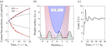


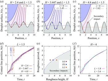


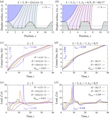


 Open access