





Introduction
A typical snowpack can be characterized in terms of some physical parameters [Reference Fierz, Armstrong, Durand, Etchevers, Greene, McClung, Nishimura, Satyawali and Sokratov1, Reference Sturm, Taras, Liston, Derksen, Jonas and Lea2]. Among the others, the snowpack depth, the bulk density, liquid water content (LWC), and snow water equivalent (SWE) can be important inputs for models used to determine the risk of avalanches and floods, and to manage the hydrological resources [Reference Viviroli, Archer, Buytaert, Fowler, Greenwood, Hamlet, Huang, Koboltschnig, Litaor, López-Moreno, Lorentz, Schädler, Schreier, Schwaiger, Vuille and Woods3–Reference Prasch, Mauser and Weber7]. Therefore, the possibility to monitor these physical parameters is extremely useful. To accomplish this task, a number of techniques exist. First, manual snowpits represent the golden standard [Reference Fierz, Armstrong, Durand, Etchevers, Greene, McClung, Nishimura, Satyawali and Sokratov1]. Although very precise, this analysis is time consuming and costly. For a single snowpit, it may take 1 or 2 h, and normally two qualified technicians. Moreover, it is applicable only to sites where reasonable safety margins can be guaranteed for the involved staff. Thus, both the time and spatial resolution and repetition of this technique are far from the optimum in several applications.
For these reasons, other solutions can be considered to complement and/or augment the results given by manual snowpits. Among them, ground-based microwave radars exhibit several advantages, including the reasonable cost, the fast and non-destructive measurement, and the possibility of installation either above the ground, mainly for portable instruments, or buried, mainly for monitoring critical steep slopes along the avalanche path [Reference Marshall and Koh8–Reference Okorn, Brunnhofer, Platzer, Heilig, Schmid, Mitterer, Schweizer and Eisenb10]. However, when microwave radars are used to monitor the snowpack, the transformation from the time domain (i.e. the time-of-flight recorded by the radar) and the space domain (i.e. the target-radar distance, in this case, for example, the distance between the radar and the snow–ground interface, thus the snowpack depth) is ill-posed. This is because, normally, the wave speed in the snowpack is unknown. Traditionally, this aspect has been solved proposing different approaches: a-priori assumptions on the density of the snowpack; measuring one of the physical parameters, such as the snowpack depth or density, using additional instruments or techniques to measure other parameters than the radar (e.g. ultrasonic or laser gauges, GPS receivers, density probes during manual snowpits); applying complicated post-processing techniques, based, for example, on inverse-scattering approaches or on the reconstruction of the diffraction parabola [Reference Bradford, Harper and Brown11–Reference Griessinger, Mohr and Jonas15]. However, all these solutions invariably exhibit some flaws. A-priori assumptions can lead to large errors. Additional instruments or techniques imply more complex systems and jeopardize the natural advantages of microwave radars (e.g. manual snowpits mean slow and destructive measurements, additional devices most often require fixed installation), which consequently become less suitable for portable applications or for installation along avalanche paths. Post-processing techniques may require the movement of the radar along a dedicated path, and are prone to problems such as local minima, artefacts, and so on.
To solve these limitations, a novel microwave radar architecture has been proposed recently, and the working principle is demonstrated experimentally [Reference Pasian, Barbolini, Dell'Acqua, Espín-López and Silvestri16]. One of the key points is the use of one transmitting antenna and two receiving antennas, in such a way that two independent radar profiles are collected, and used in a joint mathematical system to determine, at the same time, the snowpack depth and the wave speed into the snowpack. Then, using formulations available from the literature, this information is used to determine the physical parameters of the snowpack [Reference Hallikainen, Ulaby and Abdelrazik17].
While [Reference Pasian, Barbolini, Dell'Acqua, Espín-López and Silvestri16] is focused on the demonstration of the working principle, this paper presents the aspects related to the physical implementation of this novel radar architecture. An earlier version of this paper was presented at the 13th European Conference on Antennas and Propagation (EuCAP 2019) [Reference Pasian, Espin-Lopez, Barbolini and Dell'Acqua18]. First, a comparison between two different schemas is discussed, either using only one physical receiving antenna to mime the virtual presence of the required two receiving antennas, or using two physical receiving antennas. Second, the implementation with two physical receiving antennas is verified experimentally with a dedicated extensive campaign (5 days, approximately 30 comparisons between radar measurements and ground truth, the latter by means of manual snowpit analysis), assessing the radar performance. Third, the impact of the non-flatness of the terrain is discussed, along with a mitigation strategy. This paper is organized as follows. “Radar architecture” section summarizes the most important aspect of the radar architecture, while “Radar implementation” section describes the two possible implementations, addressing advantages and disadvantages. Finally, “Experimental validation” section presents the experimental results.
Radar architecture
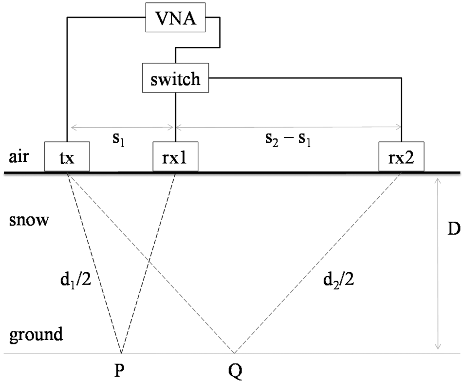
The details of the radar architecture are described in [Reference Pasian, Barbolini, Dell'Acqua, Espín-López and Silvestri16], but for the sake of completeness, the key points are summarized as follows. The general schema comprises one transmitting antenna “tx” and two receiving antennas, “rx1” and “rx2”, as shown in Fig. 1. This creates two independent radar paths, from “tx” to “rx1”, and from “tx” to “rx2”. The horizontal separation between “tx” and “rx1” and “rx2” is s 1 and s 2, respectively. The signal collected by each receiving antenna is processed according to the standard frequency modulated continuous wave (FMCW) radar scheme. This delivers the time-of-flight T1 and T2 from the transmitting to the receiving antennas, following a path described by a distance d 1 and d 2 for the receiving antennas “rx1” and “rx2”, respectively. The times-of-flight are proportional to the snowpack depth D, in accordance with the wave speed v in the snowpack. Overall, thanks to the presence of two independent radar paths, it is possible to have a well-posed mathematical system, with two independent equations and two unknowns, the snowpack depth D and the wave speed v in the snowpack. Then, for dry snow, the wave speed v can be directly translated into the real part of the relative dielectric permittivity (ε’) of the snowpack, and in turn into the snowpack density (ρ), using the following equation [Reference Hallikainen, Ulaby and Abdelrazik17]:

where ρ is measured in kg/m3.
Schema of the radar architecture.

Radar implementation
One receiving antenna
The physical modifications that transform the snowpack structure normally occur according to a time scale, a few hours, much slower compared to the time required by the microwave signal to travel from the transmitting to the receiving antenna, in the order of a few nanoseconds for normal snowpacks. Even considering the entire process of obtaining a FMCW radar measurement of a snowpack, which may include, for example, the sweep across the frequency spectrum used to generate the FMCW radar signal, this is strongly dependent upon the hardware implementation (e.g. the intermediate frequency and the number of frequency points), but in any case normally does not exceed 1 s. Therefore, this aspect can be used to simplify the radar implementation with respect to the schema reported in Fig. 1, as shown in Fig. 2.
Schema of the radar architecture for the implementation A.

In particular, just one receiving antenna is physically present. This antenna is first positioned at a pre-determined distance s 1 from the transmitting antenna, and the radar signal is collected. This mimes the receiving antenna “rx1”. Then, the antenna is moved to the second pre-determined distance s 2 from the transmitting antenna, and the radar signal is collected again. This mimes the receiving antenna “rx2”. Since the entire process is expected to take not more than 1 or 2 min, in the meantime the snowpack properties (e.g. density and depth) are unchanged.
The complete setup is shown in Fig. 3. It comprises a vector network analyzer (VNA) from Keysight (FieldFox N9916A, Santa Rosa, CA, USA) used to generate the transmit signal and to receive the backscattered echo, two open-ended WR340 waveguide antennas, working in S band (2–3.5 GHz), and two coaxial cables to connect the antennas with the VNA, 2 m long each. The antennas are mounted on a metal rail, to ease the movement of the receiving antenna from the first to the second position. The processing of the signal is performed on a standard laptop set.
Photograph of the implementation A, with one receiving antenna.

Two receiving antennas
In this case, two receiving antennas are physically present. This means that the schema shown in Fig. 1 is replicated, and the radar signals at the first and second pre-determined distances s 1 and s 2 are collected almost simultaneously, as shown in Fig. 4. The complete setup is shown in Fig. 5. Also in this case, it comprises a VNA from Keysight (FieldFox N9916A) used to generate the transmit signal and to receive the backscattered echo. This time, three open-ended WR340 waveguide antennas, working in S band (2–3.5 GHz), and three coaxial cables to connect the antennas with the VNA, 2 m long each, are used. The antennas are mounted on a different wooden rail, to stabilize as much as possible the antenna placement. To let the three antennas communicate with the two-port VNA, a manual switch is used. Actually, the manual switch is the only element that prevents a perfect simultaneous collection of the two radar signals. Indeed, first the signal is collected at the receiving antenna “rx1”, then the switch is operated, and the signal is collected at the receiving antenna “rx2”. The temporal distance between the two measurements is in the order of a few seconds. In this case, the processing of the signal is performed on a dedicated Raspberry Pi equipped with a touch screen (referred to as a tablet in Fig. 5).
Schema of the radar architecture for the implementation B.
Photograph of the implementation B with two receiving antennas, general view and (inset) magnified view on the switch.

Comparison between the two implementations
From a theoretical perspective, both implementations are theoretically correct. They both refer to a downward-looking scenario, where the microwave radar is placed above the snowpack pack, at the snow–air interface. Thus, this mimes portable applications, as described in the “Introduction” section. Nevertheless, the same radar architecture can be used according to an upward-looking scenario, where the microwave radar is placed under the snowpack, close to the snow–ground interface, to address fixed-point buried applications.
When the experimental setup is very well controlled (e.g. a laboratory setup where the snowpack is mimed using stratification of cork and polystyrene [Reference Espin-Lopez, Pasian, Barbolini and Dell'Acqua19]), and all fine movements can be accomplished with extreme care, the accuracy of the results is comparable. Instead, for real field tests, the two implementations exhibit their own advantages and disadvantages.
Implementation A is lighter and less cumbersome, because the number of antennas is at the minimum, and the metal rail can be easily dismounted for transportation. On the other hand, even if the rail is designed to let the antennas sliding on it to be moved along the different receiving positions, it is very difficult to maintain a perfect stability of the overall setup when it lays on a relatively soft medium, such as snow. In practical terms, an error better than 2–3 mm for the antenna positioning is challenging to achieve. Implementation B comprises one antenna more, and a different wooden rail, heavier and more cumbersome with respect to the previous case. This is a disadvantage during transportation, an aspect that cannot be underestimated for a portable device. On the other hand, the physical presence of three antennas, which do not require movements other than the selector of the switch, allows for using a rail with pre-determined antenna locations, in such a way that a practically near-to-perfect placement can be achieved. In fact, for implementation B, the real limit is given by the mechanical switch.
To understand its impact, a complete characterization of the transmission coefficient from the VNA port to the first output port and from the VNA port to the second output port is performed. Figure 6 shows the difference between the two output channels in terms of magnitude (ΔM) and phase (ΔP), and in terms of equivalent virtual displacement (ΔD). The latter is calculated as:

where λ is the operating wavelength. It can be appreciated that a maximum difference of 0.05 dB, 3.8 degrees, and 0.9 mm is measured for the magnitude (ΔM), phase (ΔP), and equivalent virtual displacement (ΔD), respectively. For this reason (a virtual error on the antenna placement two/three times better than the physical error on the antenna placement for the case of one physical receiving antenna), for the experimental validation presented in “Experimental validation”, the configuration employing two physical receiving antennas is preferred.
Transmission coefficient of the switch. Difference between the channel from the VNA port to the first output port and from the VNA port the second output port: (a) magnitude; (b) phase; (c) equivalent virtual displacement.

Experimental validation
A dedicated field campaign was performed to experimentally assess the performance of the novel radar architecture. Indeed, even if the working principle was experimentally demonstrated in the previous works [Reference Pasian, Barbolini, Dell'Acqua, Espín-López and Silvestri16], an extensive field campaign is required to determine the precision and accuracy of the proposed radar architecture against different field conditions. For example, the flatness of the snow–ground interface, as schematically depicted in Fig. 4, is important for the correct timing of the two times-of-flight between the transmitter and the receivers. However, real field conditions impose unavoidable, and unknown, irregularities of the terrain, which are translated into irregularities of the snow–ground interface, as shown in Fig. 7. For typical configurations of the radar architecture (s 1 in the order of 30–40 cm, s 2 in the order of 70–80 cm) and typical snowpacks with dry snow (snowpack depth in the order of 100 cm, and bulk density in the order 250–300 kg/m3), the difference between d 1 and d 2 is in the order of 10 cm.
Schema of the radar architecture for the implementation B, exemplifying the non-flatness of the terrain.

This means that irregularities of the terrain in the order of 1 cm along the central part of the footprint of the radar, which is the part of the terrain between points P and Q in Fig. 7 (e.g. when s 1 = 30 cm and s 2 = 70 cm, the two ideal points P and Q in Fig. 7 are separated by a distance of 20 cm), may be responsible for errors in the measurement of the times-of-flight in the order of 10%. It is also worth noting that this aspect is peculiar of the downward-looking cases, as for the other case of upward-looking radars, for most of the snowpacks, the snow–air interface can be considered practically flat. Nevertheless, for portable applications, working in downward-looking configuration, this is a relevant aspect, which must be accounted for to determine the potential performance of the radar architecture for real applications. Fortunately, the irregularities of the terrain can be considered randomly distributed. Therefore, these are partially compensated repeating the radar measurements a number of times (for the results presented in this paper, logistics aspects normally dictated five or six times), slightly changing the position of the radar at the snow–air interface, and averaging the results, as exemplified in Fig. 8. It is interesting to observe that the proposed radar architecture, which is completely self-standing, as outlined in “Introduction” and “Radar architecture” sections, provides a natural execution for this repeated measurement, as the entire radar measurement is simply repeated at different places of the snow–air interface in just a few minutes. This is well in line with the portable applications, where an operator is supposed to rapidly take multiple measurements at different locations of interest. To highlight the effects of this important step, the following results are presented both individually for each single radar measurement, and averaged.
Example of multiple placing of the radar at the top of the snowpack.

The field campaign took place at an altitude of around 2500 m above sea level, in the Italian Alps (45°40′10″N, 7°18′30″E), for five consecutive days from 4 February to 8 February 2019. The selected slope exhibits a North orientation, with no direct sunlight during measurements. During the entire campaign, the snow was dry. To validate the radar measurements, these were compared with manual snowpits. Thus, the snowpack under each site selected for a radar measurement was analyzed after the radar measurement digging the snowpack itself to the ground and performing a manual snowpit analysis, according to standard procedures [Reference Fierz, Armstrong, Durand, Etchevers, Greene, McClung, Nishimura, Satyawali and Sokratov1].
In particular, the snowpack depth D and bulk density ρ are manually measured. The former is measured with a precision outdoor ruler, the latter using a density cutter with a volume of 198 cm3 and sampling the snowpack with a vertical resolution of 10 cm, averaging all the measurements for obtaining the bulk density. Then, the SWE is a by-product that can be calculated as [Reference Sturm, Taras, Liston, Derksen, Jonas and Lea2]:

where ρw is the density of water, 1000 kg/cm3. Concerning the real part of the dielectric permittivity (for simplicity, dielectric constant), also in this case, for the manual snowpit analysis, this is a by-product, which is calculated using (1), once the bulk density is measured.
Instead, as briefly summarized in “Radar architecture” section and reported in detail in [Reference Pasian, Barbolini, Dell'Acqua, Espín-López and Silvestri16], the radar measurements directly provide the snowpack depth and dielectric constant. Then, for the radar, the bulk density is a by-product, which is calculated using (1), once the dielectric constant is measured. For the SWE, this is calculated also for the radar measurements using (3).
Figure 9 reports the comparison, measurement by measurement, between the results obtained using the radar and the results obtained from the manual snowpit analysis (ground truth). Overall, 28 different tests can be observed. Figure 10 reports the comparison, day-by-day, between the results obtained using the radar and the results obtained from the manual snowpit analysis (ground truth). Overall, five different tests can be observed. As explained in this same section, each day-based radar measurement is obtained averaging a defined number (normally five or six) of single measurement presented in Fig. 9, slightly changing the position of the radar at the snow–air interface (Fig. 8), with the aim of averaging out the effect of the non-flatness of the terrain. Overall, the results are summarized in Table 1 in terms of root mean square error (RMSE) and in terms of relative dispersion with respect to the mean of each parameter.
Single-based comparison between the radar measurement (white dots) and the manual snowpit analysis (dashed line): (a) depth; (b) dielectric constant; (c) density; (d) SWE.

Day-based comparison between the radar measurement (white dots) and the manual snowpit analysis (dashed line): (a) depth; (b) dielectric constant; (c) density; (d) SWE.

Root mean square error (RMSE) and percentage error for the radar measurements against manual snowpit analysis

First, it can be appreciated that in all cases, better results are achieved for snowpack depth and dielectric constant. This is in line with the working principle of the radar architecture, which measures directly these two parameters. Then, as explained above, the by-product parameters for the radar measurement, i.e. density and SWE, naturally exhibit a larger RMSE because of equations (1) and (3), respectively, used to calculate them starting from the snowpack depth and dielectric constant. In particular, the RMSE on the dielectric constant is enlarged by the inversion of (1), while the RMSE of both depth and density combine themselves in (3).
Second, it can be appreciated for the improvement provided by the averaging procedure described above. It is worth noting that either single-based or day-based approaches can be used, according to the application. In particular, if a specific site shall be monitored with best accuracy, then the averaging procedure will be very effective, at the cost of longer measurement times during the repetition. In this case (i.e. specific site), particular attention should be paid to those situations where the measures can be jeopardized by external factors. A typical case is when the non-flatness of the terrain is particularly pronounced (e.g. because of a large rock on the ground). Another issue can arise when the internal stratigraphy of the snowpack returns strong, multiple echoes masking the main reflection from the snow–ground interface (e.g. an ice layer at half-depth in the snowpack, whose multiple reflections could coincide with the full-depth reflection from the ground). Finally, in some cases, the snow–ground interface may be relatively smooth, generating a weak reflection, which can be difficult to identify and/or not particularly sharp, thus complicating the identification of the correct time-of-flight.
Instead, if the radar is used to monitor an entire mountain catchment, for example, to determine the total amount of equivalent water, then a large number of single-based radar measurements, done at several different locations along the mountain catchment itself, will provide a reasonable compromise between rapidity and accuracy.
Conclusion
This paper presented the statistical validation for a novel type of radar architecture designed for snowpack monitoring. Experimental measurement during a 5-day campaign in winter 2019 in the Italian Alps, on dry snow, are discussed, with particular attention to an operative strategy that can be applied to mitigate the effects caused by the non-flatness of the terrain. Two different practical implementations of the radar were outlined, either based on one physical antenna to mime the virtual presence of two receiving antennas (more compact), or based on two physical receiving antennas (more precise).
The latter showed RMSEs, calculated against the ground truth (manual snowpit analysis) of around 3.5 cm, 0.05, 27 kg/m3, and 2.5 cm for the determined snowpack depth, dielectric constant, bulk density, and SWE, respectively. This translated into relative errors better than 5% for the depth and the dielectric constant, and approximately 10% for the bulk density and the SWE. Overall, this proved the practical applicability of this new radar architecture, which is capable of determining several different physical parameters of the snowpack without any complementary device or technique.
Acknowledgement
This work was supported by the Italian Ministry of Education, University and Scientific Research (MIUR) under the project SIR “SNOWAVE” RBSI148WE5. The authors would like to thank Fondazione Montagna Sicura – Montagne Sûre, Regione Autonoma Valle d'Aosta – Région Autonome Vallée d'Aoste, and Centro Addestramento Alpino of the Italian Army, for the fruitful collaboration.
 Marco Pasian was born in 1980. He received the M.Sc. degree (cum laude) in electronic engineering and the Ph.D. degree in electronics and computer science from the University of Pavia, Pavia, Italy, in 2005 and 2009, respectively. He held a post-doctoral position with the University of Pavia, from 2009 to 2013. Since 2013, he has been an Assistant Professor with the Microwave Laboratory, University of Pavia, where he has been on a 3-year tenure-track position for an Associate Professor since 2017. Dr. Pasian is a EuMA Member and an IEEE Senior Member. He is an Associate Editor of the EuMA International Journal of Microwave and Wireless Technologies, and of the IEEE Journal of Electromagnetics, RF and Microwaves in Medicine and Biology. He is the Principal Investigator of SNOWAVE, a project on the use of microwaves for snowpack monitoring funded by a competitive grant from the Italian Ministry of Education, University, and Research under the funding schema Scientific Independence of Young Researchers.
 Pedro Fidel Espín-López was born in Murcia, Spain, in 1989. He received the M.S. degree in electronic engineering from the Technical University of Cartagena, Spain, in 2015. From May 2015, he joined the European Institute of Oncology (IEO) as a research fellow. His work was focused on the study of non-ionizing dosimetry and the assessment of safety for a breast cancer detection system using millimeter and sub-millimeter waves. He is working toward the Ph.D. degree in electronics at the University of Pavia and his research activities are focused on the study and development of microwave and millimeter wave antenna systems. Currently, he is working at the Centre Tecnològic de Telecomunicacions de Catalunya (CTTC) as a Research Assistant in the Geomatic Division.
 Lorenzo Silvestri was born in Novara, Italy, in 1987. He received the Master's degree in electronic engineering from the University of Pavia, Pavia, Italy, in 2014. In 2014, he was an Exchange Student with the University of Ghent, Ghent, Belgium. He is currently a Ph.D. Student with the Department of Computer, Electronics, and Biomedical Engineering, University of Pavia. His research interests include the development of new components based on substrate-integrated waveguide technology on innovative substrate materials. Dr. Silvestri was a recipient of the Best Paper Award at the 15th Mediterranean Microwave Symposium (MMS2015).
 Massimiliano Barbolini is an Adjunct Professor of the master degree course for civil and environmental engineer “snow avalanches and related mountain natural hazard” with the University of Pavia, Pavia, Italy. He is a Co-Founder and a CTO of the consulting company Flow-Ing s.r.l., La Spezia, Italy, focused on engineering studies and projects for natural hazard mitigation as well as on applied research. He has been participating in several research projects in the field of mountain natural hazards either at national or European level. The outcomes of his research have been published in international journals and conference proceedings. He has co-authored technical guidelines at national and European level. Dr. Barbolini is a member of editorial boards of international journals and conferences.
 Fabio Dell'Acqua is an Associate Professor of remote sensing with the Department of Electrical, Computer and Biomedical Engineering, University of Pavia, Pavia, Italy. In 2014, he co-founded a University spin-off company, named Ticinum Aerospace, Pavia, to exploit commercially his research results in the use of EO data for risk management. In his research area, he is participating in, or leading, several research projects, both at the national and international level. His research interests include radar/optical data fusion for risk-related applications. Prof. Dell'Acqua is a Life Member of the Technical and Scientific Board of the Lombardy Aerospace Industry Cluster.


 Open access

