





1 Introduction
Laser wakefield acceleration (LWFA) enables compact generation of high-energy electron beams[
Reference Tajima and Dawson1], which are driving advances in several fields. LWFA electron beams are being used to develop compact free-electron lasers (FELs) that produce ultrashort, high-brilliance X-ray and infrared (IR) radiation[
Reference Galletti, Assmann, Couprie, Ferrario, Giannessi, Irman, Pompili and Wang2–
Reference André, Andriyash, Loulergue, Labat, Roussel, Ghaith, Khojoyan, Thaury, Valléau, Briquez, Marteau, Tavakoli, N’Gotta, Dietrich, Lambert, Malka, Benabderrahmane, Vétéran, Chapuis, Ajjouri, Sebdaoui, Hubert, Marcouillé, Berteaud, Leclercq, Ajjouri, Rommeluère, Bouvet, Duval, Kitegi, Blache, Mahieu, Corde, Gautier, Phuoc, Goddet, Lestrade, Herbeaux, Évain, Szwaj, Bielawski, Tafzi, Rousseau, Smartsev, Polack, Dennetière, Bourassin-Bouchet, De Oliveira and Couprie4]. These electron beams also serve as sources for secondary particles and radiation, including high-quality positron beams[
Reference Sarri, Schumaker, Di Piazza, Vargas, Dromey, Dieckmann, Chvykov, Maksimchuk, Yanovsky, He, Hou, Nees, Thomas, Keitel, Zepf and Krushelnick5,
Reference Sarri, Poder, Cole, Schumaker, Di Piazza, Reville, Dzelzainis, Doria, Gizzi, Grittani, Kar, Keitel, Krushelnick, Kuschel, Mangles, Najmudin, Shukla, Silva, Symes, Thomas, Vargas, Vieira and Zepf6], high-energy photons[
Reference Corde, Phuoc, Lambert, Fitour, Malka, Rousse, Beck and Lefebvre7–
Reference Cole, Behm, Gerstmayr, Blackburn, Wood, Baird, Duff, Harvey, Ilderton, Joglekar, Krushelnick, Kuschel, Marklund, McKenna, Murphy, Poder, Ridgers, Samarin, Sarri, Symes, Thomas, Warwick, Zepf, Najmudin and Mangles10] and even muons[
Reference Dreesen, Green, Browder, Wood, Schwellenbach, Ditmire, Tiwari and Wagner11–
Reference Terzani, Kisyov, Greenberg, Le Pottier, Mironova, Picksley, Stackhouse, Hai-En Tsai, Rockafellow, Miao, Shrock, Heim, Garcia-Sciveres, Benedetti, Valentine, Milchberg, Nakamura, Gonsalves, van Tilborg, Schroeder, Esarey and Geddes13], enabling applications in fundamental physics[
Reference Poder, Tamburini, Sarri, Di Piazza, Kuschel, Baird, Behm, Bohlen, Cole, Corvan, Duff, Gerstmayr, Keitel, Krushelnick, Mangles, McKenna, Murphy, Najmudin, Ridgers, Samarin, Symes, Thomas, Warwick and Zepf14,
Reference Gonoskov, Blackburn, Marklund and Bulanov15], such as probing techniques[
Reference Zhang, Hua, Wan, Pai, Guo, Zhang, Ma, Li, Wu, Chu, Gu, Xu, Mori, Joshi, Wang and Lu16–
Reference Russell, Campbell, Qian, Cardarelli, Bulanov, Bulanov, Grittani, Seipt, Willingale and Thomas18], as well as in radiotherapy[
Reference Labate, Palla, Panetta, Avella, Baffigi, Brandi, Di Martino, Fulgentini, Giulietti, Köster, Terzani, Tomassini, Traino and Gizzi19–
Reference Zhou, Guo, Wan, Liu, Peng, Hua and Lu21]. Furthermore, the extremely high acceleration gradients achievable with LWFA –
${10}^3$
 times higher than in conventional radio frequency (RF) accelerators[
Reference Degiovanni, Wuensch and Navarro22], allowing acceleration to multi-GeV energies in sub-meter-scale plasma[
Reference Leemans, Nagler, Gonsalves, Tóth, Nakamura, Geddes, Esarey, Schroeder and Hooker23–
Reference Aniculaesei, Ha, Yoffe, Labun, Milton, McCary, Spinks, Quevedo, Labun, Sain, Hannasch, Zgadzaj, Pagano, Franco-Altamirano, Ringuette, Gaul, Luedtke, Tiwari, Ersfeld, Brunetti, Ruhl, Ditmire, Bruce, Donovan, Downer, Jaroszynski and Hegelich26] – open the door to next-generation high-energy particle colliders, potentially reducing the size and cost of future TeV-scale accelerators[
Reference Schroeder, Esarey, Geddes, Benedetti and Leemans27].
times higher than in conventional radio frequency (RF) accelerators[
Reference Degiovanni, Wuensch and Navarro22], allowing acceleration to multi-GeV energies in sub-meter-scale plasma[
Reference Leemans, Nagler, Gonsalves, Tóth, Nakamura, Geddes, Esarey, Schroeder and Hooker23–
Reference Aniculaesei, Ha, Yoffe, Labun, Milton, McCary, Spinks, Quevedo, Labun, Sain, Hannasch, Zgadzaj, Pagano, Franco-Altamirano, Ringuette, Gaul, Luedtke, Tiwari, Ersfeld, Brunetti, Ruhl, Ditmire, Bruce, Donovan, Downer, Jaroszynski and Hegelich26] – open the door to next-generation high-energy particle colliders, potentially reducing the size and cost of future TeV-scale accelerators[
Reference Schroeder, Esarey, Geddes, Benedetti and Leemans27].
The electron energy gain in LWFA is primarily limited by laser diffraction, pulse depletion and dephasing. To overcome diffraction and maximize energy gain, several guiding techniques have been developed. One approach is self-guiding, where an ultra-high-intensity laser pulse creates its own plasma channel via relativistic and ponderomotive self-focusing, balancing diffraction and enabling propagation over several Rayleigh lengths[ Reference Clayton, Ralph, Albert, Fonseca, Glenzer, Joshi, Lu, Marsh, Martins, Mori, Pak, Tsung, Pollock, Ross, Silva and Froula24, Reference Aniculaesei, Ha, Yoffe, Labun, Milton, McCary, Spinks, Quevedo, Labun, Sain, Hannasch, Zgadzaj, Pagano, Franco-Altamirano, Ringuette, Gaul, Luedtke, Tiwari, Ersfeld, Brunetti, Ruhl, Ditmire, Bruce, Donovan, Downer, Jaroszynski and Hegelich26, Reference Kim, Pae, Cha, Kim, Yu, Sung, Lee, Jeong and Lee28]. However, it is a nonlinear process that is highly dependent on plasma density, which can limit controllability, stability and efficiency. In contrast, pre-formed plasma channels, created in advance using methods such as optical-field ionization (OFI)[ Reference Miao, Shrock, Feder, Hollinger, Morrison, Nedbailo, Picksley, Song, Wang, Rocca and Milchberg25, Reference Morozov, Goltsov, Chen, Scully and Suckewer29– Reference Rockafellow, Shrock, Miao, Sloss, Le, Hancock, Zahedpour, Hollinger, Wang, King, Zhang, Šišma, Grittani, Versaci, Gordon, Williams, Reagan, Rocca and Milchberg43] or capillary discharge[ Reference Leemans, Nagler, Gonsalves, Tóth, Nakamura, Geddes, Esarey, Schroeder and Hooker23, Reference Bobrova, Esaulov, Sakai, Sasorov, Spence, Butler, Hooker and Bulanov44– Reference Gonsalves, Nakamura, Daniels, Benedetti, Pieronek, de Raadt, Steinke, Bin, Bulanov, van Tilborg, Geddes, Schroeder, Tóth, Esarey, Swanson, Fan-Chiang, Bagdasarov, Bobrova, Gasilov, Korn, Sasorov and Leemans48], provide a stable, low-density guiding structure without reliance on nonlinear propagation effects. In LWFA, this enables propagation over much longer distances (from tens of centimeters to meters) and supports higher electron energies[ Reference Miao, Shrock, Feder, Hollinger, Morrison, Nedbailo, Picksley, Song, Wang, Rocca and Milchberg25, Reference Picksley, Stackhouse, Benedetti, Nakamura, Tsai, Li, Miao, Shrock, Rockafellow, Milchberg, Schroeder, van Tilborg, Esarey, Geddes and Gonsalves41, Reference Rockafellow, Miao, Shrock, Sloss, Le, Hancock, Zahedpour, Hollinger, Wang, King, Zhang, Šišma, Grittani, Versaci, Gordon, Williams, Reagan, Rocca and Milchberg42, Reference Gonsalves, Nakamura, Daniels, Benedetti, Pieronek, de Raadt, Steinke, Bin, Bulanov, van Tilborg, Geddes, Schroeder, Tóth, Esarey, Swanson, Fan-Chiang, Bagdasarov, Bobrova, Gasilov, Korn, Sasorov and Leemans48] by enabling acceleration at lower plasma densities. Pre-formed channels also offer better control over the plasma density profile, matched laser spot size and overall stability, reducing shot-to-shot fluctuations and improving beam quality[ Reference Shrock, Rockafellow, Miao, Le, Hollinger, Wang, Gonsalves, Picksley, Rocca and Milchberg39, Reference Tripathi, Miao, Sloss, Rockafellow, Shrock, Hancock and Milchberg49].
The first plasma waveguides were demonstrated in high-density plasma using inverse Bremsstrahlung heating[
Reference Durfee and Milchberg50,
Reference Durfee, Lynch and Milchberg51]. This heating mechanism is inefficient and unsuitable for the low plasma densities required for multi-GeV LWFA[
Reference Miao, Shrock, Feder, Hollinger, Morrison, Nedbailo, Picksley, Song, Wang, Rocca and Milchberg25,
Reference Picksley, Stackhouse, Benedetti, Nakamura, Tsai, Li, Miao, Shrock, Rockafellow, Milchberg, Schroeder, van Tilborg, Esarey, Geddes and Gonsalves41,
Reference Rockafellow, Miao, Shrock, Sloss, Le, Hancock, Zahedpour, Hollinger, Wang, King, Zhang, Šišma, Grittani, Versaci, Gordon, Williams, Reagan, Rocca and Milchberg42], as it cannot achieve on-axis densities below
${10}^{17}$
 cm
${}^{-3}$
cm
${}^{-3}$
 . However, extending the method to use density-independent OFI as the heating mechanism[
Reference Lemos, Cardoso, Geada, Figueira, Albert and Dias30–
Reference Smartsev, Caizergues, Oubrerie, Gautier, Goddet, Tafzi, Phuoc, Malka and Thaury32,
Reference Miao, Feder, Shrock, Goffin and Milchberg34,
Reference Feder, Miao, Shrock, Goffin and Milchberg35,
Reference Corkum, Burnett and Brunel52], together with auxiliary ionization of the neutral shock to form the cladding[
Reference Morozov, Goltsov, Chen, Scully and Suckewer29,
Reference Miao, Feder, Shrock, Goffin and Milchberg34,
Reference Feder, Miao, Shrock, Goffin and Milchberg35,
Reference Picksley, Alejo, Shalloo, Arran, von Boetticher, Corner, Holloway, Jonnerby, Jakobsson, Thornton, Walczak and Hooker37,
Reference Shrock, Miao, Feder and Milchberg38], has enabled the production of highly confining, meter-scale plasma waveguides with on-axis densities below
${10}^{17}$
. However, extending the method to use density-independent OFI as the heating mechanism[
Reference Lemos, Cardoso, Geada, Figueira, Albert and Dias30–
Reference Smartsev, Caizergues, Oubrerie, Gautier, Goddet, Tafzi, Phuoc, Malka and Thaury32,
Reference Miao, Feder, Shrock, Goffin and Milchberg34,
Reference Feder, Miao, Shrock, Goffin and Milchberg35,
Reference Corkum, Burnett and Brunel52], together with auxiliary ionization of the neutral shock to form the cladding[
Reference Morozov, Goltsov, Chen, Scully and Suckewer29,
Reference Miao, Feder, Shrock, Goffin and Milchberg34,
Reference Feder, Miao, Shrock, Goffin and Milchberg35,
Reference Picksley, Alejo, Shalloo, Arran, von Boetticher, Corner, Holloway, Jonnerby, Jakobsson, Thornton, Walczak and Hooker37,
Reference Shrock, Miao, Feder and Milchberg38], has enabled the production of highly confining, meter-scale plasma waveguides with on-axis densities below
${10}^{17}$
 cm
${}^{-3}$
cm
${}^{-3}$
 . These free-standing waveguides are immune to laser damage, longitudinally tunable[
Reference Shrock, Rockafellow, Miao, Le, Hollinger, Wang, Gonsalves, Picksley, Rocca and Milchberg39,
Reference Tripathi, Miao, Sloss, Rockafellow, Shrock, Hancock and Milchberg49] and can reliably reach the low densities required for high-energy acceleration[
Reference Miao, Shrock, Feder, Hollinger, Morrison, Nedbailo, Picksley, Song, Wang, Rocca and Milchberg25,
Reference Picksley, Stackhouse, Benedetti, Nakamura, Tsai, Li, Miao, Shrock, Rockafellow, Milchberg, Schroeder, van Tilborg, Esarey, Geddes and Gonsalves41,
Reference Rockafellow, Miao, Shrock, Sloss, Le, Hancock, Zahedpour, Hollinger, Wang, King, Zhang, Šišma, Grittani, Versaci, Gordon, Williams, Reagan, Rocca and Milchberg42] using gas jet technology[
Reference Shrock, Miao, Feder and Milchberg38,
Reference Lorenz, Grittani, Chacon-Golcher, Lazzarini, Limpouch, Nawaz, Nevrkla, Vilanova and Levato53,
Reference Miao, Shrock, Rockafellow, Sloss and Milchberg54]. In contrast, capillary-based waveguides are limited by their fixed geometry and susceptibility to laser-induced damage[
Reference Pieronek, Gonsalves, Benedetti, Bulanov, van Tilborg, Bin, Swanson, Daniels, Bagdasarov, Bobrova, Gasilov, Korn, Sasorov, Geddes, Schroeder, Leemans and Esarey55], and the inability to reach densities as low as approximately
$1\times {10}^{17}\ {\mathrm{cm}}^{-3}$
. These free-standing waveguides are immune to laser damage, longitudinally tunable[
Reference Shrock, Rockafellow, Miao, Le, Hollinger, Wang, Gonsalves, Picksley, Rocca and Milchberg39,
Reference Tripathi, Miao, Sloss, Rockafellow, Shrock, Hancock and Milchberg49] and can reliably reach the low densities required for high-energy acceleration[
Reference Miao, Shrock, Feder, Hollinger, Morrison, Nedbailo, Picksley, Song, Wang, Rocca and Milchberg25,
Reference Picksley, Stackhouse, Benedetti, Nakamura, Tsai, Li, Miao, Shrock, Rockafellow, Milchberg, Schroeder, van Tilborg, Esarey, Geddes and Gonsalves41,
Reference Rockafellow, Miao, Shrock, Sloss, Le, Hancock, Zahedpour, Hollinger, Wang, King, Zhang, Šišma, Grittani, Versaci, Gordon, Williams, Reagan, Rocca and Milchberg42] using gas jet technology[
Reference Shrock, Miao, Feder and Milchberg38,
Reference Lorenz, Grittani, Chacon-Golcher, Lazzarini, Limpouch, Nawaz, Nevrkla, Vilanova and Levato53,
Reference Miao, Shrock, Rockafellow, Sloss and Milchberg54]. In contrast, capillary-based waveguides are limited by their fixed geometry and susceptibility to laser-induced damage[
Reference Pieronek, Gonsalves, Benedetti, Bulanov, van Tilborg, Bin, Swanson, Daniels, Bagdasarov, Bobrova, Gasilov, Korn, Sasorov, Geddes, Schroeder, Leemans and Esarey55], and the inability to reach densities as low as approximately
$1\times {10}^{17}\ {\mathrm{cm}}^{-3}$
 [
Reference Gonsalves, Nakamura, Daniels, Benedetti, Pieronek, de Raadt, Steinke, Bin, Bulanov, van Tilborg, Geddes, Schroeder, Tóth, Esarey, Swanson, Fan-Chiang, Bagdasarov, Bobrova, Gasilov, Korn, Sasorov and Leemans48]. Electron energies of up to 8 GeV have been achieved using capillary discharge waveguides enhanced with auxiliary laser heating[
Reference Gonsalves, Nakamura, Daniels, Benedetti, Pieronek, de Raadt, Steinke, Bin, Bulanov, van Tilborg, Geddes, Schroeder, Tóth, Esarey, Swanson, Fan-Chiang, Bagdasarov, Bobrova, Gasilov, Korn, Sasorov and Leemans48].
[
Reference Gonsalves, Nakamura, Daniels, Benedetti, Pieronek, de Raadt, Steinke, Bin, Bulanov, van Tilborg, Geddes, Schroeder, Tóth, Esarey, Swanson, Fan-Chiang, Bagdasarov, Bobrova, Gasilov, Korn, Sasorov and Leemans48]. Electron energies of up to 8 GeV have been achieved using capillary discharge waveguides enhanced with auxiliary laser heating[
Reference Gonsalves, Nakamura, Daniels, Benedetti, Pieronek, de Raadt, Steinke, Bin, Bulanov, van Tilborg, Geddes, Schroeder, Tóth, Esarey, Swanson, Fan-Chiang, Bagdasarov, Bobrova, Gasilov, Korn, Sasorov and Leemans48].
Advances in laser technology have enabled the use of hydrodynamically expanded OFI plasma columns to form plasma waveguides, allowing for longer acceleration lengths and improved control over plasma profiles[ Reference Morozov, Goltsov, Chen, Scully and Suckewer29, Reference Shalloo, Arran, Corner, Holloway, Jonnerby, Walczak, Milchberg and Hooker31, Reference Miao, Feder, Shrock, Goffin and Milchberg34, Reference Feder, Miao, Shrock, Goffin and Milchberg35, Reference Picksley, Alejo, Shalloo, Arran, von Boetticher, Corner, Holloway, Jonnerby, Jakobsson, Thornton, Walczak and Hooker37]. However, at low target gas density, a single femtosecond channel-forming pulse may not create the core and adequately confine cladding of a plasma waveguide structure by itself. Instead, it ionizes a plasma column causing a hydrodynamic expansion with a plasma ‘core’ on-axis and neutral-density shock expanding outwards. A secondary pulse is required to ionize the neutral-density shock to form the ‘cladding’ and establish the refractive index required for guiding[ Reference Morozov, Goltsov, Chen, Scully and Suckewer29, Reference Miao, Feder, Shrock, Goffin and Milchberg34, Reference Feder, Miao, Shrock, Goffin and Milchberg35, Reference Picksley, Alejo, Shalloo, Arran, von Boetticher, Corner, Holloway, Jonnerby, Jakobsson, Thornton, Walczak and Hooker37]. Two main techniques have been developed: the ‘2-Bessel’ method[ Reference Miao, Feder, Shrock, Goffin and Milchberg34], which uses a secondary higher-order Bessel beam to ionize the neutral shock of the OFI channel, allowing guiding of a high- or low-intensity pulse; and the ‘self-waveguiding’ technique[ Reference Morozov, Goltsov, Chen, Scully and Suckewer29, Reference Feder, Miao, Shrock, Goffin and Milchberg35, Reference Picksley, Alejo, Shalloo, Arran, von Boetticher, Corner, Holloway, Jonnerby, Jakobsson, Thornton, Walczak and Hooker37], which simplifies the process by using the leading edge of an intense pulse to ionize the neutral shock, forming the waveguide structure for itself as it propagates, simultaneously driving the wake. Both methods have recently been implemented with phase front correction[ Reference Miao, Shrock, Feder, Hollinger, Morrison, Nedbailo, Picksley, Song, Wang, Rocca and Milchberg25, Reference Miao, Feder, Shrock and Milchberg56, Reference Turner, Bulanov, Benedetti, Gonsalves, Leemans, Nakamura, van Tilborg, Schroeder, Geddes and Esarey57] to produce high-fidelity Bessel beams, which are crucial for stable and efficient plasma channel formation. Single-stage plasma accelerators have achieved electron energies up to 10 GeV, using nanoparticle-assisted self-guided LWFA with 130 J on target[ Reference Aniculaesei, Ha, Yoffe, Labun, Milton, McCary, Spinks, Quevedo, Labun, Sain, Hannasch, Zgadzaj, Pagano, Franco-Altamirano, Ringuette, Gaul, Luedtke, Tiwari, Ersfeld, Brunetti, Ruhl, Ditmire, Bruce, Donovan, Downer, Jaroszynski and Hegelich26] and self-waveguiding of the LWFA driver pulse with 18 J[ Reference Rockafellow, Miao, Shrock, Sloss, Le, Hancock, Zahedpour, Hollinger, Wang, King, Zhang, Šišma, Grittani, Versaci, Gordon, Williams, Reagan, Rocca and Milchberg42] and 21 J[ Reference Picksley, Stackhouse, Benedetti, Nakamura, Tsai, Li, Miao, Shrock, Rockafellow, Milchberg, Schroeder, van Tilborg, Esarey, Geddes and Gonsalves41] on target.
We present a new modification of the self-waveguiding technique that employs post-compressor splitting of the channel-forming pulse from an initially square transverse profile (super-Gaussian in each dimension) femtosecond laser pulse. This approach primarily relies on reflective optics, thereby avoiding heat deposition in transmissive components and preventing beam distortions caused by B-integral effects in short pulses. For the first time in high-power LWFA experiments, we implemented an off-axis reflective axicon[
Reference Boucher, Hoyo, Billet, Pinel, Labroille and Courvoisier58], offering straightforward alignment and reduced risk of laser damage compared to traditional on-axis back-reflective configurations[
Reference Miao, Feder, Shrock, Goffin and Milchberg34,
Reference Feder, Miao, Shrock, Goffin and Milchberg35]. The all-reflective setup preserved the compressed pulse duration after the axicon and enabled the formation of plasma channels in helium, which requires laser intensities above
$9\times {10}^{15}$
 W
$/$
W
$/$
 cm
${}^2$
cm
${}^2$
 for full ionization[
Reference Corkum, Burnett and Brunel52,
Reference Tong and Lin59]. Previous studies have shown that the plasma channel properties of OFI-generated plasmas can be maintained even at kHz repetition rates[
Reference Alejo, Cowley, Picksley, Walczak and Hooker60], confirming the suitability of this approach for future high-repetition-rate accelerators and colliders. In our experiments, we implemented the self-waveguiding LWFA scheme of Ref. [Reference Miao, Shrock, Feder, Hollinger, Morrison, Nedbailo, Picksley, Song, Wang, Rocca and Milchberg25], where 5 GeV electron acceleration was previously demonstrated in hydrogen. Using an all-reflective geometry, we achieved stable optical guiding of high-intensity laser pulses in a 3 cm plasma channel at 3.3 Hz, and, for the first time in helium, we demonstrated electron acceleration to energies up to 5 GeV in a 20 cm plasma channel. The use of helium as the working gas provides a safer and more easily pumped alternative to hydrogen, which was commonly used in similar experiments[
Reference Miao, Shrock, Feder, Hollinger, Morrison, Nedbailo, Picksley, Song, Wang, Rocca and Milchberg25,
Reference Shrock, Rockafellow, Miao, Le, Hollinger, Wang, Gonsalves, Picksley, Rocca and Milchberg39,
Reference Picksley, Stackhouse, Benedetti, Nakamura, Tsai, Li, Miao, Shrock, Rockafellow, Milchberg, Schroeder, van Tilborg, Esarey, Geddes and Gonsalves41,
Reference Rockafellow, Miao, Shrock, Sloss, Le, Hancock, Zahedpour, Hollinger, Wang, King, Zhang, Šišma, Grittani, Versaci, Gordon, Williams, Reagan, Rocca and Milchberg42] due to its lower ionization threshold. This work demonstrates that the proposed approach is both adaptable and efficient for laser user facilities where laser system modification is limited by operational constraints, while enabling maximized electron energy gain compared to conventional self-guiding methods. Owing to its single-compressor implementation, the scheme is well suited for future compact muon sources.
for full ionization[
Reference Corkum, Burnett and Brunel52,
Reference Tong and Lin59]. Previous studies have shown that the plasma channel properties of OFI-generated plasmas can be maintained even at kHz repetition rates[
Reference Alejo, Cowley, Picksley, Walczak and Hooker60], confirming the suitability of this approach for future high-repetition-rate accelerators and colliders. In our experiments, we implemented the self-waveguiding LWFA scheme of Ref. [Reference Miao, Shrock, Feder, Hollinger, Morrison, Nedbailo, Picksley, Song, Wang, Rocca and Milchberg25], where 5 GeV electron acceleration was previously demonstrated in hydrogen. Using an all-reflective geometry, we achieved stable optical guiding of high-intensity laser pulses in a 3 cm plasma channel at 3.3 Hz, and, for the first time in helium, we demonstrated electron acceleration to energies up to 5 GeV in a 20 cm plasma channel. The use of helium as the working gas provides a safer and more easily pumped alternative to hydrogen, which was commonly used in similar experiments[
Reference Miao, Shrock, Feder, Hollinger, Morrison, Nedbailo, Picksley, Song, Wang, Rocca and Milchberg25,
Reference Shrock, Rockafellow, Miao, Le, Hollinger, Wang, Gonsalves, Picksley, Rocca and Milchberg39,
Reference Picksley, Stackhouse, Benedetti, Nakamura, Tsai, Li, Miao, Shrock, Rockafellow, Milchberg, Schroeder, van Tilborg, Esarey, Geddes and Gonsalves41,
Reference Rockafellow, Miao, Shrock, Sloss, Le, Hancock, Zahedpour, Hollinger, Wang, King, Zhang, Šišma, Grittani, Versaci, Gordon, Williams, Reagan, Rocca and Milchberg42] due to its lower ionization threshold. This work demonstrates that the proposed approach is both adaptable and efficient for laser user facilities where laser system modification is limited by operational constraints, while enabling maximized electron energy gain compared to conventional self-guiding methods. Owing to its single-compressor implementation, the scheme is well suited for future compact muon sources.
2 Experimental setup
The experiments were performed at the ELBA (ELectron Beam Accelerator) beamline[
Reference Lazzarini, Goncalves, Grittani, Lorenz, Nevrkla, Valenta, Levato, Bulanov and Korn61] using the L3-HAPLS Ti:sapphire laser system at the ELI Beamlines facility in the Czech Republic. In these experiments, the laser delivered linearly polarized, 30 fs pulses with peak power of 400 TW at a central wavelength of 810 nm, providing up to 13 J of energy at 0.2 Hz repetition rate, or up to 8 J at 3.3 Hz. The beam had a rectangular super-Gaussian profile with dimensions of
$214\;\mathrm{mm}\times 214$
 mm.
mm.
In Figure 1, the laser beam enters the auxiliary chamber from the left and is first reflected by a high-reflectivity (HR) dielectric mirror[ Reference Willemsen, Chaulagain, Havlíčková, Borneis, Ebert, Ehlers, Gauch, Kramer, Laštovička, Nejdl, Rus, Schrader, Tolenis, Vaněk, Velpula and Weber62] (M1). Two pick-off mirrors are then used to split small portions of the pulse to form two auxiliary beams: a channel-forming beam and a probe beam.
Experimental setup overview. The laser beam enters the auxiliary chamber from the left and is reflected by mirror M1. Two pick-off mirrors split small portions of the pulse to form the channel-forming and probe beams, while the main pulse continues as the LWFA drive beam. The channel-forming beam is routed through the auxiliary chamber and directed into the interaction chamber toward the off-axis axicon (OAA) positioned above the gas jet SN200, where it generates the plasma channel. The probe beam is guided through its delay line and diagnostic path, and the drive beam is focused by the off-axis parabola (OAP) into the interaction region for laser wakefield acceleration. The high-power focal-spot and guided-beam diagnostics are shown on the right-hand side of the interaction chamber and include a mirror with a central aperture (HM1), an uncoated wedge (W3), an imaging lens (L5) and a mirror (SM1) that directs the attenuated pulse out of the chamber to CMOS cameras. The green beam path indicates a separate nanosecond laser system used in independent experiments to test alternative injection mechanisms. A detailed description of the setup is provided in Section 2.

Figure 1 Long description
Starting at the left, the auxiliary chamber contains mirrors M1, M2, M4, and the off-axis parabola labeled OAP. The main laser beam enters from the left, reflects off M1, and is partially split by pick-off mirrors PM0 and BM0 for probe and channel-forming, also called Bessel, beams. The main pulse continues as the drive beam, while small portions are split into the channel-forming and probe beams. The channel-forming beam is routed through the auxiliary chamber, directed by mirrors BM1 and BM2, and enters the interaction chamber through BM3 -BM7 toward the off-axis axicon labeled OAA above gas jet SN200, generating the plasma channel. The probe beam is guided through a delay line and diagnostic path. The drive beam is focused by the OAP into the interaction region for laser wakefield acceleration. On the right, the diagnostic system includes mirror HM1 with a central aperture, wedge W3, imaging lens L5, and mirror SM1, which directs the attenuated pulse to CMOS cameras. The green beam path indicates a separate nanosecond laser system for alternative injection tests. The inset at the top right details the diagnostic path, including mirrors SM2 and SM3, beam splitter BS, and two CMOS cameras.
The main portion of the beam continues to an HR mirror (M2) and a 20° off-axis parabola (OAP) with a 10 m focal length. The reflected beam is directed by mirror M4 through the central aperture of the off-axis axicon (OAA), focusing above the gas jet. Mirror M4 also enables fine alignment between the channel entrance and the drive beam without requiring OAP adjustments, thereby preventing focal-spot distortion and ensuring stability during extended operation.
The channel-forming (Bessel) beam is separated by a 45° silver-coated elliptical mirror (BM0) with a 66 mm minor diameter, extracting up to 1.1 J from the initial 13 J pulse. This beam is subsequently guided by a dielectric 4-inch mirror (BM1) and an HR mirror (BM2) into the interaction chamber, connected to the auxiliary chamber by a 6.2 m long beam-transport tube. Within this section, the beam can be apodized using ceramic apertures to achieve the desired diameter and suppress diffraction. All mirrors BM0–BM2 are motorized to allow smooth, remote alignment over long distances, ensuring stability and reproducibility throughout the experiment.
In the remaining beamline (see Figure 2), enhanced silver-coated mirrors (BM3–BM7 and delay-line mirrors) were employed. The single-compressor scheme and size of the vacuum chambers constrain the delay to a maximum of 5.6 ns between the LWFA drive pulse and the Bessel beam, adjustable via an 840 mm single-pass delay-line stage. The initially linearly p-polarized channel-forming beam passes through a polarization-changing periscope (BM4–BM5) that rotates its polarization by 90° to work in a reflective attenuator configuration designed for s-polarization. A beam attenuator consisting of a half-wave plate (
$\lambda /2$
 ) and a reflective femtosecond thin-film polarizer (TFP) was implemented to enable precise control of the Bessel beam energy[
Reference Miao, Rockafellow, Shrock, Hancock, Gordon and Milchberg40,
Reference Rockafellow, Miao, Shrock, Sloss, Le, Hancock, Zahedpour, Hollinger, Wang, King, Zhang, Šišma, Grittani, Versaci, Gordon, Williams, Reagan, Rocca and Milchberg42], providing flexibility in tuning the plasma waveguide parameters. The attenuator could be bypassed, allowing operation with only reflective components in the beam path suitable for high-repetition-rate operation. Data presented in this paper were taken without the attenuator installed.
) and a reflective femtosecond thin-film polarizer (TFP) was implemented to enable precise control of the Bessel beam energy[
Reference Miao, Rockafellow, Shrock, Hancock, Gordon and Milchberg40,
Reference Rockafellow, Miao, Shrock, Sloss, Le, Hancock, Zahedpour, Hollinger, Wang, King, Zhang, Šišma, Grittani, Versaci, Gordon, Williams, Reagan, Rocca and Milchberg42], providing flexibility in tuning the plasma waveguide parameters. The attenuator could be bypassed, allowing operation with only reflective components in the beam path suitable for high-repetition-rate operation. Data presented in this paper were taken without the attenuator installed.
Schematic layout of the interaction chamber setup for the self-waveguided LWFA experiment. The final section of the optical system is shown, starting from mirror BM3, where the channel-forming (Bessel) beam enters the chamber, and including all subsequent mirrors BM3–BM7, the periscope, attenuator (half-wave plate,
$\lambda /2$
 , and thin-film polarizer, TFP) and delay-line mirrors leading to the off-axis axicon (OAA) positioned above the 20 cm gas jet SN200. The LWFA drive beam passes through the axicon’s central aperture and interacts with the plasma channel formed by the Bessel beam, while the probe beam is directed from its apodization aperture via mirror PM3 to the telescope (lenses L1 and L2) with an SHG BBO crystal, then through a delay line toward the interferometer for diagnostics. A detailed description of the setup is provided in Section 2.

Figure 2 Long description
Starting at the top right, the Bessel beam enters through beam-apodization ceramic apertures, passes mirror BM3, and travels through periscope mirrors BM4 and BM5 and the Bessel delay line, with an available delay from 0 to 5.6 nanoseconds. The beam then passes through a thin-film polarizer labeled TFP and a half-wave plate labeled lambda over 2, and continues through mirrors BM6 and BM7 to the off-axis axicon labeled OAA. The Bessel beam forms a plasma channel for the LWFA drive beam and passes through a hole in the off-axis axicon OAA in front of the gas jet. The probe beam, picked off in the auxiliary chamber, is directed by mirror PM3 to a telescope formed by lenses L1 and L2, passes through a second-harmonic-generation BBO crystal labeled SHG, and enters a probe delay line providing a delay of zero to eight nanoseconds, routing through mirrors PM4 to PM7. The probe beam then reflects from wedge labeled W2 to the interferometer for diagnostics. Polarization-changing periscopes are indicated along the probe and Bessel beam paths. All major optical elements and delay lines are labeled, with beam paths color-coded for clarity.
Finally, mirrors BM6 and BM7 were used to align a 3-inch reflective 30° OAA with a 3° base angle (
$\approx 105$
 mrad approach angle) and a 7 mm central aperture, which allows the LWFA drive beam to couple into the pre-formed density structure above a 20-cm-long supersonic slit-nozzle single-valve gas jet SN200. It is a supersonic slit-nozzle system developed at ELI Beamlines[
Reference Lorenz, Grittani, Chacon-Golcher, Lazzarini, Limpouch, Nawaz, Nevrkla, Vilanova and Levato53] for long laser–plasma-driven electron acceleration schemes. The nozzle is designed to produce a 20-cm-long region of uniform gas density above the slit, with minimal density variations along the flat-top profile. The system incorporates a gas reservoir and a set of flow deflectors positioned upstream of the nozzle throat to maintain a stable and uniform density distribution, even when operated with a single gas valve connected to the nozzle assembly. This nozzle system differs from previously reported designs[
Reference Shrock, Miao, Feder and Milchberg38,
Reference Rockafellow, Miao, Shrock, Sloss, Le, Hancock, Zahedpour, Hollinger, Wang, King, Zhang, Šišma, Grittani, Versaci, Gordon, Williams, Reagan, Rocca and Milchberg42,
Reference Miao, Shrock, Rockafellow, Sloss and Milchberg54] in that the gas is supplied through a single valve. This configuration significantly simplifies implementation of the system and allows the target to be operated using readily available commercial driver hardware. The trade-off, however, is a comparatively long valve-opening time (
$\approx$
mrad approach angle) and a 7 mm central aperture, which allows the LWFA drive beam to couple into the pre-formed density structure above a 20-cm-long supersonic slit-nozzle single-valve gas jet SN200. It is a supersonic slit-nozzle system developed at ELI Beamlines[
Reference Lorenz, Grittani, Chacon-Golcher, Lazzarini, Limpouch, Nawaz, Nevrkla, Vilanova and Levato53] for long laser–plasma-driven electron acceleration schemes. The nozzle is designed to produce a 20-cm-long region of uniform gas density above the slit, with minimal density variations along the flat-top profile. The system incorporates a gas reservoir and a set of flow deflectors positioned upstream of the nozzle throat to maintain a stable and uniform density distribution, even when operated with a single gas valve connected to the nozzle assembly. This nozzle system differs from previously reported designs[
Reference Shrock, Miao, Feder and Milchberg38,
Reference Rockafellow, Miao, Shrock, Sloss, Le, Hancock, Zahedpour, Hollinger, Wang, King, Zhang, Šišma, Grittani, Versaci, Gordon, Williams, Reagan, Rocca and Milchberg42,
Reference Miao, Shrock, Rockafellow, Sloss and Milchberg54] in that the gas is supplied through a single valve. This configuration significantly simplifies implementation of the system and allows the target to be operated using readily available commercial driver hardware. The trade-off, however, is a comparatively long valve-opening time (
$\approx$
 10 ms), which is required for the gas density profile to fully develop prior to the arrival of the laser pulse.
Similarly, the probe beam was extracted from the main laser beam using a 2-inch elliptical, protected silver-coated mirror (PM0). It was then directed by a 4-inch enhanced silver-coated mirror (PM1) and a 3-inch dielectric mirror (PM2) toward the interaction chamber, where it was apodized using a ceramic aperture. The beam was subse quently reflected by a 2-inch protected silver-coated mirror (PM3) into a telescope consisting of a thin lens (L1) and an achromatic lens (L2), transmitting through a beta barium borate (BBO) crystal for second-harmonic generation (SHG) at 800 nm (see Figure 2). For the experimental results discussed in this paper, the fundamental (first harmonic) probe was used exclusively as the diagnostic beam.
The probe beam then passed through a double-pass, 600-mm-long delay-line stage, enabling precise timing of the probe pulse with respect to the drive pulse from –2 to +6 ns. This allowed temporal scanning of the plasma channel evolution from 0 to 8 ns by adjusting the Bessel beam delay.
Finally, the probe beam polarization was rotated using a polarization-changing periscope (PM6 and PM7), enabling the filtering of p-polarized scattered driver light, and then transmitted through an uncoated wedge (W2) into the interaction region. The transmitted beam was focused by a 3-inch, 200-mm-focal-length achromatic convex lens (L3), forming the first element of a Keplerian telescope that guided the beam out of the chamber through a large-aperture optical window. The beam was then collimated by another 3-inch, 400-mm-focal-length achromatic convex lens (L4) before entering a folded-wave Mach–Zehnder interferometer, where the image was focused onto a complementary metal–oxide–semiconductor (CMOS) camera with a
$2\times$
 magnification.
The scanning interferometer system enables spatial scanning of the probe beam along the gas jet through synchronized motorized control of the wedge W2, the first lens L3 and the entire out-of-chamber interferometer assembly, including lens L4, allowing independent and repeatable positioning along the interaction region.
For the post-interaction diagnostics, we employed a high-power focal-spot and guided-mode diagnostic system consisting of a 4-inch drilled uncoated ultraviolet fused silica (UVFS) mirror (HM1) with a grinded back surface, a 4-inch uncoated wedged (W3) mirror, a 3-inch imaging lens (L5) with a 2000 mm focal length and a 4-inch protected silver-coated mirror (SM1). Outside the chamber, the beam was reflected by a 1-inch uncoated wedge (W1) and directed by a silver mirror (SM2) toward the first beam splitter (BS), which sent one portion to a CMOS camera imaging the focal plane. The second image was focused onto another CMOS camera monitoring the guided mode at the exit plane of the waveguide. The cameras used were spectrally sensitive in the visible and near-infrared (near-IR) range up to 1100 nm. Each UVFS reflection at 45° attenuates the p-polarized beam to
$0.66\%$
 of the initial incident power at 800 nm. With three uncoated UVFS reflections, the beam is attenuated by a factor of
$3\times {10}^{-7}$
of the initial incident power at 800 nm. With three uncoated UVFS reflections, the beam is attenuated by a factor of
$3\times {10}^{-7}$
 . To prevent detector saturation, absorptive neutral-density filters were placed in front of the cameras for additional attenuation with the total optical density ranging from 3 to 6, corresponding to attenuation factors from
${10}^{-3}$
. To prevent detector saturation, absorptive neutral-density filters were placed in front of the cameras for additional attenuation with the total optical density ranging from 3 to 6, corresponding to attenuation factors from
${10}^{-3}$
 to
${10}^{-6}$
to
${10}^{-6}$
 .
.
The accelerated electron beam passed through a 10 mm central aperture in the first mirror HM1, positioned 3 m downstream from the nozzle exit (corresponding to a 3 mrad divergence). After exiting the chamber through a 1-mm-thick aluminum flange, it propagated toward a 1 mm tungsten slit, composed of 6-cm-thick blocks, placed directly in front of a 50-cm-long slit electromagnet operating at a uniform magnetic field of 0.6 T. A LANEX screen was mounted at the exit of the electromagnet and imaged by a CMOS camera equipped with a camera lens and a 546 nm bandpass filter with a 10 nm bandwidth for energy-spectrum diagnostics. The electron spectrometer was calibrated in charge using a conventional linac at energies of
$6{-}20$
 MeV[
Reference Zymak, Favetta, Grittani, Lazzarini, Tassielli, Grenfell, Goncalves, Lorenz, Sluková, Vitha, Versaci, Chacon-Golcher, Nevrkla, Šišma, Antipenkov, Šobr, Szuba, Staufer, Grüner, Lapadula, Ranieri, Piombino, Hafz, Kamperidis, Papp, Mondal, Bakule and Bulanov63], and correction factors were applied to account for differences in the geometric arrangement of the setup.
MeV[
Reference Zymak, Favetta, Grittani, Lazzarini, Tassielli, Grenfell, Goncalves, Lorenz, Sluková, Vitha, Versaci, Chacon-Golcher, Nevrkla, Šišma, Antipenkov, Šobr, Szuba, Staufer, Grüner, Lapadula, Ranieri, Piombino, Hafz, Kamperidis, Papp, Mondal, Bakule and Bulanov63], and correction factors were applied to account for differences in the geometric arrangement of the setup.
We also employed top-view and side-view fluorescence diagnostics[
Reference Shrock, Miao, Feder and Milchberg38] consisting of CMOS cameras equipped with camera lenses, motorized neutral-density filter wheels and a helium line bandpass filter centered at 589 nm with a 10 nm bandwidth. The filter isolated the strong, well-separated helium emission line at 587.6 nm, corresponding to the
$3\mathrm{d}\to 2\mathrm{p}$
 transition following recombination. To prevent laser light from reaching the detectors and to improve signal quality, IR cut filters were placed in front of the cameras (doubled IR cut at 645 nm with
$<1\%$
transition following recombination. To prevent laser light from reaching the detectors and to improve signal quality, IR cut filters were placed in front of the cameras (doubled IR cut at 645 nm with
$<1\%$
 averaged transmission in the range of
$690{-}1070$
averaged transmission in the range of
$690{-}1070$
 nm for the side-view camera and doubled IR cut at 710 nm with
$<10\%$
nm for the side-view camera and doubled IR cut at 710 nm with
$<10\%$
 averaged transmission in the range of
$740{-}1200$
averaged transmission in the range of
$740{-}1200$
 nm for the top-view camera). These diagnostics were used for fine alignment of the plasma column above the gas jet and to observe impurities in both the gas sheet and the Bessel beam intensity distribution. The resulting fluorescence signal represents the combined effects of the Bessel beam intensity profile along the propagation and gas density fluctuations or inhomogeneities.
3 Laser-splitting and focal-spot simulations
We performed laser beam-splitting and focal-spot simulations for an ideal super-Gaussian beam using the L3-HAPLS laser parameters to compare with the measured focal spots and to estimate the energy distribution in each pulse. In addition, we simulated the free-space propagation of the Bessel beam to study diffraction-induced distortions after approximately 12 m of propagation. To suppress the resulting diffraction pattern, a serrated aperture can be employed[ Reference Auerbach and Karpenko64]. All simulations were carried out using VirtualLab Fusion 7.0.1[ 65] (fast physical-optics simulation software).
In Figure 3, we present simulations of the free-space propagation and focal spot of the LWFA drive beam. For a 13 J, 30.4 fs, 10th-order super-Gaussian pulse, the LWFA driver beam carries 11.3 J of energy (Figure 3(a)), while the channel-forming (Bessel) beam contains 1.1 J. The simulated propagation shows modulation in the near-field of the channel-forming beam intensity due to diffraction effects (Figure 3(b)). The remaining 0.5 J of energy was allocated to the probe beam. The resulting focal spot corresponding to the wavefront (in Figure 3(a)) is shown in Figure 3(c). The expected full width at half maximum (FWHM) is approximately equal to 35 μm, with a normalized vector potential of
${a}_0=3.22$
 and a maximum energy in the zeroth diffraction order of 9.3 J, corresponding to
$82.3\%$
and a maximum energy in the zeroth diffraction order of 9.3 J, corresponding to
$82.3\%$
 of total energy.
Simulations of laser beam wavefront splitting and the focal spot. (a) Wavefront of the LWFA drive beam after the pick-offs at the off-axis parabola (OAP). (b) Wavefront of the channel-forming beam after 12 m of free-space propagation at the axicon surface. (c) Focal spot of the LWFA drive beam (a) on target.

Figure 3 Long description
From left to right, panel a displays a square color map with two circular cutouts in the upper left and lower center, intensity scale I times 10 to the 12 W per cm squared, x and y axes in mm. The color transitions from red at the center to blue at the edges, with a black line above and left representing the beam profiles crossing the beam center. Metrics: x1 over e squared equals y1 over e2 equals 214 mm, Imax equals 1.72 times 10 to the 12 Watt per cm2, P equals 3.49 times 10 to the 14 Watt, E equals 11.3 Joules. Panel b shows a circular color map with concentric rings, axes in micrometers from -50 to 50, intensity scale up to 1.5. The color transitions from yellow at athe center to blue at the edge, with line profiles above and left. Metrics: x1 over e squared equals y1 over e2 equals 65 mm, Imax equals 1.49 times 10 to the 12 Watt per cm2, P equals 3.43 times 10 to the 13 Watts, E equals 1.1 Joules. Panel c shows a central circular focal spot with a rainbow color gradient, axes in micrometers from -100 to 100 and -150 to 150, intensity scale up to 2.17. Line profiles are above and left. Metrics: xFWHM equals 35.4 micrometers, Imax equals 2.17 times 10 to the 19 Watt per cm2, Pspot equals 2.87 times 10 to 14 Watt, a naught equals 3.22, Espot equals 9.3 Joules.
4 Experimental results
We have verified pulse compression in the experimental chamber by employing SPIDER (spectral phase interferometry for direct electric-field reconstruction)[
Reference Iaconis and Walmsley66] to measure the femtosecond pulse duration, obtaining 30.4 fs (FWHM), as shown in Figure 4(b). The focal spot was characterized in the low-power regime (L3-HAPLS front-end) by mapping the total energy across the full image, resulting in the distribution presented in Figure 4(a). After noise subtraction, the focal spot was fitted with a Gaussian profile, yielding a minor-axis FWHM of
$35\ \unicode{x3bc} \mathrm{m}$
 and a major-axis FWHM of
$46\ \mu \mathrm{m}$
and a major-axis FWHM of
$46\ \mu \mathrm{m}$
 . The overall energy coupling within the beam radius (1/e
${}^2$
. The overall energy coupling within the beam radius (1/e
${}^2$
 ) was estimated to be approximately
$64\%$
) was estimated to be approximately
$64\%$
 (7.2 J). For an ideal Gaussian intensity profile, the encircled energy within the
$1/{\mathrm{e}}^2$
(7.2 J). For an ideal Gaussian intensity profile, the encircled energy within the
$1/{\mathrm{e}}^2$
 radius is approximately
$86.5\%$
radius is approximately
$86.5\%$
 of the total energy. The retrieved normalized vector potential was
${a}_0=2.55$
of the total energy. The retrieved normalized vector potential was
${a}_0=2.55$
 . Based on performed simulations, the Strehl ratio (defined as the ratio of measured to simulated
${a}_0$
. Based on performed simulations, the Strehl ratio (defined as the ratio of measured to simulated
${a}_0$
 in the focal region) was estimated to be 0.79.
Laser beam measurements. (a) Low-power focal-spot image and corresponding analysis. (b) Laser pulse characterization using SPIDER measurement, where
$I$
 denotes the measured intensity profile and
$\mathrm{FL}$
denotes the measured intensity profile and
$\mathrm{FL}$
 denotes the Fourier-limited laser pulse, that is, the minimum pulse duration calculated from the measured spectral bandwidth, assuming a flat spectral phase.

Figure 4 Long description
The layout contains two panels. Panel a, at left, is a color map showing the laser focal spot with x axis labeled x in micrometers and y axis labeled y in micrometers. At the center is a red region, surrounded by orange, yellow, green, blue, and purple zones, indicating decreasing intensity outward. Two contours are overlaid: a yellow dashed line marking the one over e squared equipotential, and a blue dash-dot line marking the F W H M equipotential. At the upper right of panel a, a legend explains the contour styles and lists: r sub a equals 29.6 plus or minus 0.1 micrometers, r sub b equals 39.4 plus or minus 0.1 micrometers, F W H M sub a equals 34.9 plus or minus 0.1 micrometers, F W H M sub b equals 46.4 plus or minus 0.2 micrometers, 63.6 percent of energy in one over e squared, 37.5 percent of energy in F W H M, for 11.3 joule pulse energy, I sub 0 equals 13.6 times 10 to the 18 watts per centimeter squared, a sub 0 equals 2.55. Panel b, at right, is a line graph with x axis labeled t in femtoseconds and y axis labeled I in arbitrary units. Two lines are plotted: a solid blue line labeled I, representing the measured intensity profile, and a dashed red line labeled F L, representing the Fourier-limited pulse. Both lines peak at t equals zero, with the blue line showing a slightly broader and asymmetric profile compared to the red line.
4.1 High-repetition-rate, high-power laser guiding
We characterized high-power laser guiding at 0.2 Hz in a 20 cm helium plasma channel (Figure 5) and high-repetition-rate guiding at 3.3 Hz using a 3 cm supersonic slit nozzle (Figures 6 and 7). The shorter nozzle and reduced gas opening time were selected to limit the gas load in the interaction chamber, enabling sustained operation at 3.3 Hz while maintaining acceptable vacuum conditions. Figures 5(a) and 5(b) show high-power focal-spot images recorded through the gas sheet during active guiding and in vacuum at the focal plane, respectively. The transverse intensity profile of the zeroth-order Bessel beam
${J}_0$
 is presented in Figure 5(c), yielding a first-zero radius of
$2.83\pm 0.01\ \mu \mathrm{m}$
is presented in Figure 5(c), yielding a first-zero radius of
$2.83\pm 0.01\ \mu \mathrm{m}$
 measured with a
$5\times$
measured with a
$5\times$
 finite-conjugate objective. The guided mode at the 20 cm exit plane is shown in Figure 5(d).
Guiding overview illustrating the interaction between the LWFA drive beam and the channel-forming beam, with the plasma column (yellow) highlighted between the focal plane and the waveguide exit plane above a 20 cm gas jet. (a) High-power focal-spot diagnostic image taken through the gas sheet during active guiding, used for online alignment monitoring. (b) High-power focal spot in vacuum, recorded using the focal-spot diagnostic camera. (c) Bessel beam focal spot, measured with a CMOS camera with
$5\times$
 magnification objective. (d) Image of a guided mode exiting the 20 cm plasma waveguide acquired by the guided-mode diagnostic camera when the drive beam is successfully coupled into the waveguide. (e) Zoomed-out high-power focal-spot image, the same as in (b) for comparison with (f). (f) Guided mode exiting the 3 cm plasma waveguide using a short 3 cm gas jet (see Figure 7), showing leaky modes[
Reference Shrock, Rockafellow, Miao, Le, Hollinger, Wang, Gonsalves, Picksley, Rocca and Milchberg39] surrounding the guided beam. (g) Zoomed-out guided mode exiting the 20 cm plasma waveguide, the same as in (d). (h) Guided-mode image recorded when the drive beam misses the waveguide entrance due to laser-pointing jitter. (i) Axial neutral-gas density profiles as a function of backing pressure, measured via helium fluorescence induced by
${J}_0$
magnification objective. (d) Image of a guided mode exiting the 20 cm plasma waveguide acquired by the guided-mode diagnostic camera when the drive beam is successfully coupled into the waveguide. (e) Zoomed-out high-power focal-spot image, the same as in (b) for comparison with (f). (f) Guided mode exiting the 3 cm plasma waveguide using a short 3 cm gas jet (see Figure 7), showing leaky modes[
Reference Shrock, Rockafellow, Miao, Le, Hollinger, Wang, Gonsalves, Picksley, Rocca and Milchberg39] surrounding the guided beam. (g) Zoomed-out guided mode exiting the 20 cm plasma waveguide, the same as in (d). (h) Guided-mode image recorded when the drive beam misses the waveguide entrance due to laser-pointing jitter. (i) Axial neutral-gas density profiles as a function of backing pressure, measured via helium fluorescence induced by
${J}_0$
 Bessel beam ionization of the gas sheet 8 mm above the nozzle orifice with a 10 ms valve-opening time. The neutral density was calibrated using known helium backfill in the chamber[
Reference Shrock, Miao, Feder and Milchberg38]. (j) Top-view fluorescence image of the helium plasma channel generated by the off-axis axicon-produced
${J}_0$
Bessel beam ionization of the gas sheet 8 mm above the nozzle orifice with a 10 ms valve-opening time. The neutral density was calibrated using known helium backfill in the chamber[
Reference Shrock, Miao, Feder and Milchberg38]. (j) Top-view fluorescence image of the helium plasma channel generated by the off-axis axicon-produced
${J}_0$
 Bessel beam. Images (a)–(h) and (j) are individually normalized.

Figure 5 Long description
At the center is a 3D schematic of a 20 cm gas jet waveguide with labeled L W F A driver and channel-forming beam, showing the plasma column between the focal and exit planes. Panel (a) at top left displays a high-power focal-spot diagnostic with a central intensity peak. Panel (b) right of (a) shows a high-power focal spot in vacuum with concentric rings. Panel (c) right of (b) presents a Bessel beam focal spot with clear ring structure. Panel (d) right of (c) shows a guided mode exiting the 20 cm plasma waveguide, with a central bright spot. Panel (e) bottom left shows a zoomed-out high-power focal spot in vacuum. Panel (f) right of (e) displays a guided mode exiting a 3 cm plasma waveguide, with leaky modes surrounding the main spot. Panel (g) right of (f) shows a zoomed-out guided mode from the 20 cm waveguide. Panel (h) bottom right shows a guided-mode image when the driver beam misses the waveguide entrance, with a diffuse pattern. Panel (i) left of the central schematic shows a line graph of axial neutral-gas density n sub 0 times 10 to the 17 per cubic centimeter versus z in centimeters, with four curves for 15, 25, 35, and 45 bar backing pressures, each peaking near 10 cm. Panel (j) above the central schematic shows a top-view fluorescence image of the helium plasma channel, with intensity normalized. All panels are individually normalized and labeled with axes and color bars where relevant.
High-repetition-rate guiding results. (a) Evolution of the guided mode over approximately 20 minutes of operation at 3.3 Hz. Each shot is represented by a line-averaged intensity profile taken from a fixed region centered on the guided mode. (b) Evolution of the guided energy deviation within a beam radius (1/e
${}^2$
 ), together with the energy drift calculated as a moving average over a 60-shot window.

Figure 6 Long description
The top panel displays a heatmap with y in micrometers on the vertical axis and time in seconds on the horizontal axis, ranging from 0 to 1000 seconds. Color intensity represents I in arbitrary units, with a color bar from 0.0 to 1.0. A narrow, high-intensity band is centered at y equals 0, remaining stable across the time axis. The bottom panel is a scatter and line plot with shot number on the horizontal axis from 0 to 3000 and energy deviation in percent on the vertical axis from minus 50 to plus 50. Orange dots represent single shot deviations, while a black line shows the drift as a moving average. The drift line fluctuates around zero with no large systematic trend, and a legend identifies ‘single shot’ and ‘drift.’
High-repetition-rate guiding overview illustrating the setup used with a 3 cm slit nozzle. (a) Normalized top-view fluorescence image of the 3 cm helium plasma channel. (b) Axial neutral-gas density profiles measured 5 mm above the nozzle orifice with a 2 ms valve-opening time as a function of backing pressure, measured via a top-view fluorescence diagnostic.

Figure 7 Long description
Central schematic shows a 3 cm slit nozzle mounted above a gas valve and gas jet, with an off-axis axicon on the left directing the channel-forming beam and L W F A driver through the nozzle. The channel-forming beam is depicted as a wide red cone, while the L W F A driver is a narrower red beam passing through the same axis. The nozzle is labeled ‘3 cm’ and sits above the gas valve and jet, which are connected below. Top right inset (a) is a normalized top-view fluorescence plot with x-axis labeled x in millimeters from 0 to 30, color bar labeled I in arbitrary units from 0 to 1, showing a horizontal plasma channel. Bottom right inset (b) is a line graph with y-axis labeled n sub 0 times 10 to the 17 per cubic centimeter and x-axis labeled z in centimeters from 0 to 3, displaying five colored curves for backing pressures 1 to 5 bar. All curves show a central peak in density, with the peak height increasing with pressure.
Figures 5(e)–5(g) provide a direct comparison of the focal-spot and guided-mode distributions on a common spatial scale. The guided-mode image in Figures 5(f) was obtained with the 3 cm nozzle (corresponding diagnostics shown in Figures 7). In both the 3 and 20 cm configurations, the guided mode becomes more circularly symmetric relative to the incident focal spot (Figures 5(b)). This behavior is consistent with suppression of higher-order mode content via leakage[ Reference Feder, Miao, Shrock, Goffin and Milchberg35, Reference Antonsen and Mora67, Reference Clark and Milchberg68] and group velocity walkoff[ Reference Shrock, Rockafellow, Miao, Le, Hollinger, Wang, Gonsalves, Picksley, Rocca and Milchberg39]. The residual light surrounding the central spot in Figures 5(f) is attributed to leakage from the waveguide.
High-repetition-rate guiding at 3.3 Hz was demonstrated using the 3 cm nozzle, as shown in Figure 7. Figure 6(a) presents the time evolution of the guided mode over a period of approximately equal to 20 minutes of operation at 3.3 Hz. Each shot is represented by a line-averaged intensity profile extracted from a fixed region centered on the guided mode (see Figure 5(f)). The guided energy deviation within a beam radius (1/e
${}^2$
 ) is shown in Figure 6(b), together with the energy drift calculated as a moving average over a 60-shot window. The guided mode remains stable throughout the sequence for a laser pulse of approximately equal to 250 TW, with no evidence of long-term degradation. A small decrease in guided energy observed after 800 seconds is attributed to a drop in the gas valve backing pressure. The guiding was achieved at a backing pressure of 6 bar, corresponding to an average neutral density of approximately equal to
$9.4\times {10}^{17}$
) is shown in Figure 6(b), together with the energy drift calculated as a moving average over a 60-shot window. The guided mode remains stable throughout the sequence for a laser pulse of approximately equal to 250 TW, with no evidence of long-term degradation. A small decrease in guided energy observed after 800 seconds is attributed to a drop in the gas valve backing pressure. The guiding was achieved at a backing pressure of 6 bar, corresponding to an average neutral density of approximately equal to
$9.4\times {10}^{17}$
 cm
${}^{-3}$
cm
${}^{-3}$
 along the gas jet. The axial neutral-gas density profiles, measured via the top-view fluorescence diagnostic, are shown in Figure 7(b). A representative fluorescence image from this diagnostic is shown in Figure 7(a).
4.2 Electron acceleration in helium
We achieved electron acceleration in a 20 cm pre-formed helium plasma channel generated above the supersonic slit nozzle SN200, operated with a single valve and a 10 ms opening time limited by the vacuum pumping system. The neutral-density profiles measured along the gas jet are shown in Figure 5(i). The observed nonuniformity is attributed to the short opening time, during which the gas does not have sufficient time to develop the flat density distribution expected from the design. This behavior originates from the relatively large reservoir volume, designed to suppress turbulence and enable steady-state flow, but leading to a filling time comparable to the valve-opening duration. The nozzle was therefore operated in a transient flow regime. Future optimization will focus on reducing the reservoir volume and refining the internal geometry to enable faster filling and a more uniform density profile within the available opening time.
The highest-energy shots were obtained with 7.2 J contained within the
$1/{\mathrm{e}}^2$
 focal-spot radius (see Figure 4(a)), for delays from 1.7 to 2.1 ns between the channel-forming pulse and the LWFA drive pulse, at backing pressures of 37–42 bar. The corresponding average neutral density was measured 8 mm above the nozzle orifice using the ‘fluorescence method’[
Reference Shrock, Miao, Feder and Milchberg38], which compares the fluorescence of the Bessel focus over the gas jet with known neutral-density fluorescence signals generated in helium backfill (measured using a helium-calibrated pressure gauge). The resulting density range is
$(1.30-1.45)\times {10}^{18}$
focal-spot radius (see Figure 4(a)), for delays from 1.7 to 2.1 ns between the channel-forming pulse and the LWFA drive pulse, at backing pressures of 37–42 bar. The corresponding average neutral density was measured 8 mm above the nozzle orifice using the ‘fluorescence method’[
Reference Shrock, Miao, Feder and Milchberg38], which compares the fluorescence of the Bessel focus over the gas jet with known neutral-density fluorescence signals generated in helium backfill (measured using a helium-calibrated pressure gauge). The resulting density range is
$(1.30-1.45)\times {10}^{18}$
 cm
${}^{-3}$
cm
${}^{-3}$
 , with standard deviation of
$4\times {10}^{17}$
, with standard deviation of
$4\times {10}^{17}$
 cm
${}^{-3}$
cm
${}^{-3}$
 along the gas jet. The fluorescence measurement shown in Figure 5(i) was performed using the side-view diagnostic described in Section 2, where helium fluorescence was induced by
${J}_0$
along the gas jet. The fluorescence measurement shown in Figure 5(i) was performed using the side-view diagnostic described in Section 2, where helium fluorescence was induced by
${J}_0$
 Bessel beam ionization of the gas sheet.
Under these conditions, a
$1\%$
 nitrogen–helium mixture filled the entire gas jet, enabling ionization injection over an extended longitudinal region of the plasma channel. The plasma channel size was controlled by adjusting the delay for hydrodynamic expansion, with optimal guiding occurring when the channel supported a matched mode waist
${w}_{\mathrm{ch}}\approx {w}_0\approx 32\ \unicode{x3bc}$
nitrogen–helium mixture filled the entire gas jet, enabling ionization injection over an extended longitudinal region of the plasma channel. The plasma channel size was controlled by adjusting the delay for hydrodynamic expansion, with optimal guiding occurring when the channel supported a matched mode waist
${w}_{\mathrm{ch}}\approx {w}_0\approx 32\ \unicode{x3bc}$
 m. The resulting electron spectra were typically broadband, with a mean electron energy of approximately equal to 3.5 GeV and high-energy features extending up to approximately 5 GeV (see Figure 8). Based on FLUKA[
Reference Battistoni, Boehlen, Cerutti, Chin, Esposito, Fassò, Ferrari, Lechner, Empl, Mairani, Mereghetti, Ortega, Ranft, Roesler, Sala, Vlachoudis and Smirnov69–
Reference Hugo, Ahdida, Bozzato, Calzolari, Cerutti, Ciccotelli, Cimmino, Devienne, Donadon Servelle, Dyrcz, Salvatore Esposito, Formento, Froeschl, García Alía, Gilardoni, Gomes, Horváth, Humann, Infantino, Lechner, Lefebvre, Lerner, Lorenzon, Lucsanyi, Magistris, Marin, Mazzola, Niang, Nowak, Ogallar Ruiz, Potoine, Pozzi, Prelipcean, Rodin, Roesler, Sabaté Gilarte, Sacristan Barbero, Salvat Pujol, Schoofs, Serban, Sharankov, Theis, Tisi, Tsinganis, Versaci, Vlachoudis, Waets, Widorski and Zymak72] Monte Carlo simulations (version 4-3.4) of the 1 mm slit spectrometer setup, the uncertainty in the reconstructed electron energy is estimated to be approximately 15% at 3.5 GeV and approximately 20% at 5 GeV. The maximum observed electron energy is governed by the fraction of laser energy coupled into the plasma waveguide, the resulting effective acceleration length and the achievable accelerating field under the present laser and plasma conditions. For the measured L3 laser parameters on target (
${a}_0=2.55$
m. The resulting electron spectra were typically broadband, with a mean electron energy of approximately equal to 3.5 GeV and high-energy features extending up to approximately 5 GeV (see Figure 8). Based on FLUKA[
Reference Battistoni, Boehlen, Cerutti, Chin, Esposito, Fassò, Ferrari, Lechner, Empl, Mairani, Mereghetti, Ortega, Ranft, Roesler, Sala, Vlachoudis and Smirnov69–
Reference Hugo, Ahdida, Bozzato, Calzolari, Cerutti, Ciccotelli, Cimmino, Devienne, Donadon Servelle, Dyrcz, Salvatore Esposito, Formento, Froeschl, García Alía, Gilardoni, Gomes, Horváth, Humann, Infantino, Lechner, Lefebvre, Lerner, Lorenzon, Lucsanyi, Magistris, Marin, Mazzola, Niang, Nowak, Ogallar Ruiz, Potoine, Pozzi, Prelipcean, Rodin, Roesler, Sabaté Gilarte, Sacristan Barbero, Salvat Pujol, Schoofs, Serban, Sharankov, Theis, Tisi, Tsinganis, Versaci, Vlachoudis, Waets, Widorski and Zymak72] Monte Carlo simulations (version 4-3.4) of the 1 mm slit spectrometer setup, the uncertainty in the reconstructed electron energy is estimated to be approximately 15% at 3.5 GeV and approximately 20% at 5 GeV. The maximum observed electron energy is governed by the fraction of laser energy coupled into the plasma waveguide, the resulting effective acceleration length and the achievable accelerating field under the present laser and plasma conditions. For the measured L3 laser parameters on target (
${a}_0=2.55$
 ) and assuming a plasma electron density of
$2.7\times {10}^{17}$
) and assuming a plasma electron density of
$2.7\times {10}^{17}$
 cm
${}^{-3}$
cm
${}^{-3}$
 (corresponding to
$\sim 5\times$
(corresponding to
$\sim 5\times$
 lower on-axis density compared to the measured neutral density on target), the expected accelerating gradient is of the order of 38 GV/m, consistent with wakefield amplitudes reported in similar experiments operating in this parameter regime[
Reference Miao, Shrock, Feder, Hollinger, Morrison, Nedbailo, Picksley, Song, Wang, Rocca and Milchberg25]. Ionization injection is most efficient during Stage II mode beating [
Reference Shrock, Rockafellow, Miao, Le, Hollinger, Wang, Gonsalves, Picksley, Rocca and Milchberg39], which, under the present channel conditions, occurs approximately 5 cm into the gas target, limiting the effective acceleration length to approximately 15 cm. Using Lu scaling[
Reference Lu, Tzoufras, Joshi, Tsung, Mori, Vieira, Fonseca and Silva73] with
${a}_0=2.55$
lower on-axis density compared to the measured neutral density on target), the expected accelerating gradient is of the order of 38 GV/m, consistent with wakefield amplitudes reported in similar experiments operating in this parameter regime[
Reference Miao, Shrock, Feder, Hollinger, Morrison, Nedbailo, Picksley, Song, Wang, Rocca and Milchberg25]. Ionization injection is most efficient during Stage II mode beating [
Reference Shrock, Rockafellow, Miao, Le, Hollinger, Wang, Gonsalves, Picksley, Rocca and Milchberg39], which, under the present channel conditions, occurs approximately 5 cm into the gas target, limiting the effective acceleration length to approximately 15 cm. Using Lu scaling[
Reference Lu, Tzoufras, Joshi, Tsung, Mori, Vieira, Fonseca and Silva73] with
${a}_0=2.55$
 ,
${\tau}_{\mathrm{FWHM}}=30.4$
,
${\tau}_{\mathrm{FWHM}}=30.4$
 fs,
${w}_0=32.1\ \mu$
fs,
${w}_0=32.1\ \mu$
 m,
${n}_{\mathrm{e}}=2.7\times {10}^{17}$
m,
${n}_{\mathrm{e}}=2.7\times {10}^{17}$
 cm
${}^{-3}$
cm
${}^{-3}$
 and a corresponding dephasing length
${l}_{\mathrm{deph}}=15$
and a corresponding dephasing length
${l}_{\mathrm{deph}}=15$
 cm, the expected maximum electron energy is 5.5 GeV, consistent with the measured results.
Selection of normalized high-energy electron spectra obtained during acceleration in a 20 cm nozzle at 0.2 Hz with a backing pressure of 37–42 bar. Each spectrum is accompanied by a corresponding pointing image, with the 1 mm spectrometer slit indicated by white dashed lines. Black curves at the bottom and right-hand side of each spectrum represent the signal integrated over divergence and energy axes, respectively.

Figure 8 Long description
From top to bottom, there are nine horizontal panels. Each panel displays a 2D color map with the y axis labeled Divergence in milliradian from minus 2 to 2, and the x axis labeled Energy in G e V from 0.5 to 10. The color scale above ranges from 0.0 to 1.0 I in arbitrary units, with black, blue, green, yellow, and red indicating increasing intensity. Each spectrum is annotated with a charge value: 20.2 p C, 56.4 p C, 133.0 p C, 130.1 p C, 92.9 p C, 21.0 p C, 39.0 p C, 44.1 p C, 33.5 p C. To the right of each spectrum, a pointing image shows a circular color map with a vertical white dashed line indicating the 1 millimeter spectrometer slit. Black curves below and to the right of each spectrum show the signal integrated over divergence and energy, respectively. The main features are bright, localized spots or elongated bands in the spectra, with the highest intensities typically between 0.75 and 5 G e V, and the spatial distribution and divergence varying with charge.
Each spectrum in Figure 8 is shown together with the corresponding electron-beam pointing image recorded at the entrance of the magnetic spectrometer, where the 1 mm entrance slit is indicated by a dashed line. The accelerated electron beams exhibited characteristic features of self-waveguided propagation, including stable pointing and low divergence, with typical divergences of
$1.2\pm 0.3$
 mrad (FWHM) for electron energies above 0.5 GeV and less than 0.6 mrad for electrons exceeding 3 GeV. Shot-to-shot variations in electron beam pointing along the axis perpendicular to the driver laser polarization, inferred from spectra above 0.5 GeV, were approximately equal to 0.35 mrad. This value is obtained by analyzing all shots from Figure 9(a), integrating the charge along the energy axis and calculating the centroid position for each shot. The resulting distribution is presented as a histogram in Figure 9(b) and fitted with a normal (Gaussian) distribution, yielding
$\mu =-0.08$
mrad (FWHM) for electron energies above 0.5 GeV and less than 0.6 mrad for electrons exceeding 3 GeV. Shot-to-shot variations in electron beam pointing along the axis perpendicular to the driver laser polarization, inferred from spectra above 0.5 GeV, were approximately equal to 0.35 mrad. This value is obtained by analyzing all shots from Figure 9(a), integrating the charge along the energy axis and calculating the centroid position for each shot. The resulting distribution is presented as a histogram in Figure 9(b) and fitted with a normal (Gaussian) distribution, yielding
$\mu =-0.08$
 mrad and
$\sigma =0.35$
mrad and
$\sigma =0.35$
 mrad. The electron spectra exhibited multi-peaked structures, consistent with mode-beating-induced ionization injection occurring at multiple longitudinal positions along the plasma channel[
Reference Miao, Shrock, Feder, Hollinger, Morrison, Nedbailo, Picksley, Song, Wang, Rocca and Milchberg25,
Reference Shrock, Rockafellow, Miao, Le, Hollinger, Wang, Gonsalves, Picksley, Rocca and Milchberg39].
mrad. The electron spectra exhibited multi-peaked structures, consistent with mode-beating-induced ionization injection occurring at multiple longitudinal positions along the plasma channel[
Reference Miao, Shrock, Feder, Hollinger, Morrison, Nedbailo, Picksley, Song, Wang, Rocca and Milchberg25,
Reference Shrock, Rockafellow, Miao, Le, Hollinger, Wang, Gonsalves, Picksley, Rocca and Milchberg39].
Statistical analysis of electron beam stability. (a) Evolution and distribution of the electron beam energy over multiple data sets acquired during optimization. (b) Statistical distribution of the electron beam pointing along the axis perpendicular to the driver laser polarization, shown as a probability-density histogram with a Gaussian fit.

Figure 9 Long description
The left panel labeled a displays a color density plot with x axis labeled Shot number ranging from 0 to 200 and y axis labeled Energy in G e V from 0 to 6. The color bar at the right edge of this panel ranges from 0 to 150, indicating the density of events. The plot shows fluctuating energy values across shot numbers, with higher densities below 2 G e V and sporadic peaks up to 6 G e V. The right panel labeled b presents a histogram with x axis labeled Pointing in mrad from negative 1.5 to positive 1.5 and left y axis labeled d Q over d E in p C per G e V, with a secondary right y axis labeled Probability density. The histogram bars are colored from yellow to red, peaking near zero. A black line overlays the histogram, labeled Gaussian fit in the legend at the top left. Two annotations indicate mu equals negative 0.08 mrad and sigma equals 0.35 mrad, representing the mean and standard deviation of the fit.
The reported accelerated charge is obtained by integrating the signal measured by the electron spectrometer and therefore represents a lower bound on the total charge, as a significant fraction of the beam does not pass through the slit collimator. The uncertainty in the absolute charge measurement is estimated to be of the order of
$15\%{-}25\%$
 , primarily due to systematic effects in the spectrometer response, energy-dependent detector sensitivity and secondary particle production. Shot-to-shot variations in charge and spectral shape arise from laser-pointing fluctuations characterized by a standard deviation of approximately equal to 17 μm, which affects laser–channel coupling and leads to variations of approximately 30% in guided energy, as well as from injection dynamics and variations in the transverse electron-beam profile. Under otherwise identical experimental conditions, high-energy electron acceleration was achieved in approximately 40% of laser shots.
The electron beam energy evolution over multiple data sets acquired during optimization (e.g., delay between pulses, backing pressure and group delay dispersion (GDD)) is shown in Figure 9(a). The analysis includes all successfully accelerated electron beams with charge exceeding 0.5 pC transmitted through the spectrometer slit to the detector.
Additional acceleration experiments were carried out using
$10\%$
 nitrogen–helium and
$5\%$
nitrogen–helium and
$5\%$
 argon–helium mixtures to investigate the influence of dopant concentration and ionization potential on the injection dynamics.
5 Discussion
The results demonstrate that the all-reflective optical setup with an OAA provides stable and efficient guiding of high-power femtosecond laser pulses in helium, achieving both high-repetition-rate operation (3.3 Hz) and multi-GeV electron acceleration (0.2 Hz). The use of reflective components throughout the beamline eliminates thermally induced distortions typical of transmissive optics and could enhance stability during extended operation. In particular, the OAA configuration minimizes back-reflections and enables straightforward alignment – a crucial advantage for high-average-power systems and long-duration experimental campaigns.
Compared with previous implementations of self-wave-guiding and optical-field-ionized plasma channels, our approach streamlines the self-waveguided LWFA scheme, eliminating the past requirements of additional compressors or multi-beam synchronization. The combination of post-compressor beam splitting and all-reflective optics allows the channel-forming beam to be derived directly from the main pulse without compromising pulse duration or spatial phase quality. This technique thus provides an accessible route toward stable and repeatable plasma guiding, fully compatible with existing user-facility laser architectures.
The observed guiding of petawatt-class laser pulses at 3.3 Hz over centimeter-scale distances confirms the robustness of OFI-generated plasma channels even at high repetition rates, consistent with prior low-energy studies. Furthermore, the electron acceleration experiments at 0.2 Hz demonstrate that this method can produce substantial electron energy gain, confirming its suitability for long plasma channels and higher drive-pulse energies. The use of helium, rather than hydrogen, simplifies gas handling and reduces operational hazards while maintaining efficient ionization and wake excitation.
6 Conclusion
We have demonstrated a high-repetition-rate, all-reflective laser guiding and electron acceleration setup employing an off-axis reflective axicon in helium plasma. The system supports stable optical guiding at 3.3 Hz and enables acceleration of electron beams to energies of approximately 5 GeV at 0.2 Hz, limited by the available laser parameters. This represents the first implementation of self-waveguiding in helium using a fully reflective optical system. The configuration preserves femtosecond pulse duration, minimizes nonlinear distortions and enhances reproducibility during extended operation.
The simplicity and robustness of this approach make it highly attractive for deployment in user facilities where modifications to the main laser system are constrained. Beyond serving as a compact and efficient method for high-energy electron acceleration, the presented scheme provides a foundation for future high-repetition-rate plasma accelerators and for the development of laser-driven secondary radiation sources, including compact X-ray and positron sources. Future work will focus on extending the plasma channel length, achieving higher-repetition-rate electron acceleration with petawatt-class lasers and integrating advanced diagnostics and feedback control for real-time optimization of guiding and acceleration.
Acknowledgements
We sincerely thank the L3 laser team for providing the laser beam and their support during the experiments. We thank John J. Felice for helpful contributions to this study. This work was supported by the National Science Foundation and Czech Science Foundation under NSF-GACR collaborative Grant No. 2206059 from the Czech Science Foundation Grant No. 22-42963L. This work was supported by the U.S. Department of Energy (DE-SC0015516, LaserNetUS DE-SC0019076/FWP#SCW1668, and DE-SC0011375) and the Defense Advanced Research Projects Agency (DARPA) under the Muons for Science and Security Program. E. Rockafellow was supported by NSF GRFP (Grant No. DGE 1840340).

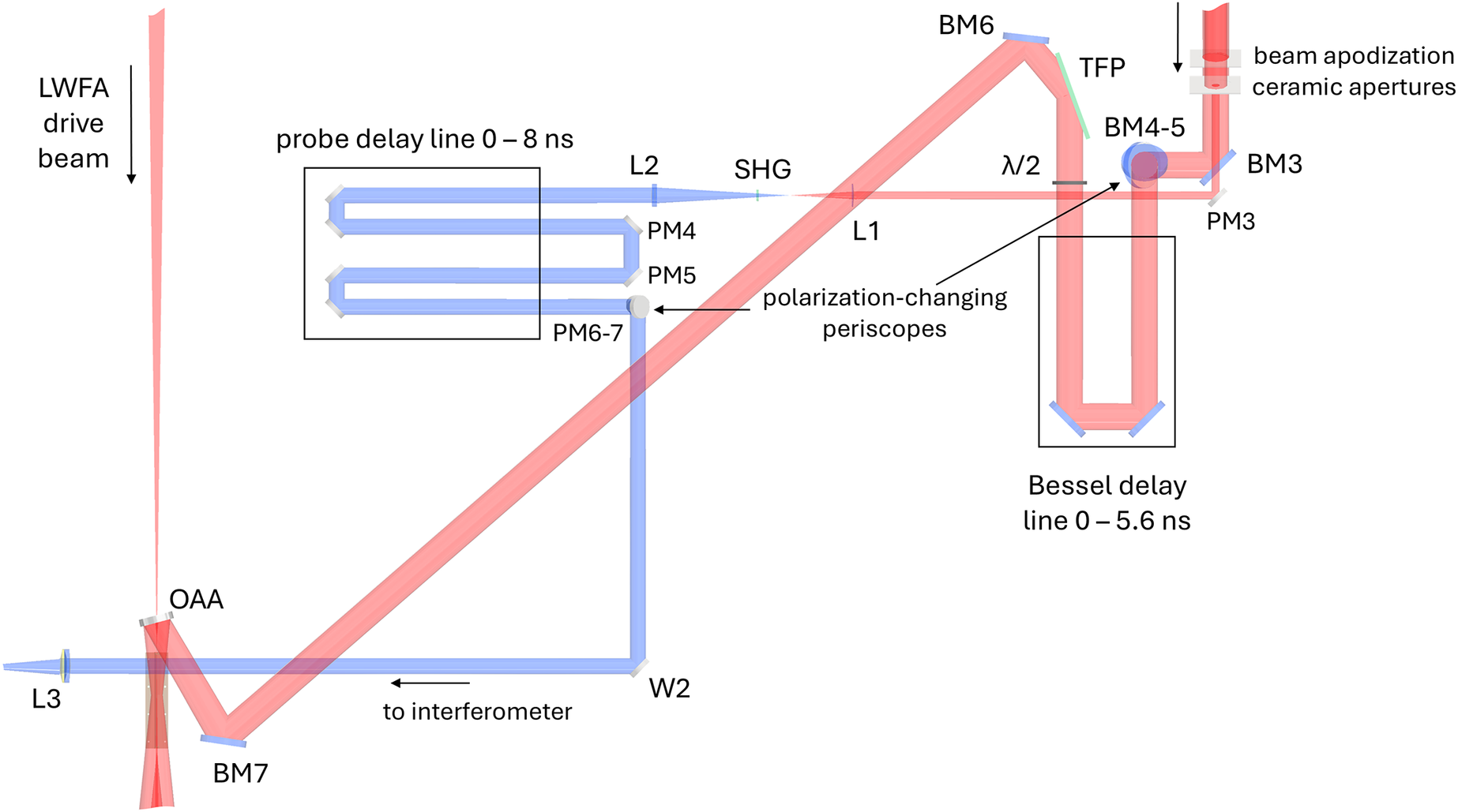

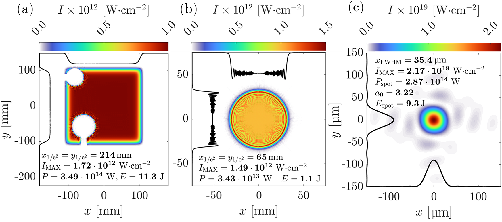
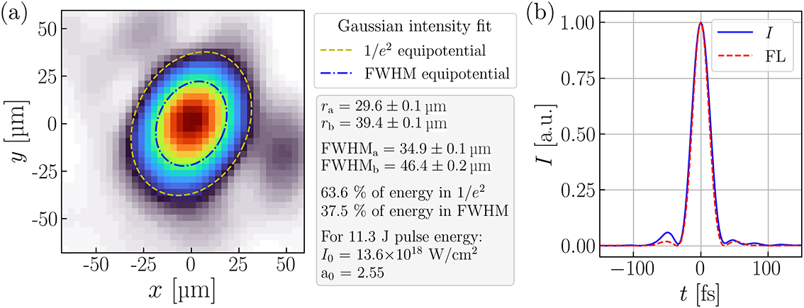


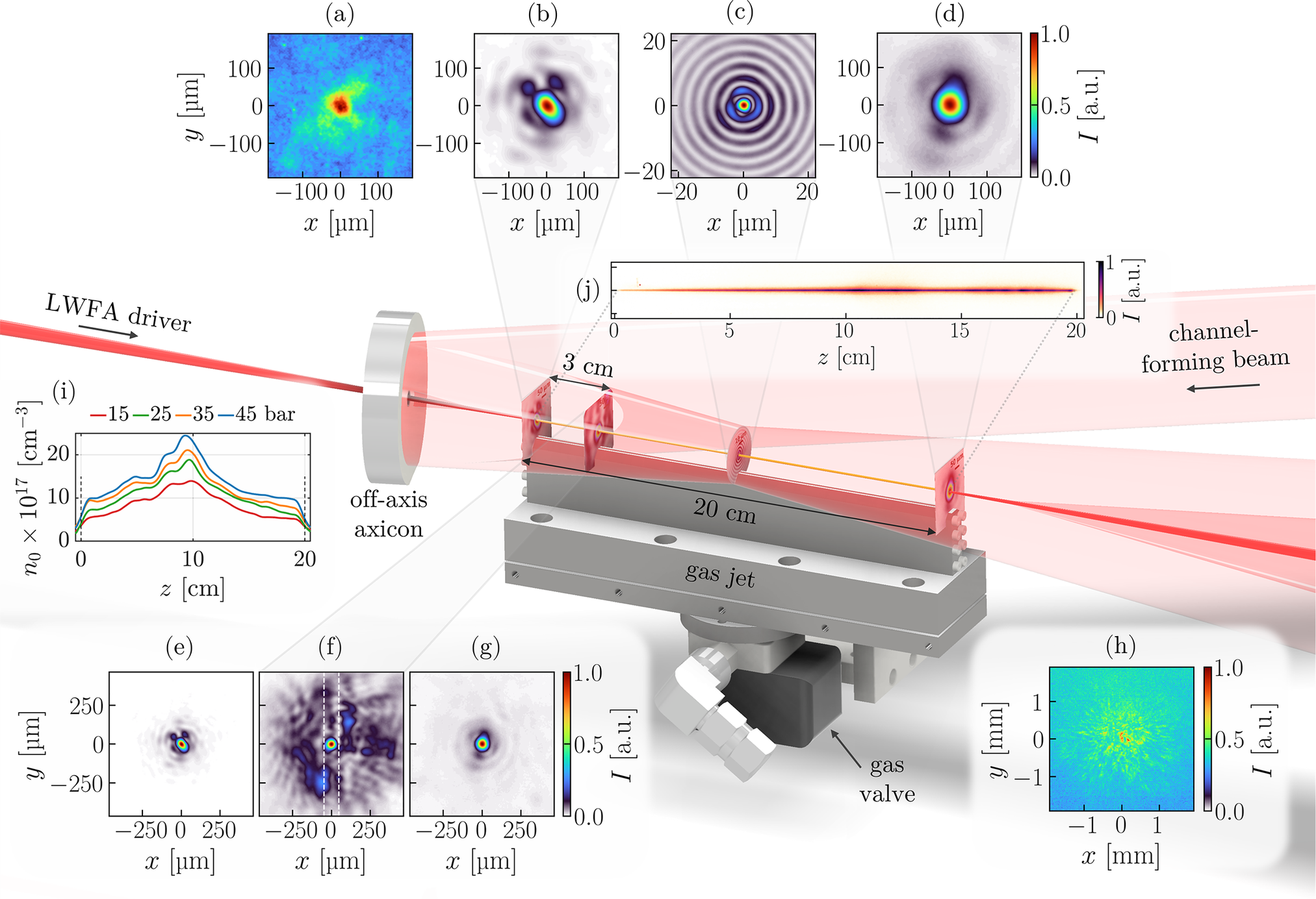


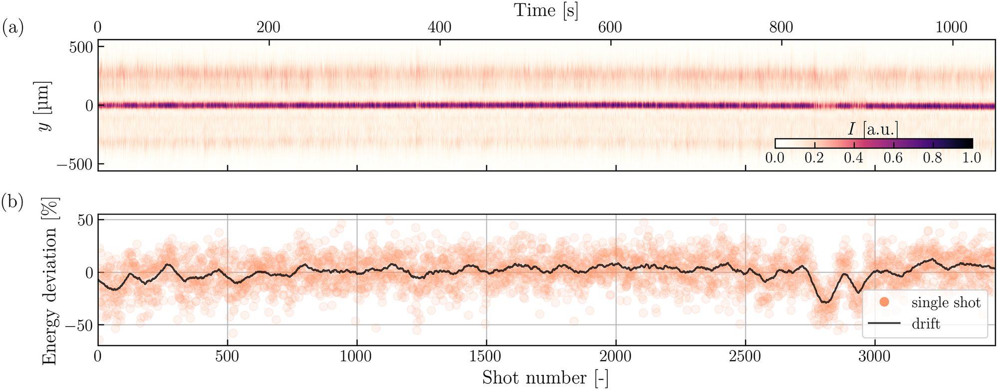

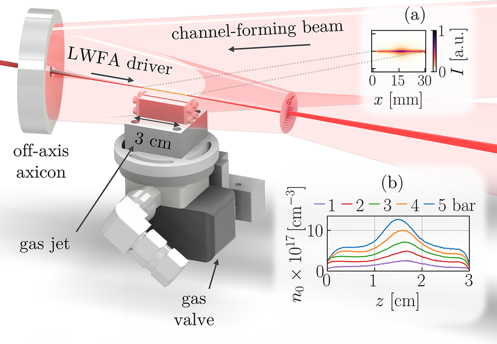
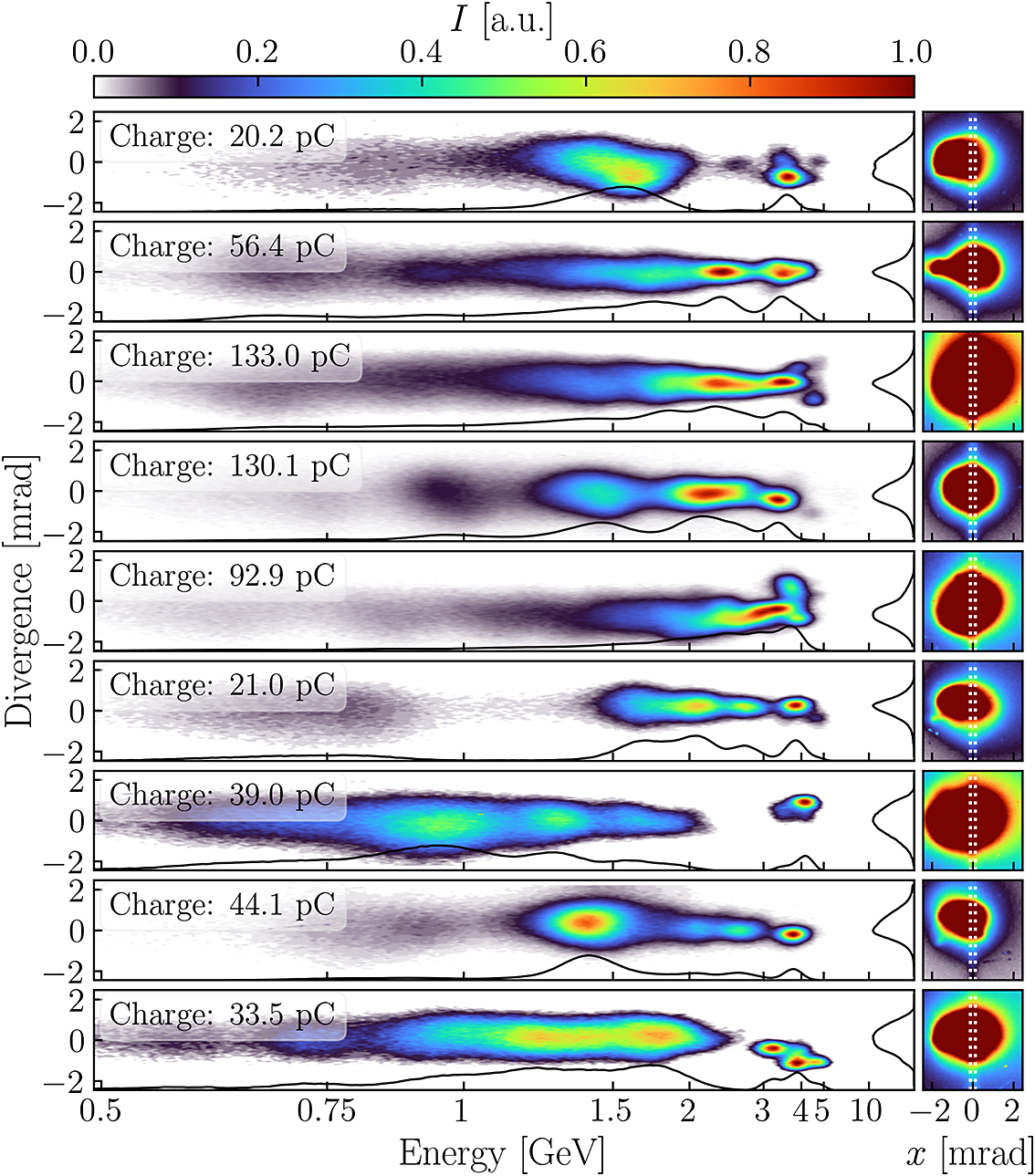
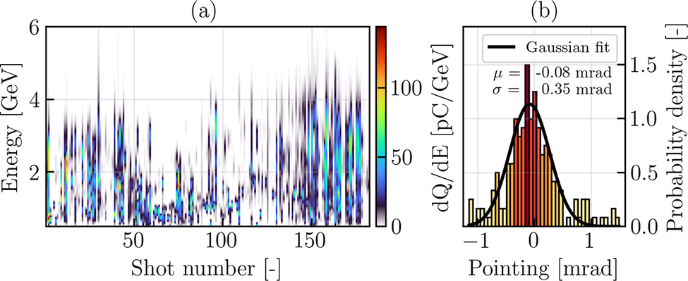

 Open access

