





1 Introduction
The rapid advancement of ultrafast science, exploring sub-femtosecond dynamics in physics, chemistry and biology, relies heavily on high-power, ultrashort laser systems[ Reference Krausz and Ivanov 1 , Reference Krausz 2 ]. Intense, few-cycle laser pulses enable the investigation of electron dynamics in atoms and molecules, including photoionization, collective electron effects[ Reference Smirnova, Mairesse, Patchkovskii, Dudovich, Villeneuve, Corkum and Ivanov 3 – Reference Nisoli, Decleva, Calegari, Palacios and Martín 5 ] and even nonlinear extreme ultraviolet (XUV) phenomena[ Reference Senfftleben, Kretschmar, Hoffmann, Sauppe, Tümmler, Will, Nagy, Vrakking, Rupp and Schütte 6 ]. These pulses are essential for driving high-harmonic generation (HHG), attosecond streaking and precision spectroscopy[ Reference Farkas and Tóth 7 – Reference Kretschmar, Hadjipittas, Major, Tümmler, Will, Nagy, Vrakking, Emmanouilidou and Schütte 13 ], with higher photon fluxes at increased repetition rates enabling shorter experiment durations and improved signal-to-noise ratios. Furthermore, carrier-envelope phase (CEP)-stabilized, few-cycle pulses have revolutionized time-resolved experiments, unveiling the dynamics of electrons, molecules and chemical bonds, and hence giving rise to the field of attosecond science[ Reference Xu, Hänsch, Spielmann, Poppe, Brabec and Krausz 14 – Reference Reinhard, Suraud and Meier 20 ].
Over the past decade, significant progress has been made in the development of CEP-stable, few-cycle laser systems. Technology based on optical parametric chirped-pulse amplification (OPCPA) has enabled the generation of more than 100 mJ, sub-two-cycle, CEP-stable pulses at 10 Hz with a central wavelength of 1.7 μm[ Reference Xu, Xue, Ishii, Itatani, Midorikawa and Takahashi 21 ], while at 1 kHz, the SYLOS 3 laser system at the Extreme Light Infrastructure Attosecond Light Pulse Source (ELI ALPS) has achieved 7.3 fs, 120 mJ pulses with less than 150 mrad CEP stability at a central wavelength of 830 nm[ Reference Tóth, Dey, Shirozhan, Mondal, Csontos, Geetha, Tóth, Somoskői, Dora, Kovalovszki, Abt, Kahaly and Börzsönyi 22 ]. In the regime of even higher repetition rates, a different technical approach, namely, the coherent combination of Yb-doped fiber amplifiers[ Reference Seise, Klenke, Limpert and Tünnermann 23 ], has pushed the generation of few-cycle pulses beyond the 100 W average power threshold, with CEP stabilization demonstrated in several systems[ Reference Shestaev, Hoff, Sayler, Klenke, Hädrich, Just, Eidam, Jójárt, Várallyay, Osvay, Paulus, Tünnermann and Limpert 24 ]. In 2021, the HR1 laser system achieved 107 W average power with a 5.8 fs pulse duration at a 100 kHz repetition rate, reaching a CEP stability of 360 mrad[ Reference Hädrich, Shestaev, Tschernajew, Stutzki, Walther, Just, Kienel, Seres, Jójárt, Bengery, Gilicze, Várallyay, Börzsönyi, Müller, Grebing, Klenke, Hoff, Paulus, Eidam and Limpert 25 ]. In 2024 a similar but higher-power system yielded 250 W average power with sub-8 fs pulses, also operating at 100 kHz[ Reference Grebing, Wunderlich, Tschernajew, Shestaev, Just, Hilbert, Kern, Heilmann, Kienel, Masood, Heuermann, Gaida, Herrfurth, Breitkopf, Eidam and Limpert 26 ]. Both laser systems use a two-stage multi-pass cell (MPC) compression scheme. The coherently combined amplifiers also allow the increase in the repetition rate further, enabling carrier-envelope offset (CEO) frequency stability at immense power levels. Notable results include a 132 W system operating at 250 MHz with 265 mrad CEP stability[ Reference Luo, Liu, Gu, Zhu, Deng, Zhou, Di, Xie and Li 27 ], and a 1 kW system at 80 MHz with 220 mrad stability[ Reference Shestaev, Hädrich, Walther, Eidam, Klenke, Seres, Bengery, Jójárt, Várallyay, Börzsönyi and Limpert 28 ], although both have longer pulse durations.
While many OPCPA systems can generate few-cycle pulses directly, their average power scaling is limited by the thermo-optical effects of the crystals, and effective conversion requires top-hat beams. In contrast, Yb-fiber amplification method is scalable to significantly higher average powers, and excellent Gaussian beam quality is inherently ensured by the fiber technology. However, Yb-doped fiber amplifiers always generate longer, typically sub-picosecond pulses, which require post-compression techniques[ Reference Nagy, Simon and Veisz 29 ] to reach few-cycle durations. Commonly used post-compression techniques are hollow-core fibers (HCFs)[ Reference Nagy, Kretschmar, Vrakking and Rouzée 30 ] and, increasingly, MPC[ Reference Viotti, Seidel, Escoto, Rajhans, Leemans, Hartl and Heyl 31 , Reference Hanna, Daniault, Guichard, Daher, Délen, Lopez-Martens and Georges 32 ] compressors. Typically, HCFs perform well up to moderate powers[ Reference Nagy, Hädrich, Simon, Blumenstein, Walther, Klas, Buldt, Stark, Breitkopf, Jójárt, Seres, Várallyay, Eidam and Limpert 33 ], but MPCs are even more tolerant of high average powers because of their better thermal management capabilities, making them an ideal candidate for post-compression with enormous average powers.
The ELI ALPS facility was established to push the boundaries of few-cycle, high-average-power laser technology[ Reference Charalambidis, Chikán, Cormier, Dombi, Fülöp, Janáky, Kahaly, Kalashnikov, Kamperidis, Kühn, Lepine, L’Huillier, Lopez-Martens, Mondal, Osvay, Óvári, Rudawski, Sansone, Tzallas, Várallyay and Varjú 34 – Reference Shirozhan, Mondal, Grósz, Nagyillés, Farkas, Nayak, Ahmed, Dey, De Marco, Nelissen, Kiss, Oldal, Csizmadia, Filus, De Marco, Madas, Kahaly, Charalambidis, Tzallas, Appi, Weissenbilder, Eng-Johnsson, L’Huillier, Diveki, Major, Varjú and Kahaly 36 ]. The original concept envisioned a family of high-repetition-rate (100 kHz) ultrafast light sources aimed at setting new performance benchmarks in this field[ Reference Niikura, Légaré, Hasbani, Bandrauk, Ivanov, Villeneuve and Corkum 16 , Reference Kühn, Dumergue, Kahaly, Mondal, Füle, Csizmadia, Farkas, Major, Várallyay, Calegari, Devetta, Frassetto, Månsson, Poletto, Stagira, Vozzi, Nisoli, Rudawski, Maclot, Campi, Wikmark, Arnold, Heyl, Johnsson, L’Huillier, Lopez-Martens, Haessler, Bocoum, Boehle, Vernier, Iaquaniello, Skantzakis, Papadakis, Kalpouzos, Tzallas, Lépine, Charalambidis, Varjú, Osvay and Sansone 35 , Reference Shirozhan, Mondal, Grósz, Nagyillés, Farkas, Nayak, Ahmed, Dey, De Marco, Nelissen, Kiss, Oldal, Csizmadia, Filus, De Marco, Madas, Kahaly, Charalambidis, Tzallas, Appi, Weissenbilder, Eng-Johnsson, L’Huillier, Diveki, Major, Varjú and Kahaly 36 ]. To maintain its leading-edge capabilities, our facility continuously advances its laser systems. This includes ongoing improvements to the HR1 system[ Reference Shestaev, Hoff, Sayler, Klenke, Hädrich, Just, Eidam, Jójárt, Várallyay, Osvay, Paulus, Tünnermann and Limpert 24 , Reference Hädrich, Shestaev, Tschernajew, Stutzki, Walther, Just, Kienel, Seres, Jójárt, Bengery, Gilicze, Várallyay, Börzsönyi, Müller, Grebing, Klenke, Hoff, Paulus, Eidam and Limpert 25 ] and, most recently, the development of HR2, which is the primary focus of this work. HR2 is designed to provide 500 W sub-two-cycle pulses[ Reference Haedrich, Walther, Kienel, Simon, Nagy, Blumenstein, Shestaev, Klas, Buldt, Stark, Breitkopf, Jójárt, Várallyay, Osvay, Eidam and Limpert 37 ], and although this power level has not yet been fully achieved, its progress is paramount. Furthermore, our system portfolio has been expanded with an auxiliary HR-Alignment system[ Reference Gilicze, Seres, Bengery, Bartyik, Csizmadia, Oldal, Nagymihály, Jójárt, Borzsonyi and Varallyay 38 ], featuring a tunable low repetition rate and pulse specifications identical to HR1. These systems typically utilize chirped-pulse amplification (CPA) followed by nonlinear compression MPCs[ Reference Grebing, Wunderlich, Tschernajew, Shestaev, Just, Hilbert, Kern, Heilmann, Kienel, Masood, Heuermann, Gaida, Herrfurth, Breitkopf, Eidam and Limpert 26 , Reference Schulte, Sartorius, Weitenberg, Vernaleken and Russbueldt 39 – Reference Müller, Buldt, Stark, Grebing and Limpert 42 ], and chirped mirrors, to generate ultrashort, high-energy pulses.
In this paper, we present a significant advancement in laser technology with the realization of a more than 400 W, sub-7 fs, CEP-stable laser system operating at 100 kHz. This achievement sets a new benchmark, representing the highest average power ever reported for a few-cycle laser system[ Reference Hädrich, Kienel, Müller, Klenke, Rothhardt, Klas, Gottschall, Eidam, Drozdy, Jójárt, Várallyay, Cormier, Osvay, Tünnermann and Limpert 43 ], with the further significance of realizing CEP stability. At this unprecedented power level, our system is the first to incorporate three MPC stages, demonstrating an approach to achieving such high power while maintaining excellent pulse and beam quality[ Reference Sobolev, Volkov, Svirplys, Thomas, Witting, Vrakking and Schütte 44 ]. This system, known as the HR2 laser system at the ELI ALPS facility, is currently undergoing commissioning and is poised to become a key driver for experiments in our target laboratories, working in conjunction with the HR1 laser. These high-average-power, high-repetition-rate lasers are primarily designed for time-resolved attosecond studies. Their main application is the generation of high-harmonics in gas (GHHG), which are then utilized in pump–probe schemes for advanced techniques such as spin- and energy-resolved photoemission microscopy (NanoESCA) and photo-dissociation coincidence spectroscopy (REMI)[ Reference Shirozhan, Mondal, Grósz, Nagyillés, Farkas, Nayak, Ahmed, Dey, De Marco, Nelissen, Kiss, Oldal, Csizmadia, Filus, De Marco, Madas, Kahaly, Charalambidis, Tzallas, Appi, Weissenbilder, Eng-Johnsson, L’Huillier, Diveki, Major, Varjú and Kahaly 36 , Reference Ye, Csizmadia, Oldal, Gopalakrishna, Füle, Filus, Nagyillés, Divéki, Grósz, Dumergue, Jójárt, Seres, Bengery, Zuba, Várallyay, Major, Frassetto, Devetta, Lucarelli, Lucchini, Moio, Stagira, Vozzi, Poletto, Nisoli, Charalambidis, Kahaly, Zaïr and Varjú 45 ].
2 System layout and results
A schematic of the entire laser system is illustrated in Figure 1. The pulse source of the laser system is a FLINT (Light Conversion FL1-01-NS, CEP) free-space oscillator[ 46 ] chosen to mitigate the excess phase noise typically found in fiber oscillators[ Reference Raabe, Feng, Mero, Tian, Song, Hänsel, Holzwarth, Sell, Zach and Steinmeyer 47 ]. It delivers approximately 50 fs full width at half maximum (FWHM) pulses at 60 MHz with an integrated phase noise of 140 mrad root mean square (RMS) (from 10 Hz to 30 MHz) at a central wavelength of 1035 nm. These pulses are then processed in the preamplifier box, which comprises two main parts: the seeder module and the ytterbium (Yb)-doped large-mode-area (LMA) fiber preamplifiers. The seeder module begins with tunable chirped fiber Bragg grating (CFBG)-based pulse stretchers, which can instantaneously elongate the pulses into the nanosecond regime, and provide options for wide-range active tuning of second-, third- and fourth-order dispersion coefficients. A spatial light modulator is also integrated into the stretcher to enable even more precise higher-order tuning of the spectral phase and amplitude by allowing them to be shaped according to an arbitrary function of wavelength within a defined range. This pulse-shaping capability is essential, for example, in compensating for residual nonlinear effects or mitigating gain narrowing in the main amplifiers. Stretching reduces the peak power of the chirped pulses, preventing significant self-phase modulation (SPM) during amplification in the subsequent LMA fiber amplifiers. Following these stretcher units, a pulse picker, implemented by a double acousto-optical modulator (AOM) configuration, reduces the repetition rate from 60 MHz to 100 kHz. Within the seeder module, optical isolators are integrated between the stages to protect the gain fibers and oscillator from back-reflections. Optical losses in the front-end are compensated by deeply saturated amplifiers – a condition we found critical for the CEP performance of the laser, as detailed below.
Schematic layout of the HR2 laser system, seeded by a FLINT oscillator. AOM, acousto-optic modulator; EOM, electro-optic modulator; CFBG, chirped fiber Bragg grating; LMA, large mode area; BPS, beam pointing stabilization; MPC, multi-pass cell; CEO, carrier-envelope offset; CEP, carrier-envelope phase.

The seeder module is followed by the first Yb-doped LMA fiber preamplifier, which increases the average power from the mW level to the W range. Beyond this first stage, the beam is split (50/50), feeding two additional, parallel Yb-doped LMA fiber preamplifier channels to boost the average power to approximately 2 × 10 W. The outputs of both preamplifiers are further split into eight equal parts, each directed into individual parallel Yb-doped LMA fiber amplifier channels, 16 in total. Each channel employs a backward-pumping scheme using continuous-wave nominal 250 W pump diodes. The Yb-doped fibers are 1 m long, with a mode-field diameter (MFD) of 65 μm and an inner cladding diameter of 260 μm for pump light coupling. These amplified beams are subsequently coherently combined[ Reference Klenke, Hädrich, Kienel, Eidam, Limpert and Tünnermann 48 , Reference Breitkopf, Hädrich, Kienel, Eidam, Shestaev, Jójárt, Varallyay, Osvay and Limpert 49 ]. To this end we monitor the polarization of the recombined beam after each combination stage, and use Hänsch–Couillaud detectors, as presented in Ref. [Reference Seise, Klenke, Limpert and Tünnermann23]. To maintain consistent polarization, which is crucial for efficient coherent combination, active path length stabilization is required. The precise phase adjustment between the channels is implemented using piezo-electric actuators. The detected polarization error signal is then fed back to piezo-controlled mirrors for real-time delay adjustments. Further details of the combination method can be found in Ref. [Reference Seise, Klenke, Limpert and Tünnermann23].
The 16-channel amplifier system proved to be able to deliver more than 1 kW average power after the grating compressor at 270 fs pulse duration[ Reference Hädrich, Shestaev, Tschernajew, Stutzki, Walther, Just, Kienel, Seres, Jójárt, Bengery, Gilicze, Várallyay, Börzsönyi, Müller, Grebing, Klenke, Hoff, Paulus, Eidam and Limpert 25 ]. However, the beam exiting the main amplifier was intentionally set to an output power of 535 W. This amount of power could be achieved with half of the amplifier channels and was already sufficient to reach the target nonlinearity in the first MPC. The extensive power reserve can be used for future needs, for example, further power scaling of the post-compression system. However, higher input powers would necessitate significant further development and geometrical modifications to all post-compression stages.
After the main amplifier, a free-space grating compressor reduces the pulse duration from the nanosecond regime to 270 fs. This compressor uses dielectric reflection gratings with a high average reflection efficiency of 99.3%. Effective thermal management is critical, as temperature variations can induce air convection, which can lead to pulse duration fluctuations, beam pointing instability and increased CEP noise. In addition to the water-cooled breadboard, which is used throughout the entire laser system, all parasitic reflections, including the zeroth-order reflections from the gratings, are directed into water-cooled beam dumps to further minimize thermal effects.
As mentioned in the introduction, Yb-fiber lasers require post-compression to reach few-cycle pulse durations. In the design and development phase, we considered both HCF and MPC techniques. Both methods have their own advantages and limitations. Regarding HCFs, the spatial output beam is almost always perfectly Gaussian, and its beam divergence remains nearly constant across a wide range of input powers. From a nonlinear perspective, the system can be easily down-scaled in pulse energy by increasing the gas pressure, even in the few-cycle regime. In addition, the possibility of differential pumping provides extra flexibility to suppress ionization. By comparison, MPC technology offers significantly higher transmission, and when properly seeded, it can also support a clean Gaussian output. Maintenance is typically easier. If damage occurs, usually only a mirror needs to be replaced. Moreover, since there is no solid surface near the focal region, the risk of optical damage is reduced, making the setup more robust against accidental input beam pointing fluctuations. A shared benefit of both methods is that, when properly implemented, they can produce radially homogeneous spectral broadening. Based on these considerations, as well as preliminary tests (which are outside the scope of this paper), but primarily due to the higher average power capabilities of MPC technology, we decided to implement that.
The aberration-compensated beam from the grating compressor is coupled into the first MPC (MPC1). This is filled with 950 mbar of argon (Ar) gas, and the beam undergoes multiple reflections, creating five focal spots within the 8-m-long cavity. These intense focal spots induce strong nonlinear interactions with the Ar atoms, broadening the spectrum via SPM from an initial 270 fs transform-limited pulse duration to a bandwidth supporting transform-limited pulse duration of 50 fs. After MPC1, the beam passes through a half-wave plate (HWP), a thin-film polarizer (TFP) and a telescope to increase the beam diameter and mitigate the risk of optical damage on the subsequent chirped mirrors. Pulse compression to approximately 51 fs is then achieved using 12 2-inch chirped mirrors, each providing –350 fs² of group delay dispersion (GDD). When the laser system is optimized for the final, sub-two-cycle operation, the power at this stage is 520 W. Before entering the second MPC stage (MPC2), another HWP ensures the beam maintains s-polarization. The output from MPC1 can be utilized independently in the so-called ‘long-pulse mode’ of the laser system, wherein the beam bypasses further post-compression stages. Instead, it is directed through a switching chamber to the final chamber of the laser, which is connected to the target area through a beam transport system, all under high vacuum. At this output, continuous power control with arbitrary linear polarization is realized via a combination of HWP + TFP + HWP optical components. In this long-pulse operation mode, the bandwidth can be further broadened in order to support below 37 fs Fourier transform limited (FTL) pulse duration either by replacing the gas in MPC1 with krypton (Kr) or by increasing the output power to 620 W – the maximum safe power handling capacity of the MPC1 optics. This power level was reached with all 16 amplifier channels activated in the main LMA amplifier. However, the obtained output from this operation mode in MPC1 could not be sustained using the subsequent MPCs.
In the short-pulse operation mode, after MPC1 the beam is directed through a telescope into MPC2, which contains five focal spots in a lower-pressure (250 mbar) Ar environment. This stage results in further spectral broadening, achieving a bandwidth sufficient to support a transform-limited pulse duration of sub-12 fs. The MPC2 configuration with five foci was found to yield superior beam caustics compared to the seven-pass MPC2 setup, which allowed for sub-9 fs pulse durations. Subsequent compression is accomplished with three pairs of complementary chirped mirrors, where each individual mirror provides –67 fs² of GDD and has a reflectivity better than 99.5% per bounce.
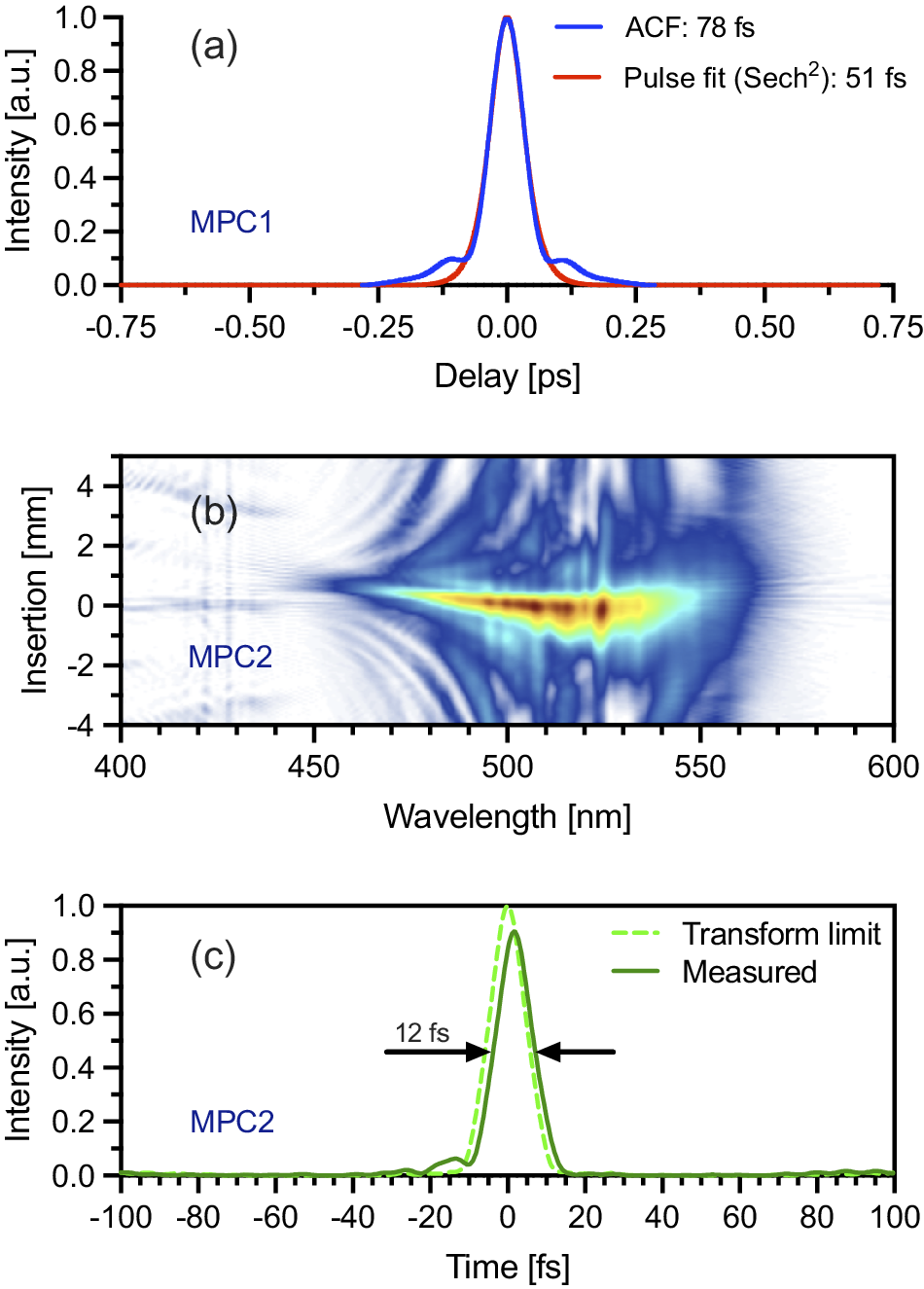
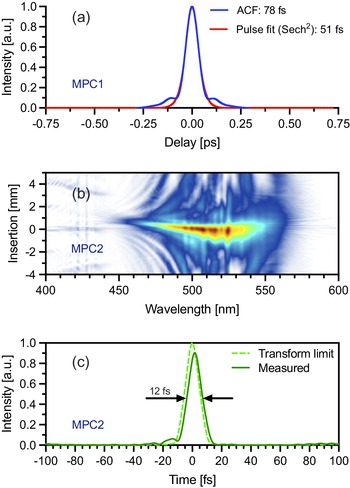
Optimizing MPC2 involved carefully adjusting the gas pressure and number of focal passes. The primary goal was to achieve the broadest possible spectrum while preserving the quality of the input beam’s caustics. We observed that an increase in the number of focal passes amplified residual astigmatism (the difference of divergence between the vertical and horizontal axes) from the input beam, and also accumulated imperfections from the cavity mirror surfaces. For high-power operation, we successfully optimized MPC2 to a maximum of five focal passes, which introduced no measurable additional astigmatism at its output. The optimal absolute pressure was determined to be 250 mbar of argon, resulting in a compressible pulse duration of sub-12 fs after this stage. Higher pressures led to excessive self-focusing, degrading both beam quality and pulse compressibility after nonlinear spectral broadening. Specifically, the beam profile tended toward a Lorentzian shape with a higher central peak power, increasing the risk of mirror damage. An alternative configuration with slightly less pressure and two additional focal passes (seven in total) yielded a somewhat degraded but still usable beam caustic, corresponding to a sub-9 fs compressible pulse. However, this was still insufficient to reach our sub-7 fs target for the final laser output. The underlying reason for the limited performance of MPC2 was rooted in beam astigmatism, which is discussed in detail later in this paper. The measured autocorrelation trace of the pulses exiting MPC1 in the final design, recorded with an APE pulseCheck autocorrelator, is shown in Figure 2(a), while the d-scan measurement of the MPC2 output, acquired with a Sphere Photonics device, is presented in Figure 2(b).
(a) Measured autocorrelation trace of the pulses after the MPC1 stage, (b) measured d-scan trace and (c) retrieved pulse shape of the MPC2 stage.
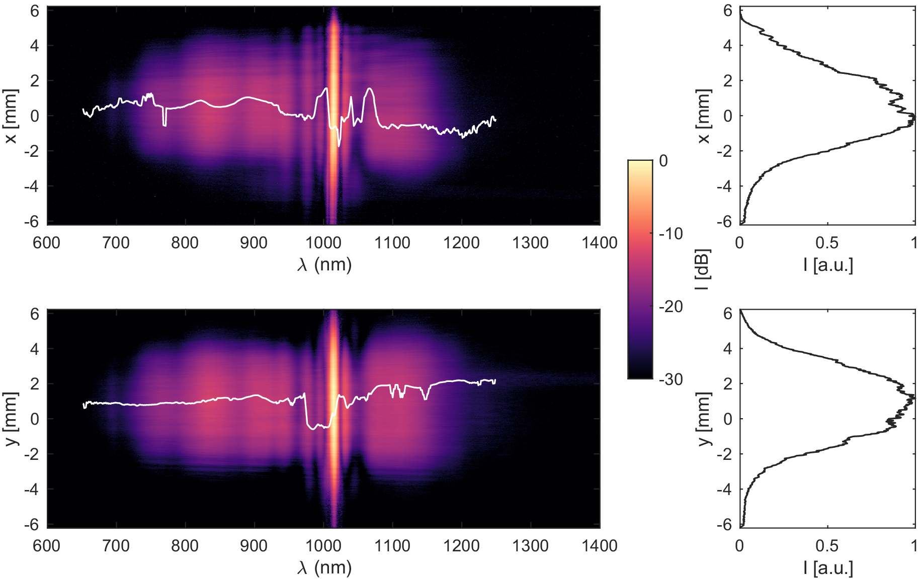
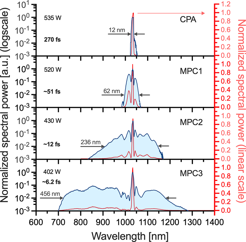
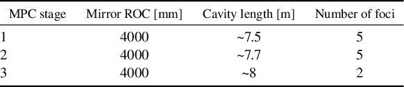
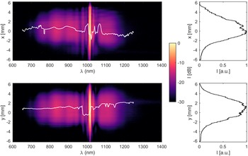
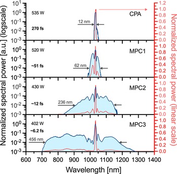
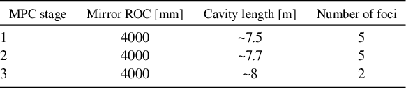
To reach the desired sub-7 fs pulse duration, we introduced a third broadening stage (MPC3) using helium (He) for more subtle nonlinear interactions. Helium’s exceptionally low nonlinear refractive index and high ionization threshold permit further spectral broadening at this intensity level without the ionization and excessive self-focusing encountered with other noble gases. MPC3 is filled with 1150 mbar of He, and the beam traverses two focal spots within the 8-m-long cell. Although the final optimized configuration utilizes only these two foci at 1150 mbar, the setup is designed as an MPC with the possibility of configurations with higher pass counts at lower gas pressures. The employed two-pass arrangement was, however, found to provide the optimal balance between spectral broadening and beam quality. In order to show the spatial homogeneity of the broadened spectrum, we measured the two-dimensional (2D) spectrogram of the beam using a FemtoEasy 2D MISS-YSWIR-1296-L1000-custom spectrometer. Figure 3 shows also that the spatial chirp in the x and y directions is negligible. The progressive spectral broadening and pulse characteristics achieved in each MPC stage are illustrated in Figure 4. Spectra for CPA and MPC1 were measured using an Ocean Insight STS-NIR spectrometer, while the spectrum for MPC2 was recorded with a Yokogawa AQ6373B (350–1200 nm) and that for MPC3 with the fundamental spectrometer of the Sphere Photonics d-scan. Our optimization of this three-stage MPC post-compression scheme revealed that aberration compensation is critical. For each MPC stage, the gas type and pressure were meticulously optimized to ensure stable, reproducible operation of the final, sub-two-cycle output. Additional parameters of the three MPC stages are collected in Table 1.
Measured 2D spectrum of the beam exiting MPC3, including the spatial chirp (solid white line).
Spectra after the CPA, MPC1, MPC2 and MPC3 (indicating the corresponding measured pulse durations). The corresponding spectra on a linear scale are plotted as solid red lines (right-hand y-axis).
Summary of MPC parameters: mirror radius of curvature (ROC), cavity length and number of foci for each stage.
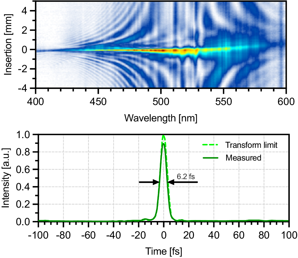
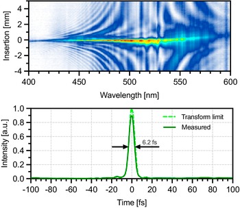
This final stage broadened the spectrum to 456 nm (at –20 dB relative to the peak), enabling the generation of stable and reproducible 6.2 fs pulses, with 402 W of average power, measured by a water-cooled Gentec power meter, placed after a Thorlabs BSF20 beam sampler and the output window of the chamber. The sampler reflected 14 W toward the diagnostic devices, while the diagnostics themselves require less than 4 W in total. These pulses were characterized using d-scan measurement, with the trace shown in Figure 5. The d-scan trace indicates a near-ideally compressed pulse after the MPC3 compression stage, implemented using a single pair of complementary chirped mirrors in the sampling beam, with –67 fs² GDD per reflection. These are the same type of chirped mirrors used for compressing the MPC2 pulses, exhibiting a reflectivity exceeding 99.5% per bounce. The d-scan software indicates that the peak power of the pulses is at least 90% of the transform-limited pulse calculated from the final spectrum. The beam path sampled for the d-scan also included a 3 mm fused silica output window and approximately 1.5 m of propagation through air.
The d-scan trace with the retrieved transform-limited and measured pulse shapes.
The cavity mirrors of MPC2 and MPC3 are free-standing silver mirrors selected to support the broad spectral bandwidth without introducing spectral phase ripples, except for one mirror placed after the first focus of MPC2, which is a semi-broadband dielectric mirror (930–1130 nm). These mirrors have monocrystalline silicon substrates, which are glued onto water-cooled beam blocks. This substrate has one of the highest thermal conductivities among non-metallic materials[ Reference Müller, Buldt, Stark, Grebing and Limpert 42 ], which is critical when an absorbing silver coating is exposed to several hundred watts of average power on a relatively small, few mm spot size. This ensures an evenly tempered mirror surface, despite the residual power absorption on a small beam spot, eliminating the possibility of heat lensing and beam distortion. In the event of coating damage, this substrate can absorb and dissipate several hundred watts of average power for several minutes before complete evaporation occurs. This resilience is due in part to its slight transparency in this spectral range, which allows the light to penetrate deeper into the material. As a result, the heat is distributed over a larger volume rather than being concentrated at the surface.
To mitigate slow thermal drifts and maintain optimal beam pointing and position, three active near- and far-field beam stabilization systems were implemented. These systems were strategically placed – the first before MPC1, the second before MPC2 and the third after MPC3 – to stabilize the final laser output. The placement of the first two systems was critical to ensure precise beam alignment into the MPCs, where pointing stability would be severely degraded by long propagation.
During the rather lengthy and rigorous process of MPC optimization in a high-order parameter space, we realized that beam astigmatism plays an even more critical and dynamic role than expected based on our previous experience with shorter MPCs. Despite this aberration-compensated design of the grating compressor, minor imperfections in the grating surfaces still introduced a slight residual astigmatism (approximately 1.2% in the ratio of the distance of the focal spots), which usually is assumed to be negligible in most everyday cases. However, this seemingly small residual astigmatism in this very long focal length arrangement becomes critical when interfacing with the subsequent 8-m-long MPC stages for nonlinear compression. We observed that any pre-existing astigmatism significantly builds up within these long MPCs, leading to a highly astigmatic and elliptical beam profile at their output. This enlargement occurs because the high-intensity beam near the focal spots within the MPCs interacts differently with the gas medium in the two orthogonal planes due to the intensity-dependent Kerr effect, causing differential self-focusing.
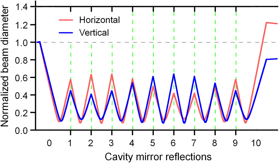
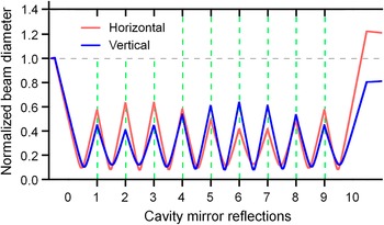
If a beam with astigmatism or ellipticity enters an MPC, these parameters will evolve continuously with each round trip, even in the absence of nonlinear effects. As illustrated with Gaussian beam propagation in Figure 6, beam diameter deviations – and even their signs – can vary after each round trip. Therefore, measuring these parameters at positions along the MPC somewhere beyond the first focus may lead to inaccurate conclusions and be deceiving regarding the required compensation. The degradation of the output beam profile is not the only drawback of astigmatism in MPCs. Another major concern is the increased near-field peak intensity resulting from the elliptical beam shape, which can lead to the damage of the cavity mirror coatings. As shown in Figure 6, the beam can become more elliptical at various reflection points. When nonlinear effects (omitted from the figure) are introduced, we experimentally observed that this oval beam shape can become even more pronounced at later reflections within the MPC, increasing further the risk of damage to the cavity mirrors. However, this pronounced sensitivity was not observed in our 2-m MPCs in the HR1 system[ Reference Hädrich, Shestaev, Tschernajew, Stutzki, Walther, Just, Kienel, Seres, Jójárt, Bengery, Gilicze, Várallyay, Börzsönyi, Müller, Grebing, Klenke, Hoff, Paulus, Eidam and Limpert 25 ], most likely because the propagation distance over which an astigmatic, oval-shaped beam experiences these differential effects before and after each focus is substantially greater in the longer, loosely focused MPCs.
The evolution of astigmatism in MPCs without nonlinear effects using Gaussian beams. Note that in the non-astigmatic case, red and blue curves should overlap and all peaks should have the same height.
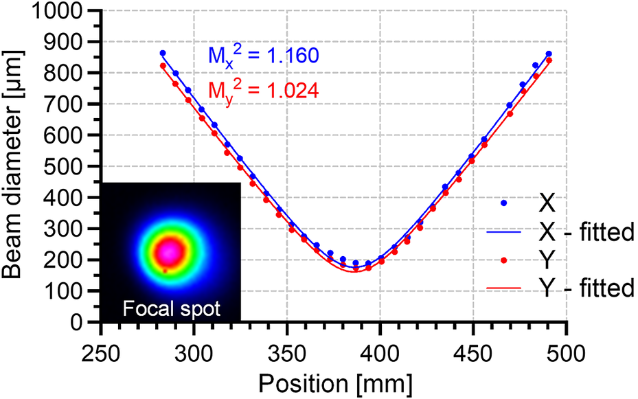
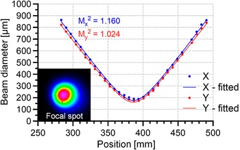
The beam quality of the sampled compressed beam of MPC3 was characterized using a Gentec BEAMAGE-M² measurement system. The laser beam, with a 15.3 mm 1/e² diameter, was focused using a lens with a focal length of f = 1.5 m after passing through beam samplers for attenuation. The measured beam caustic, presented in Figure 7, shows M² factors of 1.160 along the horizontal (x) axis and 1.024 along the vertical (y) axis, with a minimal astigmatism of 0.035%. Separately, we measured the wavefront using an Imagine Optic HASO sensor. The sensor was placed 40 cm before the focal point of the same f = 1.5 m lens. This wavefront measurement yielded a spatial Strehl ratio of 0.962. The chromatic aberration of the lens was neglected in these measurements, as repeating the experiments with approximately 50 nm bandpass color filters yielded only slightly improved results compared to those obtained with the full spectral bandwidth. Therefore, the presented measurements using the full bandwidth can be considered underestimated results. If we assume spatiotemporal couplings to be negligible and utilize the previously mentioned d-scan results, the effective spatial and temporal Strehl ratio is 0.87.
Results of the M 2 measurement along with the output beam profile in the focus.
With sub-two-cycle pulse durations the CEP stability can be measured using a Stereo-ATI pulse meter acquired from Single-Cycle Instruments[ Reference Wittmann, Horvath, Helml, Schätzel, Gu, Cavalieri, Paulus and Kienberger 50 , Reference Sayler, Rathje, Müller, Rühle, Kienberger and Paulus 51 ]. This device allows for single-shot measurement of the absolute CEP of individual pulses at a repetition rate of 100 kHz. By generating an error signal from the deviations in measured CEP values, it is possible to implement an active feedback loop that stabilizes the CEP to a defined phase setpoint.
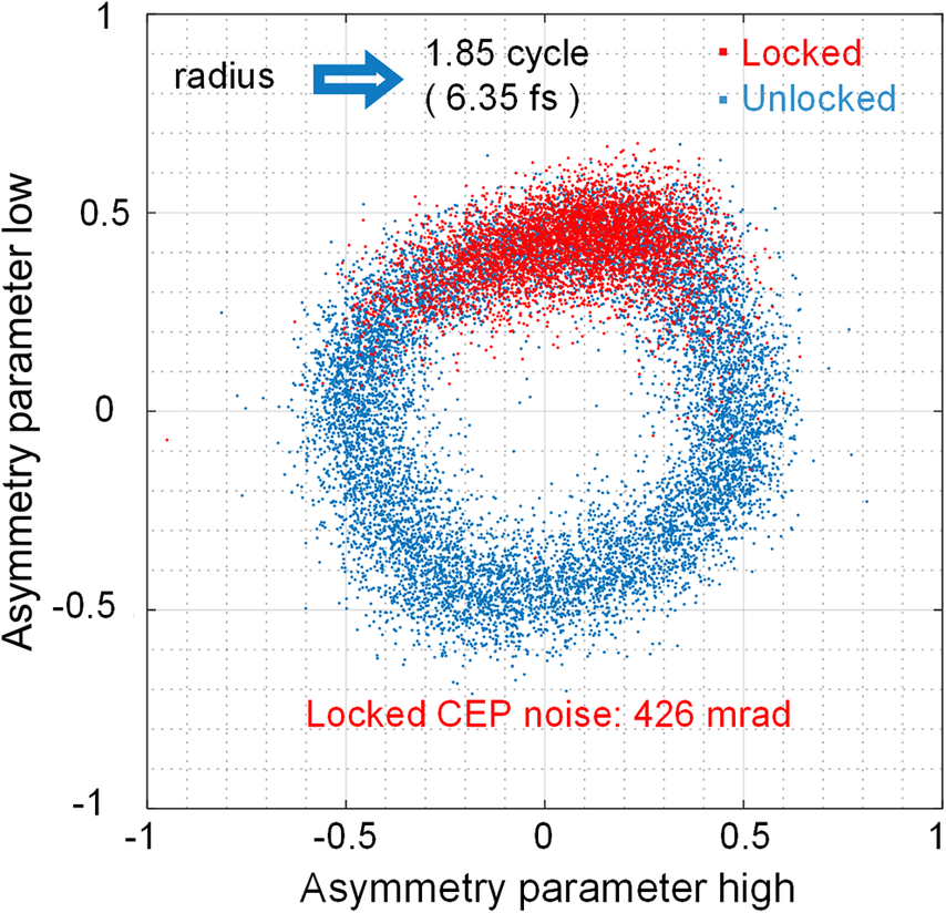
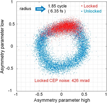
A sample of a long-term CEP stability measurement, with active locking, is shown in Figure 8 (red trace), with in-loop CEP noise of 426 mrad RMS, calculated as the standard deviation of all 105 shots over a 1 s sample. After optimization, the device required only 25 μJ of pulse energy from the sampling beam (originally 140 μJ, 14 W), further indicating that a high-quality short pulse was delivered to the Stereo-ATI device. In principle, the same pulses applied in the beamline would allow even for in-line diagnostics. The Stereo-ATI data are visualized in a polar diagram in which each dot represents a single laser pulse, characterized by its asymmetry radius, reflecting the pulse duration (the larger the shorter)[ Reference Sayler, Rathje, Müller, Kürbis, Rühle, Stibenz and Paulus 52 ], while the angular coordinate indicates the CEP. We measured the pulse duration of approximately 1.85 cycles (6.35 fs) by the Stereo-ATI data, which compared well to the 6.2 fs duration obtained from the d-scan at the MPC3 output, that is, the measurement accuracies of the two entirely different techniques agreed well. We implemented a CEP feedback loop, which combines the Stereo-ATI error signal directly with the intrinsic error signal of the oscillator. The CEP setpoint can be chosen between 0 and 2π. Furthermore, the Stereo-ATI system also offers real-time, single-shot CEP tagging, even without the feedback loop engaged. Future efforts will focus on improving this CEP stability by reducing front-end high-frequency noise and optimizing further the feedback control system.
Parametric asymmetry plot from the Stereo-ATI device, where red and blue dots show locked and unlocked CEP stability, respectively. Dots encode the CEP in the angle and the reciprocal pulse duration in the radius for individual laser pulses.
The shot-to-shot energy stability was also measured in the Stereo-ATI beam path by a Thorlabs DET025A/M Si photodiode and a Rohde-Schwarz RTO2004 oscilloscope. The maximum of the signal was 798 mV, and the standard deviation of this maximum was 645 μV for 104 shots, corresponding to a ±0.08% energy stability.
3 Conclusion
In conclusion, we have demonstrated a record-breaking, CEP-stable laser system delivering 6.2 fs pulses with an average power of 402 W at 100 kHz repetition rate. This unprecedented performance was achieved through a novel three-stage MPC compression scheme, following a kW-level, CEP-stable Yb-doped fiber CPA system. Also, meticulous compensation of astigmatism throughout the entire system was crucial for achieving optimal beam quality (Strehl ratio > 0.87) and pulse compression in the MPC stages. The achieved CEP stability is better than 426 mrad RMS measured up to the Nyquist frequency (10 Hz–50 kHz), enabling advanced applications in ultrafast science and attosecond pulse generation. This work establishes a new benchmark for high-power, sub-two-cycle, CEP-stable laser systems and represents a significant advancement for high-field physics research at facilities such as ELI ALPS.
Acknowledgements
The authors are grateful to Steffen Hädrich for his immeasurable contributions to the HR2 laser project during its early years at Active Fiber Systems. They are particularly thankful to Tamás Nagy and Péter Simon for their extensive scientific developments related to post-compression, which supported the final implementation. The authors express their appreciation to Károly Osvay and Gábor Szabó for their valuable engagement in the scientific project management of the laser at the ELI ALPS facility. They also extend their thanks to Roland Nagymihály for his scientific advices on the manuscript, especially regarding the two-dimensional spectral characterization of the output. Furthermore, they acknowledge the dedicated support of the ELI ALPS engineering, vacuum technological and technical staff, including Bernát Vinkó, Árpád Mohácsi, Arnold P. Farkas, Krisztián Kasza and Zoltán Vajna.
The ELI ALPS project (GINOP-2.3.6-15-2015-00001) is supported by the European Union and co-financed by the European Regional Development Fund.


 Open access

