





1. Introduction
Internal gravity waves propagating within stably stratified fluids are ubiquitous in geophysical and astrophysical systems. Through the transport of mass, momentum and energy, they play a central role in shaping oceanic and atmospheric circulations (Andrews, Holton & Leovy Reference Andrews, Holton and Leovy1987; Bühler Reference Bühler2014; Vallis Reference Vallis2017; Whalen et al. Reference Whalen, de Lavergne, Naveira Garabato, Klymak, MacKinnon and Sheen2020; Le Bars Reference Le Bars2023), and influence the internal dynamics of stars (Rogers et al. Reference Rogers, Lin, McElwaine and Lau2013). Recent studies have highlighted the significant impact of diapycnal mixing driven by internal gravity waves on a range of climate phenomena. However, accurately resolving the short vertical scales associated with these processes, particularly in climate simulations, remains challenging, underscoring the need for further theoretical modelling and systematic study of internal gravity wave dynamics (MacKinnon et al. Reference MacKinnon2017).
For strongly dispersive waves at sufficiently small amplitudes, weak wave turbulence theory provides a systematic framework for deriving a closed kinetic equation governing the slow evolution of the ensemble-averaged spectral energy density (Hasselmann Reference Hasselmann1966; Zakharov, L’vov & Falkovich Reference Zakharov, L’vov and Falkovich1992; Nazarenko Reference Nazarenko2011; Newell & Rumpf Reference Newell and Rumpf2011; Galtier Reference Galtier2022). The first kinetic equation describing nonlinear interactions of three-dimensional internal waves in the presence of rotation was derived by Olbers (Reference Olbers1976). Since then, the theory has been revisited using a variety of formalisms and assumptions (see, e.g. Pelinovsky & Raevsky Reference Pelinovsky and Raevsky1977; Müller et al. Reference Müller, Holloway, Henyey and Pomphrey1986; Caillol & Zeitlin Reference Caillol and Zeitlin2000; Lvov & Tabak Reference Lvov and Tabak2001, Reference Lvov and Tabak2004; Lvov, Polzin & Yokoyama Reference Lvov, Polzin and Yokoyama2012; Labarre et al. Reference Labarre, Lanchon, Cortet, Krstulovic and Nazarenko2024b ; Scott & Cambon Reference Scott and Cambon2024).
In the absence of rotation, and under the hydrostatic approximation – appropriate for motions with horizontal scales much larger than vertical scales – formal steady solutions of the kinetic equation have been obtained (Pelinovsky & Raevsky Reference Pelinovsky and Raevsky1977; Caillol & Zeitlin Reference Caillol and Zeitlin2000; Lvov & Tabak Reference Lvov and Tabak2001). However, these solutions were later shown not to be physically realisable due to divergences in the collision integral (Caillol & Zeitlin Reference Caillol and Zeitlin2000). Subsequent studies identified a unique bi-homogeneous steady spectrum yielding a convergent collision integral (Lvov et al. Reference Lvov, Polzin, Tabak and Yokoyama2010; Dematteis & Lvov Reference Dematteis and Lvov2021); however, this three-dimensional prediction has not been observed in numerical simulations. More recently, within the hydrostatic limit, Lanchon & Cortet (Reference Lanchon and Cortet2023) obtained steady solutions of a diffusion approximation to the kinetic equation that retains only induced-diffusion triadic interactions (McComas & Bretherton Reference McComas and Bretherton1977).
It is important to note that the kinetic equation is not expected to hold in the vicinity of slow modes, where key assumptions underlying its derivation – such as Gaussian statistics and scale separation – break down (Galtier Reference Galtier2022). In particular, the accumulation of energy near zero vertical wavenumber leads to divergences in the collision integral unless a regularisation is introduced. A physical regularisation can be interpreted as considering the rotating–stratified Boussinesq equations in the limit of very small but finite rotation compared with stratification (Shavit, Bühler & Shatah Reference Shavit, Bühler and Shatah2026).
In two dimensions, using this approach, Shavit et al. (Reference Shavit, Bühler and Shatah2025, Reference Shavit, Bühler and Shatah2026) found a steady solution of the full kinetic equation without invoking the hydrostatic approximation. The resulting turbulent energy spectrum is
 \begin{equation} e(\boldsymbol{k}) \propto k^{-3} \omega _{\boldsymbol{k}}^{-2}, \end{equation}
where $\boldsymbol{k} = (k_x,k_z)$
is the wave vector,
$\boldsymbol{k} = (k_x,k_z)$
is the wave vector, $k = \sqrt {k_x^2+k_z^2}$
its modulus,
$k = \sqrt {k_x^2+k_z^2}$
its modulus, $\omega _{\boldsymbol{k}} = N k_x/k$
the internal gravity wave frequency and
$\omega _{\boldsymbol{k}} = N k_x/k$
the internal gravity wave frequency and $N$
is the buoyancy (Brunt–Väisälä) frequency. Namely,
$N$
is the buoyancy (Brunt–Väisälä) frequency. Namely, $N=\sqrt {-( {g}/{\rho _0}) ( {\mathrm{d} \bar {\rho }}/{\mathrm{d} z})}$
, where
$N=\sqrt {-( {g}/{\rho _0}) ( {\mathrm{d} \bar {\rho }}/{\mathrm{d} z})}$
, where $g$
is the acceleration due to gravity,
$g$
is the acceleration due to gravity, $\rho _0$
is the reference density and
$\rho _0$
is the reference density and $\bar {\rho }(z)$
the average density. Here,
$\bar {\rho }(z)$
the average density. Here, $N$
quantifies the stratification of the fluid and usually depends on the elevation. Yet, it is common to assume that
$N$
quantifies the stratification of the fluid and usually depends on the elevation. Yet, it is common to assume that $N$
is constant where the average density profile
$N$
is constant where the average density profile $\bar {\rho }(z)$
is nearly linear, as done by Shavit, Bühler & Shatah (Reference Shavit, Bühler and Shatah2025). Expressed in frequency–vertical-wavenumber coordinates
$\bar {\rho }(z)$
is nearly linear, as done by Shavit, Bühler & Shatah (Reference Shavit, Bühler and Shatah2025). Expressed in frequency–vertical-wavenumber coordinates $(\omega _{\boldsymbol{k}},k_z)$
, the spectrum (1.1) coincides with the Garrett–Munk (GM) spectrum (Garrett & Munk Reference Garrett and Munk1979) in the limit of zero rotation and short vertical scales compared with the domain depth,
$(\omega _{\boldsymbol{k}},k_z)$
, the spectrum (1.1) coincides with the Garrett–Munk (GM) spectrum (Garrett & Munk Reference Garrett and Munk1979) in the limit of zero rotation and short vertical scales compared with the domain depth,
 \begin{equation} k^{-3}\omega _{\boldsymbol{k}}^{-2}\,\mathrm{d} k_x\, \mathrm{d} k_z = k_z^{-2}\omega _{\boldsymbol{k}}^{-2}\frac {1}{N}\,\mathrm{d} k_z\, \mathrm{d}\omega _{\boldsymbol{k}} \propto e_{\mathrm{GM}}. \end{equation}
Despite known deviations between measured oceanic spectra and the idealised GM form, the GM spectrum remains a useful reference for describing internal gravity wave statistics (Polzin et al. Reference Polzin, Garabato, Alberto, Huussen, Sloyan and Waterman2014; Dematteis et al. Reference Dematteis, Le Boyer, Pollmann, Polzin, Alford, Whalen and Lvov2024).
Similar to other anisotropic dispersive waves in fluids, such as Rossby and inertial waves, internal gravity waves interact with slow modes, specifically domain, vortical and shear modes (Smith & Waleffe Reference Smith and Waleffe2002; Laval, McWilliams & Dubrulle Reference Laval, McWilliams and Dubrulle2003; Brethouwer et al. Reference Brethouwer, Billant, Lindborg and Chomaz2007; Waite Reference Waite2011; Remmel, Sukhatme & Smith Reference Remmel, Sukhatme and Smith2014; Howland, Taylor & Caulfield Reference Howland, Taylor and Caulfield2020; Rodda et al. Reference Rodda, Savaro, Davis, Reneuve, Augier, Sommeria, Valran, Viboud and Mordant2022). These slow modes present a significant challenge for the current weak wave turbulence description, which does not account for their evolution or interaction with dispersive waves. Their prominence in the energy spectrum complicates the observation of weak wave turbulence in internal gravity waves, both in direct numerical simulations (Remmel et al. Reference Remmel, Sukhatme and Smith2014) and experiments (Lanchon et al. Reference Lanchon, Mora, Monsalve and Cortet2023). In particular, a well-observed feature of stratified turbulence is layering (see Caulfield Reference Caulfield2021 and references therein), corresponding to an accumulation of energy in horizontal motions (shear and vortical modes) with the formation of well-mixed layers separated by sharp interfaces. If turbulence and stratification are strong enough, the layers’ thickness is ‘chosen’ by the flow such that $L_z = U_{\textit{rms}}/N$
, where
$L_z = U_{\textit{rms}}/N$
, where $U_{\textit{rms}}$
is the root mean square (r.m.s.) velocity of the large scale flow (Billant & Chomaz Reference Billant and Chomaz2001; Brethouwer et al. Reference Brethouwer, Billant, Lindborg and Chomaz2007). This phenomenon looks like a self-organised criticality, where the flow organises itself such that the Richardson number is close to a critical value (Caulfield Reference Caulfield2021), not far from the linear stability threshold (Howard Reference Howard1961; Miles Reference Miles1961).
$U_{\textit{rms}}$
is the root mean square (r.m.s.) velocity of the large scale flow (Billant & Chomaz Reference Billant and Chomaz2001; Brethouwer et al. Reference Brethouwer, Billant, Lindborg and Chomaz2007). This phenomenon looks like a self-organised criticality, where the flow organises itself such that the Richardson number is close to a critical value (Caulfield Reference Caulfield2021), not far from the linear stability threshold (Howard Reference Howard1961; Miles Reference Miles1961).
Several mechanisms have been proposed to explain layer formation in strongly stratified turbulence. Early models based on the evolution of the mean density profile demonstrated that small perturbations to an initially linear stratification can grow when buoyancy fluxes decrease with increasing Richardson number (Phillips Reference Phillips1972). Reduced-order models incorporating turbulent kinetic energy and buoyancy evolution further clarified the conditions for layering (Balmforth et al. Reference Balmforth, Smith, Stefan and Young1998; Taylor & Zhou Reference Taylor and Zhou2017; Petropoulos, Mashayek & Caulfield Reference Petropoulos, Mashayek and Caulfield2023). From a dynamical standpoint, vortical modes are known to undergo zigzag instabilities that produce layers at the scale $U/N$
(Billant & Chomaz Reference Billant and Chomaz2000a
,
Reference Billant and Chomazb
). Notably, however, layering has also been observed in two-dimensional simulations (Smith Reference Smith2001), in three-dimensional flows without vortical modes (Remmel et al. Reference Remmel, Sukhatme and Smith2014), and even in systems where both vortical and shear modes are removed (Calpe Linares Reference Calpe Linares2020; Labarre et al. Reference Labarre, Augier, Krstulovic and Nazarenko2024a
). These observations suggest that layering can arise from wave dynamics alone, motivating the search for a wave-turbulence-based explanation.
$U/N$
(Billant & Chomaz Reference Billant and Chomaz2000a
,
Reference Billant and Chomazb
). Notably, however, layering has also been observed in two-dimensional simulations (Smith Reference Smith2001), in three-dimensional flows without vortical modes (Remmel et al. Reference Remmel, Sukhatme and Smith2014), and even in systems where both vortical and shear modes are removed (Calpe Linares Reference Calpe Linares2020; Labarre et al. Reference Labarre, Augier, Krstulovic and Nazarenko2024a
). These observations suggest that layering can arise from wave dynamics alone, motivating the search for a wave-turbulence-based explanation.
In this work, we distinguish three regimes of two-dimensional stratified turbulence – discrete wave turbulence, weak wave turbulence and strong nonlinear interaction – within the parameter space defined by the Froude and Reynolds numbers. Using direct numerical simulation (DNS) of the Boussinesq equations with shear modes removed and employing hyperviscosity, we identify the conditions under which weak wave turbulence can be observed and provide the first DNS-based confirmation of the kinetic-theory prediction for internal gravity waves. Beyond the weakly nonlinear regime, we show that energy accumulation at slow frequencies leads to layer formation and derive scaling predictions for the resulting layer thickness and characteristic velocities in terms of the control parameters.
We remove shear modes to isolate dispersive wave interactions, reach statistically steady states efficiently and make direct comparisons with weak wave turbulence theory. The focus on two-dimensional flows is motivated by both practical and theoretical considerations. From a practical standpoint, two-dimensional (2-D) simulations are significantly less expensive than their three-dimensional (3-D) counterparts, allowing for extensive exploration of parameter space. From a theoretical perspective, the kinetic equation in 2-D (Shavit, Bühler & Shatah Reference Shavit, Bühler and Shatah2024) takes a simpler form due to the presence of an additional invariant and admits a theoretical prediction for the turbulent spectrum without invoking the hydrostatic approximation. While two-dimensional stratified flows do not capture interactions between gravity waves and vortical modes – present in three dimensions and crucial for vertical overturning and mixing – 2-D models nevertheless capture essential aspects of stratified dynamics and often serve as a first step towards understanding the full three-dimensional problem (Smith Reference Smith2001; Boffetta et al. Reference Boffetta, De Lillo, Mazzino and Musacchio2011; Fitzgerald & Farrell Reference Fitzgerald and Farrell2018; Calpe Linares Reference Calpe Linares2020). Moreover, a two-dimensional description is directly relevant for laboratory experiments in long water tanks and for certain oceanic settings, such as internal tides radiated from isolated one-dimensional topographic features like the Hawaiian Ridge (Smith & Young Reference Smith and Young2003). In the weak wave turbulence regime, excluding low frequencies, our simulations show good agreement with recent theoretical predictions (Shavit et al. Reference Shavit, Bühler and Shatah2025). As layering develops and spectral peaks emerge at slow frequencies, our results highlight the limitations of the kinetic approach, while simultaneously providing a simple, physically grounded explanation for layer formation, including scaling laws for the characteristic velocity $U$
and layer thickness
$U$
and layer thickness $L_z$
beyond the weakly nonlinear regime.
$L_z$
beyond the weakly nonlinear regime.
The remainder of the paper is organised as follows. In § 2, we introduce the governing equations and notation. In § 3, we identify the three turbulence regimes using wave-turbulence arguments. It emphasises that to observe the weak wave turbulence regime in a stratified fluid, a directed study must be done, which is crucial for experiments and future numerical investigations. The numerical set-up is described in § 4, and the results are analysed in § 5. We examine vorticity fields in § 5.1, one-dimensional spectra in § 5.2, and two-dimensional spectra and fluxes in § 5.3. A wave-turbulence-based interpretation of layer formation is presented in § 5.4, followed by a detailed comparison with theoretical predictions in § 5.5 and an analysis of Doppler shifts in § 5.6. Conclusions and perspectives are given in § 6.
2. Governing equations
2.1. Dynamical equations
Stratified flows can be described most simply using the Boussinesq equations, derived from the Euler equations by assuming a linear density profile in the vertical direction. For two-dimensional flows restricted to the vertical $xz$
plane, the Boussinesq equations are
$xz$
plane, the Boussinesq equations are
 \begin{align} {\boldsymbol{\nabla }} \boldsymbol{\cdot }{\boldsymbol{u}} &= 0, \end{align}
 \begin{align} \partial _t {\boldsymbol{u}} + {\boldsymbol{u}} \boldsymbol{\cdot }{\boldsymbol{\nabla }} {\boldsymbol{u}} &= - {\boldsymbol{\nabla }}\! p + b \boldsymbol{e}_z ,\end{align}
 \begin{align} \partial _t b + {\boldsymbol{u}} \boldsymbol{\cdot }{\boldsymbol{\nabla }} b &= - N^2 u_z , \end{align}
where $x$
and
$x$
and $z$
are respectively the horizontal and vertical coordinates,
$z$
are respectively the horizontal and vertical coordinates, ${\boldsymbol{u}} = (u_x,u_z)$
is the velocity field,
${\boldsymbol{u}} = (u_x,u_z)$
is the velocity field, $p$
the kinematic pressure,
$p$
the kinematic pressure, $b$
the buoyancy, and
$b$
the buoyancy, and $N$
is the buoyancy (or Brünt–Väisälä) frequency that we assume to be constant in this study. It is easy to check that (2.1)–(2.3) have two exact quadratic invariants: the total energy
$N$
is the buoyancy (or Brünt–Väisälä) frequency that we assume to be constant in this study. It is easy to check that (2.1)–(2.3) have two exact quadratic invariants: the total energy $E=({1}/{2})\int \! \mathrm{d} x \,\mathrm{d} z ({\boldsymbol{u}}\boldsymbol{\cdot }{\boldsymbol{u}}+( {b^{2}}/{N^{2}}) )$
and the correlation between vorticity,
$E=({1}/{2})\int \! \mathrm{d} x \,\mathrm{d} z ({\boldsymbol{u}}\boldsymbol{\cdot }{\boldsymbol{u}}+( {b^{2}}/{N^{2}}) )$
and the correlation between vorticity, $\boldsymbol{\nabla} ^{\perp }\!\times {\boldsymbol{u}}$
, and the buoyancy, called pseudomomentum
$\boldsymbol{\nabla} ^{\perp }\!\times {\boldsymbol{u}}$
, and the buoyancy, called pseudomomentum $P=-\int \! \mathrm{d} x \,\mathrm{d} z (\boldsymbol{\nabla} ^{\perp }\!\times \boldsymbol{u})b$
. We consider a periodic domain
$P=-\int \! \mathrm{d} x \,\mathrm{d} z (\boldsymbol{\nabla} ^{\perp }\!\times \boldsymbol{u})b$
. We consider a periodic domain $\boldsymbol{x} = (x,z) \in [0,L ]^2$
and expand the fields in terms of linear wave modes with wave vector
$\boldsymbol{x} = (x,z) \in [0,L ]^2$
and expand the fields in terms of linear wave modes with wave vector $\boldsymbol{k}\in (2\pi \mathbb{Z}/L)^2$
. We set
$\boldsymbol{k}\in (2\pi \mathbb{Z}/L)^2$
. We set $L=2\pi$
, so the
$L=2\pi$
, so the $x,z$
components of the wave vectors are integers. In polar coordinates,
$x,z$
components of the wave vectors are integers. In polar coordinates, $\boldsymbol{k}=k(\cos \theta ,\sin \theta )$
, the dispersion relation is
$\boldsymbol{k}=k(\cos \theta ,\sin \theta )$
, the dispersion relation is
 \begin{equation} \omega _{\boldsymbol{k}}= N \cos \theta . \end{equation}
Since the nonlinearity is quadratic, a resonant interaction of internal gravity waves is a triad $(\boldsymbol{k},\boldsymbol{p},\boldsymbol{q})$
satisfying
$(\boldsymbol{k},\boldsymbol{p},\boldsymbol{q})$
satisfying
 \begin{equation} \omega _{\boldsymbol{k}}\pm \omega _{\boldsymbol{p}}\pm \omega _{\boldsymbol{q}}=0. \end{equation}
For asymptotically weak nonlinearity, only exact resonances (2.5) occur. Yet, for realistic cases with finite nonlinearities, we rather observe pseudo-resonances such that
 \begin{equation} 0 \leqslant \left | \omega _{\boldsymbol{k}}\pm \omega _{\boldsymbol{p}}\pm \omega _{\boldsymbol{q}} \right | \lesssim \omega _{ {nl}}, \end{equation}
where $\omega _{{nl}}$
is due to nonlinear interactions and is called the nonlinear frequency broadening (Bourouiba Reference Bourouiba2008; L’vov & Nazarenko Reference L’vov and Nazarenko2010; Buckmaster et al. Reference Buckmaster, Germain, Hani and Shatah2021). Here,
$\omega _{{nl}}$
is due to nonlinear interactions and is called the nonlinear frequency broadening (Bourouiba Reference Bourouiba2008; L’vov & Nazarenko Reference L’vov and Nazarenko2010; Buckmaster et al. Reference Buckmaster, Germain, Hani and Shatah2021). Here, $\omega _{{nl}}$
corresponds to an energy transfer rate due to nonlinear interactions. It depends on the triads and the wave energy spectrum.
$\omega _{{nl}}$
corresponds to an energy transfer rate due to nonlinear interactions. It depends on the triads and the wave energy spectrum.
2.2. Forcing, dissipation and energy transfers
We add forcing and dissipation to the dynamical equations to study the statistics of stationary turbulent states. Specifically, we force the system (2.1)–(2.3) at small wave vectors and add significant dissipation at large wave vectors. Rewriting the dynamical equations in terms of the stream function $\psi$
,
$\psi$
, $(u_x,u_z)=(-\partial _z\psi ,\partial _x\psi )$
, with forcing and dissipation yields
$(u_x,u_z)=(-\partial _z\psi ,\partial _x\psi )$
, with forcing and dissipation yields
 \begin{align} \partial _t \Delta \psi + \left \{ \psi ,\Delta \psi \right \} &= \partial _x b + \Delta f_\psi + (-1)^{n-1} \nu _n \Delta ^n (\Delta \psi ), \end{align}
 \begin{align} \partial _t b + \left \{ \psi ,b \right \} &= -N^2 \partial _x \psi + f_b + (-1)^{n-1}\kappa _n \Delta ^n b. \end{align}
Here, $-\Delta \psi$
is the vorticity,
$-\Delta \psi$
is the vorticity, $\{ G,F\}=\partial _x G \partial _z F-\partial _z G \partial _x F$
. Additionally,
$\{ G,F\}=\partial _x G \partial _z F-\partial _z G \partial _x F$
. Additionally, $f_\psi$
and
$f_\psi$
and $f_b$
are respectively the stream function and buoyancy forcing. Furthermore,
$f_b$
are respectively the stream function and buoyancy forcing. Furthermore, $\nu _n$
is the hyperviscosity and
$\nu _n$
is the hyperviscosity and $\kappa _n$
the hyperdiffusivity. In this study, we set
$\kappa _n$
the hyperdiffusivity. In this study, we set $\kappa _n=\nu _n$
. One recovers the standard Boussinesq equations for
$\kappa _n=\nu _n$
. One recovers the standard Boussinesq equations for $n=1$
. Using hyperviscosity and hyperdiffusion is a standard method to enlarge the inertial range at a given resolution (Brethouwer et al. Reference Brethouwer, Billant, Lindborg and Chomaz2007).
$n=1$
. Using hyperviscosity and hyperdiffusion is a standard method to enlarge the inertial range at a given resolution (Brethouwer et al. Reference Brethouwer, Billant, Lindborg and Chomaz2007).
In Fourier space, (2.7)–(2.8) read
 \begin{align} \partial _t \hat {\psi }_{\boldsymbol{k}} - \frac {1}{k^2} \widehat {\left \{ \psi , \Delta \psi \right \}}_{\boldsymbol{k}} &= i \frac {k_x}{k^2} \hat {b}_{\boldsymbol{k}} + \hat {f}_{\psi ,\boldsymbol{k}} + (-1)^{n-1} \nu _n (-k^2)^n \hat {\psi }_{\boldsymbol{k}}, \end{align}
 \begin{align} \partial _t \hat {b}_{\boldsymbol{k}} + \widehat {\left \{ \psi , b \right \}}_{\boldsymbol{k}} &= i k_x N^2 \hat {\psi }_{\boldsymbol{k}} + \hat {f}_{b,\boldsymbol{k}} + (-1)^{n-1} \kappa _n (-k^2)^{n} \hat {b}_{\boldsymbol{k}}, \end{align}
where $(\hat {\boldsymbol{\cdot }})_{\boldsymbol{k}}$
denotes the Fourier transform. It follows that the equations for the kinetic energy spectrum
$(\hat {\boldsymbol{\cdot }})_{\boldsymbol{k}}$
denotes the Fourier transform. It follows that the equations for the kinetic energy spectrum $e_{\textit{kin}}(\boldsymbol{k},t)= \left | \hat {{\boldsymbol{u}}}_{\boldsymbol{k}} \right |^2/2=k^2 | \hat {\psi }_{\boldsymbol{k}} |^2 /2$
and the potential energy spectrum
$e_{\textit{kin}}(\boldsymbol{k},t)= \left | \hat {{\boldsymbol{u}}}_{\boldsymbol{k}} \right |^2/2=k^2 | \hat {\psi }_{\boldsymbol{k}} |^2 /2$
and the potential energy spectrum $e_{ {pot}}(\boldsymbol{k},t)= | \hat {b}_{\boldsymbol{k}} |^2/(2N^2)$
read
$e_{ {pot}}(\boldsymbol{k},t)= | \hat {b}_{\boldsymbol{k}} |^2/(2N^2)$
read
 \begin{align} \partial _t e_{\textit{kin}}(\boldsymbol{k},t) = - \mathcal{T}_{\textit{kin}}(\boldsymbol{k},t) - {\mathcal{C}}(\boldsymbol{k},t) + \mathcal{F}_{\textit{kin}}(\boldsymbol{k},t) - \mathcal{D}_{\textit{kin}}(\boldsymbol{k},t), \end{align}
 \begin{align} \partial _t e_{\textit{pot}}(\boldsymbol{k},t) = - \mathcal{T}_{\textit{pot}}(\boldsymbol{k},t) + {\mathcal{C}}(\boldsymbol{k},t) + \mathcal{F}_{\textit{pot}}(\boldsymbol{k},t) - \mathcal{D}_{\textit{pot}}(\boldsymbol{k},t). \end{align}
The kinetic and potential energy transfers are defined by
 \begin{equation} \mathcal{T}_{\textit{kin}}(\boldsymbol{k},t) = - {\rm Re} \left ( \hat {\psi }_{\boldsymbol{k}}^* \widehat {\left \{ \psi , \Delta \psi \right \}}_{\boldsymbol{k}} \right ) \quad \text{and} \quad \mathcal{T}_{\textit{pot}}(\boldsymbol{k},t) = \frac {1}{N^2} {\rm Re} \left ( \hat {b}_{\boldsymbol{k}}^* \widehat {\left \{ \psi , b \right \}}_{\boldsymbol{k}} \right )\!, \end{equation}
respectively, where $(\boldsymbol{\cdot })^*$
is the complex conjugate,
$(\boldsymbol{\cdot })^*$
is the complex conjugate, ${\rm Re} (\boldsymbol{\cdot })$
is the real part and
${\rm Re} (\boldsymbol{\cdot })$
is the real part and ${\rm Im} (\boldsymbol{\cdot })$
is the imaginary part. Physically,
${\rm Im} (\boldsymbol{\cdot })$
is the imaginary part. Physically, $\mathcal{T}_{\textit{kin}}$
and
$\mathcal{T}_{\textit{kin}}$
and $\mathcal{T}_{\textit{pot}}$
represent the kinetic and potential energy transfers from mode
$\mathcal{T}_{\textit{pot}}$
represent the kinetic and potential energy transfers from mode $\boldsymbol{k}$
through nonlinear interactions per unit time. The kinetic and potential energy dissipation rates are
$\boldsymbol{k}$
through nonlinear interactions per unit time. The kinetic and potential energy dissipation rates are
 \begin{equation} \mathcal{D}_{\textit{kin}}(\boldsymbol{k},t) = 2 \nu _n k^{2n} e_{\textit{kin}}(\boldsymbol{k},t) \quad \text{and} \quad \mathcal{D}_{\textit{pot}}(\boldsymbol{k},t) = 2 \kappa _n k^{2n} e_{\textit{pot}}(\boldsymbol{k},t). \end{equation}
The kinetic and potential energy injection rates are
 \begin{equation} \mathcal{F}_{\textit{kin}}(\boldsymbol{k},t) = {\rm Re} \left ( k^2 \hat {f}_{\psi ,\boldsymbol{k}} \hat {\psi }_{\boldsymbol{k}}^* \right ) \quad \text{and} \quad \mathcal{F}_{\textit{pot}}(\boldsymbol{k},t) = \frac {1}{N^2} {\rm Re} \left ( \hat {f}_{b,\boldsymbol{k}} \hat {b}_{\boldsymbol{k}}^* \right )\!. \end{equation}
Finally, the conversion of kinetic energy into potential energy is
 \begin{equation} {\mathcal{C}}(\boldsymbol{k},t) = {\rm Im} \left ( k_x \hat {b}_{\boldsymbol{k}} \hat {\psi }_{\boldsymbol{k}}^* \right )\!. \end{equation}
We denote the total energy spectrum $e = e_{\textit{kin}} + e_{\textit{pot}}$
, the total energy transfer
$e = e_{\textit{kin}} + e_{\textit{pot}}$
, the total energy transfer $\mathcal{T} = \mathcal{T}_{\textit{kin}} + \mathcal{T}_{\textit{pot}}$
, the total energy dissipation rate
$\mathcal{T} = \mathcal{T}_{\textit{kin}} + \mathcal{T}_{\textit{pot}}$
, the total energy dissipation rate ${\mathcal{D}} = \mathcal{D}_{\textit{kin}} + \mathcal{D}_{\textit{pot}}$
and the total energy injection rate
${\mathcal{D}} = \mathcal{D}_{\textit{kin}} + \mathcal{D}_{\textit{pot}}$
and the total energy injection rate ${\mathcal{F}} = \mathcal{F}_{\textit{kin}} + \mathcal{F}_{\textit{pot}}$
. We note the one-dimensional (1-D) kinetic energy transfers as
${\mathcal{F}} = \mathcal{F}_{\textit{kin}} + \mathcal{F}_{\textit{pot}}$
. We note the one-dimensional (1-D) kinetic energy transfers as
 \begin{align} \varPi _{\textit{kin}}(k,t) &= \sum \limits _{\boldsymbol{k}, |\boldsymbol{k}'|\leqslant k} \mathcal{T}_{\textit{kin}}(\boldsymbol{k}',t), \end{align}
 \begin{align} \varPi _{\textit{kin}}(\omega _{\boldsymbol{k}},t) &= \sum \limits _{\boldsymbol{k}', |\omega _{\boldsymbol{k}'}|\leqslant \omega _{\boldsymbol{k}}} \mathcal{T}_{\textit{kin}}(\boldsymbol{k}',t). \end{align}
They represent respectively the kinetic energy transfer to modes with wave vector modulus larger than $k$
and the kinetic energy transfer to modes with wave frequency larger than
$k$
and the kinetic energy transfer to modes with wave frequency larger than $\omega _{\boldsymbol{k}}$
. We use similar definitions for the 1-D potential and total energy transfers. We also introduce the 1-D conversion rates
$\omega _{\boldsymbol{k}}$
. We use similar definitions for the 1-D potential and total energy transfers. We also introduce the 1-D conversion rates
 \begin{align} C(k,t) &= \sum \limits _{\boldsymbol{k}', k-1\leqslant |\boldsymbol{k}'|\lt k} {\mathcal{C}}(\boldsymbol{k}',t), \end{align}
 \begin{align} C(\omega _{\boldsymbol{k}},t) &= \sum \limits _{\boldsymbol{k}', \omega _{\boldsymbol{k}}-\delta \omega _{\boldsymbol{k}} \leqslant |\omega _{\boldsymbol{k}'}|\lt \omega _{\boldsymbol{k}}} {\mathcal{C}}(\boldsymbol{k}',t), \end{align}
which correspond to the rate of conversion from kinetic energy to potential energy for modes with wave vectors $\simeq k$
and wave frequencies
$\simeq k$
and wave frequencies $\simeq \omega _{\boldsymbol{k}}$
, respectively. We use the frequency increment
$\simeq \omega _{\boldsymbol{k}}$
, respectively. We use the frequency increment $\delta \omega _{\boldsymbol{k}}=N/64$
to compute the energy transfers numerically.
$\delta \omega _{\boldsymbol{k}}=N/64$
to compute the energy transfers numerically.
3. Parametric regimes
The standard dimensionless parameters for a stratified fluid are the Froude number, which quantifies stratification strength, and the (hyper-viscous) Reynolds number, representing the balance between dissipation and nonlinear interaction:
 \begin{equation}{\textit{Fr}} \equiv \frac {Uk_{\!{f}}}{N} \quad \text{and} \quad {\textit{Re}}_n \equiv \frac {U}{\nu _n k_{\!{f}}^{2n-1}}, \end{equation}
where $U$
is a typical velocity. In this study, we choose
$U$
is a typical velocity. In this study, we choose $U$
as the typical velocity fluctuation due to the forcing mechanism. It should depend on the forcing characteristics only, as long as the forced wave vectors are not in the dissipative range. Then, from dimensional analysis, we fix
$U$
as the typical velocity fluctuation due to the forcing mechanism. It should depend on the forcing characteristics only, as long as the forced wave vectors are not in the dissipative range. Then, from dimensional analysis, we fix $U=(\varepsilon /k_{\!{f}})^{1/3}$
with
$U=(\varepsilon /k_{\!{f}})^{1/3}$
with $k_{\!{f}}$
the typical wavevector modulus of forced waves and
$k_{\!{f}}$
the typical wavevector modulus of forced waves and $\varepsilon$
the energy injection rate. The Froude number is then the ratio estimating the destabilising effect of the forcing on the flow compared with the stabilising effect of the buoyancy force. Note that
$\varepsilon$
the energy injection rate. The Froude number is then the ratio estimating the destabilising effect of the forcing on the flow compared with the stabilising effect of the buoyancy force. Note that $U$
should not depend on the regime (strongly stratified or weakly stratified turbulence) and that
$U$
should not depend on the regime (strongly stratified or weakly stratified turbulence) and that $U$
differs from the root mean square velocity
$U$
differs from the root mean square velocity $U_{\textit{rms}}$
used in many other studies (Billant & Chomaz Reference Billant and Chomaz2001; Brethouwer et al. Reference Brethouwer, Billant, Lindborg and Chomaz2007).
$U_{\textit{rms}}$
used in many other studies (Billant & Chomaz Reference Billant and Chomaz2001; Brethouwer et al. Reference Brethouwer, Billant, Lindborg and Chomaz2007).
One characterises stratified turbulence by several length scales. First, we define the buoyancy wavevector
 \begin{equation} k_{{b}} \equiv \frac {N}{U} = k_{\!{f}} {\textit{Fr}}^{-1}. \end{equation}
For scales larger than $2\pi /k_{{b}}$
, linear terms dominate over nonlinear ones in the dynamical equations (2.1)–(2.3). Second, we define the Ozmidov wavevector
$2\pi /k_{{b}}$
, linear terms dominate over nonlinear ones in the dynamical equations (2.1)–(2.3). Second, we define the Ozmidov wavevector
 \begin{equation} k_{{O}} \equiv \sqrt {\frac {N^3}{\varepsilon }}= k_{\!{f}} {\textit{Fr}}^{-3/2}. \end{equation}
The Ozmidov scale $\propto 1/k_{{O}}$
is generally interpreted as, for a given flow, the largest horizontal scale that can overturn or, similarly, the scale at which buoyancy forces and inertial forces are comparable (Riley & Lindborg Reference Riley and Lindborg2008). Third, the Kolmogorov wave vector
$\propto 1/k_{{O}}$
is generally interpreted as, for a given flow, the largest horizontal scale that can overturn or, similarly, the scale at which buoyancy forces and inertial forces are comparable (Riley & Lindborg Reference Riley and Lindborg2008). Third, the Kolmogorov wave vector
 \begin{align} k_{\mathrm{\eta }} \equiv \left ( \frac {\varepsilon }{\nu _n^3} \right )^{1/(6n-2)} = k_{\!{f}} {\textit{Re}}_n^{3/(6n-2)} \end{align}
is representative of the scale under which energy dissipation is important, marking the transition between the inertial and dissipative ranges.
We now identify three regimes: discrete wave turbulence, weak wave turbulence and strong turbulence. To observe weak wave turbulence:
-
(i) wave amplitudes must be small to ensure weak nonlinear interactions;
-
(ii) the number of pseudo-resonances – meaning triadic interactions satisfying (2.6) – needs to be large to ensure pseudo-continuous energy exchanges between waves (Bourouiba Reference Bourouiba2008; L’vov & Nazarenko Reference L’vov and Nazarenko2010; Buckmaster et al. Reference Buckmaster, Germain, Hani and Shatah2021).
Here, we will use a condition more restrictive than condition (i). Namely, that the flow must be composed of weakly nonlinear waves only, so it is not perturbed by structures not considered in the theory, such as small-scale eddies. This condition is achieved if dissipation occurs at scales larger than the buoyancy scale, implying
 \begin{equation} k_{\mathrm{\eta }} \lesssim k_{{b}} \,\, \Rightarrow \,\, {\textit{Re}}_n \lesssim {\textit{Fr}}^{(2-6n)/3}. \end{equation}
Therefore, for weak wave turbulence to occur, the Reynolds number cannot be arbitrarily large, as shown in prior studies on internal wave turbulence (Le Reun et al. Reference Le Reun, Favier, Barker and Le Bars2017, Reference Le Reun, Favier and Le Bars2018; Brunet, Gallet & Cortet Reference Brunet, Gallet and Cortet2020). When condition (3.5) is not met, wave breaking is likely, leading to strongly nonlinear stratified turbulence. To ensure condition (ii), the nonlinear frequency broadening $\omega _{{nl}}$
(2.6) must exceed the wave frequency gap in discrete Fourier space
$\omega _{{nl}}$
(2.6) must exceed the wave frequency gap in discrete Fourier space $|{\boldsymbol{\nabla }}_{\boldsymbol{k}} \omega _{\boldsymbol{k}} \boldsymbol{\cdot }\mathrm{d}\boldsymbol{k}|$
, with
$|{\boldsymbol{\nabla }}_{\boldsymbol{k}} \omega _{\boldsymbol{k}} \boldsymbol{\cdot }\mathrm{d}\boldsymbol{k}|$
, with $\mathrm{d}\boldsymbol{k}=(2\pi s_x /L,2\pi s_z /L)$
being the wavevector gap between adjacent modes (L’vov & Nazarenko Reference L’vov and Nazarenko2010). For a given
$\mathrm{d}\boldsymbol{k}=(2\pi s_x /L,2\pi s_z /L)$
being the wavevector gap between adjacent modes (L’vov & Nazarenko Reference L’vov and Nazarenko2010). For a given $\boldsymbol{k}$
, we assume that the nonlinear frequency broadening depends only on the energy injection rate and
$\boldsymbol{k}$
, we assume that the nonlinear frequency broadening depends only on the energy injection rate and $k=|\boldsymbol{k}|$
such that
$k=|\boldsymbol{k}|$
such that $\omega _{{nl}} = (\varepsilon k^2)^{1/3}$
. It is a strong simplification. Obtaining a better estimate is complicated since
$\omega _{{nl}} = (\varepsilon k^2)^{1/3}$
. It is a strong simplification. Obtaining a better estimate is complicated since $\omega _{{nl}}$
depends on the details of the triadic interactions and on the energy spectrum. In addition, this estimate gives realistic predictions. Then, to satisfy condition (ii), we require that
$\omega _{{nl}}$
depends on the details of the triadic interactions and on the energy spectrum. In addition, this estimate gives realistic predictions. Then, to satisfy condition (ii), we require that
 \begin{align} \left | {\boldsymbol{\nabla }}_{\boldsymbol{k}} \omega _{\boldsymbol{k}} \boldsymbol{\cdot }\mathrm{d}\boldsymbol{k} \right | &\lesssim \omega _{{nl}} \end{align}
 \begin{align} \Rightarrow \quad \frac {2\pi }{L} \left | s_x \dfrac {\partial \omega _{\boldsymbol{k}}}{\partial k_x} + s_z \dfrac {\partial \omega _{\boldsymbol{k}}}{\partial k_z} \right | &\lesssim \big ( \varepsilon k^2 \big )^{1/3} \end{align}
 \begin{align} \Rightarrow \quad \frac {2 \pi N}{L k} |\sin \theta | \left | s_x \sin \theta - s_z \cos \theta \right | &\lesssim \big ( U^3 k_{\!{f}} k^2 \big )^{1/3}. \end{align}
The prefactor $|\sin \theta |$
implies that the inequality is more likely to be violated at
$|\sin \theta |$
implies that the inequality is more likely to be violated at $\theta \simeq \pm \pi /2$
, i.e. for small wave frequencies
$\theta \simeq \pm \pi /2$
, i.e. for small wave frequencies $\omega _{\boldsymbol{k}}=N\cos \theta$
. Ensuring this condition across all angles
$\omega _{\boldsymbol{k}}=N\cos \theta$
. Ensuring this condition across all angles $\theta$
and
$\theta$
and $s_x, s_z =0,\pm 1$
reduces to
$s_x, s_z =0,\pm 1$
reduces to
 \begin{equation} kL \gtrsim (2\pi )^{3/5} (L k_{\!{f}})^{2/5} {\textit{Fr}}^{-3/5}. \end{equation}
To simplify, we consider only large-scale forcing for which $Lk_{\!{f}} \sim 1$
. Then, the previous condition reads
$Lk_{\!{f}} \sim 1$
. Then, the previous condition reads
 \begin{eqnarray} k \gtrsim k_{{c}} \equiv c k_{\!{f}} {\textit{Fr}}^{-3/5}, \end{eqnarray}
where $c$
is an empirical numerical factor that we cannot determine with our reasoning based on dimensional analysis. The factor
$c$
is an empirical numerical factor that we cannot determine with our reasoning based on dimensional analysis. The factor $c$
can depend, among other things, on the forcing mechanism and the aspect ratio of the fluid domain. In the present study, we fix this factor to a constant value
$c$
can depend, among other things, on the forcing mechanism and the aspect ratio of the fluid domain. In the present study, we fix this factor to a constant value $c=0.31$
for comparing our predictions to simulations, even when they employ different forcing mechanisms (Appendix). We expect the interaction to be concentrated on discrete sets of modes with slow wave frequencies and wavevectors modulus
$c=0.31$
for comparing our predictions to simulations, even when they employ different forcing mechanisms (Appendix). We expect the interaction to be concentrated on discrete sets of modes with slow wave frequencies and wavevectors modulus $k\lesssim k_{{c}}$
, leading to discrete wave turbulence (L’vov & Nazarenko Reference L’vov and Nazarenko2010). For observing a weak wave turbulence range in the energy spectra, one needs to satisfy
$k\lesssim k_{{c}}$
, leading to discrete wave turbulence (L’vov & Nazarenko Reference L’vov and Nazarenko2010). For observing a weak wave turbulence range in the energy spectra, one needs to satisfy
 \begin{equation} k_{\mathrm{\eta }} \gg k_{{c}} \,\, \Rightarrow \,\, {\textit{Re}}_n \gg c^{(6n-2)/3} {\textit{Fr}}^{(2-6n)/5}. \end{equation}
Otherwise, the fluid is expected to be in a discrete wave turbulence regime. This observation is crucial for laboratory experiments interested in the weak wave turbulence regime. As our numerical results show in the next section, $k_{{c}}$
plays an important role in strongly stratified turbulence simulations. Analogous conditions to (3.5) and (3.11) are also necessary to make comparisons with weak wave turbulence theory for quantum fluids (Zhu et al. Reference Zhu, Semisalov, Krstulovic and Nazarenko2022), surface waves (Falcon & Mordant Reference Falcon and Mordant2022) and other systems.
$k_{{c}}$
plays an important role in strongly stratified turbulence simulations. Analogous conditions to (3.5) and (3.11) are also necessary to make comparisons with weak wave turbulence theory for quantum fluids (Zhu et al. Reference Zhu, Semisalov, Krstulovic and Nazarenko2022), surface waves (Falcon & Mordant Reference Falcon and Mordant2022) and other systems.
In the weak wave turbulence regime, one has a separation between the linear time and the kinetic time. The linear time $\sim 1/\omega _{\boldsymbol{k}}$
corresponds to the wave oscillations, while the kinetic time
$\sim 1/\omega _{\boldsymbol{k}}$
corresponds to the wave oscillations, while the kinetic time ${\textit{Fr}}^{-2}/\omega _{\boldsymbol{k}}$
(Nazarenko Reference Nazarenko2011) corresponds to the typical time scale of the evolution of the energy spectrum due to wave–wave interactions. The flow reaches a steady state only after several kinetic times. Consequently, the smaller the Froude number, the better the time scale separation, but the longer the numerical simulation/experiment to reach a steady state.
${\textit{Fr}}^{-2}/\omega _{\boldsymbol{k}}$
(Nazarenko Reference Nazarenko2011) corresponds to the typical time scale of the evolution of the energy spectrum due to wave–wave interactions. The flow reaches a steady state only after several kinetic times. Consequently, the smaller the Froude number, the better the time scale separation, but the longer the numerical simulation/experiment to reach a steady state.
For our simulations, we found it convenient to introduce another length-scale, characterised by the wavevector
 \begin{equation} k_{{d}} \equiv \left (\frac {U}{\nu _n}\right )^{1/(2n-1)} = k_{\!{f}} {\textit{Re}}_n^{1/(2n-1)} \end{equation}
to set the hyper-viscosity for having well-resolved simulations. Namely, fixing a constant ratio $k_{{max}}/k_{{d}}$
allowed us to have well-resolved simulations for all
$k_{{max}}/k_{{d}}$
allowed us to have well-resolved simulations for all ${\textit{Fr}}, {\textit{Re}}_n$
. In contrast, we have observed blow-ups for some simulations at large
${\textit{Fr}}, {\textit{Re}}_n$
. In contrast, we have observed blow-ups for some simulations at large ${\textit{Re}}_n$
when we tried to fix a constant
${\textit{Re}}_n$
when we tried to fix a constant $k_{{max}}/k_{\mathrm{\eta }}$
. Then, working with
$k_{{max}}/k_{\mathrm{\eta }}$
. Then, working with $k_{{d}}$
allowed us to have a unique criterion for fixing viscosity for all simulations.
$k_{{d}}$
allowed us to have a unique criterion for fixing viscosity for all simulations.
When using hyperviscosity, it is more natural to use length-scales’ ratios (instead of ${\textit{Re}}_n$
) to discuss transitions between regimes Brethouwer et al. (Reference Brethouwer, Billant, Lindborg and Chomaz2007), Waite (Reference Waite2011). We introduced seven typical wave vectors:
${\textit{Re}}_n$
) to discuss transitions between regimes Brethouwer et al. (Reference Brethouwer, Billant, Lindborg and Chomaz2007), Waite (Reference Waite2011). We introduced seven typical wave vectors: $1/L, k_{\!{f}}, k_{{c}}, k_{{b}}, k_{{O}}, k_{\mathrm{\eta }}$
and
$1/L, k_{\!{f}}, k_{{c}}, k_{{b}}, k_{{O}}, k_{\mathrm{\eta }}$
and $k_{{d}}$
, so we can use six ratios of these wavevectors to distinguish between flow regimes. We focus on large-scale forcing
$k_{{d}}$
, so we can use six ratios of these wavevectors to distinguish between flow regimes. We focus on large-scale forcing $ L k_{\!{f}} \sim 1$
, in turbulent regimes
$ L k_{\!{f}} \sim 1$
, in turbulent regimes $k_{\mathrm{\eta }}/k_{\!{f}} \gg 1$
. Also,
$k_{\mathrm{\eta }}/k_{\!{f}} \gg 1$
. Also, $k_{{d}}/k_{\mathrm{\eta }}={\textit{Re}}_n^{1/(2n-1)(6n-2)}\sim 1$
in the investigated parameters range. To discuss the transitions to weak wave turbulence regime, we use the two ratios
$k_{{d}}/k_{\mathrm{\eta }}={\textit{Re}}_n^{1/(2n-1)(6n-2)}\sim 1$
in the investigated parameters range. To discuss the transitions to weak wave turbulence regime, we use the two ratios
 \begin{equation} \frac {k_{\!{f}}}{k_{{b}}} ={\textit{Fr}} \quad \text{and} \quad \frac {k_{{b}}}{k_{\mathrm{\eta }}} = {\textit{Fr}}^{-1} {\textit{Re}}_n^{-3/(6n-2)}. \end{equation}
The definitions of $k_{{O}}$
(3.3) and
$k_{{O}}$
(3.3) and $k_{{c}}$
(3.10) fix
$k_{{c}}$
(3.10) fix $k_{{O}}$
and
$k_{{O}}$
and $k_{{c}}$
in terms of
$k_{{c}}$
in terms of ${\textit{Fr}}$
and
${\textit{Fr}}$
and $ {k_{{b}}}/{k_{\mathrm{\eta }}}$
. The conditions for a weak wave turbulence regime then read
$ {k_{{b}}}/{k_{\mathrm{\eta }}}$
. The conditions for a weak wave turbulence regime then read
 \begin{equation} \frac {k_{\!{f}}}{k_{{b}}} ={\textit{Fr}} \ll 1, \quad \frac {k_{{b}}}{k_{\mathrm{\eta }}} \gtrsim 1 \quad \text{and} \quad \frac {k_{\mathrm{\eta }}}{k_{{c}}} \gg 1 \,\, \Rightarrow \,\, \frac {k_{{b}}}{k_{\mathrm{\eta }}} \ll \frac {1}{c} {\textit{Fr}}^{-2/5}. \end{equation}
We will talk about strongly nonlinear regimes for $ {k_{{b}}}/{k_{\mathrm{\eta }}} \lesssim 1$
and the discrete wave turbulence regime for
$ {k_{{b}}}/{k_{\mathrm{\eta }}} \lesssim 1$
and the discrete wave turbulence regime for $ {k_{\mathrm{\eta }}}/{k_{{c}}} \lesssim 1$
. We will also distinguish between weakly stratified regimes, for which
$ {k_{\mathrm{\eta }}}/{k_{{c}}} \lesssim 1$
. We will also distinguish between weakly stratified regimes, for which $k_{{c}} \leqslant k_{\!{f}}$
, and the strongly stratified regimes, for which
$k_{{c}} \leqslant k_{\!{f}}$
, and the strongly stratified regimes, for which $k_{{c}} \geqslant k_{\!{f}}$
. Using (3.10), these regimes are delimited by a critical Froude number
$k_{{c}} \geqslant k_{\!{f}}$
. Using (3.10), these regimes are delimited by a critical Froude number ${\textit{Fr}}_{{c}}=c^{5/3}=0.14$
. In the weakly stratified regime,
${\textit{Fr}}_{{c}}=c^{5/3}=0.14$
. In the weakly stratified regime, $k_{{c}}$
lies in the forcing range. Then, the random forcing perturbs modes at
$k_{{c}}$
lies in the forcing range. Then, the random forcing perturbs modes at $k=k_{{c}}$
such as horizontal flows, which may inhibit their evolution. In contrast, in the strongly stratified regime,
$k=k_{{c}}$
such as horizontal flows, which may inhibit their evolution. In contrast, in the strongly stratified regime, $k_{{c}}$
lies outside the forcing range. Then, modes at
$k_{{c}}$
lies outside the forcing range. Then, modes at $k=k_{{c}}$
are freer to develop when compared with the weakly stratified regime.
$k=k_{{c}}$
are freer to develop when compared with the weakly stratified regime.
Finally, our analysis assumes that the typical velocity fluctuation due to the forcing $U$
is determined solely by the input parameters
$U$
is determined solely by the input parameters $\varepsilon$
and
$\varepsilon$
and $k_{\!{f}}$
. The observed deviations of the measured r.m.s. velocity in our simulations are discussed in § 5. In this section, we also connect our definitions to standard definitions used in studies of stratified flows, using an approximation of the r.m.s. velocity based on the discrete wave regime.
$k_{\!{f}}$
. The observed deviations of the measured r.m.s. velocity in our simulations are discussed in § 5. In this section, we also connect our definitions to standard definitions used in studies of stratified flows, using an approximation of the r.m.s. velocity based on the discrete wave regime.
4. Simulations
4.1. Numerical methods
We perform forced-dissipated DNS of (2.7)–(2.8) in a square periodic domain of size $L=2\pi$
using a pseudo-spectral method with a standard
$L=2\pi$
using a pseudo-spectral method with a standard $2/3$
rule for dealising. We force the flow with two independent white noise terms for the stream function and the buoyancy for modes such that the forcing amplitudes are non-zero on a bounded ring
$2/3$
rule for dealising. We force the flow with two independent white noise terms for the stream function and the buoyancy for modes such that the forcing amplitudes are non-zero on a bounded ring $|\boldsymbol{k}| \in [k_{{f,\textit{min}}}, k_{{f,\textit{max}}}]$
and
$|\boldsymbol{k}| \in [k_{{f,\textit{min}}}, k_{{f,\textit{max}}}]$
and $k_x,k_y \neq 0$
. Without considering other terms but forcing, the dynamical equation for the stream function of forced modes reads
$k_x,k_y \neq 0$
. Without considering other terms but forcing, the dynamical equation for the stream function of forced modes reads
 \begin{equation} \mathrm{d} \hat {\psi }_{\boldsymbol{k}} = \hat {f}_{\psi ,\boldsymbol{k}} \, \mathrm{d} t = \sqrt {\varepsilon \,\mathrm{d} t} \, \frac {X_{\boldsymbol{k}} + X^*_{-\boldsymbol{k}}}{\sqrt { \sum \limits _{\boldsymbol{k}} \left | X_{\boldsymbol{k}} + X^*_{-\boldsymbol{k}} \right |^2 k^2 } }, \end{equation}
where $X_{\boldsymbol{k}}$
are complex numbers whose real and imaginary parts are normal random variables. It ensures a real forcing in physical space with a constant kinetic energy injection rate
$X_{\boldsymbol{k}}$
are complex numbers whose real and imaginary parts are normal random variables. It ensures a real forcing in physical space with a constant kinetic energy injection rate $\sum \limits _{\boldsymbol{k}} |\hat {f}_{\psi ,\boldsymbol{k}} \, \mathrm{d} t \, k |^2 /(2\,\mathrm{d} t) = \varepsilon /2$
. The equivalent of (4.1) for the buoyancy is
$\sum \limits _{\boldsymbol{k}} |\hat {f}_{\psi ,\boldsymbol{k}} \, \mathrm{d} t \, k |^2 /(2\,\mathrm{d} t) = \varepsilon /2$
. The equivalent of (4.1) for the buoyancy is $\mathrm{d} \hat {b}_{\boldsymbol{k}} = \hat {f}_{b,\boldsymbol{k}} \, \mathrm{d} t$
, where
$\mathrm{d} \hat {b}_{\boldsymbol{k}} = \hat {f}_{b,\boldsymbol{k}} \, \mathrm{d} t$
, where $\hat {f}_{b,\boldsymbol{k}}$
is obtained in the same way as
$\hat {f}_{b,\boldsymbol{k}}$
is obtained in the same way as $\hat {f}_{\psi ,\boldsymbol{k}}$
, up to a prefactor
$\hat {f}_{\psi ,\boldsymbol{k}}$
, up to a prefactor $-Nk$
, and using an independent stochastic process. Doing so, the potential energy injection is equal to
$-Nk$
, and using an independent stochastic process. Doing so, the potential energy injection is equal to $\sum \limits _{\boldsymbol{k}} | ({\hat {f}_{b,\boldsymbol{k}}}/{N} )\, \mathrm{d} t |^2 /(2\mathrm{d} t) = \varepsilon /2$
. The independence of
$\sum \limits _{\boldsymbol{k}} | ({\hat {f}_{b,\boldsymbol{k}}}/{N} )\, \mathrm{d} t |^2 /(2\mathrm{d} t) = \varepsilon /2$
. The independence of $f_\psi$
and
$f_\psi$
and $f_b$
ensures that the pseudomomentum is zero on average,
$f_b$
ensures that the pseudomomentum is zero on average, $\left \langle P \right \rangle =0$
. The parameters that quantify the forcing are therefore the average energy injection rate
$\left \langle P \right \rangle =0$
. The parameters that quantify the forcing are therefore the average energy injection rate $\varepsilon$
and the wavevector modulus at the middle of the forcing ring
$\varepsilon$
and the wavevector modulus at the middle of the forcing ring $k_{\!{f}}=(k_{{f,\textit{max}}}+k_{{f,\textit{min}}})/2$
. For the white noise forcing (4.1), we set
$k_{\!{f}}=(k_{{f,\textit{max}}}+k_{{f,\textit{min}}})/2$
. For the white noise forcing (4.1), we set
 \begin{equation} [k_{{f,\textit{min}}}, k_{{f,\textit{max}}}] = [0.9;5.1] \,\, \Rightarrow \,\, k_{\!{f}}= \frac {k_{{f,\textit{min}}} + k_{{f,\textit{max}}}}{2}=3 \quad \text{and} \quad \varepsilon = 10^{-3}. \end{equation}
For time advancement, we employ the fractional-step splitting method (McLachlan & Quispel Reference McLachlan and Quispel2002). Namely, we apply the linear operator for a time increment $\mathrm{d} t/2$
, compute the contribution of the nonlinear term using the Runge–Kutta 2 method and apply the linear operator for
$\mathrm{d} t/2$
, compute the contribution of the nonlinear term using the Runge–Kutta 2 method and apply the linear operator for $\mathrm{d} t/2$
. This method has the advantage of treating the linear terms explicitly and achieving second-order precision. We denote by
$\mathrm{d} t/2$
. This method has the advantage of treating the linear terms explicitly and achieving second-order precision. We denote by $M$
the number of grid points in each direction. The hyperviscosity order is set to
$M$
the number of grid points in each direction. The hyperviscosity order is set to $n=4$
and the hyperviscosity
$n=4$
and the hyperviscosity $\nu _n$
is fixed such that the ratio between the maximal wavevector modulus
$\nu _n$
is fixed such that the ratio between the maximal wavevector modulus $k_{{max}}=M/3$
and the viscous wavevector
$k_{{max}}=M/3$
and the viscous wavevector $k_{{d}}$
(3.12) is
$k_{{d}}$
(3.12) is $k_{{max}}/k_{{d}}=1.5$
. The time step
$k_{{max}}/k_{{d}}=1.5$
. The time step $\mathrm{d}t$
is the minimum between
$\mathrm{d}t$
is the minimum between $10^{-2}/N$
and the time step given by a Courant–Friedrichs–Lewy (CFL) number
$10^{-2}/N$
and the time step given by a Courant–Friedrichs–Lewy (CFL) number $0.65$
. These choices allow us to obtain well-resolved simulations for the investigated range of parameters.
$0.65$
. These choices allow us to obtain well-resolved simulations for the investigated range of parameters.
We remove shear modes, i.e. modes with $k_x=0$
, by forbidding energy transfers to these modes. We prevent energy from going to the shear modes by setting the amplitude of the energy transfers to these modes to zero at each time step of the simulation. Hence, there is no flux of energy towards the shear modes (Calpe Linares Reference Calpe Linares2020; Labarre et al. Reference Labarre, Augier, Krstulovic and Nazarenko2024a
).
$k_x=0$
, by forbidding energy transfers to these modes. We prevent energy from going to the shear modes by setting the amplitude of the energy transfers to these modes to zero at each time step of the simulation. Hence, there is no flux of energy towards the shear modes (Calpe Linares Reference Calpe Linares2020; Labarre et al. Reference Labarre, Augier, Krstulovic and Nazarenko2024a
).
4.2. Setting up the data set
To construct our dataset, we first run simulations at a small resolution $M=128$
. We start simulations with
$M=128$
. We start simulations with $M\geqslant 256$
from the end of the simulation at the same
$M\geqslant 256$
from the end of the simulation at the same $N$
with lower resolution
$N$
with lower resolution $M/2$
and decrease the viscosity as we increase the resolution. It allows us to save computational time and reach statistically steady states faster. The simulation time of the small resolution simulations, i.e.
$M/2$
and decrease the viscosity as we increase the resolution. It allows us to save computational time and reach statistically steady states faster. The simulation time of the small resolution simulations, i.e. $M=128$
, is
$M=128$
, is $\propto 400 N$
. For the other simulations, i.e.
$\propto 400 N$
. For the other simulations, i.e. $M\geqslant 256$
, the simulation time is
$M\geqslant 256$
, the simulation time is $\propto 200 N$
. Then, our runs are much longer than the kinetic time, which is necessary to reach a statistically steady state of weak internal gravity wave turbulence. We give the list of the simulations, with the values of the relevant parameters, in table 1.
$\propto 200 N$
. Then, our runs are much longer than the kinetic time, which is necessary to reach a statistically steady state of weak internal gravity wave turbulence. We give the list of the simulations, with the values of the relevant parameters, in table 1.
List of our simulations with relevant control parameters. We set $L=2\pi$
,
$L=2\pi$
, $n=4$
,
$n=4$
, $\varepsilon =10^{-3}$
,
$\varepsilon =10^{-3}$
, $k_{\!{f}}=3$
and
$k_{\!{f}}=3$
and $k_{{max}}/k_{{d}}=1.5$
. Therefore, the dimensionless parameters (3.1) are then given by
$k_{{max}}/k_{{d}}=1.5$
. Therefore, the dimensionless parameters (3.1) are then given by ${\textit{Fr}}=0.1\times 3^{2/3}/N$
and
${\textit{Fr}}=0.1\times 3^{2/3}/N$
and ${\textit{Re}}_n= (2M/27)^7$
. Except for simulations with an
${\textit{Re}}_n= (2M/27)^7$
. Except for simulations with an $*$
, we ran simulations with either buoyancy forcing or velocity forcing, which we present in the Appendix.
$*$
, we ran simulations with either buoyancy forcing or velocity forcing, which we present in the Appendix.

In figure 1, we show the energy dissipation rate signals for our simulations. We observe that we reach a statistically steady state, characterised by constant energy dissipation rates $\mathcal{D}_{\textit{kin}}$
and
$\mathcal{D}_{\textit{kin}}$
and $\mathcal{D}_{\textit{pot}}$
, with total energy dissipation equal to energy injection, i.e.
$\mathcal{D}_{\textit{pot}}$
, with total energy dissipation equal to energy injection, i.e. ${\mathcal{D}}=\mathcal{D}_{\textit{kin}}+\mathcal{D}_{\textit{pot}}=\varepsilon$
. The steady state is reached in less than
${\mathcal{D}}=\mathcal{D}_{\textit{kin}}+\mathcal{D}_{\textit{pot}}=\varepsilon$
. The steady state is reached in less than $\propto 100 N$
time units for all simulations. For the largest
$\propto 100 N$
time units for all simulations. For the largest ${\textit{Fr}}$
, shown in panel (a), the resolution is doubled four times (at
${\textit{Fr}}$
, shown in panel (a), the resolution is doubled four times (at $t/N=400$
,
$t/N=400$
, $600$
,
$600$
, $800$
and
$800$
and $1000$
), allowing the study of five different values of
$1000$
), allowing the study of five different values of $k_{{b}}/k_{\mathrm{\eta }}$
. As we increase
$k_{{b}}/k_{\mathrm{\eta }}$
. As we increase $k_{\mathrm{\eta }}$
by increasing resolution, the potential energy dissipation gets bigger while the kinetic energy dissipation rate gets smaller. For intermediate
$k_{\mathrm{\eta }}$
by increasing resolution, the potential energy dissipation gets bigger while the kinetic energy dissipation rate gets smaller. For intermediate ${\textit{Fr}}$
, shown in panel (b), we observe the same behaviour. Yet,
${\textit{Fr}}$
, shown in panel (b), we observe the same behaviour. Yet, $\mathcal{D}_{\textit{pot}} \sim \mathcal{D}_{\textit{kin}}$
even for the largest
$\mathcal{D}_{\textit{pot}} \sim \mathcal{D}_{\textit{kin}}$
even for the largest $k_{\mathrm{\eta }}$
investigated. For the lowest
$k_{\mathrm{\eta }}$
investigated. For the lowest ${\textit{Fr}}$
, shown in panel (c), we doubled the resolution only once due to the prohibitive computation time. In these simulations,
${\textit{Fr}}$
, shown in panel (c), we doubled the resolution only once due to the prohibitive computation time. In these simulations, $\mathcal{D}_{\textit{pot}} \simeq \mathcal{D}_{\textit{kin}}$
, which is because the flow is composed only of weakly nonlinear waves. As we decrease
$\mathcal{D}_{\textit{pot}} \simeq \mathcal{D}_{\textit{kin}}$
, which is because the flow is composed only of weakly nonlinear waves. As we decrease ${\textit{Fr}}$
, the amplitude of dissipation fluctuations increases.
${\textit{Fr}}$
, the amplitude of dissipation fluctuations increases.
Normalised energy dissipation rate signals for simulations with three different Froude numbers. The black vertical lines indicate times at which we double resolution, so we increase $k_{\mathrm{\eta }}$
.
$k_{\mathrm{\eta }}$
.

5. Study of the flow regimes
We present our simulations on the parametric ( $k_{\!{f}}/k_{{b}}=Fr$
,
$k_{\!{f}}/k_{{b}}=Fr$
, $k_{{b}}/k_{\mathrm{\eta }}$
) plane and the transition lines for the expected regimes in figure 2(a). In figure 2(b), we plot the ratio between the r.m.s velocity
$k_{{b}}/k_{\mathrm{\eta }}$
) plane and the transition lines for the expected regimes in figure 2(a). In figure 2(b), we plot the ratio between the r.m.s velocity $U_{\textit{rms}} = \sqrt {2 E_{\textit{kin}}}$
and the typical velocity fluctuation due to the forcing
$U_{\textit{rms}} = \sqrt {2 E_{\textit{kin}}}$
and the typical velocity fluctuation due to the forcing $U=(\varepsilon /k_{\!{f}})^{1/3}$
, where
$U=(\varepsilon /k_{\!{f}})^{1/3}$
, where $E_{\textit{kin}}$
is the total kinetic energy. This ratio decreases like
$E_{\textit{kin}}$
is the total kinetic energy. This ratio decreases like ${\textit{Fr}}^{-2/5}$
and is weakly dependent on
${\textit{Fr}}^{-2/5}$
and is weakly dependent on $k_{{b}}/k_{\mathrm{\eta }}$
.
$k_{{b}}/k_{\mathrm{\eta }}$
.
(a) Simulations on the parametric plane ( $k_{\!{f}}/k_{{b}}=Fr$
,
$k_{\!{f}}/k_{{b}}=Fr$
, $k_{{b}}/k_{\mathrm{\eta }}$
). The green line represents
$k_{{b}}/k_{\mathrm{\eta }}$
). The green line represents $k_{{c}}=k_{\!{f}}$
, which separates the weakly stratified (WS) regimes from the strongly stratified regimes. The blue line represents
$k_{{c}}=k_{\!{f}}$
, which separates the weakly stratified (WS) regimes from the strongly stratified regimes. The blue line represents $k_{{b}}=k_{\mathrm{\eta }}$
(3.5), which separates the weak wave turbulence (WWT) from the strong nonlinear – strongly stratified regime (SNSS). The red line indicates
$k_{{b}}=k_{\mathrm{\eta }}$
(3.5), which separates the weak wave turbulence (WWT) from the strong nonlinear – strongly stratified regime (SNSS). The red line indicates $k_{{c}} = k_{\mathrm{\eta }}$
(3.11), distinguishing the weak wave turbulence from the discrete wave interaction (DWI) regimes. The dashed line corresponds to the transition (5.13), with
$k_{{c}} = k_{\mathrm{\eta }}$
(3.11), distinguishing the weak wave turbulence from the discrete wave interaction (DWI) regimes. The dashed line corresponds to the transition (5.13), with $\alpha =4$
. The blue box highlights the simulation whose spectra are shown in figure 5. The magenta box indicates the simulation whose spectra are shown in figure 7. (b) Ratio between the r.m.s. velocity
$\alpha =4$
. The blue box highlights the simulation whose spectra are shown in figure 5. The magenta box indicates the simulation whose spectra are shown in figure 7. (b) Ratio between the r.m.s. velocity $U_{\textit{rms}}$
and the typical velocity fluctuation due to the forcing
$U_{\textit{rms}}$
and the typical velocity fluctuation due to the forcing $U=(\varepsilon /k_{\!{f}})^{1/3}$
as a function of
$U=(\varepsilon /k_{\!{f}})^{1/3}$
as a function of ${\textit{Fr}}$
for all simulations with varying
${\textit{Fr}}$
for all simulations with varying $k_{{b}}/k_{\mathrm{\eta }}$
. The solid line corresponds to the theoretical scaling (5.6).
$k_{{b}}/k_{\mathrm{\eta }}$
. The solid line corresponds to the theoretical scaling (5.6).

5.1. Vorticity structure across regimes
In figure 3, we present the vorticity field in the statistically steady state for four simulations. When stratification is weak ( ${\textit{Fr}}$
is large) and small
${\textit{Fr}}$
is large) and small $k_{{b}}/k_{\mathrm{\eta }}$
, we observe 2-D vortices without layering (figure 3
a). As
$k_{{b}}/k_{\mathrm{\eta }}$
, we observe 2-D vortices without layering (figure 3
a). As $k_{{b}}/k_{\mathrm{\eta }}$
decreases, smaller vortices appear (figure 3
b), as expected due to the extension of the inertial range. With stronger stratification (smaller
$k_{{b}}/k_{\mathrm{\eta }}$
decreases, smaller vortices appear (figure 3
b), as expected due to the extension of the inertial range. With stronger stratification (smaller ${\textit{Fr}}$
), we observe layering in the vorticity field (figure 3
c). This phenomenon has been reported previously in simulations without shear modes (Calpe Linares Reference Calpe Linares2020). Notably, the layers’ thickness remains unchanged after further decreases in
${\textit{Fr}}$
), we observe layering in the vorticity field (figure 3
c). This phenomenon has been reported previously in simulations without shear modes (Calpe Linares Reference Calpe Linares2020). Notably, the layers’ thickness remains unchanged after further decreases in $k_{{b}}/k_{\mathrm{\eta }}$
; while the vortices become smaller (figure 3
d).
$k_{{b}}/k_{\mathrm{\eta }}$
; while the vortices become smaller (figure 3
d).
Vorticity field in the statistically steady state for simulations with different ${\textit{Fr}}$
and
${\textit{Fr}}$
and $k_{{b}}/k_{\mathrm{\eta }}$
.
$k_{{b}}/k_{\mathrm{\eta }}$
.

5.2. Energy spectra across regimes
In figure 4, we present the compensated 1-D spectra
 \begin{eqnarray} e(k,t) = \sum \limits _{\boldsymbol{k}', k-1\leqslant k'\lt k} e(\boldsymbol{k},t), \end{eqnarray}
averaged over time in the steady state, for four simulations across various regimes: (a) strong nonlinear–weakly stratified regime (WS); (b) strong nonlinear–strongly stratified regime (SNSS); (c) weak wave turbulence (WWT); and (d) discrete wave interaction (DWI).
1-D kinetic and potential energy spectra for four simulations, compensated by $k^2$
. Vertical lines correspond to buoyancy, Ozmidov and Kolmogorov wave vectors
$k^2$
. Vertical lines correspond to buoyancy, Ozmidov and Kolmogorov wave vectors $k_{{b}}$
,
$k_{{b}}$
, $k_{{O}}$
and
$k_{{O}}$
and $k_{\mathrm{\eta }}$
. For each panel, we show only the range
$k_{\mathrm{\eta }}$
. For each panel, we show only the range $k \in [1:k_{{d}}]$
, which contains almost all the energy. In panel (a), we show the Bolgiano–Obukhov scalings,
$k \in [1:k_{{d}}]$
, which contains almost all the energy. In panel (a), we show the Bolgiano–Obukhov scalings, $e_{\textit{kin}} \propto k^{-11/5}$
and
$e_{\textit{kin}} \propto k^{-11/5}$
and $e_{\textit{pot}} \propto k^{7/5}$
, as dashed lines.
$e_{\textit{pot}} \propto k^{7/5}$
, as dashed lines.

When the stratification is weak and the nonlinearity is strong, region (a), the potential energy spectrum differs from the kinetic energy spectrum, particularly for $k\gt k_{{O}}$
. The spectra are continuous, except at the end of the forcing range. In this case, we observe a good agreement with the Bolgiano–Obukhov scalings in the range
$k\gt k_{{O}}$
. The spectra are continuous, except at the end of the forcing range. In this case, we observe a good agreement with the Bolgiano–Obukhov scalings in the range $k\in [k_{{O}}:k_{\mathrm{\eta }}]$
(see § 4.4.1 of Alexakis & Biferale Reference Alexakis and Biferale2018 and references therein). Namely, we observe that the kinetic energy spectrum is roughly
$k\in [k_{{O}}:k_{\mathrm{\eta }}]$
(see § 4.4.1 of Alexakis & Biferale Reference Alexakis and Biferale2018 and references therein). Namely, we observe that the kinetic energy spectrum is roughly $\propto \varepsilon ^{2/5} N^{4/5} k^{-11/5}$
and the potential energy spectrum is close to
$\propto \varepsilon ^{2/5} N^{4/5} k^{-11/5}$
and the potential energy spectrum is close to $\propto \varepsilon ^{4/5} N^{-2/5} k^{-7/5}$
. As stratification increases, region (b), both
$\propto \varepsilon ^{4/5} N^{-2/5} k^{-7/5}$
. As stratification increases, region (b), both $k_{{b}}$
and
$k_{{b}}$
and $k_{{O}}$
become larger, leading to closer alignment between the kinetic and potential energy spectra across a broader range. In this simulation, nearly all energetic scales are influenced by stratification, as
$k_{{O}}$
become larger, leading to closer alignment between the kinetic and potential energy spectra across a broader range. In this simulation, nearly all energetic scales are influenced by stratification, as $k_{{O}} \simeq k_{\mathrm{\eta }}$
. In the weak wave turbulence regime (c), characterised by intermediate stratification and nonlinearity, we satisfy condition (3.5) so all energetic scales are expected to interact through weak nonlinearity. The potential and kinetic energy spectra are nearly equal across all scales, which is typical for internal gravity waves. Yet, the energy spectrum peaks around
$k_{{O}} \simeq k_{\mathrm{\eta }}$
. In the weak wave turbulence regime (c), characterised by intermediate stratification and nonlinearity, we satisfy condition (3.5) so all energetic scales are expected to interact through weak nonlinearity. The potential and kinetic energy spectra are nearly equal across all scales, which is typical for internal gravity waves. Yet, the energy spectrum peaks around $k=13$
, with only the range
$k=13$
, with only the range $k \gtrsim 13$
appearing continuous. The peak, which corresponds to the layering, also perturbs the scaling for large wavevectors
$k \gtrsim 13$
appearing continuous. The peak, which corresponds to the layering, also perturbs the scaling for large wavevectors $k \geqslant 13$
and we do not observe the theoretical scaling in this simulation. For the simulation in panel (d), the stratification is the highest and nonlinearity is the weakest such that condition (3.11) is almost violated. In this regime, energetic scales interact predominantly through a discrete set of interactions, as evidenced by the numerous discrete peaks in the spectrum. It confirms that the simulation corresponds to the discrete wave interaction regime.
$k \geqslant 13$
and we do not observe the theoretical scaling in this simulation. For the simulation in panel (d), the stratification is the highest and nonlinearity is the weakest such that condition (3.11) is almost violated. In this regime, energetic scales interact predominantly through a discrete set of interactions, as evidenced by the numerous discrete peaks in the spectrum. It confirms that the simulation corresponds to the discrete wave interaction regime.
5.3. Strong nonlinearity regime
To compare to the analytical prediction (1.1), we introduce the $(k,|\omega _{\boldsymbol{k}}/N|)$
energy spectra, defined as
$(k,|\omega _{\boldsymbol{k}}/N|)$
energy spectra, defined as
 \begin{equation} e\left (k,|\omega _{\boldsymbol{k}}/N|,t\right ) = \sum \limits _{s_x,s_z=\pm 1} \, e(k_x=s_x k|\omega _{\boldsymbol{k}}/N|,k_z=s_z k\sqrt {1-(\omega _{\boldsymbol{k}}/N)^2},t), \end{equation}
where we use bilinear interpolations of the $(k_x,k_z)$
energy spectrum to estimate
$(k_x,k_z)$
energy spectrum to estimate $e(k_x=s_x k|\omega _{\boldsymbol{k}}/N|,k_z=s_z k\sqrt {1-(\omega _{\boldsymbol{k}}/N)^2})$
for a given
$e(k_x=s_x k|\omega _{\boldsymbol{k}}/N|,k_z=s_z k\sqrt {1-(\omega _{\boldsymbol{k}}/N)^2})$
for a given $(k,|\omega _{\boldsymbol{k}}/N|)$
.
$(k,|\omega _{\boldsymbol{k}}/N|)$
.
In figure 5(a,b), we show slices of the $(k,|\omega _{\boldsymbol{k}}/N|)$
energy spectra, averaged over time in the steady state, at various frequencies as a function of the wavevector amplitude
$(k,|\omega _{\boldsymbol{k}}/N|)$
energy spectra, averaged over time in the steady state, at various frequencies as a function of the wavevector amplitude $k$
, compensated by the weak wave turbulence prediction (1.1), for a simulation in the strong nonlinearity regime. We see in panel (a) that the kinetic energy spectrum is shallower than
$k$
, compensated by the weak wave turbulence prediction (1.1), for a simulation in the strong nonlinearity regime. We see in panel (a) that the kinetic energy spectrum is shallower than $k^{-3}$
, and has a bump at
$k^{-3}$
, and has a bump at $k\simeq k_{{b}}$
and high
$k\simeq k_{{b}}$
and high $\omega _{\boldsymbol{k}}$
, as observed in earlier studies (see e.g. Waite Reference Waite2011; Augier, Billant & Chomaz Reference Augier, Billant and Chomaz2015). For slow frequencies
$\omega _{\boldsymbol{k}}$
, as observed in earlier studies (see e.g. Waite Reference Waite2011; Augier, Billant & Chomaz Reference Augier, Billant and Chomaz2015). For slow frequencies $\omega _{\boldsymbol{k}}/N = 0.1$
, we observe a peak at the critical wavevector
$\omega _{\boldsymbol{k}}/N = 0.1$
, we observe a peak at the critical wavevector $k \simeq k_{{c}}$
(3.10), corresponding to layering. It indicates that
$k \simeq k_{{c}}$
(3.10), corresponding to layering. It indicates that $k_{{c}}\propto {\textit{Fr}}^{-3/5}$
, obtained using weak wave turbulence theory in § 3, is relevant for strongly stratified flows beyond the weakly nonlinear regime. The potential energy spectrum, shown in panel (b), follows the same trends with a less pronounced bump at
$k_{{c}}\propto {\textit{Fr}}^{-3/5}$
, obtained using weak wave turbulence theory in § 3, is relevant for strongly stratified flows beyond the weakly nonlinear regime. The potential energy spectrum, shown in panel (b), follows the same trends with a less pronounced bump at $k=k_{{b}}$
.
$k=k_{{b}}$
.
Energy spectra and energy transfers for the simulation in the strong nonlinear regime with $k_{\!{f}}/k_{{b}}=Fr=0.026$
and
$k_{\!{f}}/k_{{b}}=Fr=0.026$
and $k_{{b}}/k_{\mathrm{\eta }}=0.32$
. (a) Slices of the compensated kinetic energy spectrum and (b) slices of the compensated potential energy spectrum for different wave frequencies. (c) Normalised energy transfers (2.17) and conversion (2.19) as a function of
$k_{{b}}/k_{\mathrm{\eta }}=0.32$
. (a) Slices of the compensated kinetic energy spectrum and (b) slices of the compensated potential energy spectrum for different wave frequencies. (c) Normalised energy transfers (2.17) and conversion (2.19) as a function of $k$
. (d) Normalised energy transfers (2.18) and conversion (2.20) as a function of
$k$
. (d) Normalised energy transfers (2.18) and conversion (2.20) as a function of $|\omega _{\boldsymbol{k}}|/N$
. Legend in panel (a) is used for panels (b) and (c), legend in panel (b) is used for panel (a), and legend in panel (d) is used for panel (c).
$|\omega _{\boldsymbol{k}}|/N$
. Legend in panel (a) is used for panels (b) and (c), legend in panel (b) is used for panel (a), and legend in panel (d) is used for panel (c).

In panel (c), we show the energy transfers (2.17), averaged over time in the steady state.
-
(i) For $k\lesssim k_{{c}}$
, the transfers
$\varPi _{\textit{kin}}$
and
$\varPi _{\textit{pot}}$
have no clear behaviour, with a sharp transition around
$k_{{c}}$
.
$k\lesssim k_{{c}}$
, the transfers
$\varPi _{\textit{kin}}$
and
$\varPi _{\textit{pot}}$
have no clear behaviour, with a sharp transition around
$k_{{c}}$
. -
(ii) For
$k \in [k_{{c}},k_{{b}}]$
, the transfers have clear tendencies. Potential energy goes forward (to small scales) while converted to kinetic energy, and the kinetic energy goes backward (to large scale) and is converted back to potential energy. The total energy transfer equals the average injection rate
$\varepsilon$
. Interestingly, this picture is consistent with the energy cycle explained by Müller et al. (Reference Müller, Holloway, Henyey and Pomphrey1986) (see figures 27 and 28 of this reference). This loop mechanism is different from that identified by Boffetta et al. (Reference Boffetta, De Lillo, Mazzino and Musacchio2011), which takes place in the isotropic range of turbulence (i.e.
$k\in [k_{{O}},k_{\mathrm{\eta }}]$
) when the velocity forcing is at small scales. -
(iii) In the range
$k \in [k_{{b}},k_{\mathrm{\eta }}]$
,
$\varPi _{\textit{pot}}$
decreases and
$\varPi _{\textit{kin}}$
increases such that both are positive, and their sum is still
$\varepsilon$
. -
(iv) At
$k\simeq k_{\mathrm{\eta }}$
,
$\varPi _{\textit{kin}}$
and
$\varPi _{\textit{pot}}$
decrease to zero. The transfers are negligible only when
$k \simeq k_{{d}}$
and it is tempting to interpret the range
$k\in [k_{\mathrm{\eta }},k_{{d}}]$
as an ‘intermittent’ range. Yet, the smallness of this range does not allow it to be conclusive.


We see that the conversion rate (2.19) fluctuates for $k\leqslant k_{{c}}$
, while it is close to zero for
$k\leqslant k_{{c}}$
, while it is close to zero for $k\gtrsim k_{{c}}$
. It means that there is no significant net energy conversion at small scales. In panel (d), we show the energy transfers (2.18) as a function of
$k\gtrsim k_{{c}}$
. It means that there is no significant net energy conversion at small scales. In panel (d), we show the energy transfers (2.18) as a function of $|\omega _{\boldsymbol{k}}|/N = |\cos \theta |$
. Here,
$|\omega _{\boldsymbol{k}}|/N = |\cos \theta |$
. Here, $\varPi _{\textit{kin}}$
and
$\varPi _{\textit{kin}}$
and $\varPi _{\textit{pot}}$
are non-monotonous and have opposing trends. At low wave frequencies, the kinetic energy goes to smaller
$\varPi _{\textit{pot}}$
are non-monotonous and have opposing trends. At low wave frequencies, the kinetic energy goes to smaller $\omega _{\boldsymbol{k}}$
and the potential energy to larger
$\omega _{\boldsymbol{k}}$
and the potential energy to larger $\omega _{\boldsymbol{k}}$
. It explains the layering observed in the vorticity field for slow waves at low
$\omega _{\boldsymbol{k}}$
. It explains the layering observed in the vorticity field for slow waves at low ${\textit{Fr}}$
(figure 3
c–d). The total energy transfer is positive for all wave frequencies meaning that the total energy transfer is towards higher
${\textit{Fr}}$
(figure 3
c–d). The total energy transfer is positive for all wave frequencies meaning that the total energy transfer is towards higher $\omega _{\boldsymbol{k}}$
. The conversion rate is close to zero at all wave frequencies, except for
$\omega _{\boldsymbol{k}}$
. The conversion rate is close to zero at all wave frequencies, except for $|\omega /N| \simeq 1$
, where
$|\omega /N| \simeq 1$
, where $C\gt 0$
, meaning that fast waves convert kinetic energy to potential energy in this simulation.
$C\gt 0$
, meaning that fast waves convert kinetic energy to potential energy in this simulation.
5.4. Layering
To explain the layering in our strongly stratified simulations, we use the empirical observation that the potential energy goes forward in wavenumber space and the kinetic energy goes backward. We further assume that the backward kinetic energy transfer stops at $k\simeq k_{{c}}$
due to the discreteness of the wave–wave interactions, so the energy accumulates at this scale. Since condition (3.8) is more easily broken at small wave frequencies, we expect the energy accumulation to be preferentially for small
$k\simeq k_{{c}}$
due to the discreteness of the wave–wave interactions, so the energy accumulates at this scale. Since condition (3.8) is more easily broken at small wave frequencies, we expect the energy accumulation to be preferentially for small $\omega _{\boldsymbol{k}}$
.
$\omega _{\boldsymbol{k}}$
.
If the inverse energy transfers stop at $k \simeq k_{{c}}$
, a mechanism must act against the accumulation of kinetic energy. Otherwise, simulations of 2-D stratified turbulence without shear modes would not reach a statistically steady state, as observed here and by Calpe Linares (Reference Calpe Linares2020). One possible mechanism is that the energy carried by the inverse kinetic transfers is converted to potential energy at
$k \simeq k_{{c}}$
, a mechanism must act against the accumulation of kinetic energy. Otherwise, simulations of 2-D stratified turbulence without shear modes would not reach a statistically steady state, as observed here and by Calpe Linares (Reference Calpe Linares2020). One possible mechanism is that the energy carried by the inverse kinetic transfers is converted to potential energy at $k \simeq k_{{c}}$
. If
$k \simeq k_{{c}}$
. If $k_{{c}}$
is in the inertial range, the energy budget (2.11) and (2.12) in steady state gives
$k_{{c}}$
is in the inertial range, the energy budget (2.11) and (2.12) in steady state gives
 \begin{equation} \mathcal{C}(\boldsymbol{k}) = -\mathcal{T}_{\textit{kin}}(\boldsymbol{k}) = \mathcal{T}_{\textit{pot}}(\boldsymbol{k}) \end{equation}
for $\boldsymbol{k}=(k_x,k_z) \simeq (k_{\!{f}},k_{{c}})$
. Using definitions (2.13) and (2.16), we obtain the order of magnitude estimates
$\boldsymbol{k}=(k_x,k_z) \simeq (k_{\!{f}},k_{{c}})$
. Using definitions (2.13) and (2.16), we obtain the order of magnitude estimates
 \begin{equation} C(\boldsymbol{k}) \sim k_x |\hat {b}_{\boldsymbol{k}}| |\hat {\psi }_{\boldsymbol{k}}|, \quad \mathcal{T}_{\textit{kin}} \sim k^2 k_x k_z |\hat {\psi }_{\boldsymbol{k}}|^3 \quad \text{and} \quad \mathcal{T}_{\textit{pot}} \sim \frac {1}{N^2} k_x k_z |\hat {\psi }_{\boldsymbol{k}}| |\hat {b}_{\boldsymbol{k}}|^2. \end{equation}
It follows that
 \begin{equation} |\hat {\psi }_{\boldsymbol{k}}| \sim \frac {N}{k_z^2} \quad \text{and} \quad |\hat {b}_{\boldsymbol{k}}| \sim \frac {N^2}{k_z}. \end{equation}
The large-scale flow velocity then scales as
 \begin{equation} U_{{L}} \sim |\partial _z \psi | \sim k_z |\hat {\psi }_{\boldsymbol{k}}| \sim \frac {N}{k_z} \sim U \frac {N}{Uk_{{c}}} = U {\textit{Fr}}^{-2/5}, \end{equation}
where we have used $k_z\simeq k_{{c}}$
and (3.10).
$k_z\simeq k_{{c}}$
and (3.10).
For shear modes, $k_x=0$
and the conversion rate is
$k_x=0$
and the conversion rate is $\mathcal{C}(\boldsymbol{k})=0$
, so the kinetic energy accumulating at large scales cannot go back to small scales by conversion to potential energy. Consequently, if shear modes were included, we expect more kinetic energy at large scales, i.e. a stronger large-scale flow, when compared with the present simulations without shear modes. It may explain why strongly stratified simulations with shear modes take much longer to reach a steady state (Smith Reference Smith2001; Smith & Waleffe Reference Smith and Waleffe2002) (see also Brethouwer et al. Reference Brethouwer, Billant, Lindborg and Chomaz2007 and references therein). When shear modes are present, the steady state is reached after several instabilities (Caulfield Reference Caulfield2021), leading to the increase of the layers’ thickness and large-scale flow velocity (Remmel et al. Reference Remmel, Sukhatme and Smith2014; Fitzgerald & Farrell Reference Fitzgerald and Farrell2018). Note that our reasoning implies that the vertical Froude number based on
$\mathcal{C}(\boldsymbol{k})=0$
, so the kinetic energy accumulating at large scales cannot go back to small scales by conversion to potential energy. Consequently, if shear modes were included, we expect more kinetic energy at large scales, i.e. a stronger large-scale flow, when compared with the present simulations without shear modes. It may explain why strongly stratified simulations with shear modes take much longer to reach a steady state (Smith Reference Smith2001; Smith & Waleffe Reference Smith and Waleffe2002) (see also Brethouwer et al. Reference Brethouwer, Billant, Lindborg and Chomaz2007 and references therein). When shear modes are present, the steady state is reached after several instabilities (Caulfield Reference Caulfield2021), leading to the increase of the layers’ thickness and large-scale flow velocity (Remmel et al. Reference Remmel, Sukhatme and Smith2014; Fitzgerald & Farrell Reference Fitzgerald and Farrell2018). Note that our reasoning implies that the vertical Froude number based on $L_z = 2\pi /k_{{c}}$
and
$L_z = 2\pi /k_{{c}}$
and $U_{{L}}$
, namely
$U_{{L}}$
, namely $U_{{L}} /(N L_z)$
, is of order unity. It is therefore consistent with earlier studies (Billant & Chomaz Reference Billant and Chomaz2001; Brethouwer et al. Reference Brethouwer, Billant, Lindborg and Chomaz2007). For our simulations, where layering is present,
$U_{{L}} /(N L_z)$
, is of order unity. It is therefore consistent with earlier studies (Billant & Chomaz Reference Billant and Chomaz2001; Brethouwer et al. Reference Brethouwer, Billant, Lindborg and Chomaz2007). For our simulations, where layering is present, $U_{{ rms}}=\sqrt {2 E_{\textit{kin}}}$
is close to the large scale flow velocity
$U_{{ rms}}=\sqrt {2 E_{\textit{kin}}}$
is close to the large scale flow velocity $U_{{L}}$
. We observe in figure 2(b) that
$U_{{L}}$
. We observe in figure 2(b) that $U_{\textit{rms}}$
follows the expected scaling (5.6). Therefore, our prediction gives a first-order estimate of the r.m.s. velocity of our simulations. Interestingly, the scaling (5.6) remains valid even if we force only buoyancy or velocity (Appendix).
$U_{\textit{rms}}$
follows the expected scaling (5.6). Therefore, our prediction gives a first-order estimate of the r.m.s. velocity of our simulations. Interestingly, the scaling (5.6) remains valid even if we force only buoyancy or velocity (Appendix).
In many studies, e.g. Billant & Chomaz (Reference Billant and Chomaz2001), Brethouwer et al. (Reference Brethouwer, Billant, Lindborg and Chomaz2007), Augier et al. (Reference Augier, Billant and Chomaz2015), Calpe Linares (Reference Calpe Linares2020), Caulfield (Reference Caulfield2021), one uses the (turbulent) horizontal Froude number and the buoyancy Reynolds number which are respectively (Brethouwer et al. Reference Brethouwer, Billant, Lindborg and Chomaz2007)
 \begin{equation} F_h \equiv \frac {\varepsilon _{\textit{kin}}}{N U_{\textit{rms}}^2} \quad \text{and} \quad \mathcal{R}= \frac {\varepsilon _{\textit{kin}}}{\nu N^2}, \end{equation}
where $n=1$
and
$n=1$
and $\nu _n =\nu$
(standard viscosity and diffusivity), and
$\nu _n =\nu$
(standard viscosity and diffusivity), and $\varepsilon _{\textit{kin}}$
is the kinetic energy dissipation rate. Calpe Linares (Reference Calpe Linares2020) have extended these definitions to the hyperviscous case (
$\varepsilon _{\textit{kin}}$
is the kinetic energy dissipation rate. Calpe Linares (Reference Calpe Linares2020) have extended these definitions to the hyperviscous case ( $n\neq 1$
):
$n\neq 1$
):
 \begin{equation} F_h \equiv \frac {\varepsilon _{\textit{kin}}}{N U_{\textit{rms}}^2} \quad \text{and} \quad \mathcal{R}_n = \frac {\varepsilon _{\textit{kin}} U_{\textit{rms}}^{2n-2}}{\nu _n N^{2n}}. \end{equation}
Here, $F_h$
represents the ratio between the large-scale flow overturning and buoyancy frequency, while
$F_h$
represents the ratio between the large-scale flow overturning and buoyancy frequency, while $\mathcal{R}_n$
compares the ratio between vertical advection and vertical diffusion (see § 2.3 of Calpe Linares Reference Calpe Linares2020). For
$\mathcal{R}_n$
compares the ratio between vertical advection and vertical diffusion (see § 2.3 of Calpe Linares Reference Calpe Linares2020). For $\mathcal{R}_n \lesssim 1$
, vertical diffusion dominates. It is the viscosity-affected regime. The opposite case
$\mathcal{R}_n \lesssim 1$
, vertical diffusion dominates. It is the viscosity-affected regime. The opposite case $\mathcal{R}_n \gg 1$
corresponds to the strongly stratified turbulence regime (Billant & Chomaz Reference Billant and Chomaz2001; Brethouwer et al. Reference Brethouwer, Billant, Lindborg and Chomaz2007; Calpe Linares Reference Calpe Linares2020). If we use the estimates
$\mathcal{R}_n \gg 1$
corresponds to the strongly stratified turbulence regime (Billant & Chomaz Reference Billant and Chomaz2001; Brethouwer et al. Reference Brethouwer, Billant, Lindborg and Chomaz2007; Calpe Linares Reference Calpe Linares2020). If we use the estimates $U_{\textit{rms}} \propto U_{{L}}$
and
$U_{\textit{rms}} \propto U_{{L}}$
and $\varepsilon _{\textit{kin}} \propto \varepsilon$
, we can link
$\varepsilon _{\textit{kin}} \propto \varepsilon$
, we can link $F_h$
and
$F_h$
and $\mathcal{R}_n$
to
$\mathcal{R}_n$
to ${\textit{Fr}}$
and
${\textit{Fr}}$
and $k_{{b}}/k_{\mathrm{\eta }}$
(3.13). We obtain
$k_{{b}}/k_{\mathrm{\eta }}$
(3.13). We obtain
 \begin{equation} F_h \propto {\textit{Fr}}^{9/5} \quad \text{and} \quad \mathcal{R}_n \propto {\textit{Fr}}^{(22-12n)/15} \left ( \frac {k_{{b}}}{k_{\mathrm{\eta }}} \right )^{(2-6n)/3}. \end{equation}
Note that for standard viscosity, one has $\mathcal{R} = {\textit{Fr}}^{2/3} (k_{{b}}/k_{\mathrm{\eta }} )^{-4/3} = (k_{\mathrm{\eta }}/k_{{O}} )^{4/3}$
so large
$\mathcal{R} = {\textit{Fr}}^{2/3} (k_{{b}}/k_{\mathrm{\eta }} )^{-4/3} = (k_{\mathrm{\eta }}/k_{{O}} )^{4/3}$
so large $\mathcal{R}$
corresponds to flows with an isotropic inertial range between
$\mathcal{R}$
corresponds to flows with an isotropic inertial range between $k_{{O}}$
and
$k_{{O}}$
and $k_{\mathrm{\eta }}$
(Brethouwer et al. Reference Brethouwer, Billant, Lindborg and Chomaz2007). From (5.9), we see that the condition for observing the strongly stratified turbulence regime (
$k_{\mathrm{\eta }}$
(Brethouwer et al. Reference Brethouwer, Billant, Lindborg and Chomaz2007). From (5.9), we see that the condition for observing the strongly stratified turbulence regime ( $\mathcal{R}\gg 1$
) is different from the condition for observing the weak wave turbulence regime (3.14). The two regimes are therefore different. Also, there is a qualitative difference between standard viscosity (
$\mathcal{R}\gg 1$
) is different from the condition for observing the weak wave turbulence regime (3.14). The two regimes are therefore different. Also, there is a qualitative difference between standard viscosity ( $n=1$
) and hyperviscosity (
$n=1$
) and hyperviscosity ( $n\geqslant 2$
). To see it, let us consider a constant
$n\geqslant 2$
). To see it, let us consider a constant $k_{{b}}/k_{\mathrm{\eta }}\gtrsim 1$
. Then, for standard viscosity,
$k_{{b}}/k_{\mathrm{\eta }}\gtrsim 1$
. Then, for standard viscosity, $\mathcal{R}$
increases with
$\mathcal{R}$
increases with ${\textit{Fr}}$
. In contrast, for hyperviscosity,
${\textit{Fr}}$
. In contrast, for hyperviscosity, $\mathcal{R}_n$
decreases with
$\mathcal{R}_n$
decreases with ${\textit{Fr}}$
. Therefore, a simulation with hyperviscosity and low
${\textit{Fr}}$
. Therefore, a simulation with hyperviscosity and low ${\textit{Fr}}$
falls in the strongly stratified turbulence regime. Furthermore, a simulation with standard viscosity falls in the viscosity-affected regime.
${\textit{Fr}}$
falls in the strongly stratified turbulence regime. Furthermore, a simulation with standard viscosity falls in the viscosity-affected regime.
5.5. Verification of the weak wave turbulence prediction
Weak wave turbulence means that weakly nonlinear waves carry most of the energy (Le Reun et al. Reference Le Reun, Favier, Barker and Le Bars2017, Reference Le Reun, Favier and Le Bars2018; Yokoyama & Takaoka Reference Yokoyama and Takaoka2019; Lam, Delache & Godeferd Reference Lam, Delache and Godeferd2020). One can check it by looking at the spatiotemporal energy spectrum
 \begin{equation} e(\boldsymbol{k},\omega ) = \frac {k^2 \big | \hat {\psi }_{\boldsymbol{k}}(\omega ) \big |^2}{2} + \frac {\big | \hat {b}_{\boldsymbol{k}}(\omega ) \big |^2}{2N^2}, \end{equation}
where $\hat {\psi }_{\boldsymbol{k}}(\omega )$
and
$\hat {\psi }_{\boldsymbol{k}}(\omega )$
and $\hat {b}_{\boldsymbol{k}}(\omega )$
are the Fourier transform in time of
$\hat {b}_{\boldsymbol{k}}(\omega )$
are the Fourier transform in time of $\hat {\psi }_{\boldsymbol{k}}(t)$
and
$\hat {\psi }_{\boldsymbol{k}}(t)$
and $\hat {b}_{\boldsymbol{k}}(t)$
. Physically,
$\hat {b}_{\boldsymbol{k}}(t)$
. Physically, $e(\boldsymbol{k},\omega )$
is the energy density at wave vector
$e(\boldsymbol{k},\omega )$
is the energy density at wave vector $\boldsymbol{k}$
and temporal frequency
$\boldsymbol{k}$
and temporal frequency $\omega$
. If the flow is of weakly nonlinear waves, we expect
$\omega$
. If the flow is of weakly nonlinear waves, we expect $e(\boldsymbol{k},\omega )\neq 0$
only for
$e(\boldsymbol{k},\omega )\neq 0$
only for $\omega \simeq \pm \omega _{\boldsymbol{k}}$
. Otherwise, strong nonlinear interactions or other flow modes are important (Nazarenko Reference Nazarenko2011).
$\omega \simeq \pm \omega _{\boldsymbol{k}}$
. Otherwise, strong nonlinear interactions or other flow modes are important (Nazarenko Reference Nazarenko2011).
In figure 6, we show the spatiotemporal energy spectrum as a function of $\omega _{\boldsymbol{k}}$
and
$\omega _{\boldsymbol{k}}$
and $\omega$
for four simulations, obtained after a straightforward summation over
$\omega$
for four simulations, obtained after a straightforward summation over $\boldsymbol{k}$
. To compute this spectrum, we use modes with
$\boldsymbol{k}$
. To compute this spectrum, we use modes with $|\boldsymbol{k}| \leqslant M/4 \lt k_{{max}}$
to save computational time. Since these modes contain most of the energy, this truncation has little impact on the results. For weak stratification, the energy is not only on the linear dispersion relation curve, as shown in figure 6(a,b). For a simulation at higher stratification, shown in panel (c), we see that most of the energy is concentrated near the linear dispersion relation, meaning that this simulation is more likely to meet weak wave turbulence assumptions. We will use this simulation to compare the energy spectra with the theoretical prediction.
$|\boldsymbol{k}| \leqslant M/4 \lt k_{{max}}$
to save computational time. Since these modes contain most of the energy, this truncation has little impact on the results. For weak stratification, the energy is not only on the linear dispersion relation curve, as shown in figure 6(a,b). For a simulation at higher stratification, shown in panel (c), we see that most of the energy is concentrated near the linear dispersion relation, meaning that this simulation is more likely to meet weak wave turbulence assumptions. We will use this simulation to compare the energy spectra with the theoretical prediction.
Spatiotemporal energy spectrum $e(\omega _{\boldsymbol{k}},\omega )$
for four of our simulations. In all panels, the dashed lines correspond to the dispersion relation
$e(\omega _{\boldsymbol{k}},\omega )$
for four of our simulations. In all panels, the dashed lines correspond to the dispersion relation $\omega = \pm \omega _{\boldsymbol{k}}$
.
$\omega = \pm \omega _{\boldsymbol{k}}$
.

In figure 7(a,b), we show slices of the kinetic and potential energy spectra (5.2), averaged over time in the steady state, compensated by the weak wave turbulence prediction (1.1), for the simulation with ${\textit{Fr}}=0.026$
and
${\textit{Fr}}=0.026$
and $k_{{b}}/k_{\mathrm{\eta }}=1.2$
. We see a good agreement between the theory and our DNS, except for low frequencies
$k_{{b}}/k_{\mathrm{\eta }}=1.2$
. We see a good agreement between the theory and our DNS, except for low frequencies $\omega _{\boldsymbol{k}}/N$
, where a spectral peak is present due to layering. Also, the potential energy spectrum decreases faster than the kinetic energy spectrum, particularly at high
$\omega _{\boldsymbol{k}}/N$
, where a spectral peak is present due to layering. Also, the potential energy spectrum decreases faster than the kinetic energy spectrum, particularly at high $\omega _{\boldsymbol{k}}/N$
, because the potential energy is ‘taxed’ by the conversion to kinetic energy while transferred to small scales. We see in figure 7(c,d) that the energy transfers are similar to the simulation with smaller
$\omega _{\boldsymbol{k}}/N$
, because the potential energy is ‘taxed’ by the conversion to kinetic energy while transferred to small scales. We see in figure 7(c,d) that the energy transfers are similar to the simulation with smaller $k_{{b}}/k_{\mathrm{\eta }}$
(figure 5
c,d), except that there is less inertial range. Additionally, we observe a peak of the conversion rate at
$k_{{b}}/k_{\mathrm{\eta }}$
(figure 5
c,d), except that there is less inertial range. Additionally, we observe a peak of the conversion rate at $k\simeq k_{{c}}$
(panel c), indicating that kinetic energy converts to potential energy at this wavevector. To our knowledge, it is the first verification of the theoretical prediction for weak non-hydrostatic internal gravity wave turbulence. Interestingly, forcing only the buoyancy or the velocity does not deteriorate the agreement with the theoretical prediction, and the energy fluxes remain similar (Appendix).
$k\simeq k_{{c}}$
(panel c), indicating that kinetic energy converts to potential energy at this wavevector. To our knowledge, it is the first verification of the theoretical prediction for weak non-hydrostatic internal gravity wave turbulence. Interestingly, forcing only the buoyancy or the velocity does not deteriorate the agreement with the theoretical prediction, and the energy fluxes remain similar (Appendix).
Energy spectra and energy transfers for the simulation with ${\textit{Fr}}=0.026$
and
${\textit{Fr}}=0.026$
and $k_{{b}}/k_{\mathrm{\eta }}=1.2$
, in the weak wave turbulence regime. (a) Slices of the compensated kinetic energy spectrum and (b) slices of the compensated potential energy spectrum for different wave frequencies. (c) Normalised energy transfers (2.17) and conversion (2.19) as a function of
$k_{{b}}/k_{\mathrm{\eta }}=1.2$
, in the weak wave turbulence regime. (a) Slices of the compensated kinetic energy spectrum and (b) slices of the compensated potential energy spectrum for different wave frequencies. (c) Normalised energy transfers (2.17) and conversion (2.19) as a function of $k$
. (d) Normalised energy transfers (2.18) and conversion (2.20) as a function of
$k$
. (d) Normalised energy transfers (2.18) and conversion (2.20) as a function of $|\omega _{\boldsymbol{k}}|/N$
. Legend in panel (a) is used for panels (b) and (c), legend in panel (b) is used for panel (a), and legend in panel (d) is used for panel (c).
$|\omega _{\boldsymbol{k}}|/N$
. Legend in panel (a) is used for panels (b) and (c), legend in panel (b) is used for panel (a), and legend in panel (d) is used for panel (c).

5.6. Doppler shift
Keeping the stratification high and increasing the nonlinearity compared with the weak wave turbulence simulation, we see that the energy shifts away from the dispersion relation $\omega = \pm \omega _{\boldsymbol{k}}$
(figure 6
d). This Doppler shift occurs in rotating and/or stratified flows due to the nonlinear interactions with the large-scale flow (see e.g. Campagne et al. Reference Campagne, Gallet, Moisy and Cortet2015; Clark di Leoni & Mininni Reference Clark di Leoni and Mininni2015; Lam et al. Reference Lam, Delache and Godeferd2020). To quantify this Doppler shift, we compare the linear wave frequency with the empirical frequency,
$\omega = \pm \omega _{\boldsymbol{k}}$
(figure 6
d). This Doppler shift occurs in rotating and/or stratified flows due to the nonlinear interactions with the large-scale flow (see e.g. Campagne et al. Reference Campagne, Gallet, Moisy and Cortet2015; Clark di Leoni & Mininni Reference Clark di Leoni and Mininni2015; Lam et al. Reference Lam, Delache and Godeferd2020). To quantify this Doppler shift, we compare the linear wave frequency with the empirical frequency,
 \begin{eqnarray} \omega _{{emp}}(\omega _{\boldsymbol{k}}) = \left . \sum \limits _{\omega } \omega \, e(\omega _{\boldsymbol{k}},\omega ) \right / \sum \limits _{\omega } e(\omega _{\boldsymbol{k}},\omega ). \end{eqnarray}
In figure 8, we show $\omega _{{emp}}$
as a function of
$\omega _{{emp}}$
as a function of $\omega _{\boldsymbol{k}}$
for all our simulations. Panel (a) corresponds to weak stratification
$\omega _{\boldsymbol{k}}$
for all our simulations. Panel (a) corresponds to weak stratification ${\textit{Fr}}=0.21$
. In this case,
${\textit{Fr}}=0.21$
. In this case, $\omega _{{emp}}/N$
is close to unity for all wave frequencies, so energy is not on the linear dispersion relation. The empirical frequency depends weakly on
$\omega _{{emp}}/N$
is close to unity for all wave frequencies, so energy is not on the linear dispersion relation. The empirical frequency depends weakly on $k_{{b}}/k_{\mathrm{\eta }}$
. In panel (b), for
$k_{{b}}/k_{\mathrm{\eta }}$
. In panel (b), for ${\textit{Fr}}=0.10$
,
${\textit{Fr}}=0.10$
, $\omega _{{emp}}$
is closer to the wave dispersion relation for higher
$\omega _{{emp}}$
is closer to the wave dispersion relation for higher $\omega _{\boldsymbol{k}}$
and still has a weak dependence on
$\omega _{\boldsymbol{k}}$
and still has a weak dependence on $k_{{b}}/k_{\mathrm{\eta }}$
. In panel (c), for
$k_{{b}}/k_{\mathrm{\eta }}$
. In panel (c), for ${\textit{Fr}}=0.052$
,
${\textit{Fr}}=0.052$
, $\omega _{{emp}}$
is close to
$\omega _{{emp}}$
is close to $\omega _{\boldsymbol{k}}$
except at small wave frequencies. In panel (d–f), for
$\omega _{\boldsymbol{k}}$
except at small wave frequencies. In panel (d–f), for ${\textit{Fr}}\leqslant 0.026$
, we observe different behaviour depending on
${\textit{Fr}}\leqslant 0.026$
, we observe different behaviour depending on $k_{{b}}/k_{\mathrm{\eta }}$
. For the highest
$k_{{b}}/k_{\mathrm{\eta }}$
. For the highest $k_{{b}}/k_{\mathrm{\eta }}$
,
$k_{{b}}/k_{\mathrm{\eta }}$
, $\omega _{{emp}}$
gets closer to
$\omega _{{emp}}$
gets closer to $\omega _{\boldsymbol{k}}$
as
$\omega _{\boldsymbol{k}}$
as ${\textit{Fr}}$
decreases. In contrast, for smallest
${\textit{Fr}}$
decreases. In contrast, for smallest $k_{{b}}/k_{\mathrm{\eta }}$
, we observe a significant shift in
$k_{{b}}/k_{\mathrm{\eta }}$
, we observe a significant shift in $\omega _{{emp}}$
. This Doppler shift is visible for three simulations:
$\omega _{{emp}}$
. This Doppler shift is visible for three simulations: $(Fr=0.026,k_{{b}}/k_{\mathrm{\eta }}=0.62)$
,
$(Fr=0.026,k_{{b}}/k_{\mathrm{\eta }}=0.62)$
, $(Fr=0.026,k_{{b}}/k_{\mathrm{\eta }}=0.32)$
and
$(Fr=0.026,k_{{b}}/k_{\mathrm{\eta }}=0.32)$
and $(Fr=0.013,k_{{b}}/k_{\mathrm{\eta }}=1.2)$
, shown in panels (d) and (e). It prevents us from using these simulations to compare weak wave turbulence predictions for the energy spectrum.
$(Fr=0.013,k_{{b}}/k_{\mathrm{\eta }}=1.2)$
, shown in panels (d) and (e). It prevents us from using these simulations to compare weak wave turbulence predictions for the energy spectrum.
Empirical frequency (5.11) versus the wave frequency $\omega _{\boldsymbol{k}}$
for all our simulations. In all panels, the dashed line indicates
$\omega _{\boldsymbol{k}}$
for all our simulations. In all panels, the dashed line indicates $\omega _{{emp}} =\omega _{\boldsymbol{k}}$
.
$\omega _{{emp}} =\omega _{\boldsymbol{k}}$
.

It is known that the Doppler shift appears when the sweeping frequency due to the large scale flow becomes larger than the linear frequency (see e.g. Clark di Leoni & Mininni Reference Clark di Leoni and Mininni2015). In this case, the mean flow creates frequencies bigger than $N$
that are undamped by viscosity. For our simulations, it yields to the condition
$N$
that are undamped by viscosity. For our simulations, it yields to the condition
 \begin{equation} U_{{L}} k \gtrsim N. \end{equation}
To satisfy this condition in the inertial range, i.e. for $k \lesssim k_{\mathrm{\eta }}$
, it requires
$k \lesssim k_{\mathrm{\eta }}$
, it requires
 \begin{equation} U {\textit{Fr}}^{-2/5} k_{\mathrm{\eta }} \gtrsim \alpha N \quad \Rightarrow \quad \frac {k_{{b}}}{k_{\mathrm{\eta }}} \lesssim \frac {1}{\alpha } {\textit{Fr}}^{-2/5}, \end{equation}
where we have used (5.6) and $\alpha$
is an undetermined numerical constant. In figure 2(a), we show the line given by condition (5.13) with
$\alpha$
is an undetermined numerical constant. In figure 2(a), we show the line given by condition (5.13) with $\alpha =4$
, which is estimated from numerical results. The simulations affected by the Doppler shift are for low
$\alpha =4$
, which is estimated from numerical results. The simulations affected by the Doppler shift are for low ${\textit{Fr}}$
and satisfy (5.13).
${\textit{Fr}}$
and satisfy (5.13).
6. Conclusions and discussions
We performed direct numerical simulations of 2-D stratified turbulence without shear modes (also called vertically sheared horizontal flows). In the weak wave turbulence regime, we verified the theoretical predictions outside the hydrostatic limit (Shavit et al. Reference Shavit, Bühler and Shatah2025). The energy spectrum agrees with the theory except for low wave frequencies. Yet, our simulations are subject to layering – an accumulation of energy in slow waves – which perturbs the theoretical predictions. This layering also occurs outside weakly nonlinear regimes, as observed in many previous studies (Smith & Waleffe Reference Smith and Waleffe2002; Laval et al. Reference Laval, McWilliams and Dubrulle2003; Waite Reference Waite2011; Remmel et al. Reference Remmel, Sukhatme and Smith2014; Fitzgerald & Farrell Reference Fitzgerald and Farrell2018; Calpe Linares Reference Calpe Linares2020).
We explain the layering using: (i) the empirical observation that potential energy goes to small scales and kinetic energy goes to large scales; (ii) discreteness of the wave–wave interactions at large scales, typical of weakly nonlinear wave systems (Nazarenko Reference Nazarenko2011), attenuates the kinetic energy transfer at the largest scales; (iii) potential and kinetic energy budgets in statistically steady state. It allows us to obtain scaling laws for the layers’ thickness $L_z$
and the large-scale velocity
$L_z$
and the large-scale velocity $U_{{L}}$
, using only the input parameters of the simulations. These predictions agree with our simulations, even outside the weakly nonlinear regime. It is also consistent with the idea that the flow selects
$U_{{L}}$
, using only the input parameters of the simulations. These predictions agree with our simulations, even outside the weakly nonlinear regime. It is also consistent with the idea that the flow selects $L_z$
and
$L_z$
and $U_{{L}}$
such that the vertical Froude number
$U_{{L}}$
such that the vertical Froude number $U_{{L}} /(NL_z)$
is of order unity (Billant & Chomaz Reference Billant and Chomaz2001). For strongly nonlinear–strongly stratified simulations, we observe that the measured wave frequency is impacted by a Doppler shift, commonly observed in stratified and rotating flows (Campagne et al. Reference Campagne, Gallet, Moisy and Cortet2015; Clark di Leoni & Mininni Reference Clark di Leoni and Mininni2015; Lam et al. Reference Lam, Delache and Godeferd2020).
$U_{{L}} /(NL_z)$
is of order unity (Billant & Chomaz Reference Billant and Chomaz2001). For strongly nonlinear–strongly stratified simulations, we observe that the measured wave frequency is impacted by a Doppler shift, commonly observed in stratified and rotating flows (Campagne et al. Reference Campagne, Gallet, Moisy and Cortet2015; Clark di Leoni & Mininni Reference Clark di Leoni and Mininni2015; Lam et al. Reference Lam, Delache and Godeferd2020).
Two-dimensional stratified turbulence with shear modes and 3-D stratified turbulence are naturally more complex than the idealised simulations presented in this study. Indeed, other instabilities usually occur in stratified turbulence (Caulfield Reference Caulfield2021). Yet, we expect our order of magnitude to be relevant for discussing some transitions of strongly stratified turbulence. In particular, the estimate $k_{{c}} = 2\pi /L_z \propto k_{\!{f}} {\textit{Fr}}^{-3/5}$
may help to explain the emergence of layering in realistic flows and the discrepancies between simulations/experiments employing different set-ups. It is tempting to apply our argument to rotating flows for explaining the formation of vertical vortices as well. By analogy,
$k_{{c}} = 2\pi /L_z \propto k_{\!{f}} {\textit{Fr}}^{-3/5}$
may help to explain the emergence of layering in realistic flows and the discrepancies between simulations/experiments employing different set-ups. It is tempting to apply our argument to rotating flows for explaining the formation of vertical vortices as well. By analogy, $L_h = 2\pi /k_{{c}}$
would correspond to the radius of nearly vertical columnar flows with
$L_h = 2\pi /k_{{c}}$
would correspond to the radius of nearly vertical columnar flows with $k_{{c}} \propto k_{\!{f}} Ro^{-3/5}$
,
$k_{{c}} \propto k_{\!{f}} Ro^{-3/5}$
, $Ro = k_{\!{f}} U/(2 \varOmega )$
the Rossby number and
$Ro = k_{\!{f}} U/(2 \varOmega )$
the Rossby number and $\varOmega$
the rotation rate. Importantly, we have used hyperviscosity in our simulations. Therefore, the applicability of these results to flows with standard viscosity remains an important topic for future inquiry.
$\varOmega$
the rotation rate. Importantly, we have used hyperviscosity in our simulations. Therefore, the applicability of these results to flows with standard viscosity remains an important topic for future inquiry.
To observe weak wave turbulence of internal waves, one must limit the large-scale flow, the size of which is determined by the threshold for discrete wave turbulence (Nazarenko Reference Nazarenko2011). It can be done by adding large-scale damping (Le Reun et al. Reference Le Reun, Favier, Barker and Le Bars2017; Brunet et al. Reference Brunet, Gallet and Cortet2020), or by using a random forcing over the all discrete turbulence range $k \lesssim k_{{c}}$
. Another way of preventing the formation of the large scale would be to use a large aspect ratio so the large-scale flow cannot exist in the simulation box or the container. Interestingly, considering an asymptotic limit of the Navier–Stokes equations, van Kan & Alexakis (Reference van Kan and Alexakis2020, Reference van Kan and Alexakis2022) identified transitions to large-scale flow formations for critical values of the aspect ratio. Yet, as explained by the authors, their asymptotic is different from weak wave turbulence and is unlikely to be directly related to the present work.
$k \lesssim k_{{c}}$
. Another way of preventing the formation of the large scale would be to use a large aspect ratio so the large-scale flow cannot exist in the simulation box or the container. Interestingly, considering an asymptotic limit of the Navier–Stokes equations, van Kan & Alexakis (Reference van Kan and Alexakis2020, Reference van Kan and Alexakis2022) identified transitions to large-scale flow formations for critical values of the aspect ratio. Yet, as explained by the authors, their asymptotic is different from weak wave turbulence and is unlikely to be directly related to the present work.
Acknowledgements
We thank G. Krstulovic for providing the structure for the code used in this work together with endless advice; O. Bühler, S. Nazarenko, J. Shatah, G. Falkovich, P. Augier, N. Mordant, P. Billant and C. Caulfield for fruitful discussions. We are grateful to three anonymous reviewers for their insightful comments, which significantly enhanced the quality of this work.
Funding
This work was supported by the Simons Foundation and the Simons Collaboration on Wave Turbulence. The numerical study was made possible thanks to New York University’s Greene computing cluster facility. M.S. acknowledges additional financial support from the Schmidt Futures Foundation. We used AI for language polishing.
Declaration of interests
The authors report no conflict of interest.
Data availability statement
The data that support the findings of this study can be reproduced using the information given in this manuscript. The authors can provide simulation outputs upon reasonable request.
Author contributions
Both authors conducted this study, performed the simulations and wrote the manuscript.
Appendix. Simulations with buoyancy or velocity forcing
We have run other simulations employing the same set-up (see § 4) and average energy injection rate still equal to $\varepsilon =10^{-3}$
, but with buoyancy forcing (
$\varepsilon =10^{-3}$
, but with buoyancy forcing ( $\hat {f}_{\psi ,\boldsymbol{k}} = 0$
) and velocity forcing (
$\hat {f}_{\psi ,\boldsymbol{k}} = 0$
) and velocity forcing ( $\hat {f}_{b,\boldsymbol{k}} = 0$
). In figure 9, we show the r.m.s. velocity as a function of
$\hat {f}_{b,\boldsymbol{k}} = 0$
). In figure 9, we show the r.m.s. velocity as a function of ${\textit{Fr}}$
for different
${\textit{Fr}}$
for different $k_{{b}}/k_{\mathrm{\eta }}$
. For both buoyancy (panel a) and velocity (panel b) forcings, we observe the same trend
$k_{{b}}/k_{\mathrm{\eta }}$
. For both buoyancy (panel a) and velocity (panel b) forcings, we observe the same trend $U_{\textit{rms}} \propto U {\textit{Fr}}^{-2/5}$
(5.6). It shows that this scaling is not affected by the quantity we force in our strongly stratified simulations.
$U_{\textit{rms}} \propto U {\textit{Fr}}^{-2/5}$
(5.6). It shows that this scaling is not affected by the quantity we force in our strongly stratified simulations.
Ratio between the r.m.s. velocity $U_{\textit{rms}}$
and the typical velocity fluctuation due to the forcing
$U_{\textit{rms}}$
and the typical velocity fluctuation due to the forcing $U=(\varepsilon /k_{\!{f}})^{1/3}$
as a function of
$U=(\varepsilon /k_{\!{f}})^{1/3}$
as a function of ${\textit{Fr}}$
for all simulations with (a) buoyancy forcing and (b) velocity forcing.
${\textit{Fr}}$
for all simulations with (a) buoyancy forcing and (b) velocity forcing.

In figures 10 and 11, we show spectral energy budgets for simulations in the weak wave turbulence regime and respectively buoyancy and velocity forcing. We observe that the energy spectra (panels a and b), and energy transfers and conversion (panels c and d) are very similar with buoyancy forcing (figure 10), velocity forcing (figure 11) and mixed forcing (figure 7).
Energy spectra and energy transfers for the simulation with buoyancy forcing, and ${\textit{Fr}}=0.026$
and
${\textit{Fr}}=0.026$
and $k_{{b}}/k_{\mathrm{\eta }}=1.2$
, in the weak wave turbulence regime. Legend is the same as in figure 7.
$k_{{b}}/k_{\mathrm{\eta }}=1.2$
, in the weak wave turbulence regime. Legend is the same as in figure 7.

Energy spectra and energy transfers for the simulation with velocity forcing, and ${\textit{Fr}}=0.026$
and
${\textit{Fr}}=0.026$
and $k_{{b}}/k_{\mathrm{\eta }}=1.2$
, in the weak wave turbulence regime. Legend is the same as in figure 7.
$k_{{b}}/k_{\mathrm{\eta }}=1.2$
, in the weak wave turbulence regime. Legend is the same as in figure 7.

In particular, we find a good agreement with the theoretical prediction (1.1) for the three forcings. Also, the direct potential energy transfer, inverse kinetic energy transfer and conversion peak at $k\simeq k_{{c}}$
are the same (panel c). Therefore, the energy pathway at
$k\simeq k_{{c}}$
are the same (panel c). Therefore, the energy pathway at $k\geqslant k_{{c}}$
is the same for the three forcings. What changes is the conversion rate at wavevectors
$k\geqslant k_{{c}}$
is the same for the three forcings. What changes is the conversion rate at wavevectors $k\leqslant k_{{c}}$
. In the weak wave turbulence regime, it is close to zero for buoyancy forcing (figure 10
c) and positive for kinetic energy forcing (figure 11
c). We also note that the peaks in the energy spectra appear at a slightly larger value of
$k\leqslant k_{{c}}$
. In the weak wave turbulence regime, it is close to zero for buoyancy forcing (figure 10
c) and positive for kinetic energy forcing (figure 11
c). We also note that the peaks in the energy spectra appear at a slightly larger value of $k\gt k_{{c}}$
for the simulation with buoyancy forcing (figure 10). It indicates that the factor
$k\gt k_{{c}}$
for the simulation with buoyancy forcing (figure 10). It indicates that the factor $c$
, used to define the critical wavevector
$c$
, used to define the critical wavevector $k_{{c}}$
(3.10), could depend on the forcing mechanism.
$k_{{c}}$
(3.10), could depend on the forcing mechanism.
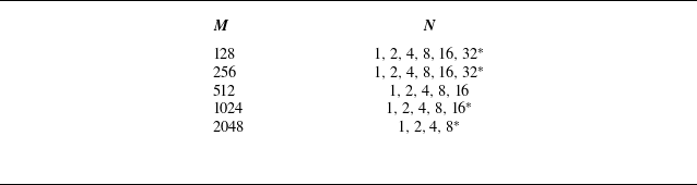


 Open access

