

1. Introduction
Evidence of past deglaciation can be measured directly through collection of subglacial bedrock samples. Collected subglacial bedrock samples can be analyzed for cosmic ray exposure, constraining deglaciation from past periods of warmer climate. The effects of future deglaciation are substantial for modern coastal infrastructure as sea level change can be impacted by the melting of ice sheets in Antarctica and Greenland (Schaefer and others, Reference Schaefer2016). Scientific interest, driven by the U.S. Ice Drilling Program (IDP) Subglacial Access Working Group, has led IDP to procure a commercially available rock coring rig and to modify and incorporate new technology into the rig to access subglacial bedrock.
After the evaluation of several techniques, a rotatory drill rig was chosen for durability and versatility of retrievable samples. The Winkie Drill is among the lightest commercially available exploration rigs on the market that meets all requirements set by the science community. Modifications were made to the rig and specialized equipment was added to the inventory to facilitate drilling through ice.
2. Requirements and system design
IDP made the decision to procure a rotary diamond-coring rig after evaluating likelihood of success with possible drill techniques, considering weight, reliability and cost. Tethered electromechanical drills have an extensive history in polar regions and have reliably collected ice cores. Many are light weight and easily transported to deep field sites. There has been some success in collecting debris-containing ice and bedrock samples with tethered systems; however, the reliability of current systems to collect bedrock is somewhat low and the risk of sticking and losing downhole equipment is increased (Bentley and others, Reference Bentley and Koci2007; Talalay, Reference Talalay2013). Further development of tethered systems could mitigate risk and increase capability but there are limitations to the adaptability of bedrock interfaces (Wang and others, Reference Wang, Cao, Liu and Talalay2015). After evaluation of current and readily available technology, IDP decided that a diamond-coring rig would have the highest probability of success of meeting the science requirements outlined in Table 1. A surface-driven, diamond-coring rig will be heavier than a tethered system; however, a diamond-coring rig can produce high continuous bit pressure and pull-back force.
Science requirements of the IDP Winkie Drill

Prior to the acquisition of a Winkie Drill by IDP, this system was used for sediment coring by the New Zealand Antarctica Program. The drill was first acquired by New Zealand's Department of Scientific and Industrial Research (DSIR) in 1979 and used in the Eastern Taylor Valley the following three years. Modifications were made to the drill in 2000 to use air circulation. During this time, operation of the drill was conducted jointly by Webster Drilling and the Antarctic Research Centre. Two coring projects were completed with the modified drill (Talalay and Pyne, Reference Talalay and Pyne2017; personal communication from A. Pyne, 2020).
The Winkie Drill fills a niche role within IDP's arsenal as the lightest rock sampling drill. The rig uses conventional rotary coring techniques common throughout minerals exploration industry. A drill string of jointed pipes is advanced through the access hole into the glacier and collects the bedrock sample below. Bit cooling and chip transport are accomplished entirely by forward circulation. Conventional coring was chosen rather than wire-line coring.
Wire-line coring could reduce rod tripping time but adds weight and complexity (Wang and others, Reference Wang, Cao, Liu and Talalay2015). A wire-line system uses a winch and cable to retrieve the core through the drill rod. In conventional coring, the entire drill string must be pulled from the borehole to collect the core sample. The required 1.5 m of bedrock fits within one core barrel length, so many coring runs are not required. The relatively shallow hole requirements result in an acceptably short rod-tripping time. Finally, the aluminum AW drill rods used by the Winkie Drill are not compatible with wireline systems. Therefore, a conventional coring approach was chosen.
A comparison of the limited number of commercially available rigs in this class resulted in the selection of the Winkie Drill based on criteria of system weight, availability, durability, proven history and cost. The Winkie Drill is the lightest readily available system on the market. IDP discussed custom rigs with various manufacturers but ultimately decided to go with the Winkie Drill due to reliability and cost considerations.
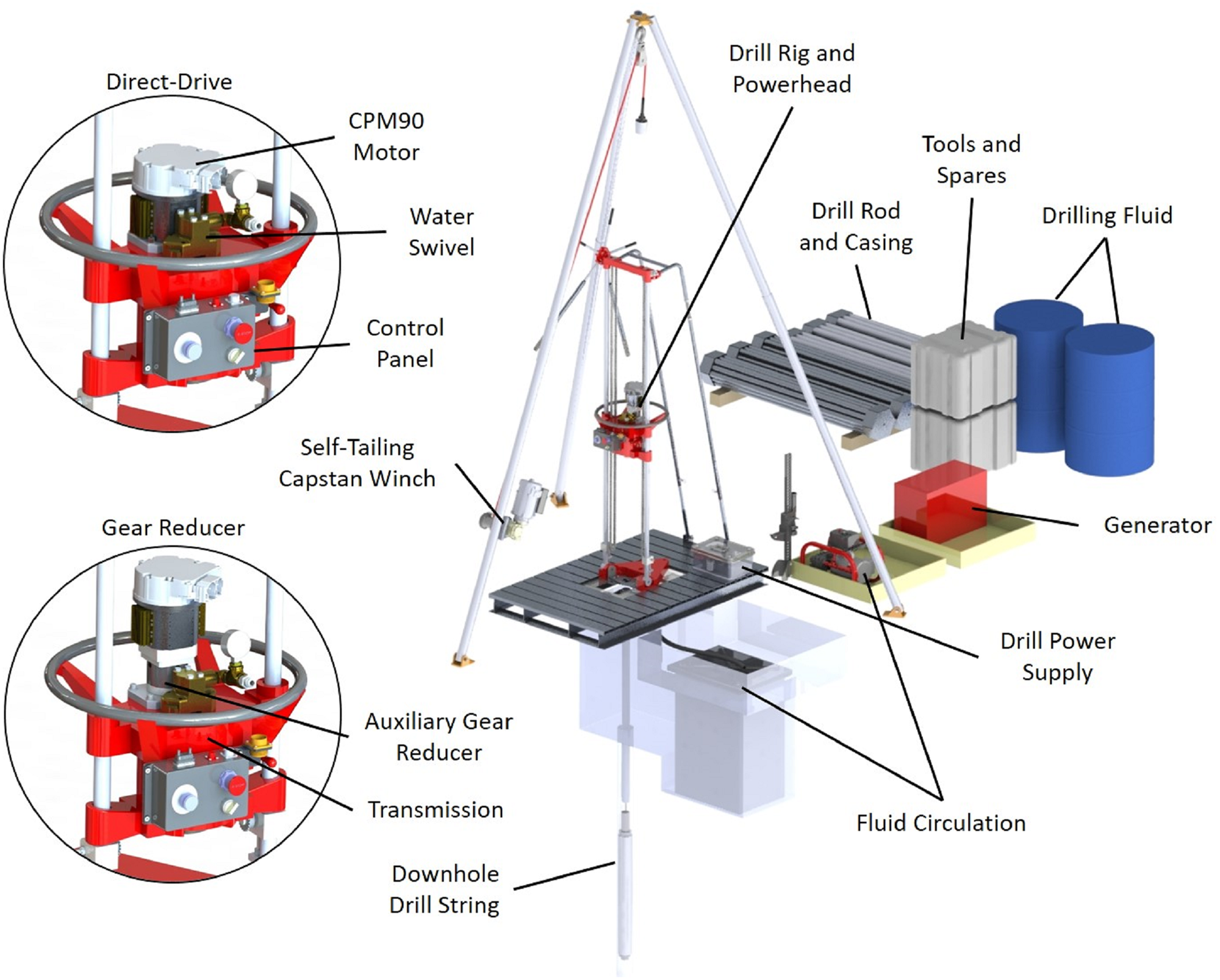
The scientific goals of each project vary, primarily due to site conditions. The design requirements of the drill system have also evolved with projects; however, the basic drill platform has been designed to fit all the requirements outlined in Table 1. The Winkie Drill is composed of three main subsystems: The drill rig and powerhead, the downhole tooling and the circulation and filtration system, as seen in Figure 1. The drill rig and powerhead control the movement of the downhole drill string. The downhole tooling cores and collects the sample. The circulation system flushes fluid across the bit at the bottom of the drill string, cooling and removing cuttings. The fluid is filtered and recirculated to minimize environmental impacts and reduce cargo weight.
Winkie Drill configured for a firn site (i.e. includes casing and packer). All other major components are included in every project.
2.1 Rig frame and powerhead
The operator controls the downhole tooling from the surface by means of the drill rig frame and powerhead. Pullback force and feed pressure are both controlled via the hand wheel. The hand wheel transfers force from the wheel to the powerhead (and drill string) via a standard ANSI #41-type roller chain. The Unipress frame supports the weight of the powerhead and the drill string while also counter-acting the rotational force of the powerhead. The powerhead consists of the drill motor, gear reducer, gear selector, water swivel and control panel. The Winkie Drill utilizes a top drive layout, meaning the drill string attaches to the bottom of the powerhead. The components are presented in Figure 1.
As purchased, the drill rod rotation is powered by a US Motor Power US820 2-stroke gasoline engine. This engine was used during the first field deployment in 2016/17 to the Ohio Range in Antarctica. Operation of the engine in a polar environment was cumbersome. The noise from the exhaust made communication between operators nearly impossible, adding risk and slowing operations. Later in 2017, the gasoline engine was replaced with an electric motor. Hydraulic motors were also explored as a replacement. Winkie drills have been converted to hydraulic systems by other organizations and have worked well; however, the hydraulic systems require a hydraulic pump, hydraulic fluid, high-pressure hoses and are ultimately run by a gasoline engine. This pump is heavy, loud and an additional machine to maintain in the field. Hydraulic systems also require preheating when operated in cold temperatures. The added complication and failure points of hydraulic hoses tipped the decision to pursue an electric motor rather than a hydraulic system. An electrical generator is already required to power other components of the system. Maintaining a single generator as the source of power for the system further increases operation efficiency despite additional energy losses in the conversion of fuel to electricity, power conversions and line losses.
An electric motor with equivalent performance to the US820 gasoline engine was not identified. The closest performing motor, a Sonzeboz CPM90-5924 brushless DC motor, was used during the 2017 redesign. However, this motor was not in production in 2020 during the building of a second Winkie Drill, so the CPM90-5924 was replaced with the newer CPM90-5934-48V. The torque curves of the CPM90-5924 (personal communication with Sonceboz) and CPM90-5934-48V (Sonceboz Compact Power BLDC CPM90 5934-48V preliminary datasheet: https://cpm90.com/wp-content/uploads/2018/05/CPM90-5934-48 V-4.0.pdf) are plotted in Figure 2 with the US820 gasoline engine. The maximum speed of the US820 engine is higher (8000 rpm) than is possible with either electric motor (7000 rpm). Installing the CPM90-5934-48V resulted in slower rod rotation, reducing production rate of core in bedrock. However, the limited amount of core required by the science objectives means the reduced production rate is negligible for the overall timeframe of the project. If needed, an auxiliary 3 : 1 gear reducer can be added between the CPM90-5934-48V motor and transmission to increase torque output. This was used during the Ong Valley field season to accommodate an over-sized core barrel. The Winkie powerhead has two selectable gears: high with a 3 : 1 gear reduction, and low with 7 : 1 reduction. The result is four distinct gear reduction values – 3 : 1, 7 : 1, 9 : 1 and 21 : 1. Therefore, the Winkie with CPM90-5934-48V motor can operate at speeds up to 2333 rpm in high gear without the auxiliary gear reducer. The maximum torque at the drill rod is 255 Nm at 95 rpm in low gear with the auxiliary gear reducer.
Both CPM90 electric motors produce less power than the US820 gasoline engine. However, the torque curves of the motors reveal that under high loads the speed will decrease when more torque is required. The values do not include gear reduction.

With the addition of the electric motor came the addition of a control panel to the front of the powerhead, DC power supply and increased generator size. The control panel includes an emergency stop button, drill speed knob and circulation mud-pump switch. All controls are accessible to the operator while using the OEM hand wheel fitted with extension bars.
The power supply is a Mean Well RSP-3000-48 unit, converting 240 VAC power from the generator to 48 VDC with maximum power output of 3 kW. The power supply is housed in an enclosure for environmental protection and is fitted with a 6 m cable to allow the supply to be positioned safely away from the drill operations.
The addition of the electric motor increased the electric power requirement of the drill relative to the gasoline powered rig configuration. The peak power draw by the system is 4.69 kW, requiring both 120 and 240 VAC. Power has previously been supplied by Honda gasoline generators.
A tripod was included with the Winkie Drill at the time of purchase. The tripod has been retrofitted with a self-tailing capstan winch to minimize rod and casing tripping times. The winch is a Harken 40.2STE, two-speed model. The winch can be operated with either a hand crank or 0.37 kW electric motor. The motor has been fitted with a power rectifier to convert 120 VAC generator power to 90 VDC and a foot switch to allow for two-handed rope handling. The tripod has been load tested to 45 kN.
With the exception of the tripod, the rig is mounted to a custom 1 m by 1.7 m aluminum pallet. The pallet provides a safe working area around the borehole, prevents borehole collapse and distributes the weight of the rig and drill string evenly over the glacial surface. The pallet is anchored to the surface with either ice screws or dead-man anchors.
2.2 Downhole tooling
Subglacial drilling requires tooling similar to that used in traditional geologic drilling, but with added complexity due to the presence of ice. Custom bits and procedures must be designed to create an access hole to the underlying bedrock. Once bedrock is reached, standard rock bits can be used.
At the surface, most glaciers are porous snow or firn. Drill fluid must be prevented from flowing into these upper layers. This is done with casing and an inflatable packer. In regions with ‘blue ice’ at the surface, normally casing is not necessary though could be required if the blue ice is fractured. Industry standard casing and custom lightweight options were explored. Ultimately, the slight weight savings was not worth the cost or lessened availability of a custom tube, and industry standard BTW drill rod was chosen as the casing. BTW specifications are given in Table 2.
Summary of the industry standard downhole tooling

To install the casing, a pilot hole must be drilled through the upper firn layers to ice sufficiently dense to contain drill fluid. Through testing near McMurdo Station, Antarctica, IDP concluded that the minimum ice density that will contain pressurized fluid is 860 kg m−3. A drilling method that does not require drill fluid must be used to generate this pilot hole. Two approaches were considered: continuous-flight augers, or an electro-mechanical coring drill. Ultimately, IDP chose the electro-mechanical Eclipse Drill owned by IDP to create the access hole for three reasons: (1) the Eclipse Drill leaves an almost perfectly clean hole, while the augers could leave a large quantity of chips in the borehole, (2) the Eclipse Drill is a standalone system and can be operated simultaneously with Winkie Drill coring operations, sharing only tools between systems and (3) firn density measurements can be made with recovered cores, ensuring that the packer is placed at an appropriate depth. While the Eclipse Drill is heavier than augers (565 kg vs 250–450 kg respectively), the advantage of a clean and measured hole tipped the decision in favor of the Eclipse. The Eclipse Drill creates a 113 mm borehole.
The packer referred to above is an inflatable type and is the primary equipment used to seal the casing to the ice at the bottom of the pilot hole. An inflatable packer seals the casing to the borehole wall with an elastomeric element, pressurized with dried air. The packer used with the Winkie Drill system was procured from QSP Packers, LLC and the specifications are given in Table 3. The packer is inflated by a high-pressure air compressor. To prevent ice blockages in the inflation line, the tanks in the compressor are filled to 3.4 MPa and allowed to cool, condensing some of the moisture. The air is also filtered and dried with an inline desiccant before entering the 6.35 mm nylon inflation line. The packer is never inflated to more than 1.4 MPa.
Summary of the Winkie Drill inflatable packer specifications

After installation of the casing and inflation of the packer, drill rod with a bit appropriate for the formation is tripped into the borehole. The aluminum AW drill rods used by the Winkie drill are readily available in the commercial marketplace and reduce weight compared to steel alternatives. The aluminum rods are 1.52 m in length. AW drill rod specifications are given in Table 2.
The bottom hole assembly (BHA) consists of two options: a core barrel and coring bit or a full-diameter ice bit. When the packer is placed far above the rock surface, a quick method for drilling through the ice to the bedrock below is desirable (if ice samples are not required). The ice bit depicted in Figure 3 is designed to cut the entire hole diameter, allowing for continuous drilling without the need to trip rods and remove core from the core barrel. The bit has been subjected to limited testing, but other drill rod rigs such as the IDP Agile Sub-Ice Geological (ASIG) Drill and U.S. Rapid Access Ice Drill (RAID) have successfully implemented similar designs. The key difference between those designs and the Winkie rig is that they can operate in reverse circulation (pumping the chips up the center of the drill rod), while the Winkie is confined to only forward circulation.
Full-diameter ice bit is designed to advance a borehole through clear ice to the bedrock below by chipping the full diameter ice and transporting it via fluid circulation to the surface. Field testing of the bit is planned.

When coring, a double-wall AW34 core barrel assembly is used. The suite of coring bits included with the system includes diamond-impregnated bits, geoset bits, polycrystalline diamond compact (PDC) bits, and hybrid impregnated bits, Figure 4. The geoset cutting face is formed from thermally stable polycrystalline diamond cast into a tough metal-alloy matrix. The bit is designed for soft to medium-hard formations. The results of three field deployments have showed this bit to be the most effective in the range from clean ice to ice-cemented sediment. In hard bedrock formations, the bit dulls quickly, in some cases after as little as 10–20 cm of core. Because the geoset bit dulls quickly in hard bedrock, conventional diamond-impregnated bits are included with the drill system. Hard formation bits (#10 matrix or softer) are best suited for these short core applications because it reduces the risk of bit glazing. Impregnated bits cannot be used if ice is present in the kerf of the bit, as the ice glazes the bit surface. PDC bits have successfully been tested (Cao and others, Reference Cao, Yang, ChenY and Talalay2015) and recovered cores with other subglacial drill systems (ASIG and RAID). Use of PDC bits was attempted unsuccessfully in two field seasons. Fluid circulation was stopped due to sediment plugging at the bit whenever the borehole bottom was reached. Possibly, the annular space of the AW34 core barrel is too small for the ice chips to evacuate with the more aggressive PDC bit.
Winkie Drill is equipped with four bit designs. The #10 diamond-impregnated bit is used in hard bedrock formations. The geoset bit is used in soft rock formations or when sediments are entrained in the ice. The PDC bit can be used in similarly soft rock formations but has had limited success when ice is present in the kerf. The hybrid impregnated bit is made from the same material as the standard #10 diamond-impregnated bit but includes a relief angle behind the leading edge. This bit can cut ice and transition into bedrock.

2.3 Fluid circulation
Conventional rotary drill rigs generally use a water-based circulation fluid. Water cannot be used for the circulation fluid in polar drilling applications for the obvious reason that it would freeze in the borehole. A considerable amount of research has gone into the selection of a drill fluid that meets the requirements of polar drilling (Talalay, Reference Talalay2011; Sheldon and others, Reference Sheldon, Popp, Hansen and Steffensen2014; Liu and others, Reference Liu2016). The decision to use Isopar K was based on the material properties of the fluid as well as its low toxicity, availability, cost and previous experience (IDP successfully used Isopar K at the WAIS Divide drill project). Isopar K is an isoparaffin fluid with density of 762 kg m−3 at 15.6°C and kinematic viscosity of 1.58 mm2 s−1 (Exxonmobil Chemical Isopar™ K Fluid Product Safety Summary: https://www.exxonmobilchemical.com/en/library/library-detail/2894/isopar_k_fluid_product_safety_summary).
The fluid circulation system operates in a closed loop. The fluid is pumped through the water swivel (a sealed rotary joint in the powerhead) and down the inside of the drill rods. If the full-diameter bit is installed, the fluid evacuates the rod through the center of the bit and flushes chips outward. If the core barrel is installed, the drill fluid is diverted between the inner and outer core barrel, preventing washing away of a brittle core and down to the bit. The fluid flows across the bit, flushing cuttings to the outside of the core barrel and up the annulus around the barrel and drill rod to the surface. To keep the system as light and simple as possible, the fluid simply spills over the top of the casing and into a tank with a drain and hose at the bottom. This hose directs the dirty fluid into the filter tank. At the top of the tank are filter bags, collecting all particles larger than 100 μm. Once through the filters, the drill fluid is held in the tank until the mud pump picks up the fluid and sends it back downhole. A simplified diagram of the system is shown in Figure 5.
Purpose of the drill fluid is to cool the bit and flush chips to the surface. The fluid is filtered and recycled in this closed loop system.

The mud pump is a triplex piston pump powered by an AC electric motor, with maximum flow rate of 11.4 L min−1 and maximum pressure of 2.07 MPa. The pump flow rate can be controlled by varying the speed of the motor with a 120 VAC variable frequency drive. The flow can vary from 0 to 11.4 L min−1. Typical operation flow rate is between 7.5 and 11.4 L min−1, resulting in fluid velocity up the annulus of 4.5 m s−1. A spare mud pump deployed with the drill system can be added in series to further increase the flow rate. The pump is also equipped with a variable pressure-relief valve. When the pumping pressure reaches a set value, the valve opens, recirculating the drilling fluid through the pump rather than down the borehole. This critical feature prevents hydraulic fracturing of the borehole wall. The valve is set to open at a default pressure of 1.0 MPa.
A challenge encountered by other subglacial rigs in recent years is hydraulic fracturing of the ice borehole. Hydraulic fracturing is the phenomenon of cracking the drilled material by over-pressuring the fluid until the material fails in tension. Once cracked, the borehole is no longer sealed and the closed loop circulation system is opened, releasing drill fluid into the environment. The phenomenon has occurred in tests (Chen and others, Reference Chen2019) as well as during coring operations in Antarctica. The conclusion of testing is that the failure pressure is dependent on several variables including micro-cracking along the borehole, ice temperature and overburden pressure (Chen and others, Reference Chen2019). Both the ASIG Drill and RAID have experienced hydraulic fractures during drilling operations. The data recorded by ASIG and RAID guided the setting of the packer to a maximum inflation pressure of 1.4 MPa, and maximum fluid circulation pressure at the output of the pump to 1.0 MPa.
3. Operation and performance
The operation of the Winkie Drill requires two trained personnel. Two operators are required for rod tripping as well as during coring; one for operating the powerhead and hand wheel and the other to monitor and maintain the fluid circulation and filters.
Drill sites must be selected to meet the capabilities of the drill. The maximum depth that can be drilled is 120 m. The surface can be snow, firn, blue ice or rock. In crack-free ice, casing is not required and can reduce the shipping weight of the system. At the bed, the ice must be frozen to the underlying surface. Voids or water layers will impede effectiveness of the circulation system and pose an environmental risk due to the release of drill fluid. Drill operations are simpler when there is little or no ice-cemented sediment above the bedrock because drilling this media is generally slower and requires changing coring bits.
Every piece of the packed rig can be lifted by two people, the heaviest weighing ~125 kg. Much of the system weight is the result of drill rod, casing and drill fluid, so the total shipping weight is a function of desired sample depth and composition of the covering glacier. For example, to collect a bedrock sample from beneath 50 m of impermeable blue ice, 1813 kg of gear with spares is required: Winkie Rig, four bundles of drill rods, two drums of drill fluid, a drum of fuel and other required camp gear. To collect a sample from a similar depth in firn the total system weight increases to 2808 kg with the addition of the Eclipse Drill, four bundles of casing, packer and inflation equipment. A breakdown of shipping weights and volumes is shown in Table 4.
Drill rig and essential equipment must be taken to each project site

Total weight will scale with the quantity of drill rod needed to reach the desired depth. If the site is in blue ice, the casing and packer equipment do not need to be included. All weights include cases for shipping.
The IDP Winkie Drill has deployed to Antarctica on three separate projects. During the 2016/17 Antarctic season, the drill collected core from the Ohio Range. The drill was then adapted and deployed in 2017/18 to the Ong Valley to collect 71.7 mm diameter dirty ice cores. The drill was then reverted to the 33.5 mm AW34 core diameter configuration and successfully collected samples during the 2019/20 season from Mount Murphy as part of the International Thwaites Glacier Collaboration. A summary of results are shown in Table 5.
Summary of the results of three field deployments of the Winkie Drill

The total weight estimate includes drill fluid, fuel and generators.
3.1 Ohio Range
The goal of the Ohio Range project was to collect six bedrock samples from depths varying from 10 to 30 m, with an optional 50 m attempt. Eight access holes were drilled resulting in six geologic samples: five bedrock samples and a sixth sample of entrained sediment. Hole depths and core lengths are given in Table 6. Drilling was performed near two nunataks known as Papa Bennett and Baby Bennett. At the Papa Bennett site (boreholes #1–6) all boreholes were within several meters of each other, and in crack-free blue ice. Because casing was not needed, 50.8 mm diameter continuous-flight augers were used to create the access holes to the bedrock (the full-diameter ice bit had yet to be designed). The augers worked well, quickly creating clean holes to 30 m depth. Beyond 30 m, there was risk that the connections on the augers would fail. This happened on two occasions, and a specialty retrieval tool was fabricated in the field. The augers left some chips in the bottom of the hole, ranging in depth from 0.50 to 1.23 m. The augers were spun at 1500 rpm to clear chips once the bedrock was reached.
Eight boreholes were attempted at the Ohio Range during the 2016/17 field season

Six geologic samples (five bedrock cores) were collected.
A sample was recovered from borehole #4 but inspection determined it was a specimen suspended in the ice above the bedrock. The presence of entrained material above the bedrock interfered with the scientific measurements so the borehole was abandoned. Only 30 m of augers were present at the field camp when borehole #6 was drilled. The bedrock was not reached with augers and attempts to advance the borehole with drill rods was unsuccessful as a modified Forstner-style woodworking bit was not effective at clearing chips with drill fluid circulation. Additional augers were brought to the drill site for borehole #8 but connection failure at the joints halted drilling before bedrock was reached. Two auger sections were buried by chips in the bottom of the borehole and could not be retrieved.
Because casing was not used, the diverter tank was not an option. Instead, the fluid was redirected into an ice sump where the fluid could be pumped into the filtration tank with a drum pump. See Figure 6 for an image of the temporary collection sump.
An ice sump was cut into the surface of the blue ice to collect the fluid and chips as they were pumped to the surface.

The field season was a success and proved that the Winkie Drill could recover shallow subglacial rock samples. Key successes included verification of the geoset bit as the primary mixed media bit. Also, continuous flight augers can effectively transport chips to the surface and leave a nearly clean hole when a bore wall can support the augers without erosion. Critical changes made to the drill following the season include the replacement of the US820 gasoline engine with the CPM90 electric motor and addition of a tripod with winch for quicker rod tripping.
3.2 Ong Valley
Ong Valley is nestled within the Miller Range of the Transantarctic Mountains. The Argosy Glacier at the outlet of the valley was thought to have advanced into the valley and ablated, leaving ~1 m of overburden above debris-rich ice. The project was to collect sufficient debris samples from the ice for radionuclide testing at two discrete sites (Bibby and others, Reference Bibby, Putkonen, Morgan, Balco and Shuster2016). To maximize the particulates collected, the rig was adapted to drill with an 86-T2 core barrel, which collected a 71.7 mm diameter core. The borehole summary is given in Table 7.
Two boreholes were drilled, collecting a continuous core sample from the ice surface

Drill fluid was collected from the borehole following the completion of the borehole so lost fluid was due to evaporation, fluid lost on drill rods during tripping, and fluid left in filtered chips.
Two drill sites were selected in the valley. Approximately 0.6 m of dry debris was present above the ice surface at each site. Prior to drill assembly, the debris was removed and a wooden barrier assembled to prevent debris from reentering the borehole and fluid sump. The ice was free of cracks so again the drill fluid was pumped from an ice sump into the filter tank. The wooden barrier and ice sump are presented in Figure 7.
(a) At the Ong Valley drill sites a layer of sediment was covering the ice surface. Once the ice was exposed, a timber barrier was built to support the drill rig and prevent loose sediment from falling into the borehole. (b) A channel was carved into the marbled ice to direct the drill fluid to a sump where it could be pumped into the filter tank. The borehole was drilled into the center of the bowl at the bottom of the image.

The ‘dirty’ ice proved to be quite difficult to drill, often resulting in plugged water ways in the bit. When this occurred, the only way to reestablish circulation was to trip the rods to the surface and clean the bit. Core production was slow, averaging ~2 m per day. Figures 7(b) and 8 show the ice and core composition. Experimentation with the geoset, PDC and hybrid impregnated bit showed that only the geoset bit cut this material without plugging. Penetration rates of the geoset bit varied from 2 to 30 mm min−1. The most reliable drilling parameters were as follows:
• drill no more than 1 m per run
• at the completion of the run, circulate fluid for several minutes (with the drill string rotating) to clear chips at maximum flow rate (11.4 L min−1)
• stop rotation and break the core with the drill rig
• lift the drill string with the Unipress, if at any time the drill string begins to bind, start fluid circulation and drill string rotation
• once lifted ~1 m, the tripod and winch can be used to trip rods.
In its second field deployment, the Winkie Drill again completed its field objectives. Key advancements included proving the CPM90 electric motor and gear reducer combination for oversized core collection.
Core at Ong Valley was especially complicated to drill because it very quickly changed from clean ice, to thin clay layers, to rocks several centimeters in diameter.

3.3 Mount Murphy
The Mount Murphy project was part of the International Thwaites Glacier Collaboration between the USA and UK, searching for signs of a previous collapse of the Thwaites Glacier. The drilling goal was to collect 1.5 m bedrock cores from six sites with overlying ice depths ranging from 10 to 60 m. This was the first project that utilized casing, a packer and the IDP Eclipse Drill for pilot holes. The season resulted in six access holes and four bedrock samples. The borehole statistics are given in Table 8.
Six access boreholes were drilled with the IDP Eclipse Drill

Bedrock samples could not be collected from borehole #2 because the access hole filled with meltwater. Borehole #3 did not reach bedrock when expected and it was theorized that the borehole missed the buried ridge. With an unknown amount of cosmic shielding, the sample would be inconsequential, so the borehole was abandoned.
The boundary layer near the bed contained a mixture of rock and ice and slowed drill progress. The geoset bit was the only bit that made significant progress through this layer. Complications were furthered by warm ambient conditions at the surface, warming the temperature of the drill fluid. Often, the fluid was only −1 to −2°C when it was pumped down the hole. The temperature of the fluid was further warmed by heat generated at the bit. This warm fluid caused melting of the borehole wall that later refroze in the casing. Figure 9(a) shows the melted borehole wall; only cemented pebbles remain at the original bore diameter. Figure 9(b) shows a plug that was formed in the casing by refrozen water and cuttings. The water that was generated at the BHA by the warm fluid and friction froze to the casing bore as it was pumped upward. The rod and BHA managed to trip through the ice layer on the way out of the borehole but when attempting to reenter the borehole, the ice chipped off the casing wall and formed a plug in front of the bit.
(a) Warm fluid near the bit resulted in an eroded borehole wall. (b) The water refroze further up in the casing, resulting in flakes that plugged the casing.

The Winkie Drill again collected significant scientific samples during its third Antarctic deployment. The addition of casing and an inflatable packer were successfully implemented, allowing for drilling in firn locations. The geoset bit continues to be the bit of choice for mixed media drilling; however, warm fluid caused complications and reduced efficiency. At locations with temperatures near freezing, a scheme to cool fluid must be added.
4. Conclusions
The ability to collect subglacial samples is a resource the scientific community will use to accurately constrain past periods of deglaciation. The Winkie Drill is the smallest of the recently developed subglacial access drills and fills the need for a lightweight drill that can drill to depths as far as 120 m. The IDP Winkie Drill is a modified version of the commercially available rig sold by PHQ Global, Ontario, Canada. Major improvements made by IDP include the replacement of the gasoline engine with an electric motor, the addition of a closed-loop circulation system and implementation of ice-specific tooling. The Winkie Drill has successfully completed three drill seasons, collecting bedrock samples from a maximum depth of 42.8 m. The drill can collect core samples of ice, rock or a mixture of ice-cemented particles. The top of the borehole can be cased to seal against fluid loss into the firn. Future improvement will likely involve exploration into more efficient means of drilling through entrained sediments in ice.
Acknowledgements
IDP benefits from the exceptional support of many organizations in developing new drill systems and this development effort was no exception. All merit acknowledgement and our sincere appreciation. In particular, we thank the members of the IDP Technical Advisory Board (TAB) for their ongoing advice and assistance; the University of Wisconsin-Madison, particularly the Space Science and Engineering Center, for providing exceptional support; the Arctic and Antarctic support contractors and the US National Science Foundation (NSF) Office of Polar Programs for making it all possible. This work was supported under NSF Cooperative Agreements OPP-1327315 and OPP-1836328.


 Open access