


1 Introduction
Random Raman fiber lasers (RRFLs) have garnered increasing attention due to their unique lasing characteristics and structural simplicity[ Reference Churkin, Babin, El-Taher, Harper, Kablukov, Karalekas, Ania-CastaÓn, Podivilov and Turitsyn 1 – Reference Zhang, Lin, Bao, Wang, Qi, Wu, Liang and Wang 5 ]. As a novel laser source, RRFLs demonstrate potential applications in distributed fiber sensing[ Reference Han, Wu, Liu, Dong, Rao, Wang, Xu and Ma 6 – Reference Deng, Churkin, Xu and Shu 8 ], imaging[ Reference Wu, Han, Wang, Genty, Feng and Liang 9 , Reference Ma, Rao, Zhang and Hu 10 ] and frequency doubling[ Reference Dontsova, Kablukov, Vatnik and Babin 11 , Reference Cui, Qian, Zeng, Cheng, Gu and Feng 12 ]. Unlike conventional lasers relying on resonant cavities, RRFLs employ random distributed feedback and Raman gain within fibers, achieving wavelength-tunable, highly robust laser outputs with exceptional tolerance to environmental perturbations[ Reference Balaswamy, Ramachandran and Supradeepa 13 , Reference Vatnik, Churkin, Babin and Turitsyn 14 ]. These advantages position RRFLs as strong candidates for next-generation high-power laser sources. Particularly noteworthy is their superior temporal stability, enabling deployment as seed lasers in power amplification systems, thereby significantly expanding their industrial and scientific applicability[ Reference Du, Zhang, Ma, Xiao, Wang, Zhou and Liu 15 – Reference Li, Li, Ke, Zha, Peng, Sun and Ma 17 ].
To achieve high-power RRFLs, the half-open cavity architecture incorporating point reflectors (e.g., high-reflection fiber Bragg gratings, HR-FBGs) and a random feedback mechanism has emerged as the dominant design strategy[ Reference Ye, Zhang, Liang, Ma, Xu, Yao, Leng and Zhou 18 – Reference Qi, Li, Fu, Yang, Li, Wang, Du, Yan, Gong and Xiao 24 ]. This configuration reduces the lasing threshold through enhanced feedback, thereby facilitating unidirectional laser emission. As early as 2015, Wang et al. [ Reference Wang, Wu, Fan, Zhang, Rao, Zhang and Jia 23 ] constructed a random fiber laser utilizing a semi-open cavity with point reflectors. The 1090 nm laser served as the pump source, generating 7 W of random lasing at 1140 nm. Current RRFL implementations based on this approach have attained output powers of 2 kW[ Reference Ye, Zhang, Liang, Ma, Xu, Yao, Leng and Zhou 18 ]. However, during power scaling in such architectures, backward-propagating power exhibits nonlinear amplification. Recently, our research group theoretically and experimentally demonstrated that the presence of multi-longitudinal modes in a laser source can result in random laser output from one side, even in a fully open cavity[ Reference Zhang, Xiao, Wang, Zhou and Xu 25 , Reference Zhang, Wu, Wan, Wang, Yang, Xi, Wang and Zhou 26 ]. Further optimization of fiber length yielded random lasing outputs exceeding 1200 W[ Reference Zhang, Wu, Wan, Wang, Yang, Xi, Wang and Zhou 26 ]. In 2023, Ye et al. demonstrated a 2 kW hybrid Yb-Raman gain-based random laser using a superfluorescent fiber source (SFS) as the Raman pump seed[ Reference Ye, Zhang, Liang, Ma, Xu, Yao, Leng and Zhou 18 ]. The implemented SFS exhibits a core diameter of 20 μm. While SFS seeding enhances temporal stability, it introduces significant system complexity. Researchers typically employ few-mode fibers (FMFs) with 20 μm cores in fiber lasers to maintain modal purity[ Reference Ye, Zhang, Liang, Ma, Xu, Yao, Leng and Zhou 18 , Reference Song, Ren, Liu, Li, Wu, Ma, Zhang and Zhou 19 ]. However, FMFs exhibit limited power density tolerance, constraining their output power scalability. Multimode fibers (MMFs) with larger core diameters are required to achieve higher power levels. In 2024, Wu et al. [ Reference Wu, Wang, Zhang, Wu, Xi, Shi, Yang, Wang, Han and Chen 27 ] constructed a kW-level fully open cavity RRFL using a conventional oscillator and the 25 μm core fiber. Compared to the SFS system, this conventional architecture reduces system complexity. However, the multimode support of MMF induces mode overlap, resulting in degraded spectral purity and Stokes conversion efficiency, thereby negating the high-power-density advantages of MMFs. Extended propagation distances intensify nonlinear interactions, lowering the threshold for higher-order Raman components and enabling cascaded energy transfer to higher-order modes (HOMs). Collectively, power scaling in fully open cavity RRFLs is constrained by mode mismatch, leading to suboptimal Stokes conversion efficiency and output power.
Recent advancements in fiber technology have introduced novel fibers featuring longitudinal core diameter variations. These fibers exhibit progressive changes in geometric dimensions and mode-field distributions, enabling significant suppression of nonlinear effects[ Reference Filippov, Chamorovskii, Kerttula and Okhotnikov 28 – Reference Trikshev, Kurkov, Tsvetkov, Filatova, Kertulla, Filippov, Chamorovskiy and Okhotnikov 30 ]. Research institutions worldwide have successfully demonstrated the generation of high-brightness fiber lasers through engineered tapered optical fiber architectures[ Reference Filippov, Chamorovskii, Kerttula and Okhotnikov 28 – Reference Gao, Zhang, Xu, Lu, Chen and Bao 36 ]. Due to their varying core and cladding sizes, tapered fibers can effectively suppress nonlinear effects such as stimulated Raman scattering (SRS)[ Reference Zeng, Wang, Ye, Wang, Yang, Xi, Wang, Pan, Zhang, Shi, Han and Xu 33 ] and four-wave mixing (FWM)[ Reference Zhang, Ye, Zhou, Wang, Leng, Xu, Wu and Xu 35 ]. In 2016, Gao et al. [ Reference Gao, Zhang, Xu, Lu, Chen and Bao 36 ] implemented a Brillouin random fiber laser (BRFL) using a 5 km tapered fiber. The results demonstrate that tapered fibers enhance Rayleigh scattering. Furthermore, this configuration provides substantial coherent random distributed feedback. In 2023, Wang et al. [ Reference Wang, Xiao, Xi, Liu, Li, Pan, Yang, Yan, Chen, Huang, Wang, Yang, Wang, Ma and Wang 37 ] reported 10 kW high-brightness laser output in a tandem pumping fiber laser based on tapered fiber. In 2024, Chen et al. [ Reference Chen, Huang, Huang, Yan, Pan, Jiang and Zhou 38 ] experimentally validated that tapered MMF can effectively preserve mode characteristics while achieving kW-level laser output over transmission distances exceeding 100 m. The application of tapered fibers in fully open cavity RRFLs can solve the problem of mode control.
To further enhance output power and Stokes conversion efficiency, in this work we design a tapered germanium-doped fiber (T-GDF) with mode-preserving functionality. By integrating mode control and end feedback management, 2 kW random lasing output was achieved in a fully open cavity configuration. Theoretical simulations and experimental comparisons validated the impact of end feedback on Stokes power distribution. Optimizing the T-GDF length improved spectral purity and suppressed higher-order Stokes components. At the power of 2081 W, spectral purity exceeded 90%, representing the highest reported Stokes conversion efficiency for this cavity type to date. This study provides important reference for high-power random Raman laser development and multimode nonlinear effect investigations.
2 Experimental setup
Utilizing a home-made T-GDF, we constructed a fully open cavity RRFL, with the schematic diagram illustrated in Figure 1. The oscillator section employs a pair of fiber Bragg gratings (FBGs) centered at 1080 nm to form the resonant cavity. The reflectivities of the HR-FBG and output coupler (OC) FBG are 99.5% and 10% with 3 dB bandwidths of 3 and 1 nm, respectively.
System configuration of the high-power fully open cavity RRFL. LD, laser diode; B-PSC, backward-pump/signal combiner; F-PSC, forward-pump/signal combiner; HR-FBG, high-reflection fiber Bragg grating; OC-FBG, output-coupling fiber Bragg grating; T-GDF, tapered germanium-doped fiber; CLS, cladding light stripper.
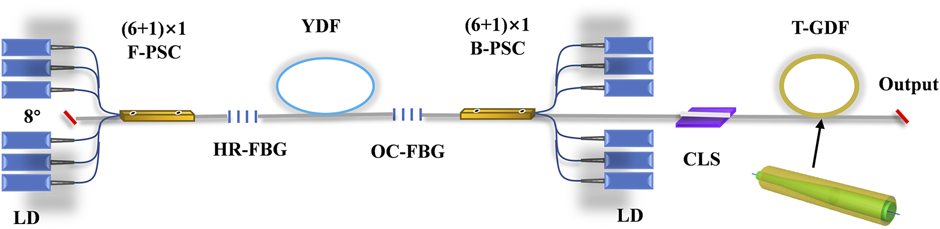
A 35-m-long ytterbium-doped fiber (YDF) with 25 μm core and 400 μm cladding diameters is deployed within the cavity. A bidirectional pumping configuration is adopted to enhance output power. Six 940 nm laser diodes (LDs) are connected to the forward-pump/signal combiner (F-PSC) and backward-pump/signal combiner (B-PSC), respectively. The signal output and pump input fibers of the combiners match the YDF diameters, ensuring mode-matched splicing. The F-PSC signal fiber is angle-cleaved (8°) to mitigate back-reflection effects. The B-PSC output fiber is integrated with a cladding light stripper (CLS). The 1080 nm fiber laser emitted from the oscillator with an output power of more than 3 kW is delivered through the T-GDF.
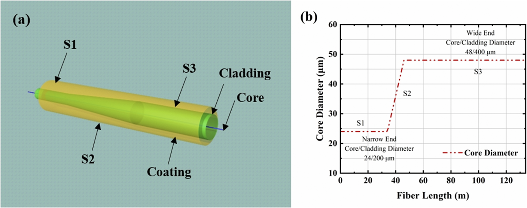
Figures 2(a) and 2(b) depict the three-dimensional (3D) schematic diagram of the T-GDF and the longitudinal evolution of its core diameter along the fiber length, respectively. During the tapered fiber fabrication, geometric gradients across distinct taper sections were achieved by precisely controlling the drawing speed within the fiber drawing tower. The designed tapered MMF is partitioned into three sections: S1 (narrow end), S2 (tapered section) and S3 (wide end), with corresponding lengths of 30, 10 and 90 m. The narrow end and wide end exhibit core/cladding diameters of 24/200 and 48/400 μm, respectively. The T-GDF was strategically designed with dual objectives: (i) enhanced conversion efficiency from the 1080 nm fiber laser to the random Raman laser through optimized length-dependent phase matching, thereby elevating the first-order Stokes threshold; (ii) superior mode characteristic preservation compared to conventional fibers. Validated through both theoretical and experimental approaches, this fiber effectively maintains modal properties during extended propagation[ Reference Chen, Huang, Huang, Yan, Pan, Jiang and Zhou 38 ], consequently suppressing higher-order Raman components by reducing their generation thresholds.
(a) Three-dimensional schematic diagram of the longitudinal structure of the T-GDF. (b) Core size distribution of the T-GDF.

3 Experimental results and discussion
3.1 Impact of end feedback in fully open cavity RRFLs
In fully open cavity RRFLs, end feedback significantly impacts both output power and backward-propagating light[ Reference Zhang, Wu, Wan, Wang, Yang, Xi, Wang and Zhou 26 , Reference Wu, Wang, Zhang, Wu, Xi, Shi, Yang, Wang, Han and Chen 27 ]. To elucidate the effects of end feedback, comprehensive theoretical and experimental analyses were conducted. While the nonlinear Schrödinger equation (NLSE) can simulate forward/backward mode-resolved power in fiber lasers, its calculation is somewhat complicated. To address computational complexity and mode coupling, we established a multimode RRFL theoretical model that resolves power evolution across transverse modes in both signal and random lasing processes. The random laser model incorporating multimode Raman interactions is defined as follows:
 $$\begin{align}\frac{\partial {P}_\mathrm{k}^{s_1\pm }}{\partial z}+\frac{1}{v_{\mathrm{g}_1}}\frac{\partial {P}_\mathrm{k}^{s_1\pm }}{\partial t}&=\mp {g}_{\mathrm{R}_1}{P}_\mathrm{k}^{s_1\pm}\sum \limits_j\left({P}_j^{s_2+}+{P}_j^{s_2-}\right){r}_{\mathrm{k}j}\nonumber\\&\quad-{\alpha}_\mathrm{k}^{s_1}{P}_\mathrm{k}^{s_1\pm}\pm {\eta}_\mathrm{k}^{s_1}{P}_\mathrm{k}^{s_1\mp },\end{align}$$
 $$\begin{align}\frac{\partial {P}_\mathrm{k}^{s_2\pm }}{\partial z}+\frac{1}{v_{\mathrm{g}_2}}\frac{\partial {P}_\mathrm{k}^{s_2\pm }}{\partial t}&={g}_{\mathrm{R}_1}\frac{\lambda_{s_2}}{\lambda_{s_1}}{P}_\mathrm{k}^{s_2\pm}\sum \limits_j\left({P}_j^{s_1+}+{P}_j^{s_1-}\right){r}_{\mathrm{k}j}\nonumber\\&\quad-{\alpha}_\mathrm{k}^{s_2}{P}_\mathrm{k}^{s_2\pm}\pm {\eta}_\mathrm{k}^{s_2}{P}_\mathrm{k}^{s_2\mp}\hbox{-} {g}_{\mathrm{R}_2}{P}_\mathrm{k}^{s_2\pm}\nonumber\\&\quad\sum \limits_j\left({P}_j^{s_3+}+{P}_j^{s_3-}\right){r}_{\mathrm{k}j},\end{align}$$
 $$\begin{align}\frac{\partial {P}_\mathrm{k}^{s_3\pm }}{\partial z}+\frac{1}{v_{\mathrm{g}_3}}\frac{\partial {P}_\mathrm{k}^{s_3\pm }}{\partial t}&=\pm {g}_{\mathrm{R}_2}\frac{\lambda_{s_3}}{\lambda_{s_2}}{P}_\mathrm{k}^{s_3\pm}\sum \limits_j\left({P}_j^{s_2+}+{P}_j^{s_2-}\right){r}_{\mathrm{k}j}\nonumber\\&\quad-{\alpha}_\mathrm{k}^{s_3}{P}_\mathrm{k}^{s_3\pm}\pm {\eta}_\mathrm{k}^{s_3}{P}_\mathrm{k}^{s_3\mp },\end{align}$$
 $$\begin{align}{r}_\mathrm{kj}=\frac{\underset{\mathrm{core}}{\iint }{I}_\mathrm{k}\left({\lambda}_{s_1}\right){I}_j\left({\lambda}_{s_2}\right) \mathrm{d}S}{\underset{\mathrm{core}}{\iint }{I}_\mathrm{k}\left({\lambda}_{s_1}\right) \mathrm{d}S\underset{\mathrm{core}}{\iint }{I}_j\left({\lambda}_{s_2}\right) \mathrm{d}S},\end{align}$$
where P(z) denotes the power distribution along the fiber, subscript k indexes transverse modes, superscripts s
1, s
2, s
3 represent the signal light, first-order Raman wave and second-order Raman wave, respectively, and superscripts + and – represent the forward- and backward-propagating lights, respectively. Parameters include group velocities ( ${v}_{\mathrm{g}_1}$
,
${v}_{\mathrm{g}_1}$
, ${v}_{\mathrm{g}_2}$
,
${v}_{\mathrm{g}_2}$
, ${v}_{\mathrm{g}_3}$
), Raman gain coefficients (
${v}_{\mathrm{g}_3}$
), Raman gain coefficients ( ${g}_{\mathrm{R}_1}$
,
${g}_{\mathrm{R}_1}$
, ${g}_{\mathrm{R}_2}$
), the loss coefficient (α), the backscattering coefficient (η), the wavelength (λ) and the mode overlap factor (r). By incorporating random lasing initial/boundary conditions, this model enables explicit determination of mode-specific power distributions along the fiber.
${g}_{\mathrm{R}_2}$
), the loss coefficient (α), the backscattering coefficient (η), the wavelength (λ) and the mode overlap factor (r). By incorporating random lasing initial/boundary conditions, this model enables explicit determination of mode-specific power distributions along the fiber.
In the RRFL, the boundary conditions are as follows:
 $$\begin{align}{P}_\mathrm{k}^{s_1-}(L)={P}_\mathrm{k}^{s_1+}(L){R}_\mathrm{1r},\end{align}$$
 $$\begin{align}{P}_\mathrm{k}^{s_1+}(0)={P}_\mathrm{k}^{s_1-}(0){R}_\mathrm{1l},\end{align}$$
 $$\begin{align}{P}_\mathrm{k}^{s_2-}(L)={P}_\mathrm{k}^{s_2+}(L){R}_\mathrm{2r},\end{align}$$
 $$\begin{align}{P}_\mathrm{k}^{s_2+}(0)={P}_\mathrm{k}^{s_2-}(0){R}_\mathrm{2l},\end{align}$$
 $$\begin{align}{P}_\mathrm{k}^{s_3-}(L)={P}_\mathrm{k}^{s_3+}(L){R}_\mathrm{3r},\end{align}$$
 $$\begin{align}{P}_\mathrm{k}^{s_3+}(0)={P}_\mathrm{k}^{s_3-}(0){R}_\mathrm{3l},\end{align}$$
where R 1l and R 1r represent the reflectivity of the left- and right-hand ends of signal light s 1, respectively; R 2l and R 2r represent the reflectivity of the left- and right-hand ends of the first-order Raman wave s 2, respectively; R 3l and R 3r represent the reflectivity of the left- and right-hand ends of the second-order Raman wave s 3, respectively.
This model enables analysis of mode evolution in multimode random lasers. However, simplified computational scenarios were adopted to isolate the impact of end feedback. Given the enhanced power density tolerance of MMFs, the fiber geometry was defined with core/cladding diameters of 25 and 400 μm, and a length of 100 m. The 1080 nm signal light was initialized with fundamental mode power at 1600 W and higher-order mode power at 200 W. Table 1 summarizes the parameter values employed in numerical simulations.
Parameter values in the simulation.
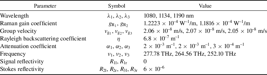
Figure 3(a) illustrates the longitudinal power distributions of the signal light and first-order Stokes wave within the fiber core. Numerical results reveal that in multimode fully open cavity random lasers, signal light undergoes gradual conversion into forward- and backward-propagating first-order Stokes components along the fiber. Notably, this power model resolves the evolution of higher-order modes within the first-order Stokes wave and higher-order Stokes components. These low-power contributions are omitted from the figure for clarity.
(a) Longitudinal power distribution of transverse modes within the fiber core. (b) End reflectivity-dependent power evolution dynamics.
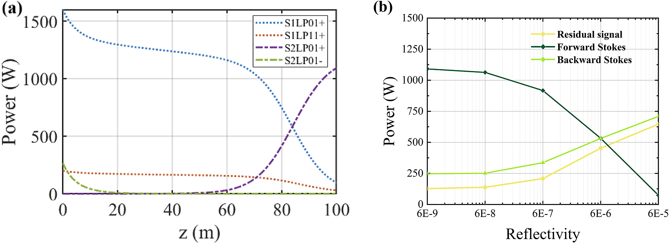
To evaluate end feedback effects on output characteristics, we varied the reflectivity (R 2r) of the first-order Stokes output facet. Figure 3(b) presents the simulated power evolution under varying R 2r values. As R 2r increases from 6 × 10⁻⁹ to 6 × 10⁻⁵, the forward-propagating first-order Stokes power decreases from 1091 to 74 W. Concurrently, the backward-propagating first-order Stokes power increases from 247 to 710 W. Residual signal power exhibits a monotonic growth trend. These results demonstrate that elevated end reflectivity in fully open cavity RRFLs amplifies backward Stokes components via feedback-induced recirculation, thereby reducing forward Stokes output power and overall conversion efficiency. In experiments, the end angle, flatness and cleanliness were precisely engineered to modulate end feedback levels.
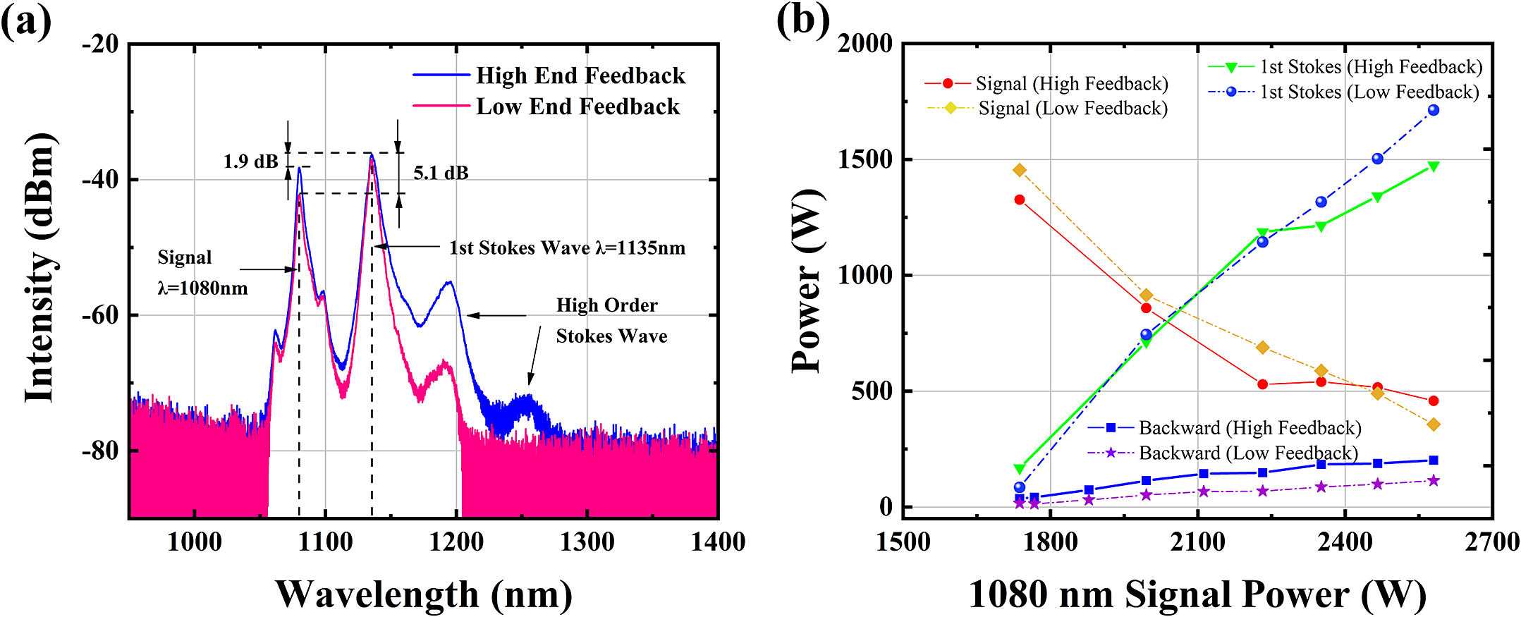
Experimentally, we compared the output power and spectral characteristics of the RRFL employing a 120 m T-GDF under varying end feedback conditions. Figure 4(a) shows the output spectra under different end feedback levels when the signal light power at 1080 nm was 2580 W. High-end feedback was achieved by increasing the cleave angle and reducing end cleanliness, whereas low-end feedback utilized an 8° angled cleave with high surface cleanliness. The spectra primarily consisted of the 1080 nm signal light, the first-order Stokes wave at 1135 nm and higher-order Stokes components. Spectral comparisons revealed that high-end feedback increased the proportion of higher-order Raman waves, thereby reducing the conversion efficiency from the 1080 nm signal light to the first-order Stokes wave. The first-order Stokes wave intensity exceeded the signal light intensity by approximately 1.9 dB under high-end feedback, compared to 5.1 dB under low feedback. This contrast in suppression ratios highlights the important role of end feedback in governing first-order Raman conversion efficiency.
(a) Output spectra of the RRFL under different end feedback conditions with similar 1080 nm power. (b) Power evolution dynamics under varying end feedback.

To quantitatively characterize the feedback effects, Figure 4(b) illustrates the power evolution dynamics. After surpassing the first-order Raman threshold, the residual signal power at 1080 nm decreased progressively with increasing input power. This trend indicates enhanced energy transfer from the signal light to the first-order Stokes wave. Under low-end feedback, both the first-order Stokes wave power and backward-propagating light exhibited gradual amplification compared to high-feedback conditions. At 1080 nm signal input, the first-order Stokes power reached 1475 W (high feedback) versus 1713 W (low feedback), with backward light intensities of 202 and 114 W, respectively. These results demonstrate that low-end feedback in RRFLs suppresses backward Stokes light accumulation while improving first-order Raman efficiency during power scaling. Thus, meticulous management of end feedback is imperative to optimize conversion efficiency and output power in fully open cavity RRFLs.
3.2 Optimization of the T-GDF length achieves 2 kW random Raman laser output
To achieve high-power random Raman laser output and maximize first-order Stokes conversion efficiency, we systematically investigated the output spectra and power evolution of the RRFL with varying T-GDF lengths. The T-GDFs were fabricated with total lengths of 105, 115, 120, 124 and 130 m, corresponding to segmented configurations (narrow-end-tapered section-wide end) of 15-10-80, 25-10-80, 30-10-80, 34-10-80 and 34-10-90 m, respectively. As shown in Figure 5(a), spectral analysis revealed progressive enhancement of Stokes components with increasing narrow-end length from 15 to 34 m. At 34 m narrow-end length, significant higher-order Stokes contributions emerged. The 24 μm core diameter in the narrow end elevated power density, thereby intensifying nonlinear effects. However, excessive nonlinearity reduced the first-order Stokes dominance, necessitating higher-order Stokes suppression for efficiency optimization.
(a) Spectral evolution characteristics across T-GDF lengths. (b) Power and first-order Stokes conversion efficiency evolution.
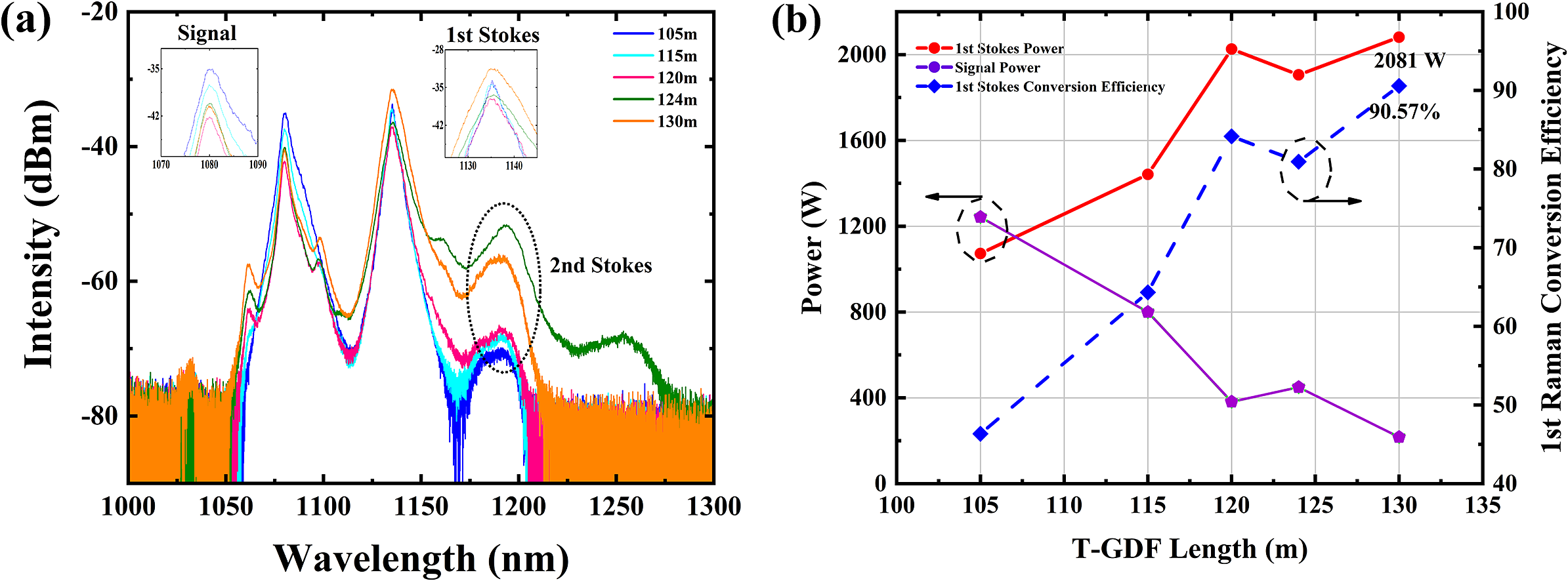
Figure 5(b) presents the power evolution trajectories and first-order Raman conversion efficiency across T-GDF lengths. The first-order Stokes power increased with T-GDF length, peaking at 2026 W for the 30 m narrow-end configuration. Residual 1080 nm signal power exhibited monotonic reduction with extended T-GDF lengths. To further enhance first-order Stokes power and conversion efficiency, we optimized the T-GDF geometry to 30 m at the narrow end and 90 m at the wide end. This design balances mode preservation with higher-order Stokes suppression through tapered mode-field adaptation[ Reference Fedotov, Noronen, Gumenyuk, Ustimchik, Chamorovskii, Golant, Odnoblyudov, Rissanen, Niemi and Filippov 31 ]. The spectral comparison in Figure 5(a) demonstrates effective higher-order Stokes suppression in the 30-10-90 m configuration versus the 34-10-80 m configuration. The 30-10-90 m T-GDF achieved record performance: 90.57% first-order Stokes conversion efficiency and 2081 W output power.
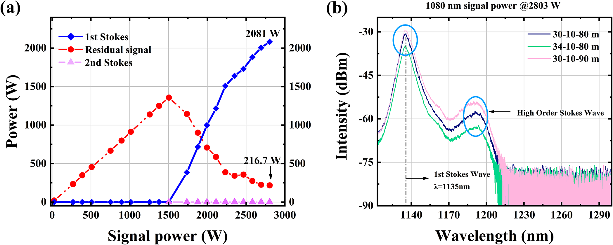
The power evolution curves for the 30-10-90 m segmented T-GDF configuration are shown in Figure 6(a). The first-order Stokes power threshold was measured at approximately 1500 W. Beyond this threshold, the first-order Stokes power increased progressively with rising signal power, while the residual signal power exhibited a monotonic decline. The second-order Stokes power evolution is also presented in the figure. With second-order Stokes power maintained near 0 W, the tailored T-GDF design demonstrated exceptional suppression efficiency, indicating dominant energy conversion to the desired first-order Stokes component. At 2081 W first-order Stokes output, the residual signal power within the RRFL was 216.7 W.
(a) Power evolution curves for the 30-10-90 m T-GDF. (b) Comparative Raman spectra of different lengths.

Comparative Raman spectra of varying tapered configurations are displayed in Figure 6(b). The first-order Stokes emission centered at 1135 nm. Firstly, spectral comparisons were performed with the wide end fixed at 80 m while varying narrow-end lengths. When the narrow-end length was increased from 30 to 34 m, significant reductions in both first-order and second-order Stokes intensities were observed. At 34 m, the first-order Stokes intensity exhibited a 3.8 dB reduction compared to the 30 m configuration. This indicates that beyond a narrow-end length, spectral Stokes components diminish, leading to degraded conversion efficiency. Therefore, the narrow-end length was optimally set at 30 m. Secondly, configurations with a fixed 30 m narrow end and varied wide ends were analyzed. Although the first-order Stokes intensities exhibit minimal variation, the spectral intensity of the 90 m wide-end configuration is marginally higher than that of the 80 m case. This suggests that elongating the wide end of the T-GDF enhances nonlinear interactions. As evidenced by Figure 5(b), extending the wide end preserves modal characteristics, thereby boosting first-order Stokes conversion efficiency and suppressing higher-order Stokes components. Future design optimizations should prioritize strategic enlargement of the wide-end core diameter and length ratio. For instance, increasing the wide-end core diameter from 48 to 50 μm may yield additional Stokes efficiency gains. In prior work, the presence of HOM significantly limited random power enhancement in the fully open cavity. Consequently, we designed the long-tapered fiber with superior mode control capability. In addition, by analyzing the impact of end feedback and further suppressing the feedback of the end to higher-order Stokes, the conversion from a first-order Stokes laser to higher order was restricted. Furthermore, we achieved an output power exceeding 2 kW. This represents the highest recorded power for random fiber lasers to date.
4 Conclusions
In conclusion, through end feedback control and mode management, we achieved 2 kW output in a fully open cavity RRFL pumped by a conventional oscillator, representing the maximum power level reported to date for fully open cavity random lasers. Firstly, we established a multimode random fiber laser theoretical model and numerically analyzed the impact of varying end reflectivity on mode-resolved output power. Experimentally, we compared the differences in the first-order Stokes wave, residual signal and backward-propagating light under distinct feedback conditions. Subsequently, we investigated the spectral evolution across T-GDF lengths and identified the optimal configuration as 30-10-90 m. Finally, we implemented a T-GDF with core/cladding diameters of 24/200–48/400 μm to achieve mode control. At the maximum output power of 2081 W, the first-order Stokes conversion efficiency reached 90.57%. This work provides important guidance for high-power random laser development and investigations of multimode nonlinear effects.
Acknowledgement
This work is supported by the Fund for Distinguished Young Scholars of Hunan (Grant No. 2023JJ10057).


 Open access