Introduction
Components of a miniature radar frontend are a multilayer substrate containing the RX and TX antennas, a highly integrated radar transceiver chip and only a low number of additional devices. This increases the necessity to reduce the size of the multilayer substrate as well as of the antenna structures. Polymer substrates typically used in actual radar frontends have a relative permittivity of ε r ≈ 3. For small antenna designs, it is necessary to use a substrate with a high relative permittivity. Highly integrated radar transceiver devices have excessive power dissipations, so it is necessary to take care about the difference of the thermal coefficients of expansion (TCE) between the semiconductor material and the substrate of the multilayer. Also, the thermal conductivities (TC) of common polymer substrates are very low. A novel substrate should provide in addition low loss and high TC. The TCE should be close to the value of the die material of the radar transceiver device to avoid stress on solder joints due to temperature variations. The RF360 low loss non-shrinkage low-temperature cofired ceramic (LTCC) supports all of these requirements simultaneously.
Typical automotive radar sensors, available on the market are divided into two major parts, the signal processing and power supply unit and the RF frontend, which contains the radar transceiver device and the TX and RX antennas. One typical design is to use one FR4 multilayer board for the signal processing unit and another multilayer board, made of a polymer substrate for the RF frontend.
Another typical design is, to have both units on one multilayer board. Typically those multilayer boards consist of several FR4 layers and one polymer layer, especially for the TX and RX antenna structures on one side of the multilayer board. This board technology leads to typical sensor dimensions of about 75 mm × 55 mm or even larger.
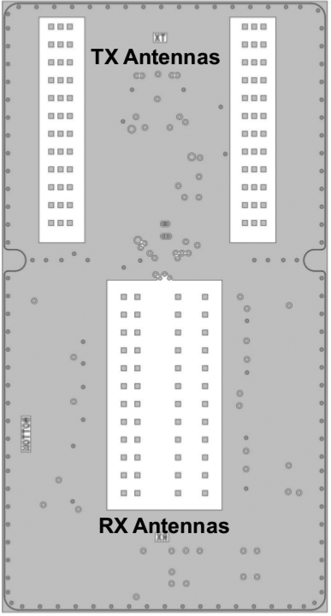
Figure 1 shows the antenna patch layer of a typical radar frontend with two TX antennas and four RX antennas in slot-coupled patch technique based on a polymer substrate. The dimensions of this board lead to a radar sensor with a size of about 90 mm × 55 mm.
Antenna patch layer of a polymer-based radar frontend.
The long-term aimed application is to have a radar sensor for short range applications like radar supported parking and blind spot detection (BSD). Also midrange applications, such as lane change assist (LCA) and cross traffic alert (CTA) could be possible. These applications are addressed by radar sensors mounted in the rear bumper corners, to observe the rear and side area of a vehicle.
The polymer-based radar frontend of a radar sensor close to series production has been replaced by an LTCC miniature frontend. The existing power supply and signal-processing unit as well as the existing software have been reused.
Fully planar and array compatible LTCC antenna element
Antennas for automotive radar sensors need to fulfill many different requirements, depending on the different applications as well as on the frequency range. For example, TX antennas for LCA or CTA need higher gain for mid-range, while TX antennas for BSD need a field of view as large as possible. The RX antennas for all mentioned applications need also a large field of view.
One important requirement for a single antenna element is, to cover the complete frequency range of the automotive radar band from 76 to 81 GHz. Another requirement is to have the size of the antenna element smaller than the substrate wavelength and the feed line should not disturb the radiation.
LTCC substrate with a relative permittivity of ε r ≈ 8 enables much smaller antenna designs. A horn-structured antenna element can be integrated inside a fully planar LTCC multilayer.
Several horn antennas have been presented by other authors. One presentation [Reference Taijima, Song, Yaita, Ajito and Kukutsu1] shows a LTCC horn antenna with an elaborated air cavity inside the horn. A horn antenna, with round structures inside an LTCC multilayer, has been presented [Reference Uchimura and Takenoshita2]. This LTCC horn antenna needs many more layers and can be regarded as single horn antenna. Another antenna design [Reference Han, Lee, Park, Choi, Kim and Lee3] is made of via fences without any horn-like steps. A single antenna with special strip structures covered by via fences also has been presented [Reference Heine, Beer, Ruschund and Zwick4]. This LTCC antenna has been designed for 122 GHz and it is not horn structured.
These antenna structures are larger than a wavelength in the substrate and are mainly designed as single antennas.
Figure 2 shows the layer stack-up with six layers of LTCC substrates as well as a three-dimensional (3D) view of one single antenna element, designed as part of this work. The thickness of one LTCC substrate layer is 110 µm. In the inner layers, the metallization is silver based, for the outer layers, a photolithography-based copper fine line technology was applied, which has an improved structure accuracy compared with etched copper structures on polymer multilayer boards.
3D view of the LTCC antenna element.
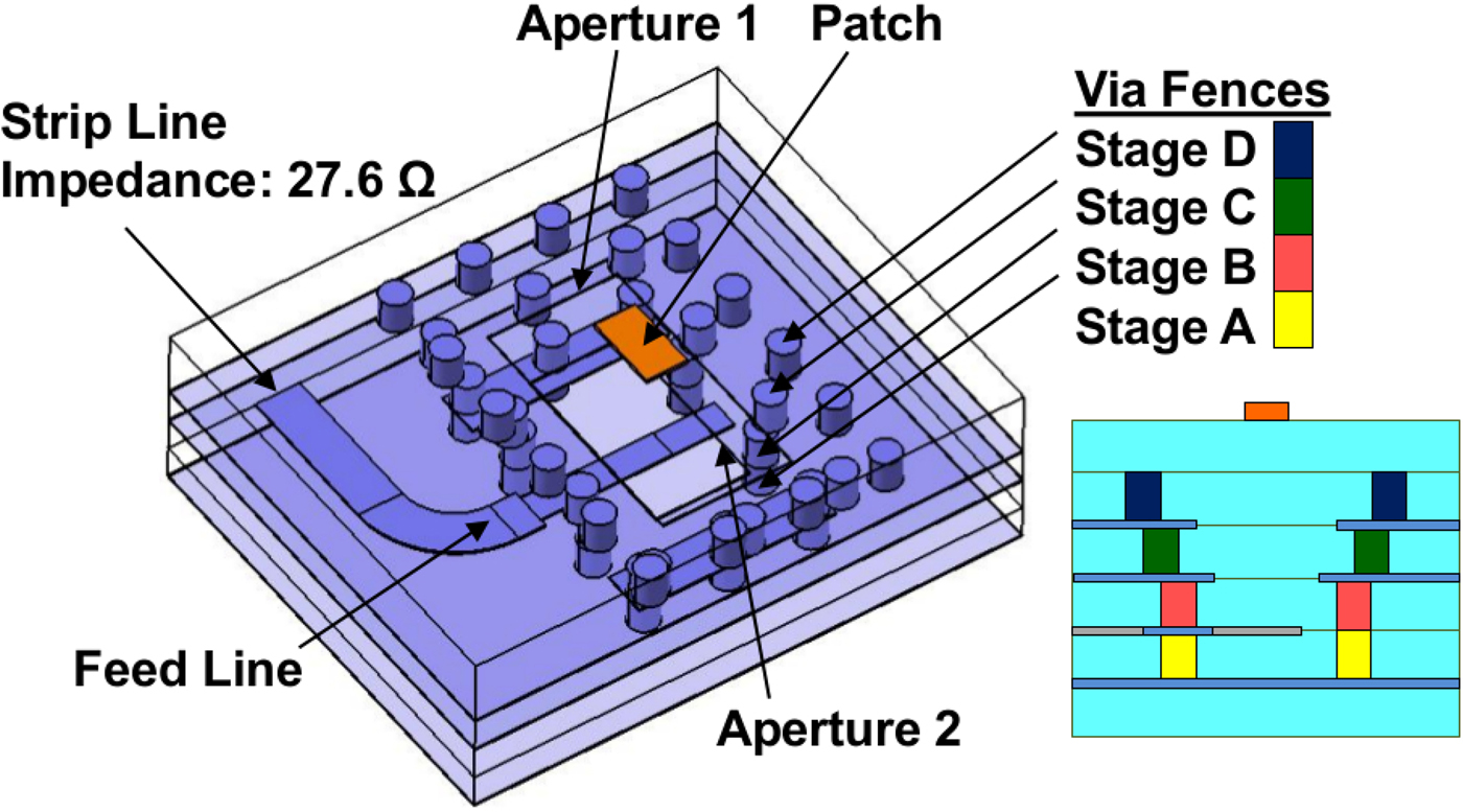
The LTCC antenna element consists of four stages of via fences. Beginning on a ground plane there are two stages of via fences forming a section in which the signal is coupled by a strip line stub.
Two apertures with increasing dimensions from down to top are surrounded by two additional via fences. The structure is similar to a horn antenna [Reference Sickinger and Papziner5].
On the top of the LTCC multilayer, there is a small patch which helps to increase the bandwidth by introducing an additional resonance.
The input impedance of the antenna element is 27.6 Ω, because the width of a 50 Ω impedance strip line wire would be too low for the manufacturing process. The input wire has a 90°-bend [Reference Sickinger and Weissbrodt6]. This bend is necessary for antenna designs with vertical polarization.
The device side needs one additional substrate layer and a second copper fine line layer. One of the most common antennas for automotive radar sensors is patch antennas on the surface of a polymer substrate. A patch element on a polymer substrate, as well as a patch element on LTCC substrate, have been designed for a comparison with the novel horn-structured antenna element. Figure 3 shows the simulation results of gain (G), bandwidth (BW), and the total radiation efficiency, which is defined as η = P rad/P in, where P rad is the radiated power from the antenna and P in is the input power on at the antenna base point.
Comparison of antenna element properties at 79 GHz.
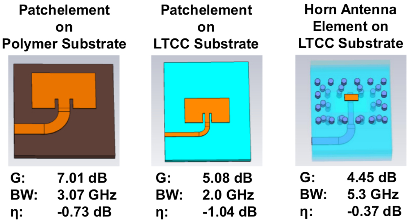
The first antenna element is a patch element on a typical polymer substrate with a total radiation efficiency of η = −0.73 dB. A similar patch element on LTCC substrate has a lower total radiation efficiency around η = −1 dB, due to the higher relative permittivity.
By changing the design to a horn-structured aperture antenna element, the total radiation efficiency increases significantly to η = −0.37 dB. As a consequence, for substrates with higher relative permittivity an aperture antenna design has a higher radiation efficiency than a patch element antenna, where the radiation comes out of the edges.
The bandwidth of the LTCC horn antenna element is also much larger than of the patch designs.
To measure the return loss S 11 of the antenna element with probe contacts, a RF signal transition is necessary. This transition changes the RF signal from a microstrip wire on the surface of the LTCC multilayer to a strip line wire in the inner layer as shown in Fig. 4.
3D view of the RF signal transition.
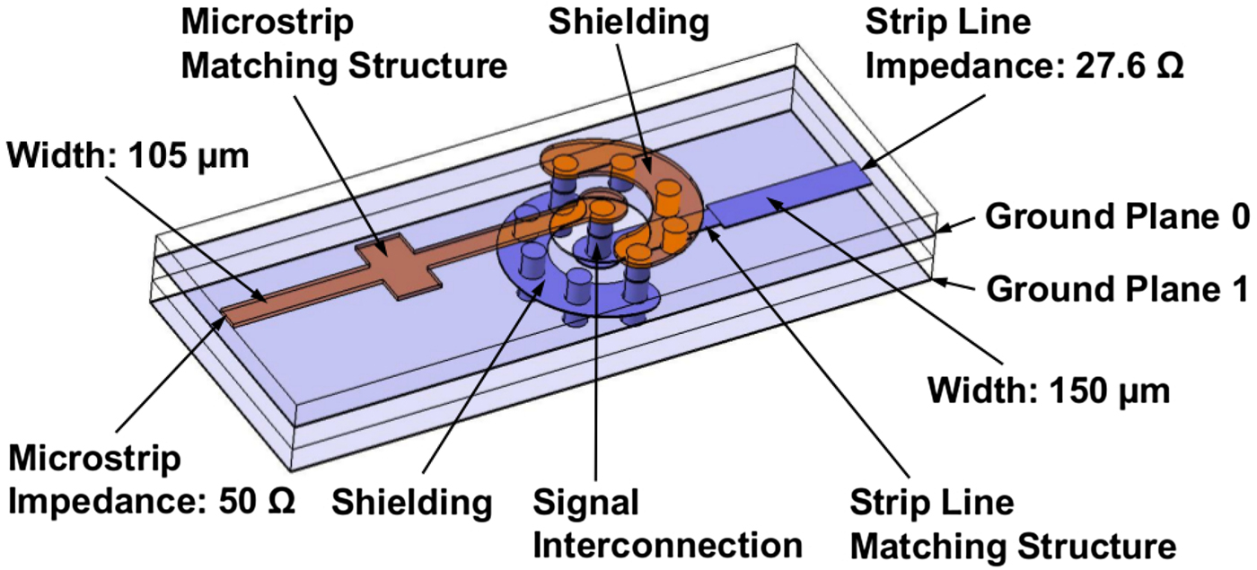
On both ports of the RF signal transition, a matching structure is implemented. The signal via through the layers is shielded by several grounds via, forming a coaxial structure. A comparable structure is described in [Reference Decrossas, Glover, Porter, Cannon, Alan Mantooth and Hamilton7] for a lower frequency and a different substrate.
This transition also includes an impedance matching between 50 Ω microstrip and 27.6 Ω stripline. Simulation and measurement results of the RF signal transition can be found in [Reference Sickinger and Weissbrodt6]. The bandwidth is about 8 GHz and it is sufficient for the automotive radar band. Figure 5 shows the interconnection between RF signal transition and antenna element inside the LTCC multilayer. This is also the configuration when a radar transceiver chip will be placed on the opposite side of the antenna, e.g. a flip chip mounting on the substrate [Reference Hasch, Topak, Schnabel, Zwick, Weigel and Waldschmidt8].
Cross-section view of the LTCC layer stack-up.
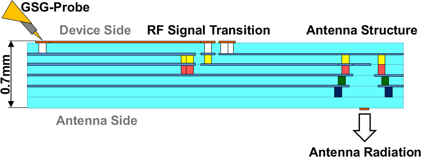
Figure 6 shows the simulated and measured return loss S 11 of the antenna element. The simulated bandwidth at a return loss value of S 11 = −10 dB is BW = 5.3 GHz, so the automotive radar band can be covered by this antenna element. The shape of the return loss S 11 indicates also the second resonance very close to 80 GHz. The simulations have been done with a time-domain solver as well as with a frequency-domain solver.
Return loss simulation and measurement of the LTCC antenna element.
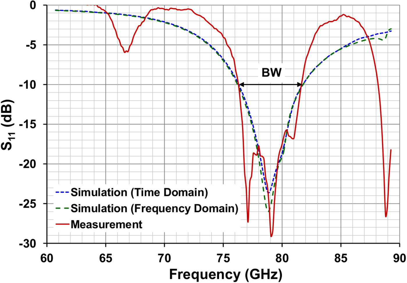
The return loss simulation results as well as the measurement results show a bandwidth of BW = 5.3 GHz. The automotive radar band is also covered by the measurement values. The bandwidth of the LTCC antenna element is also much larger than of the patch designs shown in Fig. 3.
TX antenna design for a short-range radar system
Figure 7 shows the alignment of two LTCC antenna elements for a vertically polarized electrical field  $\vec E$. The dimension of the LTCC antenna element in direction of the electrical field is smaller than one wavelength in strip line structures. So, it is possible to excite both antenna elements in-phase, without any loop ways for the feed network.
Alignment of LTCC antenna elements for vertical polarization.
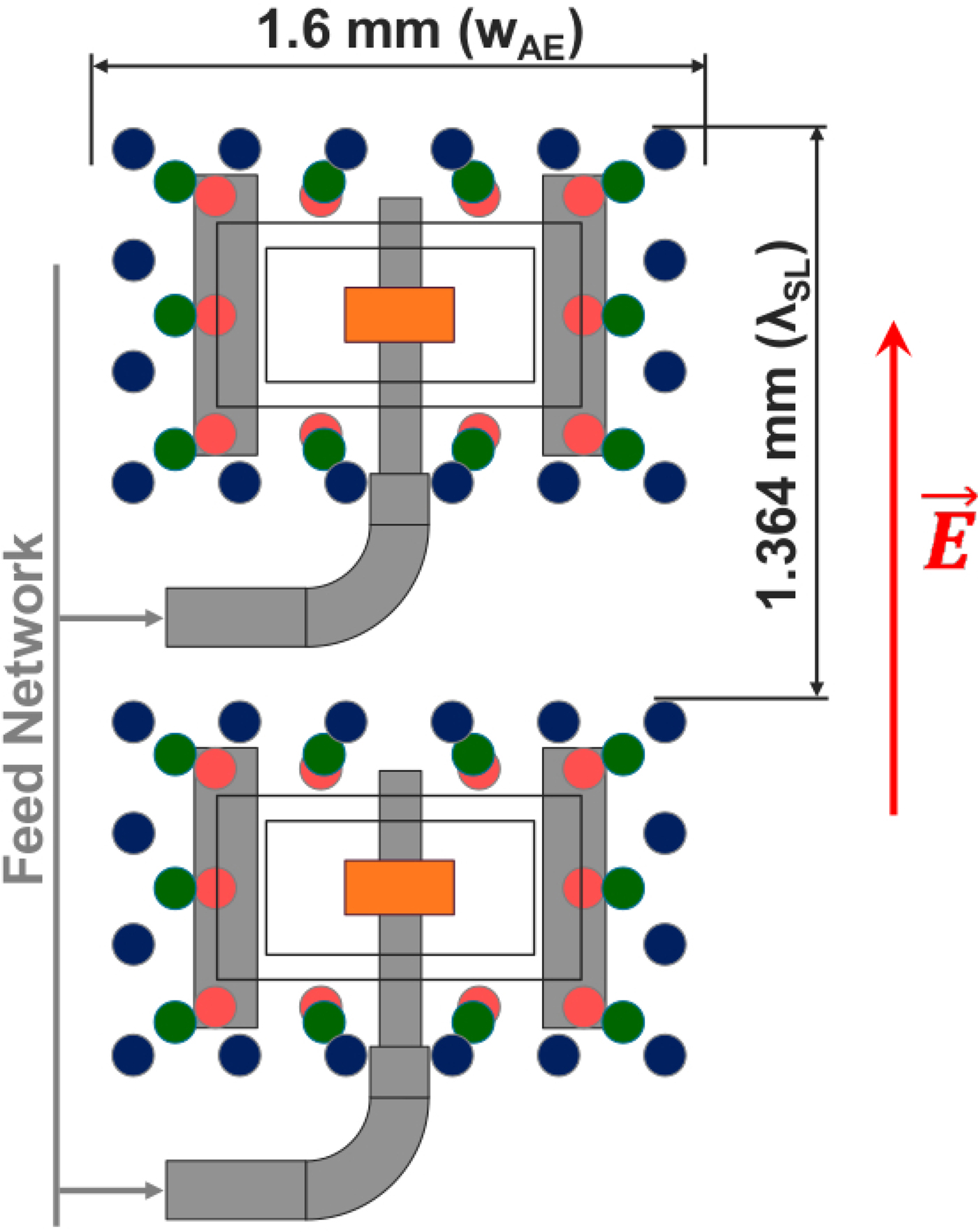
The single LTCC antenna elements can be aligned on a grid with a length of (nλ SL) by (mw AE), where w AE is the width of the LTCC-antenna element including a minimum distance to the next via fence and λ SL the wavelength on strip line wires.
The value of w AE is 1.6 mm for the presented LTCC antenna element.
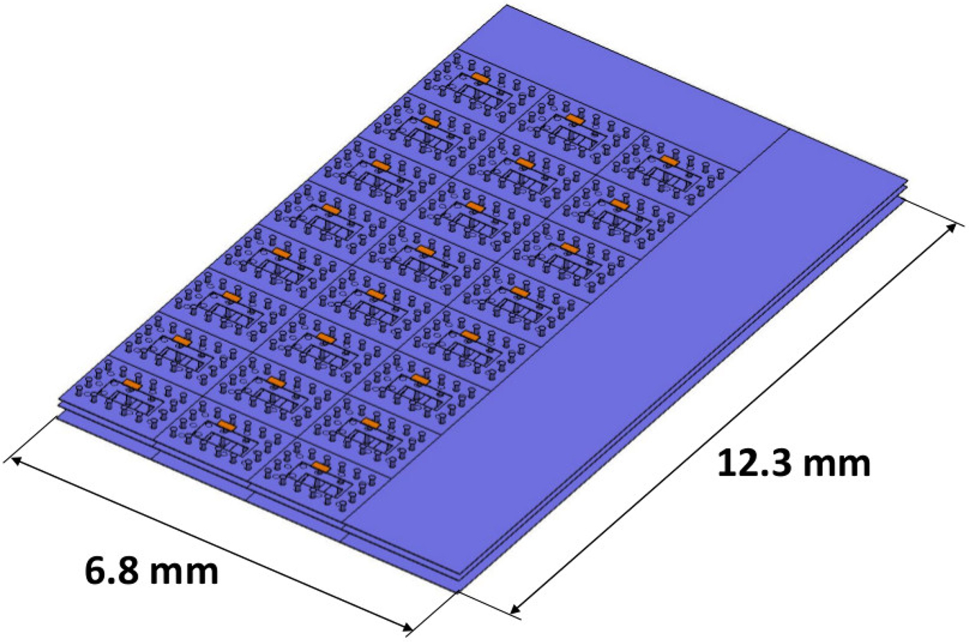
Figure 8 shows the metal layers of an LTCC array antenna. This antenna consists of eight lines with three elements per line and is designed for a radiation pattern, which is perpendicular to the antenna surface. The length of the antenna is 12.3 mm and the width is 6.8 mm. This antenna array has been designed, manufactured, and measured.
3D structure of an LTCC array antenna.
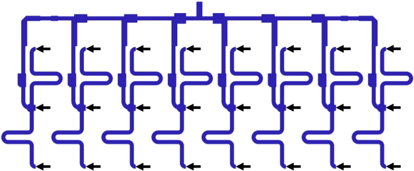
The feed network inside of this antenna is shown in Fig. 9. The input splitter divides the input power to the eight lines, then the power at each line will be divided again by a sub-splitter and delivered to each antenna element. The small arrows indicate the points, where the antenna elements are connected to.
Antenna feed network for eight lines by three antenna elements.
Adapter for antenna radiation pattern measurements
For measurements of the radiation patterns, the antenna structure on the LTCC test multilayer has to be adapted to the E-band converter of an antenna measurement system. Therefore an adapter for the interconnection between LTCC test antenna and WR12 waveguide has been designed at the Institute of Microwaves and Photonics (LHFT) of the University of Erlangen.
Figure 10 shows the front- and the backside of this adapter.
Adapter between WR12 waveguide and LTCC test antenna.
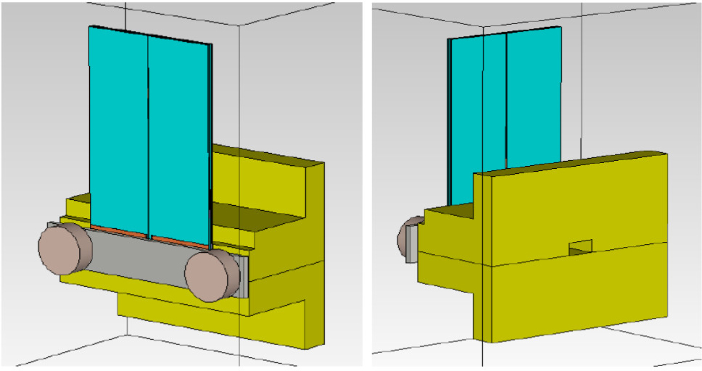
The LTCC test antenna is mounted to the adapter body with a spring and two polymer screws. Covered by the spring, it is fixed by two alignment pins. Therefore two alignment holes have to be drilled into the LTCC test antenna. This can be done by laser or by water ray drilling.
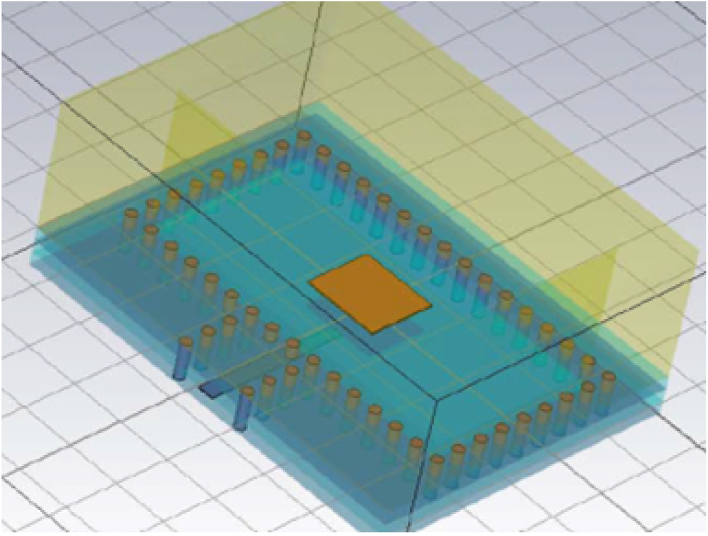
The backside of the LTCC test antenna has a section with two stacked patches to couple a signal into the WR12 waveguide, which is shown in
Figure 11. Both patches are surrounded by via fences. The strip line interface to the antenna structure under test is also shown.
Patch for signal coupling into the waveguide adapter.
The adapter can be connected to the E-band converter of an antenna measurement system.
Characterization of the LTCC to waveguide adapter
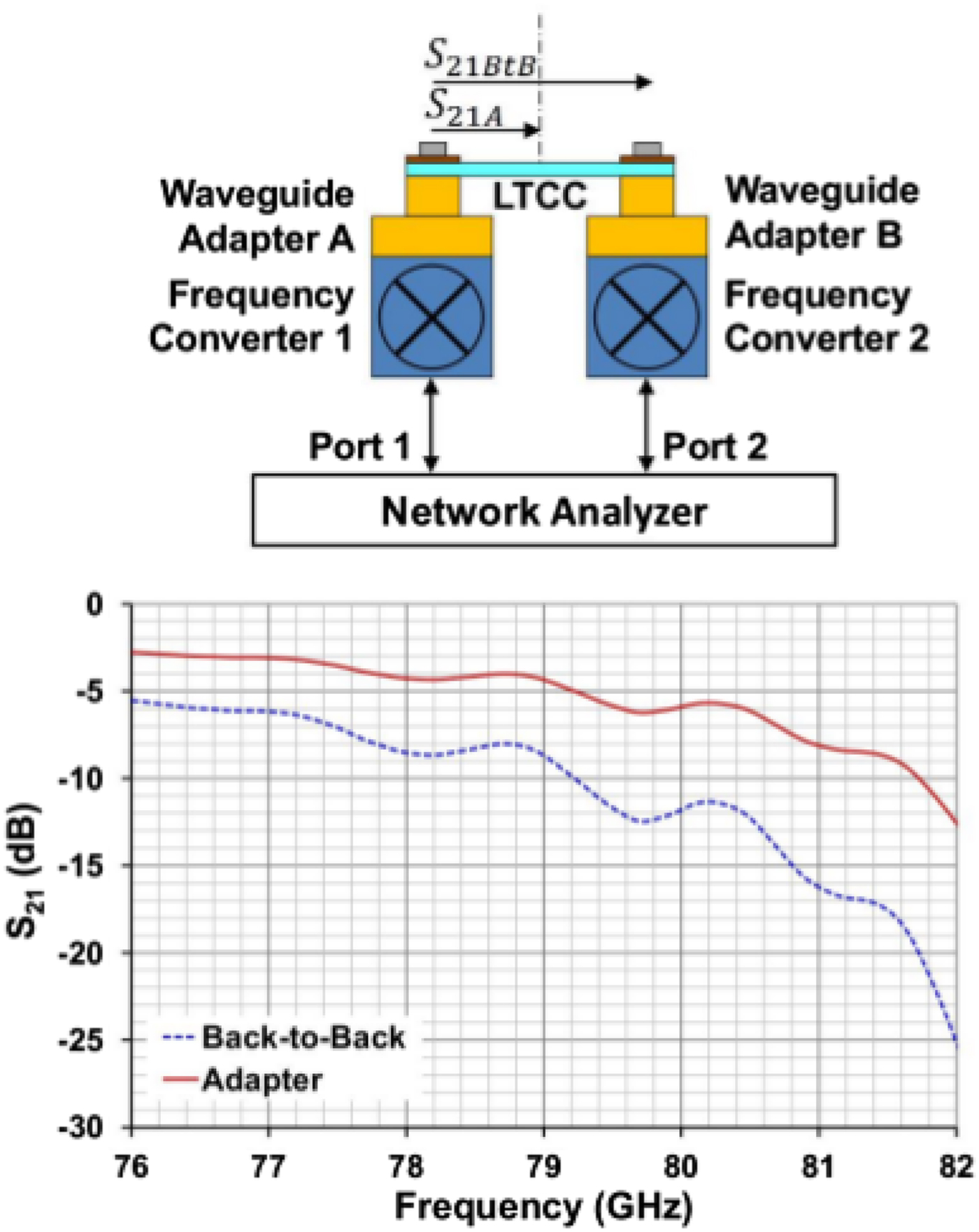
Before the LTCC to waveguide adapters can be used for antenna measurements, they have to be characterized. Therefore a measurement setup with two LTCC to waveguide adapters connected back-to-back using an LTCC multilayer with the adapter structures on both ends and a strip line wire between has been implemented. This LTCC multilayer is totally symmetric, both LTCC to waveguide adapters have identical designs.
Figure 12 shows a setup for insertion loss measurements with a network analyzer. The insertion loss S 21BtB of the back-to-back configuration has been measured with four different parts of the same LTCC multilayer design described above. The mean values of S 21BtB of the four different measurements have been calculated in equation (1).
LTCC to waveguide adapter measurement setup and results.
The network analyzer provides measurement results of S 21BtB touchstone formatted. From the real and imaginary parts of the touchstone values, the mean value of the insertion losses have been calculated for four measurements with different parts of the same LTCC multilayer design:
 $$S_{21_{BtB\_n}} = 20\log \left[ {\displaystyle{1 \over 4}\mathop \sum \limits_{n = 1}^4 \sqrt {Re_{Touchstone}^2 (S_{21BtB\_n} ) + Im_{Touchstone}^2 (S_{21BtB\_n} )}} \right].$$
With the result of the total insertion loss of the back-to-back configuration, the insertion loss S 21A of one LTCC to waveguide adapter including the half-length of the LTCC multilayer can be calculated. With the symmetry of the measurement setup, the insertion loss S 21A of the adapter directly can be given as S 21A = S 21BtB/2 in logarithmic scale.
Figure 12 also shows the insertion losses of the back-to-back configuration as well as the single adapter in a frequency range between 76 and 82 GHz [Reference Köhler9]. For the calibration of the antenna measurement system, the characterized transmission losses of the adapter have to be considered.
A second type of adapter, with a microstrip interface between LTCC multilayer and WR12 waveguide, also is available for measurement of antenna designs including an RF transition from the feed network in a strip line layer to the microstrip layer on the surface.
Antenna pattern simulation and measurement results
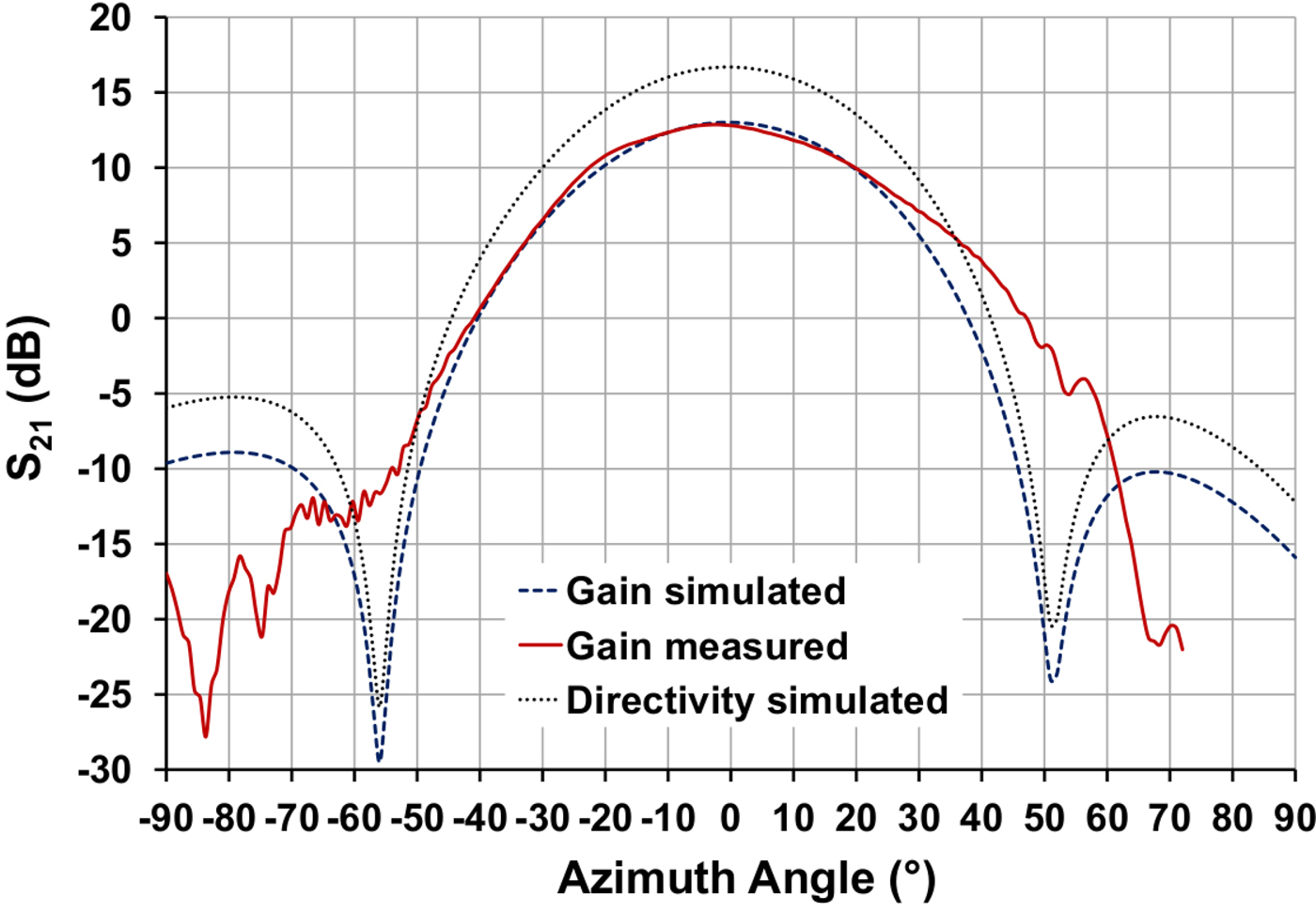
The diagram in Fig. 13 shows the time-domain simulation results as well as the measurement results of the azimuth radiation pattern at a frequency of 79 GHz. For antenna efficiency calculations, the simulation of the directivity is also shown in this diagram. For the antenna pattern simulations, realized gain was the selected plot mode. The simulated and the measured gain of the antenna are around 13 dB and the half-power beamwidth covers a range of 40°. The angular range of the measurement system is from −90° to +70°. Due to some constructive limitations of the measurement setup, the radiation pattern measurement differs from the simulation at angular positions between +30° and +70°.
Azimuth gain and directivity of the array antenna at 79 GHz.
The diagram in Fig. 14 shows the simulated and measured elevation radiation pattern of the presented antenna. The angular range for gain and directivity is from −45° to +45°. The elevation half-power beamwidth is around 20°. The simulated antenna directivity is 3.5 dB above the simulated antenna gain. The radiation efficiency η of the presented array antenna can be calculated with an antenna gain of G = 13.0 dB and an antenna directivity of D = 16.5 dB:
 $$\eta = 10^{G - D/10} \cdot 100{\rm \%} $$
Elevation gain and directivity of the array antenna at 79 GHz.
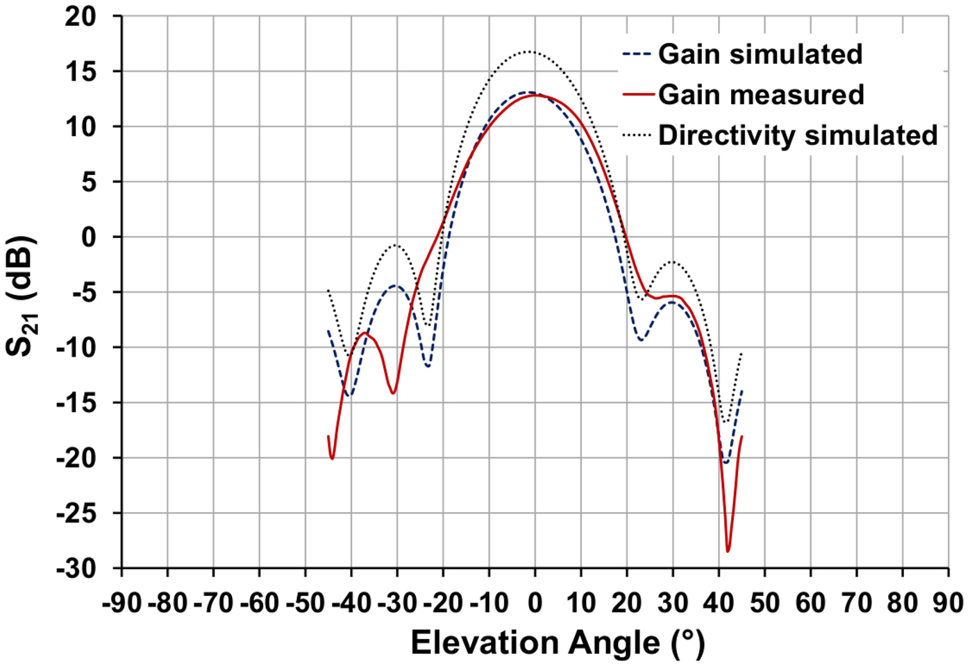
The result is a radiation efficiency of η = 45% for the presented array antenna.
There is a good conformity between measurement and simulation for the azimuth radiation pattern as well as for the elevation radiation pattern.
LTCC miniature frontend
A complete LTCC miniature radar frontend has been designed and manufactured. This frontend has two TX channels, both TX antennas consist of ten lines of antenna elements and three antenna elements per line with vertical polarization. Both TX antennas have a tilt in the azimuth radiation pattern. One TX antenna is radiating in a +30°-direction and the other one is radiating in a −30°-direction referring to boresight direction.
The given LTCC multilayer size of 33 mm × 18 mm for the miniature radar frontend allows slightly larger antennas than the previously presented one. Figure 15 shows one aperture layer of the LTCC miniature frontend.
Aperture layer 1 of the LTCC radar frontend.

The gain of both TX antennas is 13.5 dB and their azimuth half-power beamwidth is about 45°.
The receiver part has four RX channels. The geometrical distance between RX antenna 0 (Ch0) and RX antenna 1 (Ch1) is one free-space wavelength of λ (=3.8 mm). Between RX antenna 1 (Ch1) and RX antenna 2 (Ch2) the geometrical distance is 3λ/2 (=5.7 mm) and between RX antenna 2 (Ch2) and RX antenna 3 (Ch3) the geometrical distance is λ/2 (=1.9 mm). The RX antennas consist of one row of ten antenna elements with vertical polarization. The gain of one RX antenna is 11.5 dB, and the azimuth half-power beamwidth is about 92°.
The elevation half-power beamwidth is about 19° for the TX antennas as well as for the RX antennas. The LTCC miniature frontend uses the presented horn structured antenna design and it is prepared for solder connection to a radar transceiver chip with BGA (ball grid array), which will be the preferred technology in the automotive area.
Another LTCC radar frontend using laminated waveguide fed patch array antennas and a radar transceiver chip, which is connected to the LTCC multilayer by using bond wires is presented in [Reference Wang and Stelzer10]. Also, an LTCC radar frontend using grid array antennas with a laminated waveguide-based feed network is presented in [Reference Bauer, Wang, Menzel and Stelzer11].
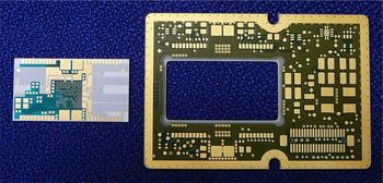
Figure 16 shows the device and the antenna sides of the LTCC miniature radar frontend together with a coin of 2€, the dimension is 33 mm × 18 mm.
Device side and antenna side of the LTCC frontend.
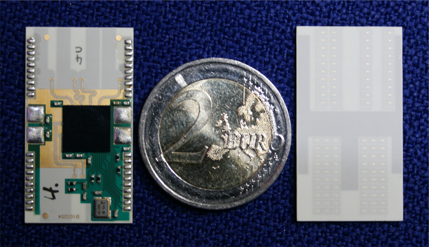
The RF signals on the LTCC miniature radar frontend have to change from a microstrip layer on the surface of the device side to the strip line layer of the antenna feed structure. The shielded RF signal transition has been presented in [Reference Sickinger and Weissbrodt6].
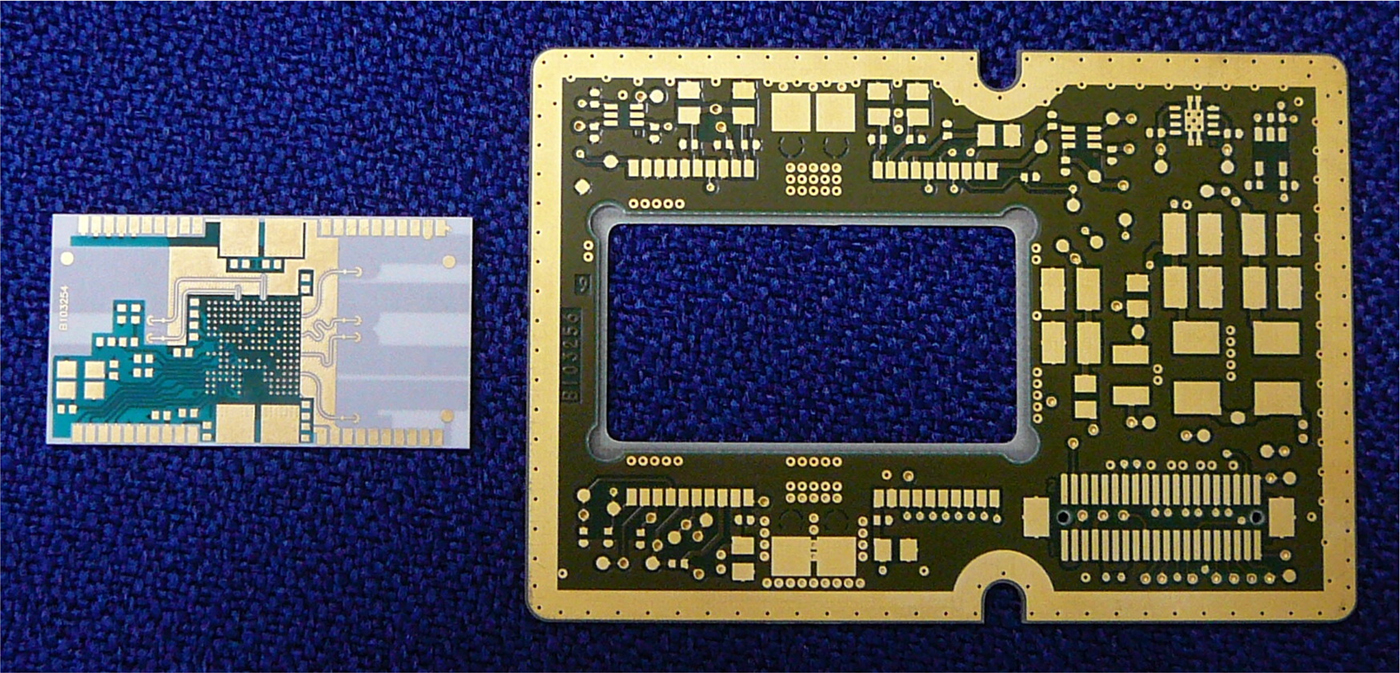
The LTCC miniature radar frontend has been mounted on an adapter board, to connect it to a signal-processing unit. The bare boards of both parts are shown in Fig. 17.
LTCC miniature radar frontend and adapter to signal-processing board.
Sensor measurement results
A radar sensor prototype with LTCC miniature frontend has been manufactured and measured.
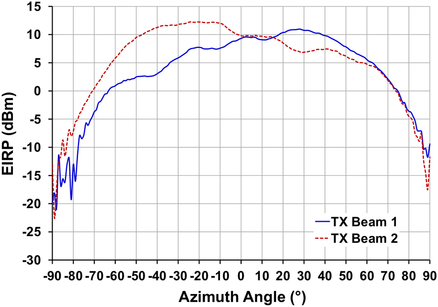
The radiation patterns of both TX antennas have been measured in an anechoic chamber. For this measurement, a power sensor and a horn antenna with a gain of 20 dB have been used. The radar sensor has been mounted on a rotatable fixture at a distance of 0.5 m to the horn antenna.
During TX pattern measurement, the radar sensor has been switched to CW mode (continuous wave). The measured equivalent isotropic radiation power EIRP of the azimuth radiation pattern of both channels is shown in Fig. 18.
Azimuth radiation pattern of both TX channels.
The two-way radiation pattern has been measured by using a 10 dBsm corner reflector at a distance of 4.0 m to the radar sensor. The corner reflector has been detected by the radar sensor, depending on the azimuth angle.
The used mode was 400 MHz FMCW (frequency-modulated continuous wave) at 79 GHz.
The measurement result is transmitted via CAN transceiver.
Figure 19 shows the relative power level of the CAN signals over azimuth angle, while the second TX beam is active. The −10 dB power beam width covers an azimuth angular range of 120° and the −20 dB power beam width covers an azimuth angular range of 140°.
Two-way azimuth radiation pattern of four RX channels.
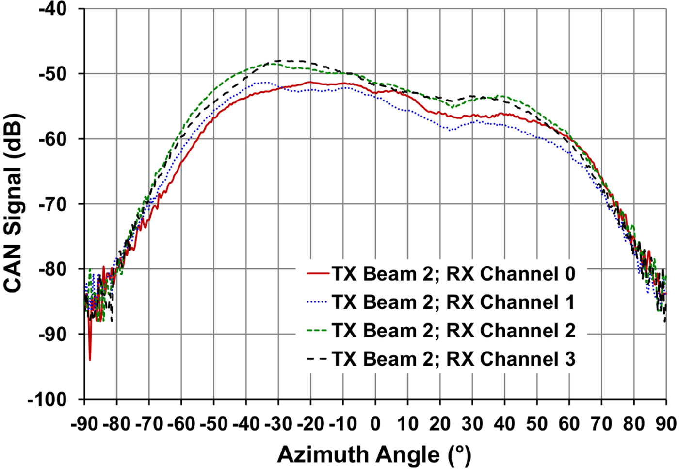
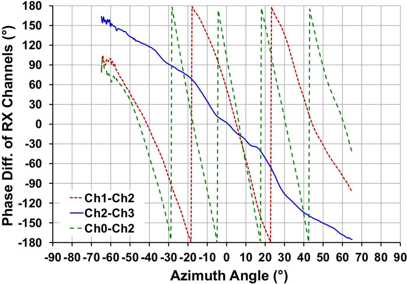
Figure 20 shows the phase difference between several RX channels in the azimuth direction. The phase difference between the two narrowest RX channels (ch2 and ch3) is monotonous and all other phase differences have a very clear shape. Precise detections of angular target positions can be supported very well.
Azimuth phase difference between the RX channels.
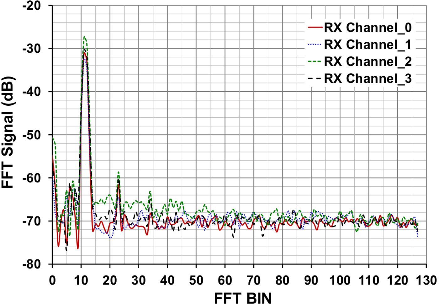
The fast Fourier transform (FFT) spectrum of the radar sensor including the LTCC miniature frontend has been measured in an anechoic chamber by using a corner reflector with a radar cross-section of RCS = 10 dBsm as a target in a distance of 4 m. The FFT spectrum in Fig. 21 is diagrammed up to 127 complex range bins. With a chirp bandwidth of 400 MHz and a number of 256 complex range bins, a distance of 37.5 cm per range bin is established. The distance to the target is represented by range bin 11. A signal-to-noise ratio of SNR = 40 dB is achievable for each channel. The y-axis of the diagram is calibrated to the maximum output power of the A/D converter.
FFT spectrum of a near target.
The short-range area of a vehicle can be observed with a sufficient SNR. A future effort will be an optimization of the RF signal transition between microstrip and strip line as well as the transition from the BGA to the LTCC multilayer. The output power of the used radar transceiver chip as well as the surface plating of the LTCC multilayer will be improved in the future. It is expected, that all these improvements will lead to an LTCC radar frontend which is also sufficient for mid-range applications.
Summary and outlook
In this paper, an antenna element and an array antenna on LTCC substrate have been presented. Miniature frontends, based on LTCC substrate have been manufactured. TX radiation pattern measurements and also pattern measurements of the received signals have been presented.
With an LTCC miniature radar frontend, a new automotive radar system approach is possible. This system could be divided into two major units. A central electrical control unit (ECU) with a connection to several miniaturized sensor units, mounted around a vehicle, is imaginable. These sensors would, besides a housing and a radome, only consist of a miniature frontend together with a circuit which provides a serial data stream between the sensor and the central ECU.
In the long-term view, a sensor with a very small size about 40 mm × 25 mm × 12 mm could be possible, which would be significantly smaller than the previously mentioned sizes of existing radar sensor designs.
This technology could potentially be one solution for parking radar sensors.
Acknowledgements
We would like to thank Institute of Microwaves and Photonics (LHFT) and especially Mike Köhler of the University of Erlangen, Germany for the adapter design and the antenna measurements. Many thanks to K. Aichholzer, Qualcomm Austria RFFE GmbH and his team for the excellent support during the design phase. Also many thanks to T. French, Valeo, Hudson, NH for the layout.
 Frank Sickinger received the Dipl.-Ing. degree in Electrical Engineering and the Dipl.-Kfm. degree in Business Economics from the University of Stuttgart, Germany in 1992 and 1996, respectively. From 1997 to 2008 he was a RF Design Engineer for active microwave components with Bosch-Telecom, Marconi Communications, and Ericsson in Backnang, Germany, where he designed VCOs and frequency synthesizers for wireless access systems in telecommunications. He also investigated distortion analysis of transceiver chains in wireless access systems. In 2008, he joined Valeo Schalter und Sensoren GmbH in Bietigheim-Bissingen, Germany, as a RF Design Engineer for automotive radar antennas. He investigates new antenna designs based on an LTCC substrate in the automotive radar band. Using this antenna technology, he designs miniature radar frontends.
 Ernst Weissbrodt received the Dipl.-Ing. degree in Electrical Engineering and Information Technology from the Karlsruhe Institute of Technology (KIT), Germany, in 2007, and the Dr.-Ing. degree from the University of Stuttgart, Germany, in 2016. During his studies, he spent 6 months with the Alaska Satellite Facility, Fairbanks, AK, USA, where he supported the radar calibration campaign of the Advanced Land Observing Satellite (ALOS). From 2008 to 2012, he was a Scientist with the Fraunhofer Institute for Applied Solid State Physics (IAF), Freiburg, Germany, where he designed and investigated MMICs for applications in millimeter-wave radiometry. In 2013, he joined Valeo Schalter und Sensoren GmbH in Bietigheim-Bissingen, Germany, as a Microwave Design Engineer involved in the field of automotive radar. Dr. Weissbrodt was the recipient of the ARGUS Award 2008 from EADS Defence Electronics, Ulm, Germany, for his diploma thesis on the phase synchronization of the TanDEM-X satellites at the German Aerospace Center (DLR).
 Martin Vossiek received the Ph.D. degree from Ruhr University Bochum, Bochum, Germany, in 1996. In 1996, he joined Siemens Corporate Technology, Munich, Germany, where he was the Head of the Microwave Systems Group from 2000 to 2003. Since 2003, he has been a Full Professor with Clausthal University, Clausthal-Zellerfeld, Germany. Since 2011, he has been the Chair of the Institute of Microwaves and Photonics, University of Erlangen–Nürnberg, Erlangen, Germany. He has authored or co-authored more than 200 papers and his research has led to more than 90 granted patents. His current research interests include radar, microwave sensors, transponder, RF identification, communication, and wireless locating systems. Professor Vossiek has been a member of organizing committees and Technical Program Committees for many international conferences. He is a member of the German IEEE Microwave Theory and Techniques/Antennas and Propagation Chapter Executive Board. He is acting in the German Information Technology Society VDE/ITG in several High-Frequency Technology Specialist Divisions. Martin Vossiek was a recipient of several international awards. He has served on the Review Boards of numerous technical journals. He is a member of the editorial board of the journal Frequenz: Journal of RF-Engineering and Telecommunications. Since 2013, he is an Associate Editor for the IEEE Transactions on Microwave Theory and Techniques.