


1. Introduction
Children with disabilities may find difficulties at the beginning of education in their lives, such as with drawing and writing tasks. Research activities are conducted to discover a way to make it simpler for kids to practice these skills so they can write and draw. In this paper, we propose a novel pyramid-shaped, cable-driven robot with a focus on rehabilitation exercises. The proposed robot specializes in teaching young children drawing and writing skills at primary school. However, the robot is intended also for other related applications such as teaching other preparatory-level skills such as arranging shapes, sorting colors. It can be seen as a useful tool also to assist users who have lost their vision and/or are affected by other illness requiring efforts for regaining drawing/writing skills. Cable-driven parallel robots (CDPRs) are a class of robots that use cables or wires instead of rigid links to transmit forces and motions between the base and the end effector. They have gained significant research attention due to their high payload capacity, large workspace, and ability to achieve high speed and accuracy. They enable movements of e end effector by winding a cable or wire about a drum or winch. They can be used in a variety of applications, including motion simulators, telescope orientation, camera tracking systems, as reported for example in ref. [Reference Gagliardini, Caro, Gouttefarde and Girin1].
The first CDPR, RoBoCrane, was developed in 1989 by the National Institute of Standards and Technology [Reference Albus, Bostelman and Dagalakis2]. Since then, multiple types of CDPRs have been proposed for different applications, including a wheeled robot combined with a cable robot [Reference Korayem, Yousefzadeh and Tourajizadeh3], a CDPR-6DOF for upper and lower extremity mobility [Reference Sheng, Meng, Deng and Xie4, Reference Carbone, Gherman, Ulinici, Vaida and Pisla5], and a CDPR for upper limb rehabilitation [Reference Oyman, Korkut, Yilmaz, Bayraktaroglu and Arslan6, Reference Laribi, Carbone and Zeghloul7]. However, these designs may not fit all motions due to an increased modeling complexity. To address this issue, accurate models are required such as proposed in ref. [Reference Zarebidoki, Dhupia and Xu8]. Examples of cable-driven robots for large workspaces can be found in references [Reference Billel and Abdelouahab9–Reference Wang and Li11]. Moreover, a CDPR can be conveniently applied for high dynamics tasks as outlined in ref. [Reference Hamida, Laribi, Mlika, Romdhane, Zeghloul and Carbone12]. They can be used as motion simulators [Reference Chawla, Pathak, Notash, Samantaray, Li and Sharma13], large-scale telescope orientation [Reference Merlet14], large-scale camera systems [Reference Chawla, Pathak, Notash, Samantaray, Li and Sharma15], and construction [Reference Zhang, Shang, Li and Cong16], to name just a few examples even with applications to industrial scenarios as reported in [Reference Izard, Gouttefarde, Michelin, Tempier and Baradat17–Reference Yuqi, Jinjiang, Ranran, Lei and Lei19]. CDPRs have been successfully implemented also in medical applications such as for assisting post-stroke or paraplegia patients such as reported for example in refs. [Reference Rosati, Gallina, Masiero and Rossi20, Reference Nunes, Rodrigues, Oliveira, Ribeiro, Carvalho and Gonçalves21]. As regards the control of CDPRs, according to ref. [Reference Khosravi and Taghirad22], researchers primarily use PID for low-level control methods. While various control algorithm strategies have been studied by researchers, the PD controller algorithm has been applied to planar cable-based robots, as indicated in refs. [Reference Inel and Khochemane23, Reference Inel and Noor24]. The sliding mode control, as detailed, for instance, in refs. [Reference Alikhani and Vali25, Reference Zaatri and Bouchemal26], has been proposed to enhance the responsiveness and precision of robotic system control to make it more effective. The adaptive sliding mode controller can also be trusted to regulate motor torque and speed to modify the end effector trajectory and enable proper interactions with the intended payload.
This paper is arranged as follows: first, we outline our design approach, then we describe our proposed design solution by developing geometric, kinematic, and dynamic models also based on the formulation in ref. [Reference Carricato27]. After completing the modeling, we describe the main components for a built prototype. Then, we describe our proposed user-friendly interface for operating the built prototype. This proposed user interface implements an adaptative sliding model control strategy that is based on the approach proposed in refs. [Reference Picard, Tahoumi, Plestan, Caro and Claveau28, Reference Schenk, Bülthoff and Masone29]. Finally, we report the outcomes of experimental validation tests along multiple continuous and sinusoidal trajectory tests.
2. The proposed design procedure
This paper aims to demonstrate the engineering feasibility and effectiveness of the proposed design solution for the rehabilitation or exercising on human handwriting. The proposed design approach is summarized in the flowchart that is shown in Fig. 1. The proposed design procedure refers to the general approach that is reported in ref. [Reference Hamida, Laribi, Mlika, Romdhane, Zeghloul and Carbone12]. In particular, this includes a first step consisting of the identification of the design requirements and constraints of the intended handwriting rehabilitation/exercising application. The maximum required workspace is to write on a standard A3 paper with size 297 mm × 420 mm with a maximum vertical motion comparable with a standard pen of 185 mm that is used to perform various discontinuous paths such as needed for example when writing text, in particular, as referring to English alphabet letters. A further requirement is to be able to gently suggest following a path while there is no need to replace the human hand or exerting significant forces.
A flowchart depicting the proposed design procedure.

The next step consists of a topology search for both the robot frame and end effector. It requires identifying the main design choices such as the number of Dofs, actuation, and degree of redundancy. The proposed design solution is further described in Section 3. The next steps consist of identifying all the hardware components to achieve the designed design solution. This includes the mechanical parts that we decided to mostly 3D print for obtaining a first proof of concept. This also includes the selection, development and customization of electronics, control hardware and sensors, whose characteristics are further detailed in Section 4. Afterward, we address the software design including the control loop and the user interface. The proposed software is developed using a combination of Matlab and LabVIEW to achieve a user-friendly graphical user interface that can manage the control models that have been developed as reported in Section 5. The last step of the proposed procedure consists of a validation of the proposed design solution based on both numerical simulations and experimental tests on a built prototype that is available both at University of Skikda and at University of Calabria.
Given the design requirements and intended motion tasks, three degrees of freedom (Dofs) are required consisting of X-Y-Z translations. The two horizontal motions are required to enable the motion of a pen along the writing paper. The vertical motion is required to perform non-continuous writing tasks where the pen needs to be lifted and placed in a different location. This enables the possibility to make complex drawings and eventually replace the pen with different tools and colors. Also, this can allow a wider range of tasks and rehabilitation exercises to be implemented in future.
There are multiple cable topology solutions that can be suitable for the proposed application as also outlined, for example, in the schemes of Fig. 2(a) first case (a) depicts an under-constrained robot with four cables [Reference Inel and Noor24] for three Dofs. Gravity is used in this case to keep the cables in tension, and Fig. 2(b) shows a parallel robot with six cables [Reference Carbone, Gherman, Ulinici, Vaida and Pisla5]. Figure 2(c) describes a cable-driven parallel robot with eight cables [Reference Song, Zhang and Xue30] to provide eight Dofs. Figure 2(d) describes a cable-driven pyramid parallel robot that relies on five motors for controlling the position of the end effector with five Dofs [Reference Khadem, Inel and Carbone31]. It is worth mentioning that cables cannot exert negative tensions since they can only pull and not push. Therefore, an important condition is to maintain a positive cable in tension. This is usually achieved through redundant cables that keep other cables in tension. One should also note that theoretically one can build a pyramid with triangular base and limit the total cables to four. However, this topology would result on a workspace having a triangular shape while the intended specific application requires a square (or rectangular) base shape. Accordingly, a large part of the triangular workspace would not be usable, and a much larger structure size would be required to provide the square workspace that is needed for the specific intended application. Furthermore, a square base simplifies the kinematic modeling also due to symmetry with fully available kinematic models. Thus, we have decided to adopt a pyramid topology with square base.
Distinct types of cable topologies for CDPRs: (a) four cables attached to the top; (b) three cables attached to the top and three cables attached to the bottom; (c) four cables attached to the top and four to the bottom; (d) pyramidal topology.
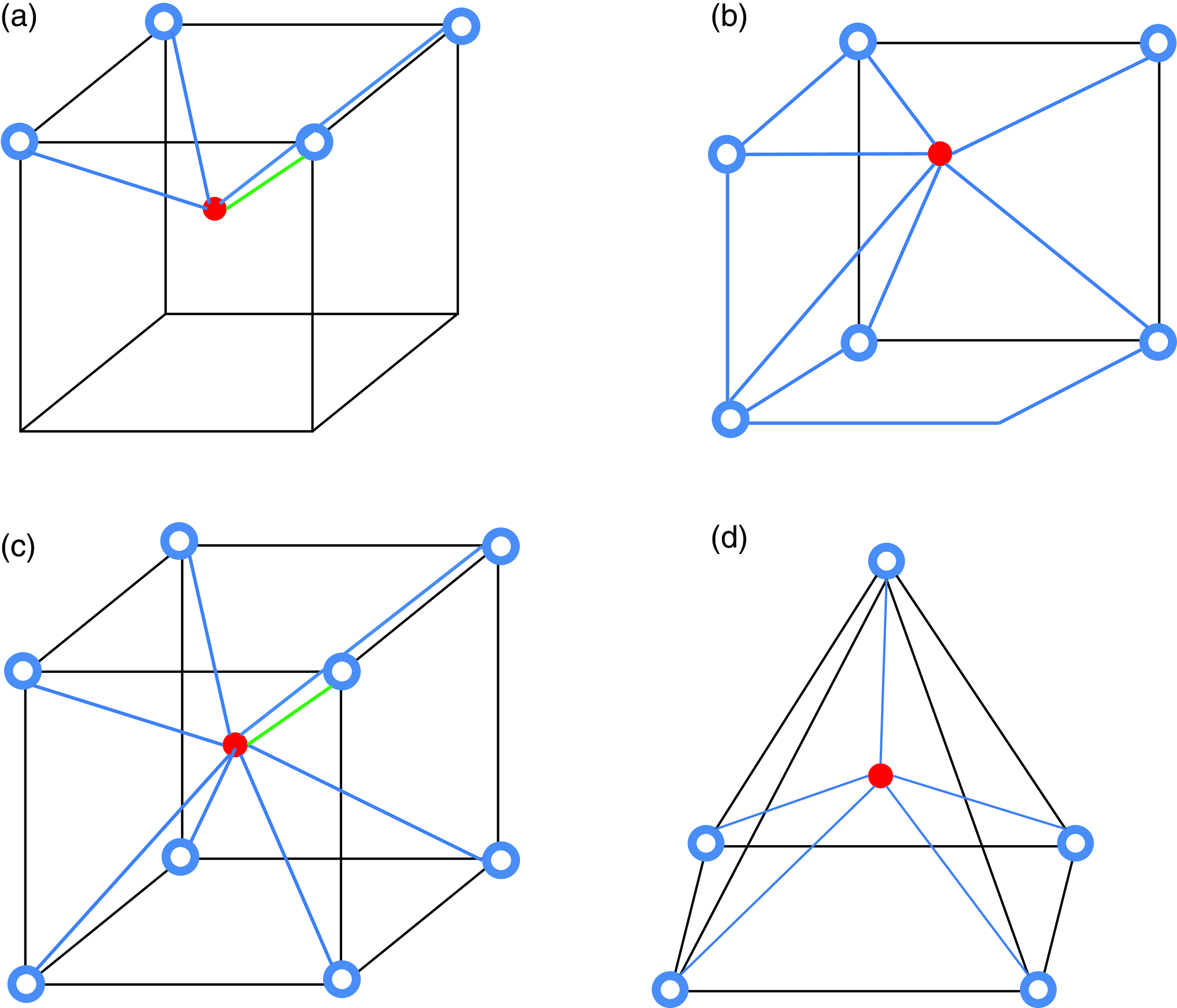
A preliminary analysis was conducted to identify the most convenient topology among those that are presented in Fig. 2 and through this analysis we selected the pyramidal topology in Fig. 2(d). It is worth noting that the minimum set of cables to guarantee the required Dofs is given by four cables, consisting of the three Dofs plus one additional cable for ensuring that each cable is always pulling. Based on this main consideration, we identified the pyramidal shape as the most efficient topology allowing the required three Dofs and motion ranges with a minimum vertical footprint so to make the system easily portable and less bulky.
The proposed solution allows the use of two redundant cables with one ensuring that all cables are pulling in the horizontal plane and one setting the vertical configuration of the end effector. It is worth noting that the proposed solution uses only cables with all motors attached to the fixed frame. This significantly reduces the moving weight and inertia, and it significantly improves the dynamic performance that can be achieved. The proposed solution also avoids using any additional mechanism or actuator for lifting the pen and simplifies the control logic. It is worth noting that the use of highly redundant solutions (i.e., eight cables) has not been considered, since it significantly complicates the control with a negative impact on the attainable accuracy.
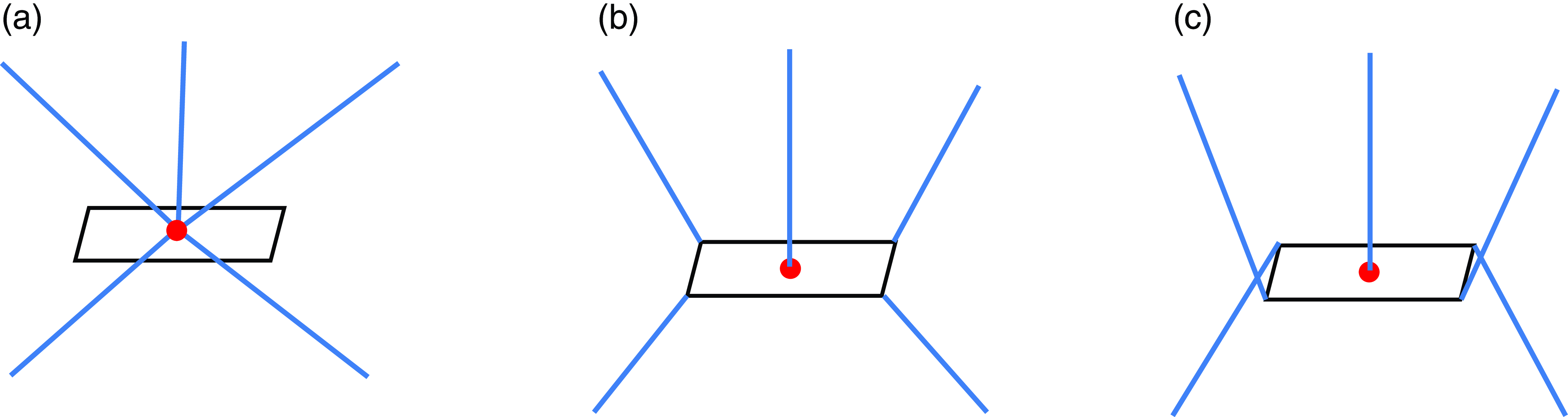
A specific topology search has been conducted also for the attachments of cables to the end effector. Figure 3 represents two distinct types of attachment points for the ends of each cable with the end effector. The first case 3(a) shows the end attachment points of each cable at the center of the end effector. The second case 3(b) shows the cable ends connecting to the vertices and the center of the end effector. The third case 3(c) shows the cable ends connecting to the vertices, which are on the opposite side and the center of the end effector. Through the topological studies we conducted, we identified the solution in Fig. 3(b), since it provides higher distance between the cables and the center of the end effector. Accordingly, this allows to reduce the vibrations that are due to the pen tilting. The solution in Fig. 3(c) has not been considered since it increases the risk of interference of cables.
The next design step consists of the dimensional synthesis where we can identify and optimize the sizes of our proposed design solution. This design process may require iterative loops to identify an optimal solution, as also outlined in ref. [Reference Hamida, Laribi, Mlika, Romdhane, Zeghloul and Carbone12].
Distinct types of attachment for the end effector: (a) all cables attached to the center of the end effector; (b) all cables attached to the edges of the end effector; (c) cables to the edges with cross attachments.
3. The proposed design solution
A specific concept design has been proposed based on the design procedure that has been outlined in the previous section. Figure 4 shows an example of the built prototype.
The proposed prototype robot (CDPR).
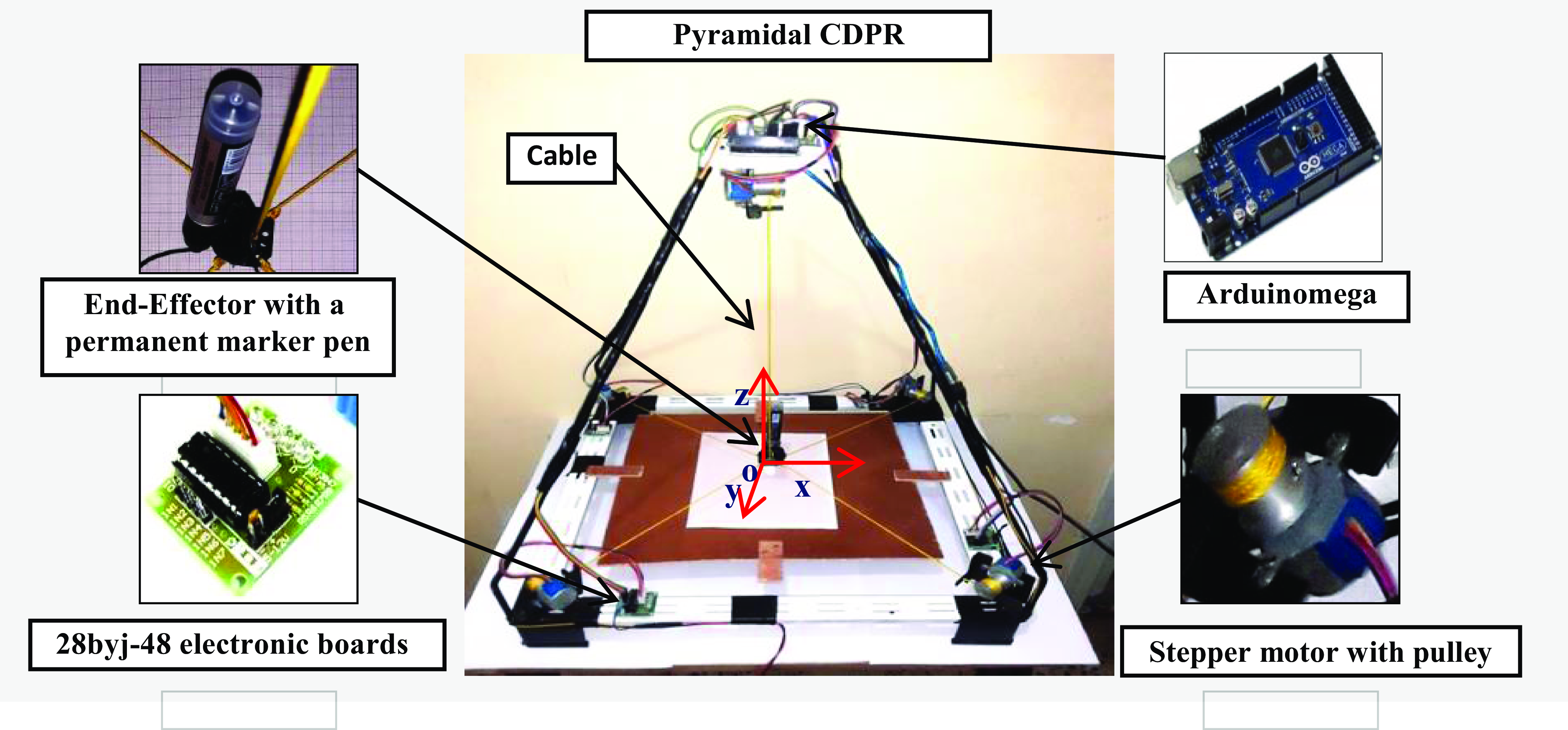
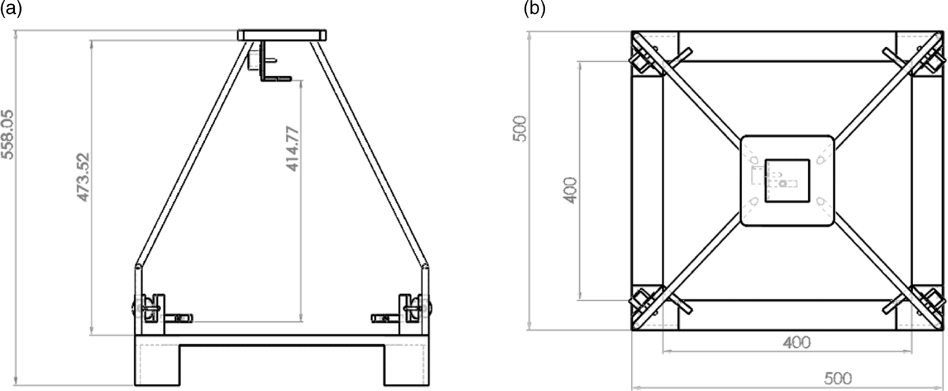
Figure 5(a) and (b) shows the structure general of the pyramidal robot with dimensional geometric (length of the side and height). This robot’s base is square in shape, its length is width is 500 mm × 500 mm, and its height is 558 mm. It can perform all the intended motion tasks that include rehabilitation applications like drawing and writing on a square surface of 400 × 400 mm with a maximum vertical motion of more than 400 mm. This vertical displacement is required for the operation of a standard pen in writing tasks and also for changing the tool for having different pen colors. It is worth noting that the specific end effector is equipped with a pen to perform handwriting tasks. However, the pen tool can be replaced by a gripper and/or camera. This can enable a wide range of additional rehabilitation applications such as assisting a human in pick and place tasks as well as performing common child neurorehabilitation exercises requiring repositioning of objects having various shapes and colors. It can also be used for assisting in arranging shapes, sorting colors, and other applications are required at the preparatory school level as outlined in the 3D cad model proposed in Fig. 6(a) and (b). This robot can write letters, draw geometric trajectories, and execute other beginner-level tasks like classifying shapes and colors, for proving performance that is good and accurate this robot. It can also hold twice the weight of a pen in a child’s hand. The main geometrical parameters of the prototype have been chosen considering the required workspace and the dimensional constraints given by the standard school tables. Also, a maximum payload has been defined as being twice the weight of a standard pen marker resulting in a maximum payload of 400 g. Further optimizations are possible and will be considered in future work.
A 2D CAD model of the proposed robot structure (CDPR): (a) side view; (b) top view.
A 3D CAD model of the proposed robot: (a) operation on a primary school desk; (b) a zoom view during a writing assisting task.

3.1. Geometric model
In this part, we define the geometric and kinematic models for the proposed pyramidal parallel cable-driven robot, and we show the general structure of the robot based on the schemes that are reported in Fig. 7(a) and (b).
where
- $\alpha$
i
: is the rotation about Z axis in the plane (X-Y)
$\alpha$
i
: is the rotation about Z axis in the plane (X-Y) -
$\theta$
i
: is in the plane (X, Y)
-
M i : starting points of the cables on the base frame.
-
k: the side length of the end effector (the shape of the end effector is square);
-
$\vec {\boldsymbol{{P}}}$
i
: vector between points (O, ò) origins of the fixed and movable frame, respectively;
-
$\vec {\boldsymbol{{S}}}$
i
: vector between points (A
i
, M
1);
-
L i : length of the cables;
-
R: the length of the side of the workspace (The shape of the robot base is square);
-
$\vec {\boldsymbol{{d}}}$
i
: vector between points (a, ò);
-
H: the height between the base and motor axes;
-
$\vec {\boldsymbol{{A}}}$
i
: vector between points (O, M
1);
-
$i$
: number of cables.


Schemes of the proposed robot: (a) the geometric model; (b) vector representation of the end effector position.
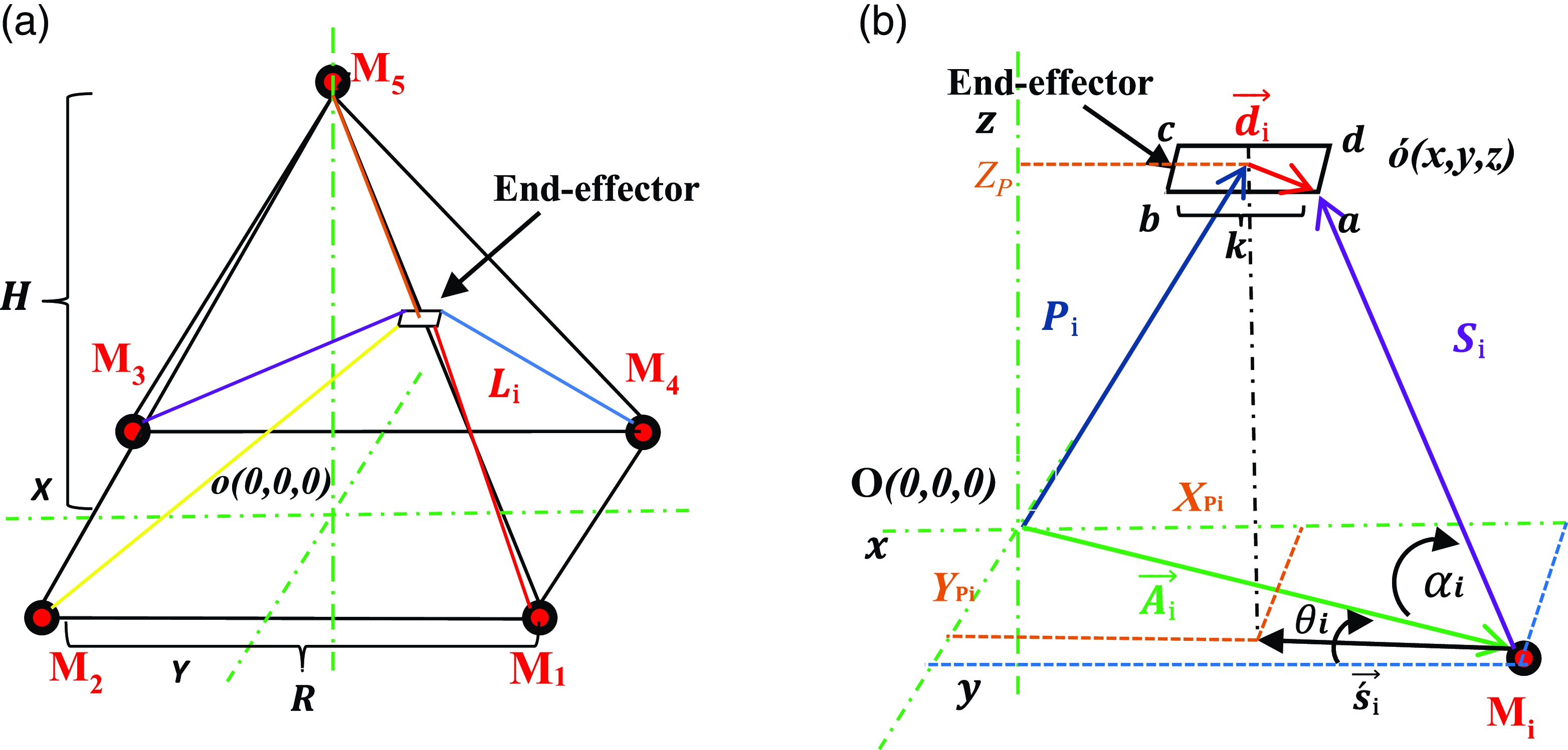
The geometric model of the robot with three Dofs along the (X, Y, and X) axes is defined in this section. Considering what we discussed in [Reference Khadem, Inel and Carbone31], the robot has no rotational motions. This is also due to the selected cable attachments for the end effector (see Fig. 2(b)). Accordingly, no rotations are allowed and the rotation matrix ( $\mathcal{R}^{*}$
) simplifies into an identity matrix in equation (1)
$\mathcal{R}^{*}$
) simplifies into an identity matrix in equation (1)
 \begin{equation}\boldsymbol{{S}}_{\boldsymbol{{i}}}=\boldsymbol{{P}}+\mathcal{R}^{\textbf{*}} \boldsymbol{{d}}_{\boldsymbol{{i}}}-\boldsymbol{{A}}_{\boldsymbol{{i}}}\qquad i=1,\ldots,5\end{equation}
 \begin{equation*}\mathcal{R}^{*}=\left[\begin{array}{c@{\quad}c@{\quad}c} 1 & 0 & 0\\ 0 & 1 & 0\\ 0 & 0 & 1 \end{array}\right]\end{equation*}
The cable lengths L i can be calculated as follows
 \begin{equation}L_{i}=\left\| \boldsymbol{{S}}_{\boldsymbol{{i}}}\right\| =\sqrt{\left(x+d_{i}x_{i}-A_{i}x_{i}\right)^{2}+\left(y+d_{i}y_{i}-A_{i}y_{i}\right)^{2}+(z+{d_{i}}{z_{i}}-{A_{i}}{z_{i}})^{2}}\end{equation}
 \begin{equation}\boldsymbol{{S}}=\left[\boldsymbol{{S}}_{\textbf{1}}\quad\boldsymbol{{S}}_{\textbf{2}}\quad\boldsymbol{{S}}_{\textbf{3}}\quad\boldsymbol{{S}}_{\textbf{4}}\quad\boldsymbol{{S}}_{\textbf{5}}\right]\end{equation}
3.2. Kinematic model
In this section, we describe the inverse and direct kinematic models in the 3D workspace for the proposed robot with five cables.
3.2.1. Inverse kinematic model
The inverse kinematic model for the 3D space is represented with the following equations
 \begin{equation}\left(\!\begin{array}{ccc} &x\\ & y\\ & z \end{array}\right)=\left(\begin{array}{l@{\quad}l} A_{i}x_{i}+L_{i} \cos\! ({\alpha} _{i})\cos\! ({\theta} _{i})\\ A_{i}y_{i}+L_{i} \cos\! ({\alpha} _{i})\sin\! ({\theta} _{i}) \\ A_{i}z_{i}+L_{i}\sin\! {\alpha} _{i} \end{array}\!\right) \quad i=1,\ldots,5\end{equation}
If we derive (x y z) T it with respect to time, we get
 \begin{equation}\left(\!\begin{array}{ccc} &\dot{x}\\ & \dot{y}\\ & \dot{z} \end{array}\right)=\left(\begin{array}{c@{\quad}c@{\quad}c} \cos\! ({\alpha} _{i})\cos\! ({\theta} _{i}) & L_{i}-\sin\! ({\alpha} _{i})\cos\! ({\theta} _{i}) & -L_{i} \cos\! ({\alpha} _{i})\sin\! ({\theta} _{i})\\ \cos\! ({\alpha} _{i})\sin\! ({\theta} _{i}) & L_{i}-\sin\! ({\alpha} _{i})\sin\! ({\theta} _{i}) & L_{i} \cos\! ({\alpha} _{i})\cos\! ({\theta} _{i})\\ \sin\! ({\alpha} _{i}) & L_{i} \cos\! ({\alpha} _{i}) & 0 \end{array}\right)\left(\!\begin{array}{cc} & \begin{array}{c} \dot{L}_{i}\\ \dot{{\alpha} }_{i} \end{array}\\ & \dot{{\theta} }_{i} \end{array}\right) \quad i=1,\ldots,5\end{equation}
where we get the kinematic speed for each cable, as form following:
 \begin{equation}\left(\begin{array}{c} \dot{L}_{1}\\ \dot{L}_{2}\\ \dot{L}_{3}\\ \dot{L}_{4}\\ \dot{L}_{5} \end{array}\right)=\left(\begin{array}{c@{\quad}c@{\quad}c} \cos\! ({\alpha} _{1})\cos\! ({\theta} _{1}) & \cos\! ({\alpha} _{1})\sin\! ({\theta} _{1}) & \sin\! ({\alpha} _{1})\\ \cos\! ({\alpha} _{2})\cos\! ({\theta} _{2}) & \cos\! ({\alpha} _{2})\sin\! ({\theta} _{2}) & \sin\! ({\alpha} _{2})\\ \cos\! ({\alpha} _{3})\cos\! ({\theta} _{3}) & \cos\! ({\alpha} _{3})\sin\! ({\theta} _{3}) & \sin\! ({\alpha} _{3})\\ \cos\! ({\alpha} _{4})\cos\! ({\theta} _{4}) & \cos\! ({\alpha} _{4})\sin\! ({\theta} _{4}) & \sin\! ({\alpha} _{4})\\ \sin\! ({\alpha} _{5})\cos\! ({\theta} _{5}) & \sin\! ({\alpha} _{5})\sin\! ({\theta} _{5}) & \cos\! ({\alpha} _{5}) \end{array}\right)\left(\!\begin{array}{ccc} &\dot{x}\\ & \dot{y}\\ & \dot{z}\end{array}\right)\end{equation}
To obtain the direct kinematic model for the proposed design with five cables, we must invert the equation which gives us $\dot{X}=J^{-1}\dot{L}$
, the solution requires the calculation of the inverse Jacobian matrix J that is not square with dimension (5 by 3). Therefore, to solve this problem, we use the Moore-Penrose pseudo-inverse [Reference Billel and Abdelouahab9],
$\dot{X}=J^{-1}\dot{L}$
, the solution requires the calculation of the inverse Jacobian matrix J that is not square with dimension (5 by 3). Therefore, to solve this problem, we use the Moore-Penrose pseudo-inverse [Reference Billel and Abdelouahab9],
We can write this equation in the form
 \begin{equation}\dot{X}=J^{-1}\dot{L}\end{equation}
where $J^{-1}$
: is the inverse Jacobian matrix. Through the kinematic equations presented in the paper, the speed and acceleration of this robot are controlled considering standard cubic spline interpolations among the predefined target via points.
$J^{-1}$
: is the inverse Jacobian matrix. Through the kinematic equations presented in the paper, the speed and acceleration of this robot are controlled considering standard cubic spline interpolations among the predefined target via points.
3.2.2. Static force analysis
Figure 8 shows the static force-free body model of the end effector with five cables.
A free body model with static forces.

The forces of 3D plane equations are represented in the following equation based on reference [Reference Billel and Abdelouahab9]
 \begin{align}F_{R}=\left(\!\begin{array}{ccc} &f_{x}\\ & f_{y}\\ & f_{z} \end{array}\right) =\left(\begin{array}{c@{\quad}c@{\quad}c@{\quad}c@{\quad}c} \cos\! (\alpha _{1})\cos\! (\theta _{1}) & \cos\! (\alpha _{2})\cos\! (\theta _{2}) & \cos\! (\alpha _{3})\cos\! (\theta _{3}) & \cos\! (\alpha _{4})\cos\! (\theta _{4}) & \sin\! (\alpha _{5})\cos\! (\theta _{5})\\ \cos\! (\alpha _{1})\sin\! (\theta _{1}) & \cos\! (\alpha _{2})\sin\! (\theta _{2}) & \cos\! (\alpha _{3})\sin\! (\theta _{3}) & \cos\! (\alpha _{4})\sin\! (\theta _{4}) & \sin\! (\alpha _{5})\sin\! (\theta _{5})\\ \sin\! (\alpha _{1}) & \sin\! (\alpha _{2}) & \sin\! (\alpha _{3}) & \sin\! (\alpha _{4}) & \cos\! (\alpha _{5}) \end{array}\right)\left(\begin{array}{c} t_{1}\\ t_{2}\\ t_{3}\\ t_{4}\\ t_{5} \end{array}\right)\end{align}
 \begin{equation}S=\left(\begin{array}{c@{\quad}c@{\quad}c@{\quad}c@{\quad}c} \cos\! (\alpha _{1})\cos\! (\theta _{1}) & \cos\! (\alpha _{2})\cos\! (\theta _{2}) & \cos\! (\alpha _{3})\cos\! (\theta _{3}) & \cos\! (\alpha _{4})\cos\! (\theta _{4}) & \sin\! (\alpha _{5})\cos\! (\theta _{5})\\ \cos\! (\alpha _{1})\sin\! (\theta _{1}) & \cos\! (\alpha _{2})\sin\! (\theta _{2}) & \cos\! (\alpha _{3})\sin\! (\theta _{3}) & \cos\! (\alpha _{4})\sin\! (\theta _{4}) & \sin\! (\alpha _{5})\sin\! (\theta _{5})\\ \sin\! (\alpha _{1}) & \sin\! (\alpha _{2}) & \sin\! (\alpha _{3}) & \sin\! (\alpha _{4}) & \cos\! (\alpha _{5}) \end{array}\right)\end{equation}
 \begin{equation}T=\left(\begin{array}{c} t_{1} \\ t_{2} \\ t_{3} \\ t_{4} \\ t_{5} \end{array}\right)=S^{-1}\!\left(\begin{array}{c} fx\\ fy\\ fz \end{array}\right)\end{equation}
The equation (8) is unconstrained, which means that there are infinite solutions to the vector of cable tension T when the force F R is applied. We use the concepts of particulate and homogeneous solution to invert this equation (to express the tensions of the cables T as a function of F R ).
3.3. Dynamic model
3.3.1. Dynamic model of the end effector
In this part, the end effector is expressed by the following expression
 \begin{equation}m \ddot{x}=F_{R}\end{equation}
 \begin{equation}\left(\begin{array}{c@{\quad}c@{\quad}c} m & 0 & 0\\ 0 & m & 0\\ 0 & 0 & m \end{array}\right)\left(\!\begin{array}{ccc} &\ddot{x}\\ & \ddot{y}\\ & \ddot{z} \end{array}\right)=\left(\!\begin{array}{ccc} &F_{Rx}\\ & F_{Ry}\\ & F_{Rz} \end{array}\!\right)\end{equation}
where F R = (F Rx , F Ry, F Rz ) T is the resulting force due to all the cable tensions.
3.3.2. Dynamic model for the system
Here we first apply the kinematic model, and then, we use it for calculating the motor torques starting from
 \begin{equation}L_{i}=\sqrt{(x-A_{i}x_{i})^{2}+(y-A_{i}y_{i})^{2}+(z-A_{i}z_{i})^{2}}\qquad i=1,\ldots,5\end{equation}
 \begin{equation}L_{i0}=\sqrt{(A_{i}x)^{2}+(A_{i}y)^{2}+(A_{i}z)^{2}}\qquad i=1,\ldots,5\end{equation}
with $\theta _{i}=\tan ^{-1}\left(\dfrac{y-A_{i}y_{i}}{x-A_{i}x_{i}}\right)\!;\,\, \alpha _{i}=\tan ^{-1}\left(\dfrac{y-A_{i}z_{i}}{\sqrt{\left(x-A_{i}x_{i}\right)^{2}+\left(y-A_{i}y_{i}\right)}}\right)\!;\,\, \beta =\left(\begin{smallmatrix} \beta _{1}(X)\\[1pt] \beta _{2}(X)\\[1pt] \beta _{3}(X)\\[1pt] \beta _{4}(X)\\[1pt] \beta _{5}(X) \end{smallmatrix}\right)=\dfrac{1}{r}\left(\begin{smallmatrix} L_{10}-L_{1}\\[1pt] L_{20}-L_{2}\\[1pt] L_{30}-L_{3}\\[1pt] L_{40}-L_{4}\\[1pt] L_{50}-L_{5} \end{smallmatrix}\right)$
where $\beta_i$
: vector angle of rotation of the ith pulleys (Fig. 9);
$\beta_i$
: vector angle of rotation of the ith pulleys (Fig. 9); $r_i$
: radius of the ith pulley;
$r_i$
: radius of the ith pulley; $\tau_i$
: torque of the ith motor;
$\tau_i$
: torque of the ith motor; $J_i$
: rotational inertia of the ith shaft-pulley system;
$J_i$
: rotational inertia of the ith shaft-pulley system; $c_i$
: viscous damping coefficient of the ith Motor shaft;
$c_i$
: viscous damping coefficient of the ith Motor shaft;
L i0: initial length of the ith cable.
A scheme of the ith pulley.

One should note that our proposed model does not consider forces and torques due to the holding of the pen. This is a safe design measure, since commonly a pen holder will provide positive forces that will be useful to hold the pen on the writing plane. Furthermore, the purpose of our robot is to assist a user by gently pushing his/her hand to follow a specific path. Gravity forces on the hand are balanced by the desk holding the paper with also has low friction. Accordingly, the robot does not have to apply strong forces. The operation with the hand holding a pen usually requires similar forces and torques as compared to the robot motion alone. Given the purpose of this work, only a preliminary validation was required. Accordingly, the proposed experiments implement a simple position control with cubic interpolation profiles. Several factors have been considered as negligible such as all dynamic effects, masses, inertia, friction, cable compliance, and sagging.
4. The proposed hardware and software
4.1. Hardware components
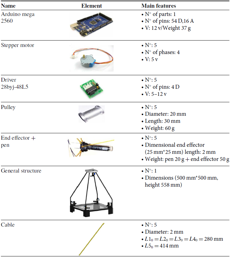
The main hardware components are summarized in Table I. They mostly consist of commercial components that have been selected to fit with the design requirements and adapted to the proposed robot design.
The main selected hardware components for the prototype in Fig. 4.
4.2. The proposed operation logic
The flowchart in Fig. 10 outlines the main operation logic where a graphical user interface GUI is launched on a laptop or tablet device. This
A flowchart for the operation of the proposed robot.

Figure 10 shows a flowchart of the system algorithm. This process takes place in successive stages. X ref, Y ref, and Z ref. They are the values that are entered from the graphical control interface, and UX , UY, and UZ are values after the process that are entered from the graphical interface. We used LabView software as a key component of this project to design the basic control interface, and it is divided into two parts as follows:
-
The upper part sets up the GUI, which defines the Arduino Mega outputs with the 28byj-48 electronic board’s inputs to operate the stepper motors (see Fig. 11);
-
The lower part is the operational part of the system to enter the variables and transfers the end effector from the initial point to the final point (see Fig. 12).
The designed CDPR GUI upper portion (1 – defining the Port (com) to Arduino mega; 2 – define the Arduino mega outputs with the 28byj-48 electronic boards inputs for operating the stepper motors; 3 – the actual motor position).

The CDPR GUI’s lower portion (4 – complex paths are determined by entering a set of via points target coordinates X(x, y, z) into the control interface, and then, the control reads the actual values and performs an interpolation; 5 – entries values (X setpoint, Y setpoint, and Z setpoint) for obtaining point-to-point trajectories; 6 – button for change the trajectory from linear to sinusoidal; 7 – button to change the trajectory Sys 01 or Sys 02 (Sys 01: simple trajectory and Sys 02: complex trajectory); 8 – Dx amplitude along x and Dy amplitude along y for sinusoidal trajectories; 9 – emergency stop; 10 – restart system; 11 – delay timer for moving from the first coordinate point to the second coordinate point in complex paths).

4.3. The proposed control strategy
The proposed sliding mode control strategy is based on the approach in references [Reference Young32, Reference El-Ghazaly, Gouttefarde and Creuze33]. This technique is used with non-linear systems. The aim is to improve the robot’s performance in terms of tracking a desired path. In order to define the sliding mode controller, we have defined the surface of the slider in the 3D space (X-, Y-, and Z-) axes. The sliding surface of a common sliding mode controller has been defined as
 \begin{equation}s_{2dx}=C_{12dx}\! \left(x_{12d}\!\left(t\right)-x_{\textrm{ref}}\right)+C_{22dx} x_{22d}\!\left(t\right)\end{equation}
 \begin{equation}s_{2dy}=C_{12dy}\! \left(x_{22d}\!\left(t\right)-y_{\textrm{ref}}\right)+C_{22dy} x_{42d}\!\left(t\right)\end{equation}
 \begin{equation}s_{2dz}=C_{12dz}\! \left(x_{32d}\!\left(t\right)-z_{\textrm{ref}}\right)+C_{22dz} x_{62d}\!\left(t\right)\end{equation}
where $C_{12dx} ;\, C_{22dx} ;\,C_{12dy} ;\,C_{22dy};\,C_{12dz};\,C_{22dz};\,C_{22dz}$
are parameters to be determined to meet the required tracking performance. The end effector’s trajectory planning parameters are x
ref, y
ref, and z
ref. We used a synthesis method to determine the order of the laws based on [Reference Zaatri and Bouchemal26] so that one can write
$C_{12dx} ;\, C_{22dx} ;\,C_{12dy} ;\,C_{22dy};\,C_{12dz};\,C_{22dz};\,C_{22dz}$
are parameters to be determined to meet the required tracking performance. The end effector’s trajectory planning parameters are x
ref, y
ref, and z
ref. We used a synthesis method to determine the order of the laws based on [Reference Zaatri and Bouchemal26] so that one can write
 \begin{equation}\dot{s}_{2dx}=-K_{2dx}s_{2dx}-Q_{2dx}\text{sign}(s_{2dx})\end{equation}
 \begin{equation}\dot{s}_{2dy}=-K_{2dy}s_{2dy}-Q_{2dy}\text{sign}(s_{2dy})\end{equation}
 \begin{equation}\dot{s}_{2dz}=-K_{2dz}s_{2dz}-Q_{2dz}\text{sign}(s_{2dz})\end{equation}
where K
2dx
, s
2dx
, K
2dy
, s
2y
, $Q_{2dx}$
,
$Q_{2dx}$
, $Q_{2dy}$
,
$Q_{2dy}$
, $Q_{2dz}$
are parameters determined by simulation. for the paths of motion are maintained in the vicinity of a prescribed absorbent sliding surface, through the sign function creates a discontinuous control input resulting from a limited switching around the sliding surface (equal to +1 or −1). We have to implement the control on a non-linear dynamic equation (12), so we have to use the Runge Kutta method because it is suitable for solving non-linear partial differential equations. The overall controller is schematized in Fig. 13 where SM stands for sliding mode. It is worth noting that our proposed model does not take into account the forces and torques resulting from holding the pen. This design decision prioritizes safety, as typically a pen holder would exert positive forces to keep the pen securely on the writing surface. Additionally, our robot’s objective is to assist users by gently guiding their hand along a predetermined path.
$Q_{2dz}$
are parameters determined by simulation. for the paths of motion are maintained in the vicinity of a prescribed absorbent sliding surface, through the sign function creates a discontinuous control input resulting from a limited switching around the sliding surface (equal to +1 or −1). We have to implement the control on a non-linear dynamic equation (12), so we have to use the Runge Kutta method because it is suitable for solving non-linear partial differential equations. The overall controller is schematized in Fig. 13 where SM stands for sliding mode. It is worth noting that our proposed model does not take into account the forces and torques resulting from holding the pen. This design decision prioritizes safety, as typically a pen holder would exert positive forces to keep the pen securely on the writing surface. Additionally, our robot’s objective is to assist users by gently guiding their hand along a predetermined path.
Controller architecture for the proposed robot system.

5. Validation of the proposed robot design
5.1. Simulation of the proposed writing tasks
In this section, we selected a wide range of different trajectories for simulation using Matlab software. We have two trajectories, simple (point-to-point) and complex (continuous trajectories) for drawing letters and geometric shapes as reported in the simulation results in Figs. 14–19 that have been obtained by implementing the models in Section 3. The obtained simulation results confirm the feasibility of the proposed robot design for performing a variety of writing tasks.
Obtained simulation results: (a) plotting a continued triangle trajectory; (b) calculated evolution of cable lengths versus time to achieve the path in (a).

Obtained simulation results: (a) tracking of square trajectories; (b) calculated evolution of cable lengths versus time to achieve the path in (a).

Obtained simulation results: (a) tracking of the circular path; (b) calculated evolution of cable lengths versus time to achieve the path in (a).

Obtained simulation results: (a) tracking of the letter “M” path; (b) calculated evolution of cable lengths versus time to achieve the path in (a).

Obtained simulation results: (a) writing of the letter “N” trajectories; (b) calculated evolution of cable lengths versus time to achieve the path in (a).

Obtained simulation results: (a) tracking of the letter “F” path; (b) calculated evolution of cable lengths versus time to achieve the path in (a).

5.2. Point-to-point experimental tests
Experimental tests have been carried out to validate the proposed simulation models and confirm the feasibility of the writing tasks that have been simulated in the previous section. In particular, Fig. 20 shows the feasibility of point-to-point displacement tests of the end effector from its initial position to the target point.
A point-to-point displacement test of the end effector; (a) initial configuration; (b) final configuration.

5.3. Tests of continuous trajectories
In this section, we present experimental tests that have been carried out by performing the same trajectories that have been simulated in Figs. 14–19. Results of the experimental tests are reported in Figs. 21–26. Comparing the results of simulations and experimental tests one can notice the good tracking of the desired writing paths. This demonstrates the engineering feasibility and effectiveness of the proposed prototype hardware and control approach.
Test drawing a continuous triangle trajectory using the experimental prototype.

Test drawing a continuous square trajectory using the experimental prototype.

Test drawing a circle path using the experimental prototype.

Test drawing the letter “M ” using the experimental prototype.

Test drawing the letter “N” using the experimental prototype.

Test drawing the letter “F” using the experimental prototype.

The obtained results demonstrate the feasibility of the proposed design solution for the intended application. The implemented experimental tests are indeed performed to demonstrate the robot’s functioning and the feasibility of implementing the required writing exercises. An in-depth performance analysis will be performed once a new optimized prototype is built. It is worth noting that the proposed experimental results are only preliminary to provide proof of the proposed concept design. Future work will require the manufacturing of an optimized prototype’s hardware and software. Given the aim of this work, some factors such as pen weight and other inertial effects were neglected in the first tests. Improved tracking accuracy can be obtained by considering the above aspects as well as the friction on the writing paper and the interaction of the pen with the human hand. In future work, we will also implement more accurate dynamic control schemes and quantitatively assess the robot’s accuracy.
6. Conclusions
This paper describes the design process towards a novel cable-driven parallel robot for exercising and rehabilitation of writing and drawing tasks. The proposed design solution has a unique pyramidal structure with a redundant set of five cables to allow tri-dimensional point-to-point or continuous paths. The proposed architecture is very compact with a small footprint that fits primary school or home desks. It is also easily portable and user-friendly. This paper establishes the main geometric, kinematic, and dynamic models of the proposed design solution. Simulations are carried out to validate the feasibility of different exercises. A graphical user interface is proposed based on a combination of LabView and Matlab. This allows accurate position along a wide range of operation tasks by implementing a sliding mode controller enabling complex tri-dimensional trajectories. Experimental tests have been carried out both to validate the proposed simulation models and the engineering feasibility of the proposed robot for the intended tasks. Future work will consist of the manufacturing of optimized hardware and software for the proposed prototype. We will also investigate additional applications for the proposed design.
Author contributions
Conceptualization, M.K., F.I., and G.C.; methodology, M.K., F.I., and G.C.; prototyping and testing, M.K. and A.G.S.T.T.; writing – original draft preparation, M.K., F.I., and G.C.; supervision, F.I. and G.C. All authors have read and agreed to the published version of the manuscript.
Financial support
This paper has been partially funded by the PNRR Next Generation EU “AGE-IT” – CUP H23C22000870006.
Competing interests
None.
Ethical considerations
None.


 Open access

