




I. INTRODUCTION
In the past 30 years, there has been explosive growth in interest in the use of carbon-based nanomaterials, ever since the introduction of 0D (C60 buckminsterfullerene), Reference Kroto, Heath, O’Brien, Curl and Smalley1 1D (carbon nanotubes), Reference Iijima2 and 2D (graphene) Reference Novoselov, Geim, Morozov, Jiang, Zhang, Dubonos, Grigorieva and Firsov3 forms (Fig. 1) of CArbon-based NanO MATerials (CANOMATs), in that chronological order, where D refers to the dimensionality. These low-D CANOMATs are exceptionally advantageous for biomedical applications, because of their unique opto-electronic, chemical, mechanical, and physical properties and their large surface area, Reference Dresselhaus, Dresselhaus and Eklund4–Reference Geim and Novoselov7 coupled with dimensions that are comparable to those of biomolecules such as DNA or proteins. Reference Liu, Tabakman, Welsher and Dai8 For a brief overview of the properties of pristine CANOMATs, the reader is referred to the Supplementary Material. What makes these materials challenging to use is that the protocols for synthesis of carbon nanomaterials result in large dispersion in the purity, yield, and consequently the physico-chemical properties of these materials. Since physiological responses in biological conditions are highly sensitive to uniformity and reproducibility of the material properties, some purification and surface functionalization steps are necessary. Further, to achieve biocompatibility and water solubility, CANOMATs need to be surface-functionalized.
The beauty of carbon. Schematic showing the hexagonal lattice structure of the most common forms of CANOMATs: a semi-infinite sheet of graphene (2D), a single-walled carbon nanotube of (6, 5) chirality (1D), and a C60 bucky ball (0D). The red spheres represent C atoms. Rendered using VESTA. Reference Momma and Izumi155

While there have been many reviews Reference Bakry, Vallant, Najam-ul-Haq, Rainer, Szabo, Huck and Bonn9–Reference Serpell, Kostarelos and Davis23 over the years on the use of CANOMATs for biological applications (focusing on aspects such as biological sensing, imaging, drug delivery, and therapy), to the best of our knowledge, there have been no comprehensive reviews comparing the various strategies for the functionalization of these materials. This is an especially important consideration for early-career scholars and researchers in the materials science community. Although there is great variety Reference Olah, Bucsi, Aniszfeld and Surya Prakash24–Reference Iannazzo, Pistone and Galvagno31 in the availability of functionalization schemes for CANOMATs, young investigators are often faced with the challenging optimization problem of deciding on a technique which is suitable for their particular application, while satisfying the following constraints: (i) agent of functionalization; (ii) number of steps and time required to develop; (iii) the availability of necessary instruments; (iv) the desirability of material properties affected by the functionalization; (v) the scalability of the approach; (vi) reproducibility (both by the originators of the technique, and by subsequent researchers); and (vii) the application space which has already been explored. The details about the parameters used for this Review are listed in the Supplementary Material.
This Review aims to aggregate the various approaches used for functionalization of carbon-based nanomaterials, including chemical and biological functionalization approaches. The parameters used in this Review are discussed in the Supplementary Material. We discuss examples of the Belcher group’s work [Figs. 4(a)–4(c), 7(a), 7(b) and 8(g)] on the use of a biological template (M13 bacteriophage), as a scaffold for noncovalent functionalization of carbon nanotubes for detection of cancers Reference Yi, Ghosh, Ham, Qi, Barone, Strano and Belcher32,Reference Ghosh, Bagley, Na, Birrer, Bhatia and Belcher33 and infectious diseases, Reference Bardhan, Ghosh and Belcher34 and also the use of physical or chemical modification to functionalize graphene oxide (GO) for biosensing applications Reference Chen, Li, Theile, Bardhan, Kumar, Duarte, Maruyama, Rashidfarrokh, Belcher and Ploegh35 involving cell capture from whole blood; using the same metrics described above. The goal of this Review is to provide an objective, quantitative (wherever possible) comparison of these parameters, to help researchers make an informed decision while choosing a functionalization technique for their desired application.
II. FUNCTIONALIZATION OF FULLERENES
A summary of the various techniques of functionalization used for fullerenes is presented in Table 1 in the Supplementary Material.
A. Non-covalent functionalization of fullerenes
Fullerenes are notoriously hard to solubilize in most solvents Reference Ruoff, Tse, Malhotra and Lorents36 (let alone aqueous dispersion). Variations in temperature and pressure are required to solubilize fullerenes. The solubility of C60 shows a maximum in solvents such as CS2, toluene, and hexane at ∼280 K. Given these challenges, it would appear reasonable that most approaches to functionalizing fullerenes have relied on chemical modification through covalent bonding. Nevertheless, there are a few reports of non-covalent functionalization on fullerene molecules.
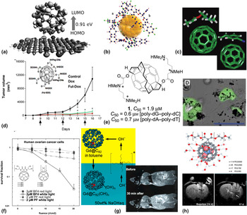
Manna, A.K. et al. Reference Manna and Pati37 have performed first-principle density functional theory (DFT) calculations on the effect of non-covalent interactions of fullerenes (C60, C70, C80 and B80) with single-layer graphene. Their calculations suggest that larger fullerenes result in greater binding strength, facilitated by van der Waals interactions between the adsorbed fullerene and graphene [Fig. 2(a)]. All graphene–fullerene composites displayed perfectly metallic behavior. Besides graphene, several groups of researchers have attempted to form stable polymer composites with fullerenes through non-covalent interactions. For example, Jung, S. et al. Reference Jung, Seo and Shin38 studied the interaction between protonated porphyrin and fullerenes (C60 and C70) in the gas phase, synthesized by electrospray ionization of the porphyrin–fullerene mixture. C70 was shown to bind more strongly than C60, in agreement with the DFT results discussed above. It was rationalized that the protonated porphyrin–fullerene complex is stabilized by π–π interactions. In another manifestation of electron donor–acceptor interactions, Teh, S-L. et al. Reference Teh, Linton, Sumpter and Dadmun39 have demonstrated the dispersion of C60 in a polymer matrix, Fig. 2(c). Subsequently, Li, F. et al. Reference Li, Yager, Dawson, Jiang, Malloy and Qin40 developed polymer/fullerene nanofibers through cooperative non-covalent interaction, by reacting a diblock copolymer derivative of poly(3-hexylthiophene) (P3HT) and phenyl-C61-butyric acid methyl ester (PCBM), with improved performance in organic photovoltaic (OPV) devices. Recently, Reddy, B.K. et al. Reference Reddy, Gadekar and Anand41 studied the crystal structure of fullerenes complexed with antiaromatic isophlorin molecules (a tetra-pyrrolic macrocyclic compound, with a structure similar to porphyrin). They concluded that the complex is stabilized owing to the favored van der Waals interaction of the curved π-surface of the C60 molecule with the nearly planar surface of the anti-aromatic π-surface of the isophlorin molecules [Fig. 2(b)]. Basiuk, V.A. et al. Reference Basiuk and González-Luciano42 reported that upon calculating the binding energies of 20 L-amino acids with C60, they found poor correlation between the binding energies and the scale of hydrophobicity proposed by other research groups. More work needs to be done to understand the mechanism (or possibly a combination of mechanisms) of interaction of the bucky ball with adsorbed molecules.
Covalent and non-covalent functionalization of fullerenes. (a) DFT calculation of the molecular orbital separation between C60 adsorbed on the graphene sheet, indicating stability by van der Waals interactions. (b) Triplet molecular complex of anti-aromatic tetraoxaisophlorin complexed with C60 in a prismatic arrangement. (c) Optimized geometries of C60-polymer composites of DMAEMA or CNSt, resulting from non-covalent electron donor–acceptor interactions. (d) In vivo efficacy of tumor treatment, using fullerene–doxorubicin conjugates, in a melanoma mouse model. Inset shows the structure of the molecule used. (e) 2-handed amphiphilic fullerene, used for the delivery of DNA. Inset shows transfected cells expressing GFP. (f) PDT-mediated killing of ovarian cancer cells, with superior performance of the BF4 fullerene derivative compared to photofrin (PF), a commercial sensitizer. (g) Synthesis procedure for the water-soluble gadofullerenes. Inset shows T 1-weighted MRI, showing strong accumulation in the RES system, at ∼1/20 of the dose of commercial MR contrast agents. (h) Water-soluble, endohedral trimetallic nitride gadofullerenes, functionalized with PEG (top). T 2-weighted MR imaging of brain tumor (bottom panel, white arrow) in rat. See text for definitions of molecules. Reprinted with permissions from: (a and e) Manna and Pati, Reference Manna and Pati37 Nakamura et al. Reference Nakamura, Isobe, Tomita, Sawamura, Jinno and Okayama49 © 2013, 2000 John Wiley and Sons, respectively. (b) Reddy et al. Reference Reddy, Gadekar and Anand41 (c, d, g, and h top) Teh et al., Reference Teh, Linton, Sumpter and Dadmun39 Chaudhuri et al., Reference Chaudhuri, Paraskar, Soni, Mashelkar and Sengupta46 Mikawa et al., Reference Mikawa, Kato, Okumura, Narazaki, Kanazawa, Miwa and Shinohara56 Zhang et al., Reference Zhang, Fatouros, Shu, Reid, Owens, Cai, Gibson, Long, Corwin, Chen and Dorn61 © 2011, 2009, 2001, 2010 American Chemical Society, respectively. (f) Mroz et al. Reference Mroz, Tegos, Gali, Wharton, Sarna and Hamblin53 © 2007 Royal Society of Chemistry. (h, bottom panel) Fatouros et al. Reference Fatouros, Corwin, Chen, Broaddus, Tatum, Kettenmann, Ge, Gibson, Russ, Leonard, Duchamp and Dorn60 © 2006 Radiological Society of North America.

B. Covalent functionalization of fullerenes
Among the first of the CANOMATs to be discovered, fullerene chemistry has been thoroughly investigated and studied. Reference Diederich and Thilgen43 A large number of the functionalization schemes subsequently applied to carbon nanotubes and graphene trace their roots back to the methods used for functionalization of fullerenes.
1. Oxidation and hydroxylation
Fullerenes can also be oxidized with reagents such as OsO4, ozone, oxone monopersulfate, and 3-chloroperoxy benzoic acid, to name a few. In fact, the reaction of OsO4 causes an adduct, C60(OsO4) (4-tert-butylpyridine)2, which breaks the cage structure, and can be detected in x-ray crystallography, which was one of the original confirmations Reference Hawkins, Meyer, Lewis, Loren and Hollander44 used in the determination of the bucky-ball framework. Similarly, poly-hydroxylated derivatives, called “fullerenols” or “fullerols”, C60(OH)8–40 have been synthesized using fullerene reactions with dilute H2SO4 and KNO3, or with dilute NaOH in the presence of H2O2 or other peroxides.
In terms of applications, functionalized fullerenes have been studied extensively for their potential use in drug delivery, photodynamic therapy (reactive oxygen species generation), and in targeted imaging. For example, fullerenol, C60(OH)24 has been shown to protect liver and heart tissue, from the chronic toxicity effects of administering doxorubicin, a chemotherapy agent, in male Wistar rats being treated for colorectal cancer, by Injac, R. et al. Reference Injac, Perse, Cerne, Potocnik, Radic, Govedarica, Djordjevic, Cerar and Strukelj45 Chaudhuri, P. et al. Reference Chaudhuri, Paraskar, Soni, Mashelkar and Sengupta46 have shown that fullerenol complexed with doxorubicin can suppress the proliferation of cancer [Fig. 2(d)] by a G2-M cell cycle block, resulting in apoptosis, with in vivo efficacy comparable to that of the free drug, without the systemic toxicity side effects. Partha, R. et al. Reference Partha, Mitchell, Lyon, Joshi and Conyers47 have formulated “buckysomes”, analogous to liposomes used for the delivery of hydrophobic drugs and other molecules. Amphiphilic fullerene structures embedded with the hydrophobic anticancer drug, paclitaxel (PTX), resulted in in vitro therapeutic efficacy (toward MCF-7 breast cancer cells) comparable to that of a commercial formulation of the drug. Similarly, Liu, J-H. et al. Reference Liu, Cao, Luo, Yang, Lu, Wang, Meziani, Haque, Liu, Lacher and Sun48 have characterized a fullerene–DOX conjugate to be stoichiometrically well-defined, and studied its uptake in MCF-7 cells. They determined that the lipophilic fullerene–DOX conjugate accumulates predominantly in the cytoplasm (unlike free DOX, which proliferates into the nucleus), and may be contributing to cell toxicity through other mechanisms (structural damage to mitochondria, non protein-associated DNA strand break, or the generation of cytotoxic free radical species). Several groups of researchers have attempted to use functionalized fullerenes as gene delivery vehicles. For example, Nakamura, E. et al. Reference Nakamura, Isobe, Tomita, Sawamura, Jinno and Okayama49 synthesized two-handed tetramine-conjugated fullerene, which binds to duplex DNA in a reversible manner, which is internalized into cells by phagocytosis. The efficiency of transfection of a GFP-expression vector [Fig. 2(e)] was determined to be comparable to that of commercial reagents. Building on this approach based on tetramino fullerene, Maeda-Mamiya, R. et al. Reference Maeda-Mamiya, Noiri, Isobe, Nakanishi, Okamoto, Doi, Sugaya, Izumi, Homma and Nakamura50 developed an in vivo gene delivery system to deliver the insulin-2 gene, with consequent reduction in blood glucose levels in a mouse model.
Photodynamic therapy is another active area of research where fullerene derivatives play an important role. For example, Tokayuma, H. et al. Reference Tokuyama, Yamago, Nakamura, Shiraki and Sugiura51 showed that fullerene carboxylic acid, a water-miscible derivative, is biochemically active under low-energy light. As a photosensitive molecule, it was shown to have enhanced cytotoxicity in vitro against HeLa S3 cancer cells, as well as an ability to cleave DNA selectively at the G-sites, in a 182 base-pair fragment. In another approach, Liu, J. et al. Reference Liu, Ohta, Sonoda, Yamada, Yamamoto, Nitta, Murata and Tabata52 have fabricated a photosensitizer with magnetic resonance activity, to enable photodynamic therapy of tumors, by chelating Gd3+ to PEG-functionalized C60. The PDT efficacy of this construct was compared to that of Magnevist, a commercial MRI formulation of gadopentetic acid, in a murine tumor model, and was simultaneously shown to maintain an enhanced MRI signal for a longer duration in tumor tissue. A review of the work done in the area of PDT using fullerene chemistries [Fig. 2(f)] is done by Mroz, P. et al. Reference Mroz, Tegos, Gali, Wharton, Sarna and Hamblin53 One of the main challenges that need to be overcome (in addition to obvious concerns of cytotoxicity, which are discussed in the Supplementary Material) is the absorption maxima of fullerenes being in the UV-blue part of the wavelength spectrum. This limits their use to shallow or sub-surface diseases (most commercial formulations of photosensitizers are activated in the red-IR wavelengths), Reference Dolmans, Fukumura and Jain54 since tissue penetration depth is limited in these wavelength ranges due to very high attenuation Reference Smith, Mancini and Nie55 caused by a combination of autofluorescence, absorption, and scattering mechanisms.
Fullerenes can also be designed to act as MRI contrast agents, in the form of endohedral fullerenes encapsulating the Gd3+ ion inside the fullerene cage (also known as “gadofullerenes”), as pH-responsive imaging probes. The first demonstration of metallofullerenes as in vivo contrast agents was by Mikawa, M. et al., Reference Mikawa, Kato, Okumura, Narazaki, Kanazawa, Miwa and Shinohara56 who synthesized water-soluble, polyhydroxyl forms, Gd@C82(OH)40 [Fig. 2(g)]. Upon i.v. administration into mice at a typical dose of ∼100 µmol Gd/kg, they studied the biodistribution at 24 h, which indicated entrapment of the Gd3+ complex in the reticuloendothelial system (RES) organs, i.e., the lungs, liver, and spleen. This has the benefit of ∼20–100% signal enhancement in these organs in the T 1-weighted mode of MRI, at 30 min post i.v. injection. In subsequent development, Bolskar, R.D. et al. Reference Bolskar, Benedetto, Husebo, Price, Jackson, Wallace, Wilson and Alford57 reported the first water-soluble contrast agent, Gd@C60[C(COOH)2]10 with non-localizing behavior to the RES organs. The carboxylated metallofullerene showed less aggregation compared to the fullerenols, while providing relaxivity similar to commercially available Gd3+-based contrast agents. A comparative study of hydroxyl- and carboxyl-functionalized fullerenes done by Sitharaman, B. et al. Reference Sitharaman, Bolskar, Rusakova and Wilson58 revealed pH-dependent agglomeration, with sizes ∼30–90 nm at pH 9, to hydrodynamic diameters as large as 600–1200 nm at pH 5. In another approach, it was shown possible to encapsulate Gd3+ ions endohedrally by using the “trimetallic nitride template” (TNT) process proposed by Stevenson, S. et al. Reference Stevenson, Rice, Glass, Harich, Cromer, Jordan, Craft, Hadju, Bible, Olmstead, Maitra, Fisher, Balch and Dorn59 Building on this TNT-fullerene approach, Fatouros, P.P. et al., Reference Fatouros, Corwin, Chen, Broaddus, Tatum, Kettenmann, Ge, Gibson, Russ, Leonard, Duchamp and Dorn60 and Zhang, J. et al. Reference Zhang, Fatouros, Shu, Reid, Owens, Cai, Gibson, Long, Corwin, Chen and Dorn61 have shown PEG-functionalized Gd3N@C80[DiPEG5000(OH) x ] to be effective proton relaxation agents for in vivo tumor imaging in the rat brain [Fig. 2(h)]. As a brief footnote, fullerene derivatives have also been explored as contrast agents for X-ray imaging, such as the 2,4,6-triiodinated benzene ring substructure conjugated on to the C60 structure by Wharton, T. and Wilson, L.J. Reference Wharton and Wilson62
III. FUNCTIONALIZATION OF CARBON NANOTUBES
A summary of the various techniques of functionalization used for carbon nanotubes is presented in Table 2 in the Supplementary Material.
A. Non-covalent functionalization of carbon nanotubes
The non-covalent functionalization process has the advantage of improving the solubility of carbon nanotubes significantly, while avoiding modification of the sidewall composition. Therefore, the electronic structure of the carbon nanotubes is not perturbed to a great extent, which preserves the opto-electronic properties of the material, and makes it useful for applications such as sensing and imaging.
1. Small molecule surfactants
This is the most common class of surfactants, or stabilizing agents, used to disperse carbon nanotubes in an aqueous medium. Small-molecule surfactants, such as sodium dodecyl sulfate (SDS) or sodium cholate (SC) are amphiphilic in nature, comprising of a hydrophobic core, and a long hydrophilic tail. When the surfactant molecules are present in the dispersing medium of the CNTs at a concentration higher than the “critical micelle concentration” (CMC), they spontaneously self-assemble into micellar structures, with the hydrophobic core attached to the hydrophobic surface of the carbon nanotubes, and the hydrophilic ends sticking outward, into the aqueous medium, thereby making the wrapped CNTs form a stable suspension in water. Upon sonication, the aggregated bundles of CNTs break apart, which can then further be wrapped with the surfactant molecules, or are eliminated from the suspension during subsequent centrifugation.
The first reported use of small molecule surfactants [Fig. 3(a)] was by O’Connell, M.J. et al., Reference O’Connell, Bachilo, Huffman, Moore, Strano, Haroz, Rialon, Boul, Noon, Kittrell, Ma, Hauge, Weisman and Smalley63 who used 1% SDS to disperse single-walled carbon nanotubes (SWNTs) in H2O. Using this method, they were the first to report bright fluorescence from aqueous-dispersed SWNTs in the second near-infrared window (NIR-II: 900–1600 nm), which makes SWNTs ideally suited for in vivo biomedical imaging applications. Upon measurement of the photoluminescence spectra, they deduced the lifetime to be <2 ns, and a quantum yield ∼10−3, which conclusively suggested a fluorescence emission mechanism from singlet excitons. Following this exciting development, there has been a wide range of other small molecule surfactants reported to have been used for the suspension of carbon nanotubes in hydrophilic environments. Along with SDS, dodecyl-benzene sodium sulfonate (NaDDBS) is also commonly used, due to the high dispersive efficiency of the latter owing to the presence of the benzene ring stacking on to the CNT surface. In general, it is observed that the dispersive power of a surfactant is improved with the magnitude of the charge present on the surfactant molecule, the presence of benzene (or other saturated rings, such as naphthenic groups), or the presence of unsaturated carbon bonds (C=C) in the case of non-ionic surfactants such as Tween-20 or Tween-80. Moore, C.V. et al. Reference Moore, Strano, Haroz, Hauge, Smalley, Schmidt and Talmon64 were among the first to perform a comparative study of the dispersion of SWNTs in various surfactants [Fig. 3(b)], including cetyltrimethylammonium bromide (CTAB), PEO–PPO–PEO triblock copolymer (Pluronic, various molecular weight sizes), Tween and Triton-X. For a comprehensive review of small molecule surfactants [Fig. 3(c)], the reader is referred to Vaisman, L. et al. Reference Vaisman, Wagner and Marom65
Functionalization of SWNTs using small molecule surfactants and PEG derivatives. (a) MD simulation of water and SDS micelle around an SWNT, inset: an individual tube inside a cylindrical micelle. (b) Raman spectra of chirality-resolved SWNTs in various surfactants. (c) Mechanism of SWNT stabilization: cylindrical micelle, hemimicellar or random adsorption of surfactant molecules. (d) Surfactant exchange process, displacing cholate molecules with PL-PEG. This is used for intravital microscopy, with tumor vessel resolution ∼microns. (e) Mixed (50–50%) C18-PMH-mPEG and DSPE-mPEG surfactants to functionalize SWNTs. Inset shows photo of stable suspension. (f) PCA allows spatio-temporal resolution of anatomical organs, after injecting PEG-functionalized SWNT probes similar to (e). (g) Ultrahigh accumulation of C18-PMG-mPEG-coated SWNTs in breast tumor xenograft (∼30% injected dose/g), through the EPR effect. Clearance is mainly through the biliary pathway (feces). (h and i) Dynamic imaging of mouse vasculature, in a model of hindlimb ischemia (h) and cerebral artery occlusion (stroke) (i), using SWNTs similar to (e). (j) Protocols for the preparation of SWNT-based agents (options A, B: ligands, C: radiolabeling, D: siRNA, E: drug loading) for biomedical applications. (k) Example of targeted delivery of a Pt(IV) anticancer drug, using FA conjugated to SWNT-PL-PEG-NH2. See text for definitions. Reprinted (adapted) with permissions from: (a) O’Connell et al. Reference O’Connell, Bachilo, Huffman, Moore, Strano, Haroz, Rialon, Boul, Noon, Kittrell, Ma, Hauge, Weisman and Smalley63 © 2002 American Association for the Advancement of Science. (b, g, and k) Moore et al., Reference Moore, Strano, Haroz, Hauge, Smalley, Schmidt and Talmon64 Robinson et al., Reference Robinson, Hong, Liang, Zhang, Yaghi and Dai72 Dhar et al. Reference Dhar, Liu, Thomale, Dai and Lippard78 © 2003, 2012, 2008 American Chemical Society respectively. (c) Vaisman et al. Reference Vaisman, Wagner and Marom65 © 2006 Elsevier Publishing Group. (d, h, i, and j) Welsher et al., Reference Welsher, Liu, Sherlock, Robinson, Chen, Daranciang and Dai70 Hong et al., Reference Hong, Lee, Robinson, Raaz, Xie, Huang, Cooke and Dai73 Hong et al., Reference Hong, Diao, Chang, Antaris, Chen, Zhang, Zhao, Atochin, Huang, Andreasson, Kuo and Dai76 Liu et al. Reference Liu, Tabakman, Chen and Dai80 © 2009, 2012, 2014, 2009 Nature Publishing Group, respectively. (e) Robinson et al. Reference Robinson, Welsher, Tabakman, Sherlock, Wang, Luong and Dai156 © 2010 Springer. (f) Welsher et al. Reference Welsher, Sherlock and Dai71

2. Poly(ethylene glycol), PEG and its derivatives
PEG and its derivatives have long been used as a molecule of choice for functionalizing nanomaterials Reference Sperling and Parak66 for intracellular drug delivery Reference Cheng, Teply, Sherifi, Sung, Luther, Gu, Levy-Nissenbaum, Radovic-Moreno, Langer and Farokhzad67 and targeted imaging. Reference Dubertret, Skourides, Norris, Noireaux, Brivanlou and Libchaber68 This polymer is useful to render the nanomaterials biocompatible, increase their circulation lifetime in vivo, and to improve uptake and minimize clearance by the RES system, Reference Gref, Lück, Quellec, Marchand, Dellacherie, Harnisch, Blunk and Müller69 i.e., “stealth” properties, because of its similarity to naturally-occurring carriers such as lipoproteins or viruses. Work done by Dai, H. and co-workers has adapted this method to be applicable to the dispersion of carbon nanotubes. One such approach uses a phospholipid-polyethylene glycol (PL-PEG) as a surface-coating agent for the non-covalent functionalization of SWNTs. PL-PEG is an amphiphilic polymer, in which the hydrophobic phospholipid chain sticks to the nanotube sidewall, while the hydrophilic PEG end faces outward, making a strong supramolecular complex in water. One advantage of this functionalization technique is the ability to separate excess PL-PEG molecules from the solution by repeated centrifugation, as the method does not rely on micellar stabilization of SWNTs. In addition, the terminal –NH2 or –COOH groups at the end of the PEG chain allow for the conjugation of targeting agents for specific applications. A drawback of this approach is that the extensive sonication used during the functionalization process leads to significant sidewall damage, resulting in cutting of SWNTs into short segments, ∼50–300 nm. This increases the defect density in the sidewall surface, and makes them less desirable for imaging applications. As an alternative, dialysis of the polymer from the reaction medium (post surface functionalization) can serve as an effective method to remove excess, unreacted PL-PEG.
In the first demonstration of the use of SWNTs as image contrast agents in mice, Welsher, K. et al. Reference Welsher, Liu, Sherlock, Robinson, Chen, Daranciang and Dai70 used a surfactant-exchange method, to displace the organic surfactant, sodium cholate, from the surface of SWNTs, with the PL-PEG polymer (1,2-distearoyl-sn-glycero-3-phosphoethanolamine-N-[methoxy(polyethyleneglycol)], 5 kDa mol wt). At an injected dose of 300 µL of ∼170 µg/mL, they were able to perform high-resolution intravital microscopy imaging of tumor vasculature [Fig. 3(d)] beneath the skin. In further development, Welsher, K. et al. Reference Welsher, Sherlock and Dai71 have applied an image-processing technique called Principal Component Analysis (eigenvector decomposition) to track the whole-body blood circulation [Fig. 3(f)] of injected PL-PEG coated SWNTs. Using this time-resolved technique, coupled with the benefits of NIR-II imaging using SWNTs, they were able to distinguish organ-level anatomical features, by taking into consideration the hemodynamics of injected nanoparticles. Subsequently, Robinson, J.T. et al. Reference Robinson, Hong, Liang, Zhang, Yaghi and Dai72 were able to obtain ultrahigh passive tumor uptake [Fig. 3(g)], ∼30% injected dose/g (using enhanced permeability and retention, or the EPR effect) in a xenograft breast cancer model in mice, through long circulation lifetime (∼20 h) of SWNTs solubilized using poly(maleic anhydride-alt-1-octadecene)-methoxy PEG, C18-PMH-mPEG. In parallel, Hong, G. et al. Reference Hong, Lee, Robinson, Raaz, Xie, Huang, Cooke and Dai73 have used DSPE-mPEG to stably suspend SWNTs in aqueous medium. Using these PEGylated SWNTs, they were able to visualize peripheral arterial disease in a mouse model [Fig. 3(h)], with high spatial (∼30 µm) and temporal (<200 ms per frame) resolution, up to 3 mm depth, which offers ∼3× improvement in spatial resolution compared to micro-CT imaging, without the drawbacks of long exposure (hours) and high radiation doses associated with the latter. It is worth noting here that these PEGylated SWNTs are useful for therapeutic applications, too, beyond the realm of non-invasive imaging. For example, Antaris, A.L. et al. Reference Antaris, Robinson, Yaghi, Hong, Diao, Luong and Dai74 have demonstrated simultaneous tumor imaging and photothermal therapy (PTT), using chirality-separated (6, 5) SWNTs. Upon extension of the vascular imaging technique, Hong, G. et al. Reference Hong, Lee, Jha, Diao, Nakayama, Hou, Doyle, Robinson, Antaris, Dai, Cooke and Huang75 have developed NIR-II fluorescence angiography, to track the regeneration of hind limb non-invasively, post ischemic surgery. Similarly, Hong, G. et al. Reference Hong, Diao, Chang, Antaris, Chen, Zhang, Zhao, Atochin, Huang, Andreasson, Kuo and Dai76 have demonstrated imaging at depths >2 mm in the mouse brain, through the skull, with sub-10 µm resolution. This method has the ability to dynamically observe blood perfusion in the cerebral vessels in real-time, and monitor blood flow during arterial occlusion in a model of cerebral stroke [Fig. 3(i)].
PEGylated carbon nanotubes have also been proven versatile as targeted drug-delivery systems. For example, Liu, Z. et al. Reference Liu, Sun, Nakayama-Ratchford and Dai77 have shown ultrahigh loading capacity of doxorubicin, by π-stacking onto PEG-coated SWNTs, with pH-controlled release. Similarly, Dhar, S. et al. Reference Dhar, Liu, Thomale, Dai and Lippard78 have used amine-functionalized PEG-wrapped SWNTs to deliver folate-conjugated Pt(IV) complex, an anticancer drug [Fig. 3(k)], to selectively destroy FR+ cells. In an in vivo mouse model, Liu, Z. et al. Reference Liu, Chen, Davis, Sherlock, Cao, Chen and Dai79 have shown ∼10× tumor uptake of the water-insoluble drug, PTX, through the application of a SWNT–PTX conjugate, by loading the drug onto the branched PEG chains of the functionalized SWNT through a cleavable ester linkage. There is a wealth of available literature using different variants of this construct for targeted drug-delivery systems. For a thorough primer on the use of PL-PEG conjugation to prepare delivery vehicles (for radiolabels, drugs, image contrast agents, gene or siRNA delivery) based on SWNTs [Fig. 3(j)], the reader is referred to Liu, Z. et al. Reference Liu, Tabakman, Chen and Dai80
3. M13 bacteriophage
Work done in our research group, led by Belcher, A.M. and co-workers, has led to the development of M13 bacteriophage as a multifunctional platform, for synthesizing aqueous-dispersed, actively-targeted SWNTs [Fig. 4(a)], for non-invasively detecting, imaging and monitoring of cancers and infectious diseases in living hosts. M13 is a filamentous, non-lytic bacteriophage, with dimensions ∼880 nm in length and ∼6 nm in diameter. The five capsid proteins (p3, p5, p7, p8, and p9) of the virus can be genetically engineered to display peptides with multiple functionalities, such as targeting motifs against tumor cells (or against bacteria), drug molecules for therapy, or fluorescent probes for imaging. Specifically, our group has functionalized SWNTs longitudinally along M13, through a multivalent, high-copy π–π interaction. This M13-SWNT conjugate maintains sufficiently high fluorescence activity, in aqueous medium and upon in vivo injection into serum, to allow for high-quality NIR-II imaging of living subjects.
Functionalization of SWNTs using M13 bacteriophage and DNA wrapping. (a) M13-functionalized SWNTs. Inset (bottom left) shows probe accumulation in a xenograft prostate tumor (red arrow), using anti-PSMA targeting. (b) M13-SWNT sensor used for detecting bacterial infections, targeted using antibodies labeled on the p3 end. Inset (bottom, center) shows deep-tissue imaging of an endocarditis model of S. aureus infection. Plot (right) shows fluorescence signal enhancement in the targeted case, relative to controls. (c) M13-SWNT probe used for pre-surgical planning, to improve surgical outcome in an orthotopic model of ovarian cancer. Plot (right) shows effectiveness of SWNT-guided procedure (blue bars) in removing a larger fraction of the smaller nodules (≤1 mm size). (d) DNA-wrapped SWNTs. Binding model, with inset showing the “tube within a tube” structure making the SWNT water-soluble. (e) H-bonding interactions between 2 d(GT) n strands form a charge strip (inset, bottom left), which self-assembles around SWNTs depending on their chirality, and used for sorting the nanotubes (absorbance plot). (f) NO implantable inflammation sensor, based on quenching of the SWNT fluorescence. Inset (top left) shows the structure of the DNA oligonucleotide, ds(AAAT)7 with selectivity to NO. (g) Synthesis of SWNTDAP-dex as a reversible sensor for NO detection. (h) “Plant nanobionics”: infiltrating plant leaves with ss(AT)15-SWNT leads to enhanced electron transfer, i.e., augmented photosynthesis. See text for definitions. Reprinted (adapted) with permissions from: (a) Yi et al. Reference Yi, Ghosh, Ham, Qi, Barone, Strano and Belcher32 © 2012 American Chemical Society. (b, d, f, g, and h) Bardhan et al., Reference Bardhan, Ghosh and Belcher34 Zheng et al., Reference Zheng, Jagota, Semke, Diner, Mclean, Lustig, Richardson and Tassi81 Iverson et al., Reference Iverson, Barone, Shandell, Trudel, Sen, Sen, Ivanov, Atolia, Farias, McNicholas, Reuel, Parry, Wogan and Strano89 Kim et al., Reference Kim, Heller, Jin, Barone, Song, Zhang, Trudel, Wogan, Tannenbaum and Strano88 Giraldo et al. Reference Giraldo, Landry, Faltermeier, McNicholas, Iverson, Boghossian, Reuel, Hilmer, Sen, Brew and Strano92 © 2014, 2003, 2013, 2009, 2014 Nature Publishing Group, respectively. (c) Ghosh et al. Reference Ghosh, Bagley, Na, Birrer, Bhatia and Belcher33 (e) Zheng et al. Reference Zheng, Jagota, Strano, Santos, Barone, Chou, Diner, Dresselhaus, Mclean, Onoa, Samsonidze, Semke, Usrey and Walls82 © 2003 American Association for the Advancement of Science.

Yi, H. et al. Reference Yi, Ghosh, Ham, Qi, Barone, Strano and Belcher32 have demonstrated that the M13-functionalized SWNT probes can be detected in deep tissues, up to 2.5 cm in tissue-like phantoms, at very low dosage ∼2 µg/mL. Further, using specific targeting of the prostate-specific membrane antigen (PSMA), they were able to show 4× improvement in uptake of the anti-PSMA-M13-SWNT probe, in a xenograft model of PSMA-positive prostate cancer [Fig. 4(a)]. In further development, Ghosh, D. et al. Reference Ghosh, Bagley, Na, Birrer, Bhatia and Belcher33 have engineered the p3 protein to express a peptide against secreted protein, acidic and rich in cysteine (SPARC), which is overexpressed in aggressive subtypes of ovarian cancer. Using this targeting agent, the SPARC-binding peptide (SBP), the SBP-M13-SWNT probe was used in a pre-surgical planning of cytoreductive surgery in an orthotopic mouse model of human ovarian cancer. With a high target-to-background ratio ∼112, they reported the detection of millimeter-scale tumors [Fig. 4(c)], which should improve “optimal debulking” upon clinical translation of this technology. Simultaneously, Bardhan, N.M. et al. Reference Bardhan, Ghosh and Belcher34 have shown the application of M13-SWNTs for fluorescence imaging of pathogenic infections; at an order-of-magnitude lower dosage compared to other small molecule organic dyes reported in the literature. In an intramuscular model of infection, the authors were able to obtain a ∼3.4× enhancement in the fluorescence signal intensity over background [Fig. 4(b)]. This was made possible by the use of NIR-II imaging with SWNTs, resulting in a lower signal spread, and higher signal amplification compared to shorter-wavelength organic dyes. Further, in a mouse model of endocarditis (infection of the heart valves), they were able to image a ∼5.7× enhancement in the signal intensity. This is an important milestone toward the non-invasive detection of deep-tissue infections, and could go a long way toward management of the problem of the spread of antibiotic-resistant infections in the clinic.
4. DNA wrapping
Several groups have reported the use of single-stranded DNA (ssDNA) for the functionalization of carbon nanotubes. The π–π interaction between the nanotube and the aromatic bases of ssDNA forms a functional complex, with the helical DNA structure extending along the length of the carbon nanotube. In this structure, the nitrogenous bases are attracted to the hydrophobic CNT structure, while the hydrophilic phosphate-sugar moieties face outward, making the complex water soluble, with low toxicity effects. In the first reported use of DNA wrapping, Zheng, M. et al. Reference Zheng, Jagota, Semke, Diner, Mclean, Lustig, Richardson and Tassi81 showed helical wrapping of ssDNA on the surface of SWNTs, supported by molecular modeling [Fig. 4(d)]. Further, it was shown that it is possible to separate fractions of SWNTs based on their electronic structure [Fig. 4(e)], through DNA-wrapping, by chromatographic techniques. A significant advantage of using this method, compared to PEGylation or virus-templated functionalization, is the ability to select Reference Zheng, Jagota, Strano, Santos, Barone, Chou, Diner, Dresselhaus, Mclean, Onoa, Samsonidze, Semke, Usrey and Walls82 and separate Reference Strano, Zheng, Jagota, Onoa, Heller, Barone and Usrey83 the length Reference Huang, Mclean and Zheng84 and chirality Reference Zheng and Semke85,Reference Salem, Landry, Bisker, Ahn, Kruss and Strano86 of the SWNTs based on the sequence of DNA used. It has been shown to be systematically possible to individually sort all the major species of single-chirality SWNTs from a heterogeneous synthesized mixture, by using recognition sequences obtained from employing a randomized DNA library Reference Tu, Manohar, Jagota and Zheng87 with a diversity ∼1060.
Finally, it is worth mentioning a few other non-covalent approaches to SWNT functionalization, although they do not strictly fall into the above categories. Work done by Strano, M.S. and co-workers has focused on the detection of nitric oxide (NO) as a signaling molecule for inflammation. Kim, J-H. et al. Reference Kim, Heller, Jin, Barone, Song, Zhang, Trudel, Wogan, Tannenbaum and Strano88 have designed an optical sensor [Fig. 4(g)] based on the detection of fluorescence modulation of SWNTs in the presence of NO, by wrapping the former with 3,4-diaminophenyl-functionalized dextran (DAP-dex), which only responds to NO but not to other reactive nitrogen or oxygen species. Subsequently, Iverson, N.M. et al. Reference Iverson, Barone, Shandell, Trudel, Sen, Sen, Ivanov, Atolia, Farias, McNicholas, Reuel, Parry, Wogan and Strano89 have designed a double-stranded DNA oligonucleotide, ds(AAAT)7, which allows for selectivity toward NO [Fig. 4(f)] and is used for wrapping the SWNT, which maintains its reactivity even after conjugation to 5 kDa PEG (for improving in vivo circulation). With a half-life of ∼4 h, the sensor enabled detection of NO with a detection limit of 1 µM, with no immune response to the implanted inflammation sensor observed over 400 days. This construct can also be used for the detection of intracellular signaling pathways through NO generation. Reference Ulissi, Sen, Gong, Sen, Iverson, Boghossian, Godoy, Wogan, Mukhopadhyay and Strano90 Using a similar approach, Iverson, N.M. et al. Reference Iverson, Bisker, Farias, Ivanov, Ahn, Wogan and Strano91 have shown the detection of NIR-II fluorescence signal at ∼5 mm depth in tissue, for alginate- or PEG-hydrogel-encapsulated ssDNA-wrapped SWNT nanosensors, in response to riboflavin. In yet another interesting manifestation, Giraldo, J.P. et al. Reference Giraldo, Landry, Faltermeier, McNicholas, Iverson, Boghossian, Reuel, Hilmer, Sen, Brew and Strano92 have come up with a “nanobionics” approach to augment photosynthesis [Fig. 4(h)], by suppressing the concentration of reactive oxygen species, and thereby increasing photosynthetic activity by ∼3×, via the delivery of ss(AT)15 DNA-coated SWNT–nanoceria composites in isolated chloroplasts through leaf infiltration.
B. Covalent functionalization of carbon nanotubes
The route to covalent functionalization involves a number of different chemical reaction approaches, each with their own benefits and drawbacks. While this Review aims to cover the main groups of reactions, it does not cover every possible reaction mechanism, and the reader is referred to an excellent review by Tasis, D. et al. Reference Tasis, Tagmatarchis, Bianco and Prato93
1. Oxidation and hydrogenation reactions
The ability to perform “oxidative purification” of carbon nanotubes by liquid- or gas-phase oxidation is considered to be one of the milestones in nanotube chemistry. Reference Hirsch94 This reaction leads to Reference Zhang, Zou, Qing, Yang, Li, Liu, Guo and Du95 the formation of defects in the sidewalls, cutting of the nanotube lengths, introduction of oxygen functional groups, and opening up of the end-caps Reference Ajayan, Ebbesen, Ichihashi, Iijima, Tanigaki and Hiura96 for closed nanotubes, along with the removal of metal catalysts that are present as impurities due to the nanotube synthesis process. Reference Tohji, Goto, Takahashi, Shinoda, Shimizu, Jeyadevan, Matsuoka, Saito, Kasuya, Ohsuna, Hiraga and Nishina97 Oxidation of carbon nanotubes can be done using boiling HNO3, H2SO4, “piranha” solutions (sulfuric acid with hydrogen peroxide), Reference Ziegler, Gu, Peng, Flor, Hauge and Smalley98 or using combinations of ozone, air, or gaseous O2 as oxidants at high-temperature, HF, OsO4, H2O2, K2Cr2O7, or KMnO4, to name a few. Reference Datsyuk, Kalyva, Papagelis, Parthenios, Tasis, Siokou, Kallitsis and Galiotis99
In terms of applications, reaction-functionalized carbon nanotubes have long been eyed as efficient multifunctional vectors Reference Kam, O’Connell, Wisdom and Dai100,Reference Klumpp, Kostarelos, Prato and Bianco101 for the delivery of therapeutics, gene delivery, as well as immunomodulatory probes. Chen, J. et al. Reference Chen, Chen, Zhao, Kuznetsova, Wong and Ojima102 have designed biotin-functionalized oxidized SWNTs for receptor-mediated endocytosis and efficient delivery of taxoid molecules (a chemotherapeutic drug) into cancer cells [Fig. 5(d)]. Zhang, X. et al. Reference Zhang, Meng, Lu, Fei and Dyson103 have used sodium alginate/chitosan-wrapped SWNTs after oxidative cutting, for loading and controlled release of doxorubicin to cancer cells [Fig. 5(c)], using folate targeting. Pescatori, M. et al. Reference Pescatori, Bedognetti, Venturelli, Ménard-Moyon, Bernardini, Muresu, Piana, Maida, Manetti, Sgarrella, Bianco and Delogu104 have demonstrated that oxidized nanotubes act as cell-specific immunostimulatory systems, as they were observed to activate immune-related pathways in monocytes but not in T-cells, associated with inflammatory processes occurring during immune-mediated tumor rejection and pathogen clearance. de Faria, P.C.B. et al. Reference de Faria, dos Santos, Coelho, Ribeiro, Pimenta, Ladeira, Gomes, Furtado and Gazzinelli105 have used oxidized multiwall nanotubes as an anticancer vaccine formulation, with rapid internalization into dendritic cells, both in vitro and in vivo. This resulted in strong responses against the antigen, by CD4+ and CD8+ T-cells, and the vaccination was reported to significantly delay tumor development [Fig. 5(f)] and prolong the survival of the mice used in the study. In a recent report, Fedeli, S. et al. Reference Fedeli, Brandi, Venturini, Chiarugi, Giannoni, Paoli, Corti, Giambastiani, Tuci and Cicchi106 have synthesized oxidized MWNTs loaded with doxorubicin, showing enhanced cytotoxic effect in MCF-7 breast cancer-induced mice, compared to the free drug.
Covalently functionalized SWNTs for biomedical applications. (a) Carborane (C2B10) cages attached to the sidewall of SWNTs (inset), and high boron uptake in EMT6 xenograft breast tumor; with potential application in boron neutron capture therapy. (b) Functionalized SWNTs through cycloaddition or through oxidation/amidation (inset) are non-cytotoxic to primary immune cells, at concentrations up to 50 µg/mL. (c) SWNTs functionalized with carboxylate groups, and wrapped with a polymer (alginate/chitosan) to load and deliver doxorubicin, targeted using FA, and drug release at pH 5.5. Plot shows viability of HeLa cells, with enhanced cytotoxicity compared to free drug. (d) A rationally designed drug delivery vehicle, based on SWNTs, using receptor-mediated endocytosis. Inset (bottom left): Microtubule networks in L1210 murine leukemia cells, generated by cleavage of the S–S bond in the linker by intracellular thiol. (e) Phage-display to identify peptides with binding affinity to SWNTs. Example of a low-energy conformation of a binding sequence, rich in histidine (H) and tryptophan (W). Inset: TEM shows bundling of CNTs, caused by loss in functionalization capability due to a point mutation of W to S (serine). (f) CNTs for vaccine delivery. Inset: Oxidized MWNTs used to deliver CD8+ T-cell promoter antigens, as an anticancer vaccine. Plot shows delay in tumor growth in dosed mice challenged with the B16F10 transgenic melanoma cell line, and showed prolonged survival (not shown here). (g) Mitochondrial targeting sequence (MTS) peptides used to deliver CANOMATs into organelles inside HeLa cells. Inset (top left): MTS-MWNT, (top right): confocal images, showing colocalization of CNT (red) into the mitochondria (yellow). Reprinted (adapted) with permissions from: (a, b, d, and f) Yinghuai et al., Reference Yinghuai, Peng, Carpenter, Maguire, Hosmane and Takagaki157 Dumortier et al., Reference Dumortier, Lacotte, Pastorin, Marega, Wu, Bonifazi, Briand, Prato, Muller and Bianco158 Chen et al., Reference Chen, Chen, Zhao, Kuznetsova, Wong and Ojima102 de Faria et al. Reference de Faria, dos Santos, Coelho, Ribeiro, Pimenta, Ladeira, Gomes, Furtado and Gazzinelli105 © 2005, 2006, 2008, 2014 American Chemical Society, respectively. (c) Zhang et al. Reference Zhang, Meng, Lu, Fei and Dyson103 © 2009 Elsevier Publishing Group. (e) Wang et al. Reference Wang, Humphreys, Chung, Delduco, Lustig, Wang, Parker, Rizzo, Subramoney, Chiang and Jagota113 © 2003 Nature Publishing Group. (g) Battigelli et al. Reference Battigelli, Russier, Venturelli, Fabbro, Petronilli, Bernardi, Ros, Prato and Bianco117 © 2013 Royal Society of Chemistry.

2. Polymer conjugation
Broadly speaking, there are two main approaches Reference Tsubokawa107 to covalent functionalization by polymerization: “grafting to” and “grafting from”. The former approach has been very well explored, through reactions such as amidization Reference Ravindran, Chaudhary, Colburn, Ozkan and Ozkan108 and esterification. Reference Fu, Huang, Lin, Riddle, Carroll and Sun109 In contrast, the latter has been used to graft polymer chains onto solid substrates, starting from polymer-functionalized carbon nanotubes. For example, Viswanathan, G. et al. Reference Viswanathan, Chakrapani, Yang, Wei, Chung, Cho, Ryu and Ajayan110 have developed a method to in situ composite synthesis, by conjugating polystyrene (PS) chains to full-length pristine SWNTs, without disrupting the original structure, by using an anionic polymerization scheme. Qin, S. et al. Reference Qin, Qin, Ford, Resasco and Herrera111,Reference Qin, Qin, Ford, Resasco and Herrera112 have reported the grafting of n-butyl methacrylate and PS, to form “polymer brushes” from SWNTs, by atom-transfer radical polymerization, which could theoretically be applied to a wide range of vinyl polymers. It was claimed that initiator functionalization and polymerization did not change the sidewall structures of the SWNT significantly, according to Raman and near-IR spectra measurements.
Finally, as a class of biological polymers, several groups of researchers have demonstrated SWNTs functionalized with peptides Reference Wang, Humphreys, Chung, Delduco, Lustig, Wang, Parker, Rizzo, Subramoney, Chiang and Jagota113–Reference Montenegro, Vázquez-Vázquez, Kalinin, Geckeler and Granja115 [Fig. 5(e)], which can be designed to retain their biological function, such as immunogenicity, and can be used to elicit an antibody response with the right specificity. These approaches can be greatly suitable for in vivo diagnostic and therapeutic purposes, such as vaccine Reference Pantarotto, Partidos, Hoebeke, Brown, Kramer, Briand, Muller, Prato and Bianco116 and gene delivery Reference Battigelli, Russier, Venturelli, Fabbro, Petronilli, Bernardi, Ros, Prato and Bianco117,Reference Kostarelos, Lacerda, Partidos, Prato and Bianco118 systems, as well as an exciton quenching-based optical sensing for single-molecule detection of nitroaromatic compounds. Reference Heller, Pratt, Zhang, Nair, Hansborough, Boghossian, Reuel, Barone and Strano119
IV. FUNCTIONALIZATION OF GRAPHENE
A summary of the various techniques of functionalization used for graphene and its derivatives is presented in Table 3 in the Supplementary Material.
A. Non-covalent functionalization of graphene and its derivatives
Since pristine graphene sheets are hydrophobic in nature, they cannot be dissolved in polar solvents. This makes it important to functionalize them for biomedical applications. Similar to carbon nanotubes, the functionalization by π-interactions is a beneficial approach, since it can enable the attachment of functional groups to graphene without changing the long-range electronic network of sp 2-bonded carbon, while introducing additional selective properties to graphene and its derivatives.
1. DNA functionalization
The use of DNA as a self-assembly template has proven to be an attractive route to synthesize structures into well-defined 1- or 2-dimensional arrays, or other unique geometries through techniques such as “DNA Origami”. Reference Yun, Kim, Kim, Shin, Lee, Lee, Lieberman and Kim120 For example, Mohanty, N. and Berry, V. Reference Mohanty and Berry121 have demonstrated a suite of bioelectronics technologies [such as a single-bacterium resolution interfacial device, a label-free, reversible DNA detector, and a polarity-specific molecular transistor for DNA adsorption, Fig. 6(a)] at the microbial and molecular levels, using chemically-modified graphene. Patil, A.J. et al. Reference Patil, Vickery, Scott and Mann122 have reported the use of ssDNA to stably disperse single-layer graphene in aqueous suspensions, at concentrations as high as ∼2.5 mg/mL [Fig. 6(e)]. Simultaneously, Liu, J. et al. Reference Liu, Li, Li, Li and Deng123 developed a method to decorate GO and reduced GO (rGO) with DNA, and used it to pattern Au nanoparticles into two-dimensional arrays [Fig. 6(c)]. This approach has the benefit of good stoichiometric control over the ratio of nanoparticles to the graphene nanosheets, compared to other in situ growth methods. In parallel, Lu, C-H. et al. Reference Lu, Yang, Zhu, Chen and Chen124 have shown the application of GO as a platform for fast, sensitive detection of biomolecules such as DNA, by restoration of the fluorescence emission [Fig. 6(b)] through a binding event of a complementary sequence of DNA (analyte to be detected) to the one with quenched signal adsorbed on the surface of GO. Later, Xu, Y. et al. Reference Xu, Wu, Sun, Bai and Shi125 have reported a facile 3D self-assembly method to prepare GO/DNA composite hydrogels [Fig. 6(d)], with high mechanical strength, high dye-loading capacity, good environmental stability, and self-healing capability. These mechanically flexible, electrically conductive, functionalized graphene substrates offer new opportunities for bio-nanodevices.
DNA- and porphyrin-functionalized graphene. (a) (left) Single cell bacterial attachment, through electrostatic deposition on the graphene-amine substrate, and (right) DNA transistor: ss-DNA tethering increases the conductivity of the GO-based device. (b) Biosensor based on target-induced fluorescence change of the fluorescein-based dye, used for fast, sensitive detection. (c) DNA coating resulting in aqueous dispersion of GO and rGO, which were then used to form a 2D “bionanointerface” for an assembly of Au-carbon heterostructures. (d) GO/DNA self-assembled hydrogel, with high dye adsorption capacity, environmental stability, and self-healing capability. (e) DNA-stabilized aqueous suspensions of graphene, used to synthesize ordered, lamellar multifunctional nanocomposites for biosensing. (f) Noncovalent assembly of FeTMAPP on rGO, and its amperometric response to successive concentrations of chlorite biosensing, which can have applications for drinking water monitoring after disinfection by bleach. (g) Cyclic voltammetry curves showing the response of an amperometric biosensor for glucose detection, through glucose oxidase-catalyzed reduction of oxygen, using porphyrin-functionalized reduced graphene nanoribbons. Inset shows TEM image of the GO nanoribbons. See text for definitions of molecules. Reprinted (adapted) with permissions from: (a and d) Mohanty and Berry, Reference Mohanty and Berry121 Xu et al. Reference Xu, Wu, Sun, Bai and Shi125 © 2008, 2010 American Chemical Society respectively. (b, e, and f) Lu, C-H. et al., Reference Lu, Yang, Zhu, Chen and Chen124 Patil et al., Reference Patil, Vickery, Scott and Mann122 Tu et al. Reference Tu, Lei, Zhang and Ju159 © 2009, 2009, 2010 John Wiley and Sons, respectively. (c) Liu et al. Reference Liu, Li, Li, Li and Deng123 © 2009 Royal Society of Chemistry. (g) Zhang et al. Reference Zhang, Tang, Lei, Dong and Ju160 © 2011 Elsevier Publishing Group.

2. Poly(ethylene glycol)
The method of PEGylation of GO and rGO has long been investigated, for the purposes of cell imaging and drug delivery. A detailed analysis by Wojtoniszak, M. et al. Reference Wojtoniszak, Chen, Kalenczuk, Wajda, Łapczuk, Kurzewski, Drozdzik, Chu and Borowiak-Palen126 reveals that such functionalization promotes biocompatibility of GO and rGO, over a wide range of concentrations, ∼25–3125 µg/mL, with low cytotoxicity effects [Fig. 7(c)]. These considerations are important while designing graphene-based nanocarriers for in vivo theranostic applications. As an example, Robinson, J.T. et al. Reference Robinson, Tabakman, Liang, Wang, Sanchez Casalongue, Vinh and Dai127 developed nanosized rGO, ∼20 nm in size, with non-covalently functionalized PEG, with an Arg-Gly-Asp (RGD) targeting motif for highly effective photoablation of cells in vitro. In the field of biosensor device applications, Yoon, H.J. et al. Reference Yoon, Kim, Zhang, Azizi, Pham, Paoletti, Lin, Ramnath, Wicha, Hayes, Simeone and Nagrath128 have non-covalently functionalized GO with PL-PEG-NH2, and used this construct to decorate EpCAM antibodies [Fig. 7(e)] for the capture of circulating tumor cells with a capture yield of ∼73% in whole blood [Fig. 7(f)]. Building on this approach, the same group of researchers have developed Reference Yoon, Shanker, Wang, Kozminsky, Jin, Palanisamy, Burness, Azizi, Simeone, Wicha, Kim and Nagrath129 functionalized GO dispersed in a matrix of thermoresponsive polymer for thermally-triggered release of the cells post-capture. In a recent report, Gupta, B. et al. Reference Gupta, Kumar, Panda, Melvin, Joshi, Dash and Tyagi130 have reported a facile, chemically clean, and environmentally green method to modify the oxygen functionalization and intercalate PEG200 within rGO, through the use of hydrogen-bonding [Fig. 7(g)]. This method preserves the chemical and structural integrity of the carbon network in rGO, and also provides an effective dispersion of the hydrophilic polymer in the rGO, which is useful as a lubricating agent. The thin film was demonstrated to have application as a solid-state lubricant, with improved wear resistance to γ-irradiation. While there have been no reports yet of biomedical applications of this technique, it may find use in providing lubrication coatings for implants and prosthetic joints.
Other approaches to PEGylation and non-covalent functionalization of graphene. (a) Schematic showing the phase transformation process, causing redistribution of the mixed sp 2–sp 3 phases into distinct oxidized and graphitic domains, effected by mild thermal annealing of GO at T = 80 °C. Red circles indicate oxygen functional groups. Inset: Auger-electron spectrographs taken on SEM images show distinct oxygen-rich regions (white) separated by channels of graphene (black). (b) MD simulations show changes in the carbon-oxygen bonding environment in GO, caused by thermal annealing. Due to oxygen clustering, a greater fraction of the carbon–oxygen bonds form carbonyls (C=O), with weaker bond strengths and greater reactivity to nucleophilic attack. (c) Cell viability assay on L929 fibroblasts, treated with PEGylated graphene and GO, showing good cytocompatibility up to ∼12.5 µg/mL. The PEG is non-covalently adsorbed on the graphene basal plane. (d) PTT achieved using a nano-GO-RGD construct (inset), showing highest heating capability. Plot shows relative viability of U87MG human glioblastoma cells, with maximum therapeutic effect observed in RGD-targeted PTT. (e) Structure of GO adsorbed on patterned gold, and subsequently functionalized with EpCAM antibodies for isolating circulating tumor cells from whole blood. (f) Efficient capture and release of CTCs using a polymer–GO composite. (g) Non-covalent PEGylation of rGO by γ-radiolysis, resulting in an effective dispersion with lubrication properties. See text for definitions of molecules. Reprinted (adapted) with permissions from: (a and e) Kumar et al., Reference Kumar, Bardhan, Tongay, Wu, Belcher and Grossman131 Yoon et al. Reference Yoon, Kim, Zhang, Azizi, Pham, Paoletti, Lin, Ramnath, Wicha, Hayes, Simeone and Nagrath128 © 2014, 2013 Nature Publishing Group, respectively. (b and c) Kumar et al., Reference Kumar, Bardhan, Chen, Li, Belcher and Grossman132 Wojtoniszak et al. Reference Wojtoniszak, Chen, Kalenczuk, Wajda, Łapczuk, Kurzewski, Drozdzik, Chu and Borowiak-Palen126 © 2016, 2012 Elsevier Publishing Group, respectively. (d and g) Robinson et al., Reference Robinson, Tabakman, Liang, Wang, Sanchez Casalongue, Vinh and Dai127 Gupta et al. Reference Gupta, Kumar, Panda, Melvin, Joshi, Dash and Tyagi130 © 2011, 2016 American Chemical Society, respectively. (g) Yoon et al. Reference Yoon, Shanker, Wang, Kozminsky, Jin, Palanisamy, Burness, Azizi, Simeone, Wicha, Kim and Nagrath129 © 2016 John Wiley and Sons.

3. Other approaches to functionalization
While the above sections listed the most common techniques for the non-covalent functionalization of graphene and its derivatives, there are numerous examples of unconventional methods used in the literature.
Work done in our group, in collaboration with Grossman, J.C. and co-workers, has led to the development of a 1-step, mild thermal annealing process at 80 °C, to improve the properties of as-synthesized GO Reference Kumar, Bardhan, Tongay, Wu, Belcher and Grossman131 and rGO. Reference Kumar, Bardhan, Chen, Li, Belcher and Grossman132 This approach is unique because it relies simply on the thermal annealing treatment, with no additional chemical modifications involved. Moreover, it is scalable, and can be applied to a wide variety of samples in the form of suspensions, powders, thin films, and free-standing GO paper. The method works by promoting a redistribution of the oxygen functional groups on the graphene basal plane, through a phase transformation process, which drives the diffusion of the oxygen functional groups from the inhomogeneous, randomly-distributed, mixed sp 2–sp 3 state into distinct oxidized (sp 3) and graphitic (sp 2) domains [Figs. 7(a) and 7(b)], while preserving the total oxygen content of the system. Consequently, this annealing treatment results in an improvement in the sheet resistance of as-synthesized GO by 4 orders-of-magnitude, an improvement in the visible absorption by up to 38%, and a tunable, controlled blue-shift in the photoluminescence spectrum, which can be exploited in the fabrication of biosensing devices. This method is used for enhancing the cell capture efficiency of white blood cells from whole blood, as described in Sec. IV. B. 1.
B. Covalent functionalization of graphene and its derivatives
There have been several procedures developed to attach chemical functionalities to graphene—either through direct reaction with pristine graphene sheets, or through chemical modification of GO or rGO.
1. Poly(ethylene glycol) and other polymers
GO has been grafted with polymer chains containing reactive functional groups such as hydroxyls and amines. Different polymers have been used for this purpose, including PEG, polylysine, polyallylamine, poly(vinyl alcohol), and PS, to name a few. For example, Liu, Z. et al. Reference Liu, Robinson, Sun and Dai133 have developed PEGylated nanographene oxide in water, and used it to non-covalently load a water-insoluble anti-cancer drug molecule, SN38, through π–π stacking. This construct was found to be ∼1000× more potent than a clinically approved camptothecin prodrug molecule; almost comparable to free drug in DMSO [Fig. 8(a)]. Using a similar approach on pristine graphene nanosheets, Yang, K. et al. Reference Yang, Zhang, Zhang, Sun, Lee and Liu134 showed highly efficient passive targeting (via the EPR effect) in xenograft tumors in mice. Subsequent near-infrared PTT showed an improvement in survival from ∼16 days (untreated control) to >40 days with the treatment [Fig. 8(b)]. Building upon this approach, Zhang, W. et al. Reference Zhang, Guo, Huang, Liu, Guo and Zhong135 have used NIR PTT in synergy with chemotherapy (doxorubicin) loaded onto PEGylated nano-GO, for achieving higher therapeutic efficacy, in a xenograft mouse model. Tian, B. et al. Reference Tian, Wang, Zhang, Feng and Liu136 have attempted to use photodynamic therapy (PDT) enhanced by PTT, by loading a photosensitizer molecule (Chlorin e6) onto PEG–GO [Fig. 8(c)]. As a follow up to this approach, Cao, J. et al. Reference Cao, An, Huang, Fu, Zhuang, Zhu, Xie and Zhang137 have used diffusion-weighted MRI to monitor the effectiveness of PTT/PDT [Fig. 8(d)], with the most effective treatment resulting in tumor-free condition after 60 days. Similarly, Feng, L. et al. Reference Feng, Yang, Shi, Tan, Peng, Wang and Liu138 have used dual polymer-functionalized nano-GO (PEG and polyethyleneimine, PEI) to achieve light-controlled delivery of siRNA, by increasing the cell membrane permeability using low-power NIR irradiation. In an alternative approach, Shan, C. et al. Reference Shan, Yang, Han, Zhang, Ivaska and Niu139 have covalently functionalized water-soluble graphene using biocompatible poly(L-lysine), PLL. PLL is an attractive polymer functionalization agent, which has applications such as biosensing, promoting cell adhesion, drug delivery, and electrochemical sensing. By immobilizing horseradish peroxidase on the PLL–graphene nanocomposites, they demonstrated amplified biosensing of H2O2. Similarly, Hu, S-H. et al. Reference Hu, Chen, Hung, Chen and Chen140 have attached quantum dots on PLL-coated rGO, for folate-targeted cellular imaging and in situ-monitored PTT. Hong, H. et al. Reference Hong, Yang, Zhang, Engle, Feng, Yang, Nayak, Goel, Bean, Theuer, Barnhart, Liu and Cai141 have used 64Cu-labeled PEGylated GO, for in vivo PET imaging of subcutaneous xenograft tumors [Fig. 8(e)] through active targeting of the tumor neovasculature using CD105 overexpressed in many solid tumors. For an excellent primer on the protocol for the functionalization of graphene and its derivatives with PEG, the reader is referred to Yang, K. et al. Reference Yang, Feng, Hong, Cai and Liu142
Covalent functionalization of PEG and other moieties to graphene. (a) PEGylated nano-GO complex loaded with SN38 drug analog, shows high toxicity to human colon cancer cells, HT-116 in vitro. Inset shows the structure of the complex. (b) Ultrahigh tumor uptake of PEG-functionalized nanographene sheets (white arrow, inset). PTT at 2 W/cm2 leads to survival of the entire group of subjects (up to 40 days). (c) Photothermally enhanced delivery of PDT using PEGylated GO, at a conc. of 2.5 µM Ce6 (photosensitizer), with the best effect obtained in the synergistic case (red bars). Inset shows the structure of the GO-PEG-Ce6 molecule. (d) Diffusion-weighted MRI can be used to monitor the efficacy of the PTT/PDT combination therapy, with the same molecule as in (c). (e) In vivo PET imaging of 4T1 murine breast tumor (indicated by arrow), using 64Cu-labeled PEGylated GO (structure shown to the right). (f) In vitro assay of cell viability (t = 48 h) on MCF-7 breast cancer cells, using FA-targeted nano-GO, loaded with mixed drugs (doxorubicin and camptothecin). PEG-functionalized GO shows very little toxicity, while loading with drug cocktail reduces cell viability. (g) Cell capture assay based on VHH7 “nanobodies” (single-domain antibodies) decorated on PEGylated GO substrate. Inset: confocal image of Class-II MHC+ cell, captured from whole blood. See text for definitions of molecules. Reprinted (adapted) with permissions from: (a, b, c, and e) Liu et al., Reference Liu, Robinson, Sun and Dai133 Yang et al., Reference Yang, Zhang, Zhang, Sun, Lee and Liu134 Tian et al., Reference Tian, Wang, Zhang, Feng and Liu136 Hong et al. Reference Hong, Yang, Zhang, Engle, Feng, Yang, Nayak, Goel, Bean, Theuer, Barnhart, Liu and Cai141 © 2008, 2010, 2011, 2012 American Chemical Society, respectively. (d) Cao et al. Reference Cao, An, Huang, Fu, Zhuang, Zhu, Xie and Zhang137 © 2016 Royal Society of Chemistry. (f and g) Zhang et al., Reference Zhang, Xia, Zhao, Liu and Zhang149 Chen et al. Reference Chen, Li, Theile, Bardhan, Kumar, Duarte, Maruyama, Rashidfarrokh, Belcher and Ploegh35 © 2010, 2015 John Wiley and Sons, respectively.

Work done in our own research group, in collaboration with Ploegh, H.L. and co-workers, has made good use of the functionality afforded by PEG-conjugated GO. GO was functionalized with diamine-terminated PEG (NH2–(PEG) n –NH2). The terminal amines of the PEG chains were then reacted with dibenzocyclooctyne-N-hydroxysuccinimyl ester (DBCO-NHS), to activate it for a “click” coupling reaction. We then conjugated VHH7 nanobodies (single-chain only fragments of conventional antibodies, which are specific to murine Class-II MHC+ cells) to the DBCO handle. Using this chemistry, we were able to show highly efficient, very specific cell capture Reference Chen, Li, Theile, Bardhan, Kumar, Duarte, Maruyama, Rashidfarrokh, Belcher and Ploegh35 of white blood cell populations from small volumes (∼30 µL) of murine whole blood [Fig. 8(g)], using a relatively inexpensive device (without the need for cell sorting or microfluidic apparatus), under ambient conditions.
2. Free radical addition
Organic free radicals and dienophiles with affinity toward the C=C sp 2 carbons in graphene are some of the most attractive candidates for reactive covalent functionalization of graphene. For example, the reaction of a diazonium salt, Reference Sinitskii, Dimiev, Corley, Fursina, Kosynkin and Tour143 or other reducing agents such as hydrazine monohydrate (N2H4·H2O) Reference Kosynkin, Higginbotham, Sinitskii, Lomeda, Dimiev, Price and Tour144 with the unsaturated carbons results in the formation of nitrophenyls on the graphene sheet. Such covalent functionalization results in the introduction of a band gap (∼0.4 eV) Reference Niyogi, Bekyarova, Itkis, Zhang, Shepperd, Hicks, Sprinkle, Berger, Lau, deHeer, Conrad and Haddon145 in the normally zero-gap pristine graphene, which makes it a suitable candidate for semiconducting applications. Several other groups of researchers, such as Sharma, R. et al. Reference Sharma, Baik, Perera and Strano146 and Hossain, M.Z. et al. Reference Hossain, Walsh and Hersam147 have demonstrated high reactivity of graphene sheets toward nitrophenyl-contributing electron acceptor diazonium salts. Alternatively, Liu, H. et al. Reference Liu, Ryu, Chen, Steigerwald, Nuckolls and Brus148 have shown free radical addition of phenyl groups, by photo-activated initiator reaction of benzoyl peroxide in toluene, resulting in the attachment of the benzene ring through an sp 3 bond on to the graphene substrate.
In terms of applications, the availability of a rich chemistry of functional agents lends itself to creative uses in biology and medicine. For example, Zhang, L. et al. Reference Zhang, Xia, Zhao, Liu and Zhang149 used sulfonation with the aryl diazonium salt of sulfanilic acid, to introduce SO3H groups, and then conjugate folic acid (FA) onto nano-GO. Through controlled loading of 2 anticancer drugs, doxorubicin and camptothecin, via π–π stacking, they reported much higher cytotoxicity against MCF-7 breast cancer cells compared to the activity of each drug used individually [Fig. 8(f)]. Zhang, X. et al. Reference Zhang, Hou, Cnossen, Coleman, Ivashenko, Rudolf, van Wees, Browne and Feringa150 have developed hybrid materials of graphene with porphyrin, namely, graphene–tetraphenylporphyrin (graphene–TPP) and graphene–palladium tetraphenylporphyrin (graphene-PdTPP) through a one-pot cycloaddition synthesis route, with potential applications in fluorescence imaging of cells and in sensors. Wei, G. et al. Reference Wei, Yan, Dong, Wang, Zhou, Chen and Hao151 have used a wet-chemical diazotization method, to functionalize rGO with p-aminobenzoic acid. After the introduction of PEI and target molecule FA, they were able to load and deliver elsinochrome A (EA) and doxorubicin, which showed synergistic effect of enhanced chemotherapeutic efficacy by arresting cell cycle activity in the G2 phase. In another work, Gollavelli, G. and Ling, Y-C. Reference Gollavelli and Ling152 have designed multi-functional graphene with magnetic, water-solubility and fluorescence properties, by covalently attaching poly(acrylic acid), PAA and fluorescein o-methacrylate on rGO, using benzoyl peroxide activated by microwave irradiation. Using this approach, they were able to perform in vitro cellular imaging in HeLa cells, and in vivo in zebrafish. For a good review on the use of chemically modified graphene in synthetic biology, the reader is referred to Servant, A. et al. Reference Servant, Bianco, Prato and Kostarelos153
V. CONCLUDING REMARKS AND FUTURE DIRECTIONS
In this Review, we have undertaken a landmark survey of the progress made in the past 30 years, with respect to the functionalization of CANOMATs for biomedical applications. This investigation has been done taking into account relevant considerations such as the method of functionalization, the number of steps, and time required, need for special equipment, the phases in which the method can work, the properties affected, techniques to characterize the product, and importantly, whether the approach is robust enough to be scalable and reproducible, with a list of the applications explored till date. The rapid advances in the methods of functionalization, with consequent applications in targeting, imaging, and drug delivery (in pre-clinical models), have been nothing short of breathtaking.
That being said, it seems a bit disappointing, though hardly surprising, to note that very few (if any?) of these novel materials have actually made it past the research laboratory to clinical practice (i.e., from the “bench” to the “bedside”). Why is this so? Part of the reason is the regulatory burden of proving safety and efficacy of these materials prior to being approved for diagnostic or therapeutic use (for a brief discussion on the safety of CANOMATs in living organisms, refer to Sec. 5 of the Supplementary Material). However, the author opines that a bigger factor is the lack of a systematic plan to identify the areas where the applications of CANOMATs would have the most impact in human medicine. Toward this end, here are a few recommendations to direct our collective efforts in materials research, for making them more suitable for clinical translation:
-
(1) Test safety and efficacy in larger animal models: almost all the proof-of-principle studies of targeting, as well as long-term biodistribution studies of the safety of CANOMATs, have relied on rodent models (mice or rats). As a step toward first-in-human testing, these materials need to be tested for safety in larger animals; perhaps in porcine models, and then in primates.
-
(2) Build an adaptive, hierarchical nano-scale architecture: there is a need for adaptive materials design, to be reversibly scalable, on-demand, in vivo, from the nano-scale to the bulk: through processes such as self-assembly or bond cleavage, mediated by environmental factors such as pH-, oxygen content-, temperature-, or light-activation for smart applications.
-
(3) Implement composites of C60-SWNT-GO: composite CANOMATs can provide a synergistic advantage by augmenting their complementary properties. For example, it may be possible to design large-area biosensors based on functionalized GO, which use SWNTs for an optical readout, and C60 derivatives to encapsulate and deliver drug molecules, while avoiding the limitations posed by each of these individual nanomaterials.
-
(4) Integrate bio-nano-composites: there is a pressing need to undertake research based on the idea of “convergence”, which aims to refine our nanotechnology toolkits by understanding the behavior of materials at the interface of engineering and biology. This is increasingly important as we aim to transition toward a “personalized medicine” approach in cancer therapy.
-
(5) Design molecular probes to penetrate the blood–brain barrier: the efficacy of nanotechnology-based approaches toward the treatment of brain tumors, cerebral stroke, and other neurological disorders such as Alzheimer’s or Parkinson’s has been limited, Reference Bhaskar, Tian, Stoeger, Kreyling, de la Fuente, Grazú, Borm, Estrada, Ntziachristos and Razansky154 due to problems with overcoming the BBB. More rational design choices need to be considered, to make CANOMATs the preferred mode of drug delivery by overcoming the physiological barriers of the brain.
The question that medical professionals in the clinic should be asking, is: “Can we CANOMAT?” the answer, with cautious optimism, is “Yes, we can.”
Supplementary Material
To view supplementary material for this article, please visit https://doi.org/10.1557/jmr.2016.449.
ACKNOWLEDGMENTS
N.M.B. would like to acknowledge the mentorship and support of his Thesis Advisor, Prof. Angela M. Belcher, for her unwavering encouragement, continued enthusiasm as well as her balanced approach to providing a degree of independence in pursuing a broad array of interesting topics of research.
The author is grateful to the Department of Materials Science and Engineering at MIT, and the KI, for his Ph.D. work, and to the Department of Biological Engineering for his affiliation as a Postdoctoral Fellow. N.M.B. would like to acknowledge funding support through a 2016 Misrock Postdoctoral Fellowship Award, and also through the 2015–16 Translational Fellows Program by the MIT Innovation Initiative and Research Laboratory of Electronics at MIT. Parts of the author’s own research were supported by The Bridge Project, a partnership between the Koch Institute for Integrative Cancer Research at MIT and the Dana-Farber/Harvard Cancer Center (DF/HCC), and partially supported by Cancer Center Support (core) Grant #P30-CA14051 from the National Cancer Institute, and partly supported by funding from the National Cancer Institute Center for Cancer Nanotechnology Excellence (Grant #5-U54-CA151884-03). The author is also thankful to have received funding through the Koch Institute Frontier Research Program through the Kathy and Curt Marble Cancer Research Fund. N.M.B. would also like to acknowledge the support of the Army Research Office Institute of Collaborative Biotechnologies (ICB) Grant #017251-022, and travel support through the Koch Institute Marlena Felter Bradford Research Travel Fellowship.
Conflict of interest disclosure: The author declares financial interest as listed Inventor on the following patent applications: (1) US 13/755,613 and PCT/US2013/024069; (2) US 14/270,276 and PCT/US2014/036862; and (3) US 15/209,571 and PCT/US2016/042209.



 Open access

