


Introduction
Recent developments in the space industry are trending toward the deployment of smaller satellites, such as small Geostationary Orbit (GEO) platforms, Low Earth Orbit (LEO) constellations, and CubeSats [Reference Marcuccio, Ullo, Carminati and Kanoun1, Reference Huang, Fang, Tang, Xie, Chen, Zhang and Richard Yu2]. The reduction in the size of the spacecraft further restricts the space available for the antenna systems, which must be compact and lightweight [Reference Chahat, Decrossas, Gonzalez-Ovejero, Yurduseven, Radway, Hodges, Estabrook, Baker, Bell, Cwik and Chattopadhyay3, Reference Abulgasem, Tubbal, Raad, Theoharis, Lu and Iranmanesh4]. High-gain antennas (HGAs) are a key component in most satellite missions, as they allow to establish broadband links for data transmission to other satellites or Earth stations [Reference Hodges, Chahat, Hoppe and Vacchione5].
The design of HGA solutions for satellites must face several challenges, such as those associated with folding and stowage mechanisms, particularly critical for offset reflector configurations [Reference Datashvili, Maghaldadze and Dufour6, Reference Chahat, Hodges, Sauder, Thomson, Peral and Rahmat-Samii7]. Spherical reflectors, in contrast, are structurally simpler and easier to fold thanks to their rotational symmetry even in offset reflector configurations [Reference Nielsen, Tian, Wang and Preumont8], although they provide less accurate beam focusing, which affects their radiation performance. Another major limitation of HGAs is related to the radiation efficiency, which becomes critical for large antenna arrays due to the losses associated with their feeding and beamforming networks [Reference Chen and Hong9, Reference Moon, Yun, Yom and Lim Lee10]. Traditional parabolic reflectors provide excellent radiation efficiency but are challenging to fold, especially when configured in offset geometries [Reference Rahmat-Samii, Manohar, Kovitz, Hodges, Freebury and Peral11].
Reflectarray antennas [Reference Huang and Encinar12] emerge as an alternative to conventional reflectors and phased arrays, achieving radiation efficiencies comparable to parabolic reflectors while typically offering a flat surface, easier to fold [Reference Robustillo, Zapata, Encinar and Arrebola13–Reference Veljovic and Skrivervik15]. Compact reflectarray antennas consisting of several flat panels, which can be attached to the sides of the spacecraft and then deployed forming a planar surface or following a certain profile, have been proposed as an efficient solution for HGAs [Reference Hodges, Chahat, Hoppe and Vacchione5, Reference Imaz-Lueje, Pino and Arrebola16]. Despite their advantages associated with mechanical and structural issues, the flat surface of conventional reflectarrays imposes an inherent narrowband operation [Reference Huang and Encinar12], which must be overcome by the application of advanced design techniques, such as the use of multi-resonant reflectarray cells [Reference Martinez-de-Rioja, Imaz-Lueje, Martinez-de-Rioja, Pino, Encinar and Arrebola17], multilayer structures [Reference Florencio, Encinar, Boix, Losada and Toso18], true-time-delay techniques [Reference Malfajani, Glatre and Laurin19], or multifaceted configurations approximating a parabolic profile [Reference Imaz-Lueje, Pino and Arrebola16]. In the recent years, reflectarrays have been investigated as a promising candidate for multibeam satellite antennas [Reference Zhou, Sorensen, Brand and Toso20, Reference Martinez-de-Rioja, Martinez-de-Rioja, Encinar, Florencio and Toso21], which has led to the development of advanced reflectarray configurations like those based on dual-antenna systems [Reference Martinez-de-Rioja, Martinez-de-Rioja, JA, Pino, Gonzalez-Valdes, Rodriguez-Vaqueiro and Toso22, Reference Martinez-de-Rioja, Martinez-de-Rioja, Rodriguez-Vaqueiro, Pino, Mosquera, JA and Toso23]. In the dual antenna reported in [Reference Martinez-de-Rioja, Martinez-de-Rioja, Rodriguez-Vaqueiro, Pino, Mosquera, JA and Toso23], the sub-reflectarray supports operation in dual-linear polarization, whereas the main reflector collimates high-gain beams (thanks to its parabolic surface) at the same time as providing wideband conversion from dual-linear to dual-circular polarization (because of the phase correction provided by the reflectarray elements printed on its surface).
This paper introduces a design approach for reflectarray antennas based on spherical geometries, aimed at balancing electrical performance with structural and deployment simplicity. According to the proposed technique, the phase control provided by the reflectarray elements corrects the beam distortion associated with spherical surfaces, while the inherent curvature of the spherical reflector also helps to alleviate differential phase delay issues, thereby reducing the phase correction at the reflectarray surface when compared with conventional flat reflectarray designs. The focusing behavior of spherical reflectarrays is examined, and their potential integration into dual-antenna architectures is explored as a strategy to achieve more compact and efficient antenna systems. The concept of spherical reflectarrays was first introduced by the authors at the 19th European Conference on Antennas and Propagation (EuCAP 2025) [Reference Martinez-de-Rioja, Rodriguez-Vaqueiro, Pino, Martinez-De-Rioja, JA, Arrebola and Toso24], including some preliminary results for single and dual reflector configurations. In this paper, several valuable contributions are introduced with respect to [Reference Martinez-de-Rioja, Rodriguez-Vaqueiro, Pino, Martinez-De-Rioja, JA, Arrebola and Toso24]. First, the analytical procedure to compute the required phase adjustment on the spherical reflectarray surface, based on vectorial formulation, is provided. Second, the bandwidth performance of different antenna configurations (planar, multifaceted, cylindrical, spherical, and parabolic) has been evaluated to illustrate the advantages of spherical surfaces for large-aperture reflectarrays. The required phase correction on the reflecting surface and the maximum gain over frequency have been obtained and discussed for the different antenna configurations. Finally, the design of the dual antenna with a spherical main reflector has been performed at two frequencies, 19.7 and 29.5 GHz, which correspond to typical downlink and uplink frequencies in Ka-band, and the multibeam performance of the dual-band antenna has been evaluated.
The paper is organized as follows. The second section introduces the definition of spherical reflecting surfaces for reflectarray antennas, as well as the formulation of the analysis procedure to compute the required phase adjustment on the spherical reflectarray. The third section presents a detailed study on large-aperture reflectarrays, where different antenna geometries are considered to highlight the advantages of spherical surfaces over other conventional approaches, such as flat or multifaceted reflectarrays. The fourth section discusses the design of a dual-band dual-reflector antenna with a spherical main reflector and a flat reflectarray sub-reflector. Finally, the main conclusions of the work are summarized in the fifth section.
Analysis of spherical reflectarrays
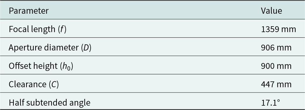
First, a reference parabolic antenna configuration was defined to serve as a benchmark for the analysis of different antenna solutions. This configuration is derived from those commonly employed in geostationary high-throughput satellites in Ka-band for the generation of multi-spot coverages [Reference Veljovic and Skrivervik15], scaled down by a factor of 0.5. The offset height has been defined to enable the use of this reflector architecture in a dual antenna configuration by adding a sub-reflector. Otherwise, a typical offset height would be approximately 600 mm.
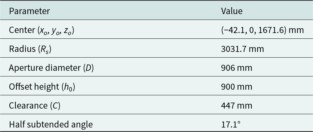
The spherical surface is obtained by Geometrical Optics (GO), sampling the parabolic surface of the reference reflector (given by the parameters shown in Table 1), and taking the normal directions to the parabolic surface, as shown in Figure 1. The center of the sphere can be located as the point of best convergence for the normal rays taken from the paraboloid. When considering the classic Cartesian coordinate system for reflector configurations shown in Figure 1, with the origin at the focal point of the parabola, the sphere center for the reference antenna configuration is placed at (−42.1, 0, 1671.6) mm, as depicted in Figure 1 by a red circle. Then, the radius of the sphere is computed as the root mean square of the distances between the sphere center and each sample at the paraboloid surface, resulting in a radius of 3031.7 mm for the proposed antenna configuration. Therefore, the new spherical reflector configuration could be unequivocally defined by the previous parameters shown in Table 1, replacing the focal length with the sphere radius.
XZ-plane of the parabolic and spheric reflecting configurations with a detailed view of the convergence point for the normal ray tracing.

Geometry of the reference parabolic antenna configuration

The spherical surface has been analyzed by considering incident rays traveling in the −z direction and impinging upon it, which is illustrated in Figure 2. The inherent spherical aberration prevents a perfect convergence of the reflected rays at the original paraboloid focus, as shown in the lower inset of Figure 2. A secondary focus, corresponding to the point of best convergence of the received rays (labelled as “virtual focus” in Figure 2), can therefore be determined. Note that the paraboloid focus and the virtual focus are located very close to each other, resulting in negligible differences for the subsequent design of the spherical reflectarray, regardless of whether the virtual or paraboloid focus is adopted. The phase correction to be implemented by the reflectarray elements can be incorporated into the convergence analysis of the spherical surface, leading to the results shown in the upper inset of Figure 2. As can be observed, this phase adjustment fully compensates for the spherical aberration of the surface for the selected focus.
Convergence analysis of the spherical reflector for the case without phase corrections on the surface (left) and with phase corrections (right) when incident parallel rays in the −z direction are considered, including an enlarged view of the focal point.

The analytical procedure that has been applied to compute the required phase adjustment on the spherical reflectarray considers a vectorial formulation, which is more suitable for dealing with curved surfaces than the conventional approaches [Reference Huang and Encinar12]. First, the concept of virtual normal is introduced, which is defined as the difference between the unit vectors of the reflected ( $\hat r$) and the incident ( $\hat i$) rays at the reflectarray surface:
 \begin{equation}\vec N = \hat r - \hat i\end{equation}
 Figure 3 illustrates a generic point (P) of the curved reflectarray surface, where the local coordinate system is defined by the orthonormal vectors { $\hat \alpha $, $\hat \beta ,$ $\hat n$}. The absolute coordinate system of the antenna is given by the { $\hat x$, $\hat y$, $\hat z$} unit vectors. Figure 3 also depicts the vectors of the incident ray ( $\hat i$, coming from the focal point) and the reflected ray ( $\hat r$, associated with the direction of the beam radiated by the antenna), as well as the obtained virtual normal ( $\hat N$). Note that $\hat N$ is called the virtual normal because it fulfils the Snell’s law of reflection for the $\hat i$ and $\hat r$ vectors (i.e., equal angles of the incident and reflected rays with respect to $\hat N$), although it is not actually normal to the reflectarray surface.
Absolute and local coordinate systems of the reflectarray surface, including the incident and reflecting rays and the virtual normal at a generic point.

When working with curved reflectarrays, the orientation of the local coordinate system { $\hat \alpha $, $\hat \beta ,$ $\hat n$} changes across the surface. For that reason, the absolute reference system { $\hat x$, $\hat y$, $\hat z$} will be used in the upcoming formulation to obtain the required phase adjustment across the reflectarray surface. First, let z(x, y) be the function that describes the curved reflectarray surface in the absolute reference system, which is known a priori. At each point of the surface, the reflectarray elements will introduce a phase adjustment denoted as $\phi \left( {x,\,y} \right)$. This phase shift can be expressed in terms of its equivalent path-length shift, $L\left( {x,\,y} \right)$, which is proportional to the phase shift $\phi \left( {x,\,y} \right)$ at any point of the reflectarray:
 \begin{equation}\Phi \left( {x,\,y} \right) = - \frac{{2\pi }}{\lambda }L\left( {x,\,y} \right)\end{equation}
Therefore, it is more efficient to define the path-length shift in the aperture, i.e., L(x, y), where XY denotes the aperture plane. After some algebraic operations, it can be demonstrated that the virtual normal is related to the partial derivatives of the phase adjustment across the surface, fulfilling the following expression:
 \begin{align}\vec N &= \left( {\begin{array}{*{20}{c}}
{{N_x}} \\
{{N_y}} \\
{{N_z}}
\end{array}} \right) \nonumber \\
&= \frac{1}{{\sqrt {z_x^2 + z_y^2 + 1} }}\left( {\begin{array}{*{20}{c}}
{z_y^2 + 1}&{ - {z_x}{z_y}} \\
{ - {z_x}{z_y}}&{z_x^2 + 1} \\
{{z_x}}&{{z_y}}
\end{array}} \right)\left( {\begin{array}{*{20}{c}}
{{\text{${\partial L}$} \!\mathord{\left/
{\vphantom {{\partial L} {\partial x}}}\right.}
\!\text{${\partial x}$}}} \\
{{\text{${\partial L}$} \!\mathord{\left/
{\vphantom {{\partial L} {\partial y}}}\right.}
\!\text{${\partial y}$}}}
\end{array}} \right)\end{align}
\begin{align}\vec N &= \left( {\begin{array}{*{20}{c}}
{{N_x}} \\
{{N_y}} \\
{{N_z}}
\end{array}} \right) \nonumber \\
&= \frac{1}{{\sqrt {z_x^2 + z_y^2 + 1} }}\left( {\begin{array}{*{20}{c}}
{z_y^2 + 1}&{ - {z_x}{z_y}} \\
{ - {z_x}{z_y}}&{z_x^2 + 1} \\
{{z_x}}&{{z_y}}
\end{array}} \right)\left( {\begin{array}{*{20}{c}}
{{\text{${\partial L}$} \!\mathord{\left/
{\vphantom {{\partial L} {\partial x}}}\right.}
\!\text{${\partial x}$}}} \\
{{\text{${\partial L}$} \!\mathord{\left/
{\vphantom {{\partial L} {\partial y}}}\right.}
\!\text{${\partial y}$}}}
\end{array}} \right)\end{align}The inverse relation reduces to:
 \begin{equation}\left[ {\begin{array}{*{20}{c}}
{{\text{${\partial L}$} \!\mathord{\left/
{\vphantom {{\partial L} {\partial x}}}\right.}
\!\text{${\partial x}$}}} \\
{{\text{${\partial L}$} \!\mathord{\left/
{\vphantom {{\partial L} {\partial y}}}\right.}
\!\text{${\partial y}$}}}
\end{array}} \right] = \left[ {\begin{array}{*{20}{c}}
1&0&{{z_x}} \\
0&1&{{z_y}}
\end{array}} \right]\left[ {\begin{array}{*{20}{c}}
{{N_x}} \\
{{N_y}} \\
{{N_z}}
\end{array}} \right]\end{equation}
\begin{equation}\left[ {\begin{array}{*{20}{c}}
{{\text{${\partial L}$} \!\mathord{\left/
{\vphantom {{\partial L} {\partial x}}}\right.}
\!\text{${\partial x}$}}} \\
{{\text{${\partial L}$} \!\mathord{\left/
{\vphantom {{\partial L} {\partial y}}}\right.}
\!\text{${\partial y}$}}}
\end{array}} \right] = \left[ {\begin{array}{*{20}{c}}
1&0&{{z_x}} \\
0&1&{{z_y}}
\end{array}} \right]\left[ {\begin{array}{*{20}{c}}
{{N_x}} \\
{{N_y}} \\
{{N_z}}
\end{array}} \right]\end{equation} To obtain the phase adjustment required at the spherical reflectarray Φ(x, y), a ray tracing process is applied. For this process, the trajectories of the incident and reflected rays on the reflectarray are known, since all the incident rays must come from the focus, while the reflected rays will be parallel and pointing in the same direction (to generate a plane wavefront). Hence, the virtual normals for a discrete set of reflectarray points can be obtained by (1). Then, the partial derivatives of L(x, y) are computed using (4). A least squares interpolation algorithm is applied to obtain a continuous function for the partial derivatives of L(x, y), which can be expressed in terms of polynomial basis functions  ${\psi _n}\left( {x,\,y} \right)$:
 \begin{equation}\frac{{\partial L\left( {x,\,y} \right)}}{{\partial x}} = \mathop \sum \limits_n {a_n}{\psi _n}\left( {x,\,y} \right)\end{equation}
 where  ${a_n}$ are coefficients that are determined using the least squares condition. The final step of the phase synthesis process consists of obtaining L(x, y) through the integration of its partial derivatives. Once L(x, y) has been completely characterized, the phase adjustment that must be introduced by each reflectarray element on the spherical surface can be easily derived by (2).
For the analysis of the spherical reflectarray, ideal phase-shifters have been considered as the reflectarray elements (i.e., providing the required phase shifts without errors and null reflection losses). The feed has been modeled by a standard cosq(θ) distribution with q = 35 that provides a taper illumination of −14 dB. The analysis frequency is 29.5 GHz, which is a typical uplink frequency for communications satellites operating in Ka-band [Reference Veljovic and Skrivervik15]. The radiation patterns of the spherical reflector have been obtained through Physical Optics (PO) simulation, considering illumination from the paraboloid focus. The results are presented in Figure 4 for the case without phase corrections (“Non-corr.”), i.e., a spherical metallic reflector, and for the spherical reflectarray including the phase corrections of its reflecting elements (“Corr.”). The non-corrected reflector provides a peak gain of 45.4 dBi, a 3-dB beamwidth of 1°, and a slight 0.3° tilt in elevation, whereas the corrected reflector achieves a 1.5 dB gain improvement, a 3-dB beamwidth of 1.13°, and complete suppression of beam deviation. Therefore, after correcting the spherical aberration, the antenna efficiency has been increased from 44% to 62.4%, reaching the radiation efficiency of the equivalent parabolic reflector with −14 dB of taper illumination.
Simulated radiation patterns of the spherical reflector with and without phase corrections: cuts in Elevation (left) and Azimuth (right) planes.

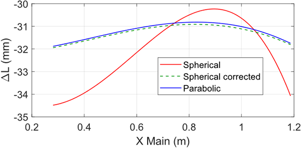
Combined GO/PO techniques have been applied to evaluate the scanning performance of the antenna. The error (in mm) along the offset plane, associated with a 2.5° scanning in the offset plane, is presented in Figure 5, considering three different configurations of the reflector surface: parabolic, spherical, and corrected-spherical. As can be observed, the phase-corrected spherical reflectarray provides the same performance as the parabolic reflector, which demonstrates that spherical reflectarrays are able to compensate for spherical aberration and achieve parabolic-like performance by means of the phase adjustment introduced by their reflecting elements.
Error in mm for different types of reflector surfaces, considering a 2.5° exploration in the offset plane.

Design of large-aperture reflectarrays
Reflectarray antennas have gained significant attention for satellite antenna solutions thanks to their versatility in generating contoured beams [Reference Robustillo, Zapata, Encinar and Arrebola13], enabling polarization conversion directly at the reflecting surface [Reference Martinez-de-Rioja, Imaz-Lueje, Martinez-de-Rioja, Pino, Encinar and Arrebola17], and supporting independent operation in orthogonal polarizations and multiple frequency bands [Reference Martinez-de-Rioja, Martinez-de-Rioja, Encinar, Florencio and Toso21]. These features can lead to a reduction by half in the number of reflectors and feed chains required onboard the satellite to generate a multispot coverage [Reference Martinez-de-Rioja, Martinez-de-Rioja, JA, Pino, Gonzalez-Valdes, Rodriguez-Vaqueiro and Toso22]. Nevertheless, the flat reflecting surface typically employed in large-aperture reflectarrays imposes bandwidth limitations as a result of the differential phase delay effect.
The differential phase delay is associated with the different path lengths of the rays that impinge on the reflectarray and are reflected to form a plane wavefront [Reference Huang and Encinar12]. When the reflectarray consists of a single planar surface, the difference with respect to the paraboloid (ideal case with equal path lengths for all the rays coming from the focus) is maximized, which results in a large range of phase delay values to be compensated by the reflectarray elements. If the phase delays are normalized to a 360° phase range, the required phase distribution on the reflectarray presents a large number of 360° cycles. The reflectarray elements are then designed to provide the required phase shifts, but the design is performed at a single frequency (normally, the central operating frequency). When the frequency changes, the phase delays associated with the different path lengths of the rays also change, so the phase shifts required in the reflectarray elements are slightly different from those previously designed, which produces a certain degradation of the antenna performance. This problem is aggravated in the case of large-aperture flat reflectarrays, where the difference of phase delays across the reflectarray surface is maximized. To mitigate this problem and achieve broadband operation in large-aperture reflectarrays, it is preferable to employ a curved surface (e.g., spherical or parabolic) [Reference Zhou, Sorensen, Brand and Toso20, Reference Martinez-de-Rioja, Martinez-de-Rioja, Rodriguez-Vaqueiro, Pino, Mosquera, JA and Toso23], or, at least, a multifaceted configuration with flat panels that are arranged following a curved profile [Reference Imaz-Lueje, Pino and Arrebola16].
To illustrate the advantages of spherical surfaces in mitigating the problem of differential phase delay, a large-aperture reflectarray with a diameter of 0.9 m has been designed, considering different types of reflecting surfaces to compare the required phase corrections for each surface. The main parameters of the antenna geometry, considering the classical configuration of offset parabolic reflectors, are shown in Table 1. Four different reflectarray designs have been conducted: a conventional single-panel flat reflectarray, a multifaceted reflectarray formed by seven hexagonal panels, a cylindrical reflectarray to increase the mechanical simplicity of the antenna deployment, and a spherical reflectarray. The representation of the different antenna geometries, including the comparison with the reference parabolic surface, is provided in Figure 6.
Antenna geometry for the: (a) flat reflectarray, (b) multifaceted reflectarray, (c) cylindrical reflectarray, and (d) spherical reflectarray configurations. The asterisk represents the focal point, and the shadow region is the reference paraboloid.

The design frequency is 29.5 GHz, which corresponds to the classical uplink frequency in Ka-band satellites. The flat reflectarray is placed in the chordal plane of parabola, the panels of the multifaceted reflectarray are arranged so that they approximate the curved profile of the parabola, the spherical configuration was presented in the previous section, and the cylindrical surface is obtained by applying the same process detailed in the second section to cylindrical surfaces. Note that the cylindrical reflectarray is a curved surface in a single plane (unlike parabolic and spherical surfaces, which are doubly curved surfaces): the cylindrical reflectarray follows a spherical curve in the XZ plane, while it is flat along the Y direction, as can be seen in Figure 6(c).
To compute the required phase correction on the spherical and cylindrical reflectarray surfaces, the vectorial formulation presented in Section II has been applied. On the other hand, for the cases with flat reflectarray panels, a more conventional approach has been considered, based on [Reference Huang and Encinar12]. According to this approach, the phase correction required in each reflectarray cell ( ${\phi _i}$) is directly obtained by (6), which includes the wavenumber at the design frequency ( ${k_0}$), the distance between the feed and the reflectarray cell (di), the pointing angles of the radiated beam (θb, φb) and the cell coordinates (xi, yi):
 \begin{equation}{\phi _i} = {k_0}\left( {{d_i} - \left( {{x_i}\cos {\varphi _b} + {y_i}\sin {\varphi _b}} \right)\sin {\theta _b}} \right)\,\end{equation}
Figure 7 shows the phase corrections (normalized to a 360° phase range) required on the flat, multifaceted, cylindrical, and spherical reflecting surfaces to radiate a collimated beam at broadside. Note that the parabolic reflector does not need any phase correction on its surface, as the parabolic surface produces the beam collimation in a natural way, thus being the reference case for this study (no phase adjustment is required). As shown in Figure 7(a), the flat reflectarray antenna of 0.9-m diameter has a large number of 360° cycles across its surface. This behavior leads to rapid phase variations between neighbor cells, which may have a negative impact when the reflectarray cells are analyzed under the local periodicity approach, as it is typical in many electromagnetic methods for reflectarray antennas [Reference Florencio, Boix and Encinar25]. On the other hand, the multifaceted reflectarray configuration, whose phase distribution is depicted in Figure 7(b), presents a quite smoother phase variation across the surface of each panel (around one 360° cycle). This result confirms the benefits of the multifaceted approach as an efficient strategy to approximate a curved surface using flat reflecting panels. However, increasing the electrical size of the antenna would require a larger number of panels forming the multifaceted reflectarray to better approximate the curved profile and maintain this advantageous performance, which could elevate the mechanical complexity of the antenna deployment. Concerning the phase correction of the cylindrical reflectarray, shown in Figure 7(c), the curvature of the surface allows to reduce the number of phase cycles along its vertical dimension; however, there are still many phase wraps along its horizontal axis. Finally, the phase distribution required on the spherical reflectarray is provided in Figure 7(d). As can be observed, only a small phase adjustment (covering less than 200°) is needed on the surface to correct the spherical aberration with respect to the parabolic case, being the spherical configuration the one with the smallest and smoothest phase variation of three antenna configurations studied in Figure 7. The advantage of such a small phase adjustment is that it could be implemented by simple, single-layer reflectarray cells (e.g., rectangular or circular patches), which normally are not able to provide a full 360° cycle of phase variation.
Phase distributions (°) required to produce a collimated beam at 29.5 GHz for: (a) the flat reflectarray, (b) the multifaceted reflectarray, (c) the cylindrical reflectarray, and (d) the spherical reflectarray. The four configurations present the same aperture diameter (0.9 m).

Thus, the use of spherical surfaces can mitigate the differential phase delay effect with respect to the flat-panel and multifaceted antenna configurations, leading to smooth phase corrections with less than 360° of variation. This characteristic facilitates the design of the reflectarray elements, since there is no need to use complex multi-resonant or multilayer unit cells, as in [Reference Florencio, Encinar, Boix, Losada and Toso18–Reference Martinez-de-Rioja, Martinez-de-Rioja, Encinar, Florencio and Toso21]. Moreover, the dimensions of the reflectarray elements will present a slight variation between neighbor cells, which approximates better the local periodicity condition normally applied to analyze the unit cell. Although the parabolic surface remains the best option in terms of phase correction (because no phase correction is needed), the spherical configuration presents some mechanical advantages, as stated before.
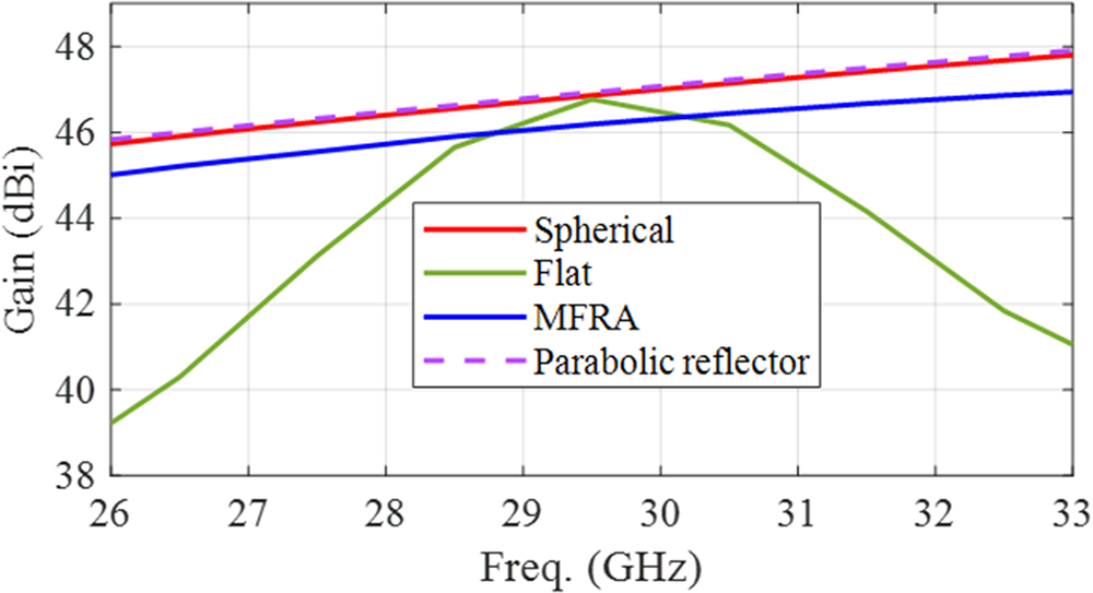
To complete this study, some of the designed antenna configurations (flat reflectarray, multifaceted reflectarray, spherical reflectarray, and the reference parabolic reflector) have been simulated to evaluate their bandwidth performance. The reflectarrays have been analyzed by an in-house simulation tool based on a PO model that takes into account the reflection matrices of the unit cells that form the reflectarray surface, while the reflector has been simulated in GRASP. For this purpose, the maximum gain of the radiation pattern has been analyzed over frequency, considering a frequency range from 26 to 33 GHz. The maximum-gain-versus-frequency curves of the five antenna configurations are provided in Figure 8. The spherical reflectarray exhibits the same in-band performance as a parabolic reflector within the frequencies analyzed. The multifaceted reflectarray shows a slightly worse in-band performance: instead of replicating the behavior of the parabolic reflector, the difference between its curve and the reflector’s curve increases 0.2 dB at 33 GHz. Also, the multifaceted reflectarray shows about 1 dB of additional losses due to the gaps considered between panels, which reduces the incident power captured by the multifaceted reflectarray compared to the single-facet solutions (note that these gaps are caused by the rectangular lattice of unit-cells failing to cover the edge of each hexagonal panel accurately, the gaps could be minimized by a careful definition of the cell dimensions and arrangement). As expected, the worst bandwidth performance occurs for the flat reflectarray due to the differential spatial phase delay.
Simulated maximum gain over frequency for the flat reflectarray, the multifaceted reflectarray, the spherical reflectarray, and the reference parabolic reflector.

Therefore, spherical reflectarrays can be employed for applications similar to those of parabolic reflectors, integrating established design techniques to enable advanced antenna functionalities (such as dual-band operation, multibeam generation, or polarization control), while requiring a minor phase correction to enhance the focusing performance of the spherical surface. From a mechanical standpoint, the rotational symmetry of the spherical geometry facilitates simpler deployment mechanisms compared to those used for offset parabolic reflector antennas.
Spherical reflectarrays in dual antenna configurations
The mechanical benefits of employing a spherical reflector can be further exploited when integrated into dual-reflector configurations, as the one shown in Figure 9, leading to more compact antenna systems. The main reflector of the dual antenna shown in Figure 9 is the same spherical configuration defined in Table 2, previously characterized in a single configuration. Figure 9 shows the convergence analysis performed prior to the correction of the spherical aberration, which reveals only minor discrepancies between the paraboloidal and virtual focal points, similar to the behavior observed before in the single-offset configuration.
Dual antenna configuration with a spherical main reflector and its convergence analysis.

Geometry of the best spherical approach

When designing a dual-antenna system with a main spherical reflector, an additional phase compensation must be incorporated to mitigate the spherical aberration inherent to the main surface, as it happened in the case of the single-offset reflector. The phase compensation can be implemented either on the spherical reflector itself, as outlined in the previous section, or alternatively on the flat sub-reflector. While both approaches achieve comparable phase corrections, GO-based analysis reveals that implementing the correction at the flat sub-reflector results in a smaller sub-reflector size, as illustrated in Figure 10. Hence, the design of the flat sub-reflectarray must explicitly account for the phase compensation of the spherical aberration. Furthermore, the sub-reflectarray could be optimized to correct persistent errors, previously characterized, related to the spherical reflector deployment.
Convergence analysis of the dual antenna when the required phase adjustment is introduced on the sub-reflector (left) or on the main reflector (right).

The dual-reflector system of Figure 10, with the phase correction implemented in the sub-reflector, has been designed to operate at both downlink and uplink frequencies in Ka-band (19.7 and 29.5 GHz). The sub-reflectarray incorporates the phase compensation required to correct the spherical aberration, plus a gradual phase distribution in each polarization to produce a ±0.6° deviation of the orthogonally polarized beams radiated by the feed at both operating frequencies. The resultant phase distributions implemented in the sub-reflectarray, for each polarization and frequency, are depicted in Figure 11. On the other hand, the spherical main reflector is assumed to be a conventional metallic surface. The dual antenna has been simulated considering ideal phase-shifters as reflectarray cells, applying the same analysis technique for dual-reflectarray systems reported in [Reference Martinez-de-Rioja, Martinez-de-Rioja, Rodriguez-Vaqueiro, Pino, Mosquera, JA and Toso23]. A more advanced version of the antenna system could include polarizing reflectarray elements on the main reflector surface, enabling polarization conversion from dual linear to dual circular, as in [Reference Martinez-de-Rioja, Martinez-de-Rioja, Rodriguez-Vaqueiro, Pino, Mosquera, JA and Toso23].
Phase distributions (°) required in the sub-reflector of the dual antenna: (a) in Pol. 1 at 19.7 GHz, (b) in Pol. 2 at 19.7 GHz, (c) in Pol. 1 at 29.5 GHz, and (d) in Pol. 2 at 29.5 GHz.

The dual antenna has been simulated at both operating frequencies, 19.7 and 29.5 GHz, and the resultant radiation patterns, obtained in the plane transversal to the offset plane (i.e., the plane where the orthogonally polarized beams are split) have been depicted in Figure 12. As a reference to evaluate the antenna performance, the plots presented in Figure 12 also include the radiation patterns of the dual-reflector configuration where the sub-reflector only implements the phase adjustment required to correct the spherical aberration, but not the gradual phases required to discriminate the incident polarization and deviate ±0.6° the beams in orthogonal polarization (“non-dis.” curves in Figure 12). As can be seen, for the dual antenna with polarization discrimination, the beams generated at 19.7 and 29.5 GHz in the same polarization are deviated in opposite directions (i.e., the beam pointing at 0.6° changes its polarization between uplink and downlink, and the same applies to the beam pointing at −0.6°). This feature is typical in multispot coverages produced by high-throughput GEO satellites in Ka-band [Reference Martinez-de-Rioja, Martinez-de-Rioja, JA, Pino, Gonzalez-Valdes, Rodriguez-Vaqueiro and Toso22, Reference Martinez-de-Rioja, Martinez-de-Rioja, Rodriguez-Vaqueiro, Pino, Mosquera, JA and Toso23].
Simulated radiation patterns of the dual antenna implementing polarization discrimination in the sub-reflector to deviate ±0.6° the beams in orthogonal polarizations: (a) at 19.7 GHz and (b) at 29.5 GHz.

The multibeam characteristic of the designed dual antenna has been evaluated by including a second feed-horn, adjacent to the original one (located at the focus), in the analysis. This allows to generate four adjacent beams, with a separation of 1.2°, which alternate in polarization, at both downlink and uplink frequencies (19.7/29.5 GHz). The radiation patterns of the multibeam antenna are provided in Figure 13. As can be seen, the extreme beams present a slight degradation in the shape of the main lobe and a gain loss of 0.3 dB at 19.7 GHz and 0.8 dB at 29.5 GHz, since they are produced by a feed that is shifted 54 mm with respect to the antenna focus. The minimum peak gain achieved is 43.5 and 46.4 dBi at 19.7 and 29.5 GHz, respectively, which provides a radiation efficiency over 60% at 19.7 GHz and over 55% at 29.5 GHz.
Simulated radiation patterns of the dual antenna when it is illuminated by two adjacent feeds: (a) at 19.7 GHz and (b) at 29.5 GHz.

These results confirm that spherical reflectarrays can be successfully integrated into dual-reflector architectures, preserving the gain and beam-steering capabilities of conventional parabolic-based systems while providing a more compact and mechanically efficient configuration. The ability to compensate spherical aberration through the sub-reflectarray further reduces the implementation complexity of the main spherical reflector for multibeam and dual-band operation.
Conclusion
This work has presented a comprehensive analysis of spherical reflectarray antennas as a competitive alternative to conventional parabolic reflectors for compact satellite platforms. A parabolic configuration was initially established as a reference to derive the optimal spherical surface through GO, and an analytical formulation was presented to compute the required phase adjustment on the curved reflectarray surfaces.
When compared with flat, multifaceted, and cylindrical reflectarray configurations, the spherical approach has demonstrated significantly reduced phase variations across the aperture, which enables the use of simpler unit cells, improves compliance with local periodicity conditions and increases the operation bandwidth by minimizing the differential spatial phase delay. The bandwidth analysis has revealed that spherical reflectarrays closely replicate the performance of their parabolic counterparts and outperform flat and multi-panel architectures in terms of gain stability over frequency. Furthermore, the integration of spherical reflectarrays in dual-antenna configurations has been validated through simulations at 19.7 and 29.5 GHz, demonstrating proper beam focusing, enhanced radiation efficiency, and effective polarization discrimination for multibeam operation. The results highlight the suitability of spherical reflectarrays for very-high-gain and multibeam satellite applications. Spherical reflectarrays offer a favorable balance between electrical performance and mechanical deployability, making them particularly attractive for next-generation compact and lightweight satellite antenna systems based on offset reflectors.
Acknowledgement
This work was supported in part by the Madrid Government (Comunidad de Madrid-Spain) under the Multiannual Agreement 2023–2026 with Universidad Politécnica de Madrid in the Line A, Emerging PhD researchers (project STARS), by Spanish Government through MCIU/AEI/10.13039/501100011033/FEDER, UE within the projects PID2023-146246OB-C31-2 (ANT4IT), PID2024-161515OA-I00 (brAIn-5G), RYC2021-033593-I and in part by the Regional Government of Galicia under project GRC-ED431C-2023/26 and agreement for funding AtlantTIC.
Competing interests
The authors declare none.

Daniel Martinez-de-Rioja received the B.S. and M.S. degrees in telecommunication engineering from the Universidad Politécnica de Madrid (UPM), Spain, in 2016 and 2018, and the Ph.D. degree from UPM in 2021. In 2018, he started his research career at the Applied Electromagnetics Group (GEA) of UPM, where he completed his Ph.D. under the supervision of Prof. José Antonio Encinar. Currently, he is Associate Professor at the Signal, Systems and Radiocommunications Department, UPM. His research is related to the design of reflectarray antennas and quasi-periodic surfaces applied to communication satellites and smart reflecting surfaces.

Yolanda Rodriguez-Vaqueiro received the B.S. degree in telecommunications engineering from the University of Vigo, Vigo, Spain, in 2009, and the Ph.D. degree in electrical engineering from Northeastern University, Boston, MA, USA, in 2015. She is a Ramon y Cajal Postdoctoral Researcher at the University of Vigo. Her current research interests include advanced signal processing techniques applied to radar imaging systems, reflectarray antennas, reconfigurable intelligent surfaces (RIS), and low-level control system design. Dr. Rodriguez-Vaqueiro’s dissertation was recognized with the Research Impact Award by the Electrical and Computer Engineering Department at Northeastern University.

Antonio Pino received the M.S. and Ph.D. degrees in telecommunications engineering from the Universidad Politécnica de Madrid (UPM), Madrid, in 1985 and 1989, respectively. From 1985 to 1989, he was a Research Assistant with the Radiation Group, UPM. He joined the Department of Technologies of Communications, University of Vigo, Vigo, Spain, as an Associate Professor in 1989, and became a Full Professor in 1994. He joined the Center for Electromagnetics Research, Northeastern University, Boston, MA, USA, in 1993, as a Visiting Researcher. From 2006 to 2010, he was the Vice-Rector with the Academic Organization and Faculty, University of Vigo, where he has been the Director of the International Doctoral School, since 2014. He has authored more than 100 technical articles in journals and conferences and has been an Advisor of 14 Ph.D. thesis. His research interests include reflectarray and shaped reflector antennas for communication and radar applications, high-frequency backscattering, computational electromagnetics, and terahertz technology.

Borja Imaz-Lueje received the B.Sc., M.Sc., and Ph.D. degrees in telecommunication engineering from the Universidad de Oviedo (UO), Gijón, Spain, in 2017, 2019, and 2023, respectively. Since 2016, he has been a Research Assistant with the Electrical Engineering Department, UO. From 2018 to 2019, he spent several months in Rohde & Schwarz GmbH & Co KG, Munich, Germany, where he was involved in the deployment of CATR systems and OTA measurements. In 2022, he was in a research mission with Institut d’Electronique et des Technologies du numeRique, Rennes, France, where he was involved in the analysis and design of compact antennas. In 2023, he joined the Department of Signal Theory and Communications and Telematic Systems and Computing, Universidad Rey Juan Carlos (URJC), Madrid, Spain, where he is currently Assistant Professor. His current research interests include the development of efficient analysis and design techniques of reflectarrays in complex configurations, working in environments of near and far fields.

Eduardo Martinez-de-Rioja received the Telecommunication Engineer and Ph.D. degrees from the Universidad Politécnica de Madrid (UPM), Madrid, in 2014 and 2018, respectively. From 2015 to 2019, he was with the Applied Electromagnetics Group at UPM, as a Research Assistant. In 2016, he joined the Electrical and Computer Engineering Department, University of Toronto, Toronto, Canada, as a Visiting Ph.D. Student. In 2019, he joined the Department of Signal Theory and Communications and Telematic Systems and Computing, Universidad Rey Juan Carlos, Madrid, Spain, where he is currently an Associate Professor with the Microwave Engineering and Radiocommunications Systems Group. He has authored or coauthored more than 80 peer-reviewed journals and conference papers. His research interests include the design of advanced antenna systems based on reflectarrays, frequency selective surfaces, and other planar quasi-periodic structures, for satellite communications and millimeter-wave 5G/6G applications.

Jose A. Encinar received the Electrical Engineering and Ph.D. degrees from the Universidad Politécnica de Madrid (UPM), Madrid, in 1979 and 1985, respectively. Since 1980, he has been with the Applied Electromagnetism and Microwaves Group, UPM. Since 1987, he has been a Post-Doctoral Fellow of the NATO Science Program with Polytechnic University, New York City, NY, USA. Since 1991, he has been a Professor with the Electromagnetism and Circuit Theory Department, UPM. He has authored more than 100 and 50 journal and conference articles and holds five patents on array and reflectarray antennas. His current research interests include numerical techniques for the analysis of multilayered periodic structures, the design of frequency-selective surfaces, printed arrays, and reflectarrays. Dr. Encinar is a member of the Technical Program Committee of several international conferences (European Conference on Antennas and Propagation, ESA Antenna Workshops, and Loughborough Antennas and Propagation Conference).

Manuel Arrebola received the M.Sc. degree in telecommunication engineering from the University of Malaga, Málaga, Spain, in 2002, and the Ph.D. degree from the Technical University of Madrid (UPM), Madrid, Spain, in 2008. From 2003 to 2007, he was a Research Assistant with the Department of Electromagnetism and Circuit Theory, UPM. From 2007 to 2024, he was with the Department of Electrical Engineering, University of Oviedo, Gijón, Spain, where he became an Associate Professor. In 2024, he joined the Department of Signals, Systems and Radiocommunications, UPM, as an Associate Professor with the Applied Electromagnetics Group. He has authored and co-authored more than 250 peer-reviewed journals and conference papers. His current research interests include the application of innovative manufacturing techniques in mm and sub-mm-wave antenna design and the development of efficient analysis, design, and optimization techniques of spatial fed arrays, including reflectarrays and transmitarrays, and periodic structures for near- and far-field applications.

Giovanni Toso received the Laurea (cum laude) and Ph.D. degrees and the Post-Doctoral Fellowship from the University of Florence, Florence, Italy, in 1992, 1995, and 1999, respectively. In 1996, he joined the Laboratoire d’Optique Electromagnétique, Marseille, France, as a Visiting Scientist. In 1999, he joined the University of California at Los Angeles (UCLA), Los Angeles, CA, USA, as a Visiting Scientist. He has been appointed as Researcher of a Radio Astronomy Observatory with the Italian National Council of Researches (CNR), Rome, Italy. Since 2000, he has been with the Antenna and Sub-Millimeter Waves Section, European Space Agency, ESA ESTEC, Noordwijk, The Netherlands. He has been initiating and contributing to several research and development activities on satellite antennas based on arrays, reflectarrays, lenses, and reflectors. He has coauthored the best article at the 30th ESA Antenna Workshop and the most innovative article at the 30th and 36th ESA Antenna Workshops. Dr. Toso received, with Prof. A. Skrivervik, the Best Teacher Award of the European School of Antennas (ESoA) out of 101 teachers, in 2018.


 Open access