


1 Introduction
Femtosecond fiber lasers are in high demand due to their good beam quality, high stability, low cost and compactness. They have been utilized to generate high-harmonics and terahertz radiation[ Reference Klas, Kirsche, Gebhardt, Buldt, Stark, Hädrich, Rothhardt and Limpert1, Reference Buldt, Stark, Muller, Grebing, Jauregui and Limpert2]. However, the long propagation length and the limited core diameter intensify the nonlinear effects and distort the pulse quality, hindering the scaling of the system performance. To alleviate nonlinearity, chirped pulse amplification (CPA) is widely adopted to improve the output energy. At present, the femtosecond fiber laser system can output 2.2-mJ pulse energy, but output energy is limited by the damage threshold[ Reference Eidam, Rothhardt, Stutzki, Jansen, Hadrich, Carstens, Jauregui, Limpert and Tunnermann3]. Furthermore, the thermal problem cannot be neglected when fiber lasers work in high-power operation. The onset of transverse mode instability distorts the beam quality and limits the scaling of average power[ Reference Jauregui, Limpert and Tuennermann4]. In the past decade, coherent beam combination has demonstrated its unique ability to solve these problems, multiplying the output power and energy[ Reference Muller, Aleshire, Klenke, Haddad, Legare, Tunnermann and Limpert5, Reference Stark, Benner, Buldt, Klenke and Limpert6]. In addition to pulse energy and average power, pulse duration is also demanded for some applications. Although the Yb-doped fiber has a broad gain spectrum, the output pulse duration of high-energy fiber amplifiers is almost more than 200 fs due to the gain narrowing effect[ Reference Pedersen, Johansen, Olesen, Michieletto, Gaponenko and Maack7, Reference Manchee, Möller and Miller8]. To generate shorter pulse duration, some methods have been proposed to broaden the output spectrum.
The simplest method is spectral shaping, which pre-attenuates spectral components around gain peak. It usually places spectral notch filters before the amplifier to shape the spectrum and has been demonstrated to deliver 55-fs pulses in a fiber CPA system with low pulse energy[ Reference Takada, Chiba, Yoshitomi, Torizuka and Misawa9]. However, notch filters have fixed parameters and only supply a weak attenuation, which is not suitable for high-gain fiber CPA systems. A spatial light modulator is a powerful tool to flexibly tailor the spectrum and can supply strong attenuation; it has been used to achieve 130-fs, 250-μJ pulses in a rod-type fiber amplifier and 120-fs, 10-mJ pulses in a coherently combined fiber CPA system[ Reference Lavenu, Natile, Guichard, Zaouter, Hanna, Mottay and Georges10, Reference Stark, Buldt, Muller, Klenke and Limpert11]. However, the shortest pulse duration is around 100 fs in the high-energy CPA system, and shorter pulse duration is difficult to achieve under high gain.
Nonlinear pulse compression techniques, which rely on spectral broadening induced by the Kerr effect and subsequent chirp compensation, have been developed to generate few-cycle pulses[ Reference Nagy, Hädrich, Simon, Blumenstein, Walther, Klas, Buldt, Stark, Breitkopf, Jójárt, Seres, Várallyay, Eidam and Limpert12– Reference Okamoto, Kunihashi, Shinohara, Sanada, Oguri and Chen14]. However, such systems require a long optical arrangement, and the nonlinear effect induces the modulated spectrum, resulting in pulse pedestals[ Reference Escoto, Viotti, Alisauskas, Tünnermann, Hartl and Heyl15].
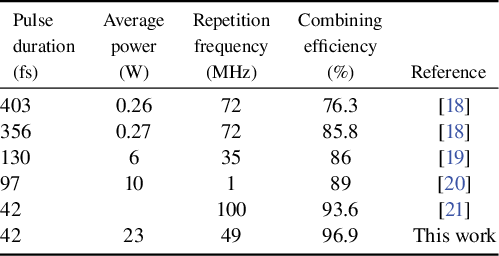
In recent years, coherently combining several channels with different spectral regions has been demonstrated to generate shorter pulses. Spectral coherent combining (SCC) was first widely used to achieve few-cycle or even sub-cycle pulses, and was then extended to Yb-doped fiber amplification systems to overcome the gain narrowing effect[ Reference Manzoni, Mücke, Cirmi, Fang, Moses, Huang, Hong, Cerullo and Kärtner16, Reference Ge, Liu, Chen, Tian, Song, Chai and Hu17]. Combining several fiber amplifiers with different spectra was firstly demonstrated in 2013, and was used to generate a broadened spectrum compared with a single amplifier under the same high gain[ Reference Chang, Zhou, Siiman and Galvanauskas18, Reference Guichard, Hanna, Lombard, Zaouter, Honninger, Morin, Druon, Mottay and Georges19]. Then, 97-fs pulse duration and 10-μJ pulse energy were achieved from a two-channel fiber amplification system based on SCC with high-order dispersion compensation[ Reference Guichard, Hanna, Chiche, Zaouter, Zomer, Morin, Hönninger, Mottay and Georges20]. Moreover, combining spectral shaping and high-order dispersion compensation, a three-channel fiber amplification system based on SCC can generate 42-fs pulses, but the average power is low and the pulse shows obvious pedestals[ Reference Chen, Zhou, Du, Wang, Gilardi, Vay, Li, van Tilborg, Schroeder, Esarey, Wilcox and Geddes21]. Table 1 summarizes the experimental results of Yb-doped fiber amplification systems based on SCC. Normally, the combining efficiency is less than 90% for most fiber amplification systems based on SCC and the combining efficiency can be improved by decreasing the overlapping spectral range, but this greatly degrades the pulse quality. Therefore, it is necessary to analyze the combining process and study how to improve the combining performance to achieve high combining efficiency and high pulse quality.
Overview of Yb-doped fiber amplification systems based on SCC.

In this paper, we investigate the SCC of two beams to achieve high combining performance. Firstly, we analyze the combining process and find that incident spectra and the transition region of the combiner both affect the combining performance. Then, the numerical simulation indicates that more overlapping spectra can improve the combined pulse quality while sacrificing the combined pulse duration. On the other hand, the combining performance can be improved by optimizing the start wavelength (SW) and transition width (TW) of the combiner. Moreover, a few overlapping spectra relax the strict requirement for the TW and SW of the combiner and can easily achieve a high combining efficiency. Besides, the spectral phase mismatch also affects the combining process, but SCC is less sensitive to the spectral phase difference than filled-aperture combining. According to these simulation results, we built a femtosecond laser system based on the SCC of two fiber amplifiers, achieving 96.9% combining efficiency and generating high-quality 42-fs pulses. To the best of our knowledge, this is the first time that high combining efficiency and high pulse quality have been achieved simultaneously in a fiber femtosecond laser system based on SCC. This work provides design guidelines for the high-performance combination of beams covering different spectral regions.
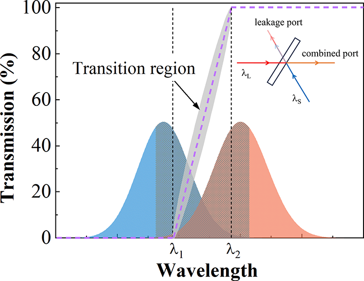
The typical transmittance curve of the LP-DM (purple dashed line), spectra of incident beams (shaded area) and their overlapping part (grid area). Here, λ1 and λ2–λ1 are referred to as the SW and TW, respectively. The inset shows the combining process.
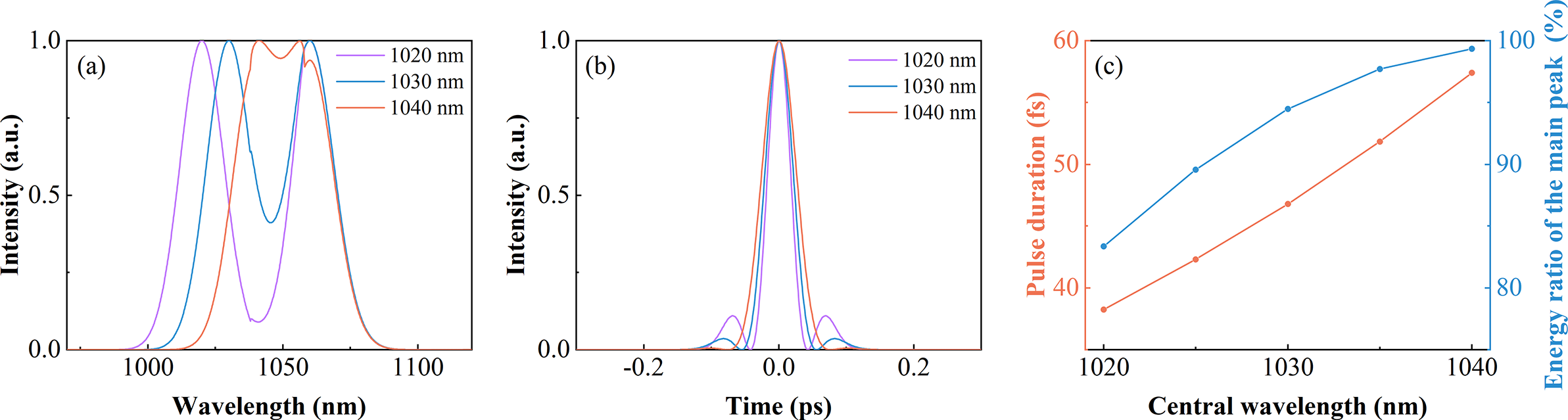
The combined spectra (a) and pulses (b) under different CW-SWCs. (c) The energy ratio of the main peak and pulse duration of the combined pulse versus the CW-SWC.
2 Numerical simulation
In SCC, a dichroic mirror (DM) is always used as the combiner and plays an important role in the combining process. The combining efficiency, as well as the spectrum and pulse quality of the combined beam, is related to the transmittance curve of the DM. Taking the long-pass dichroic mirror (LP-DM) as an example, as shown in Figure 1, a polyline represents the typical transmittance curve of the LP-DM (purple dashed line) and a transition region exists on the transmittance curve of the LP-DM (gray shaded area), which cannot be very sharp due to the limitation of coating technology. Here, λ1 and λ2 represent edge wavelengths of the transition region; λ1 and λ2–λ1 are referred to as the SW and TW, respectively. In the combining process, the spectra of the transmitted and reflected beams are on both sides of the transmittance curve, with some overlapping spectra in the transition region (Figure 1). It is obvious that the transition region greatly affects the combining performance, but it has not been analyzed in detail. In this section, we concentrate on the combining process, and numerically investigate the influences of incident spectra and the transition region of the combiner on this process.
For SCC, when the LP-DM is used as a combiner, two beams with long-wavelength λL and short-wavelength λS combine into a beam with a wide spectrum (Figure 1 inset); the in-phase combining efficiency for each spectral component is as follows:
 $$\begin{align}\eta \left(\lambda \right)=\frac{P_\mathrm{com}\left(\lambda \right)}{P_\mathrm{S}\left(\lambda \right)+{P}_\mathrm{L}\left(\lambda \right)}=\frac{{\left(\sqrt{P_\mathrm{L}\left(\lambda \right)\cdot T\left(\lambda \right)}+\sqrt{P_\mathrm{S}\left(\lambda \right)\cdot \left(1-T\left(\lambda \right)\right)}\right)}^2}{P_\mathrm{S}\left(\lambda \right)+{P}_\mathrm{L}\left(\lambda \right)},\end{align}$$
where P S and P L are the spectral power of the two beams and T is the transmittance of the combiner. Only when the incident power ratio is equal to the splitting ratio (P S(λ) / P L(λ) = (1–T(λ)) / T(λ)) can it achieve a perfect combination[ Reference Siiman, Chang, Zhou and Galvanauskas22]. In other words, by matching the spectral intensity of each channel to the splitting ratio of the combiner at each wavelength, it is possible to achieve the highest combining efficiency. Thus, the spectra of incident beams and the transition region of the combiner both affect the combining process. In the following, we numerically simulate SCC of two beams with identical energy under the in-phase condition to investigate the influences of incident spectra and the transition region of the combiner on the combining process.
2.1 Influence of incident spectra
Firstly, the influence of the interval between the central wavelengths of beams on combined pulses is investigated. The two pulses are 80-fs transform-limited (TL) Gaussian pulses. The central wavelength of the long-wavelength channel (CW-LWC) is 1060 nm, and the central wavelength of the short-wavelength channel (CW-SWC) gradually red-shifts from 1020 to 1040 nm. They are combined by a DM with 20-nm TW and 1038-nm SW, and the results are shown in Figure 2. As the CW-SWC blue-shifts, the overlapping spectral range decreases, leading to a broadened spectrum with a deep and wide gap (Figure 2(a)). As a result, the combined pulse shows shorter pulse duration, accompanied by the presence of side lobes (Figure 2(b)). This also reduces the energy ratio of the main peak over the whole pulse[ Reference Staels, Jarque, Carlson, Hemmer, Kapteyn, Murnane and Roman23] (Figure 2(c)). Overall, fewer overlapping spectra can combine a shorter pulse duration while sacrificing the pulse quality for fixed incident pulse durations, so there should be a tradeoff between the pulse duration and pulse quality.
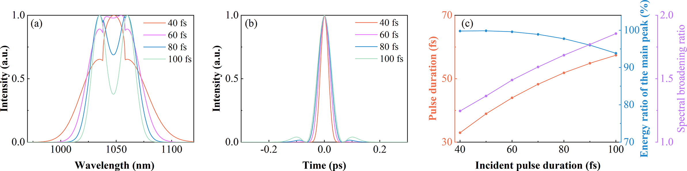
Then, the influence of spectral bandwidths of two beams on combined pulses is investigated. The two pulses are TL Gaussian pulses, centered at 1035 and 1060 nm, respectively, and they are combined by a DM with 20-nm TW and 1038-nm SW. When the spectral bandwidth increases, the corresponding pulse duration decreases. Therefore, we change the incident pulse duration to represent the change of spectral bandwidth. As incident pulses gradually shorten from 100 to 40 fs, the combined spectrum broadens and the gap disappears (Figure 3(a)). As a result, the combined pulse shows shorter pulse duration and higher energy ratio of the main peak (Figure 3(c)). However, the combined pulse does not significantly shorten compared with incident pulses. For example, two 100-fs pulses can combine a 57-fs pulse, but the combination of two 40-fs pulses only can generate a 33-fs pulse. This indicates that the advantage of SCC gradually weakens as incident pulses shorten. To illustrate this phenomenon, the spectral broadening ratio is introduced, which is equal to the combined spectral bandwidth divided by the incident spectral bandwidth. As the incident pulse shortens, the overlapping spectral range gradually increases, which decreases the spectral broadening ratio, so the combined pulse duration becomes slightly shorter (Figure 3(b)). Overall, more overlapping spectra can improve the combined pulse quality while sacrificing the pulse duration.
The combined spectra (a) and pulses (b) under different incident pulse durations. (c) The energy ratio of the main peak, pulse duration and spectral broadening ratio of combined pulses versus the incident pulse duration.

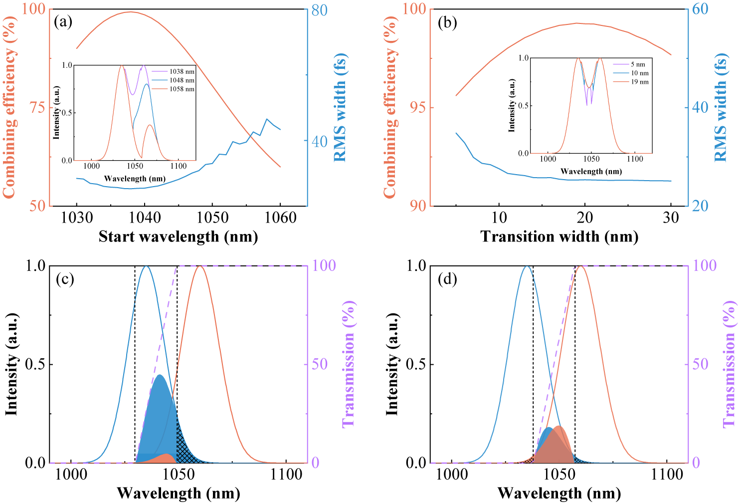
(a) The combining efficiency and RMS width of the combined pulse versus the SW under 19-nm TW. The inset shows combined spectra under different SWs. (b) The combining efficiency and RMS width of the combined pulse versus the TW. The inset shows combined spectra under different TWs. (c) Incident spectra (solid lines), uncombined spectra of the leakage port (shaded area), non-overlapping spectra of the leakage port (grid area) and the transmittance curve of the combiner (purple dashed line) under 19-nm TW and 1030-nm SW. (d) Incident spectra (solid lines), uncombined spectra of the leakage port (shaded area), non-overlapping spectra of the leakage port (grid area) and the transmittance curve of the combiner (purple dashed line) under 19-nm TW and 1038-nm SW.

2.2 Influence of the transition region of the combiner
Next, the influence of the SW of the combiner on the combining process is investigated. The two pulses are 80-fs TL Gaussian pulses, centered at 1035 and 1060 nm, respectively, and combined by a DM with 19-nm TW and different SWs. As shown in Figure 4(a), the SW greatly affects the combining efficiency and there exists an optimal value (1038 nm) to achieve the highest combining efficiency. To illustrate this phenomenon, the transmittance curves of combiners with 1030 and 1038-nm SW, as well as the corresponding uncombined spectra of the leakage port, are shown in Figures 4(c) and 4(d), respectively. When the SW deviates from 1038 nm, the power of the non-overlapping spectra of the leakage port (Figure 4(c) grid area) increases. On the other hand, the spectral powers of the two beams in the overlapping region are significantly different at the leakage port, so they cannot completely achieve destructive interference. This can be attributed to the mismatch between the incident spectra and transmittance curve of the combiner, which results in a decline in the combining efficiency. Besides, the root mean square (RMS) width of the combined pulse increases with the SW deviating from the optimal value (Figure 4(a)), indicating that the pulse quality gradually degrades. As the SW deviates from the optimal value, the power ratio of the long-wavelength components over the combined spectrum decreases, which induces asymmetry and a significant gap in the spectra (Figure 4(a) inset), resulting in decreasing pulse quality.
Then, the influence of the TW is investigated, as shown in Figure 4(b). For every TW, the SW is chosen to achieve the highest combining efficiency. Although there exists an optimal TW to achieve the highest combining efficiency, the combining efficiency is always larger than 98% when the TW changes from 11 to 28 nm. In addition, the pulse quality slightly degrades under the small TW due to the gap of spectra (Figure 4(b) inset). Thus, high combining efficiency can be achieved within a wide range of TWs of the combiner. Overall, the SW and TW should be carefully adjusted to achieve high combining efficiency and high pulse quality, and the SW is more important for the combining process.
For further discussion and comparison, the influences of the TW and SW are investigated under different CW-SWCs. The two pulses are 80-fs TL Gaussian pulses, and the CW-LWC is fixed at 1060 nm. Figures 5(a)–5(d) show the combining efficiency versus the TW and SW when the CW-SWC is 1010, 1020, 1030 and 1040 nm, respectively. It can be seen that the region for the combining efficiency of more than 99% (encircled by the white dashed line) becomes narrower when the CW-SWC red-shifts. As the CW-SWC red-shifts, the overlapping spectral range increases (Figure 5(e)), and the power ratio of overlapping spectra over the whole spectrum also increases. Thus, the mismatch between incident spectra and the transmittance curve of the combiner has a greater influence on the combining efficiency, resulting in the region for the combining efficiency of more than 99% reducing. This also leads to the highest combining efficiency decreasing with the CW-SWC red-shift (Figure 5(f)). Besides, as the CW-SWC red-shifts, the TW needs to be increased to match the increase of the overlapping spectral range in order to achieve the highest combining efficiency, as shown in Figure 5(f).
Combining efficiency versus the TW and SW under the CW-SWC of (a) 1010 nm, (b) 1020 nm, (c) 1030 nm and (d) 1040 nm. (e) The incident spectra under different CW-SWCs. (f) The highest combining efficiency and the optimal TW versus the CW-SWC.
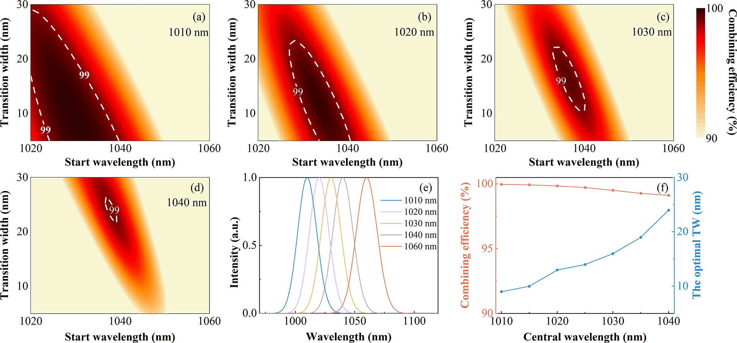
Although the highest combining efficiency can only be achieved by the combiner with a small TW for a few overlapping spectra, the combiner with a large TW can also achieve high combining efficiency. For example, as shown in Figure 5(a), the highest combining efficiency is nearly 100% under the optimal TW (9 nm); the combiner with 20-nm TW can also achieve 99.8% combining efficiency. This can alleviate the need for a high-cost DM with a sharp transition region.
2.3 Influence of the spectral phase mismatch
The above results and analysis only consider the in-phase combination of TL pulses. However, the spectral phase mismatch between beams will affect the combining process and should be investigated. We simulate the combination of two 80-fs TL Gaussian pulses centered at 1035 and 1060 nm, respectively, combined by a DM with 19-nm TW and 1038-nm SW. In addition, one pulse is applied with an extra zeroth-order phase φ0, delay φ1, group delay dispersion φ2 and third-order dispersion φ3, respectively, and results are shown as Figures 6(a)–6(d). The mismatch of the zeroth-order phase slightly affects the combining process. The precise matching for the delay is not necessary, as a delay of less than 20 fs (25% pulse duration) has almost no effect on the combining process. Besides, a 2000-fs2 Δφ2 and 2×10⁵-fs3 Δφ3 only cause a change in the combining efficiency and pulse duration of less than 2% and 4 fs, respectively, indicating that the combination is almost unaffected by the mismatched φ2 and φ3. At the same time, the RMS width slowly increases with Δφ2 and Δφ3, indicating that the pulse quality slowly degrades, but the combined pulse still maintains a high pulse quality.
(a)–(d) The combining efficiency, pulse duration and RMS width of the combined beam by SCC versus the spectral phase mismatch. (e)–(h) The combining efficiency, pulse duration and RMS width of the combined beam by filled-aperture combining versus the spectral phase mismatch.
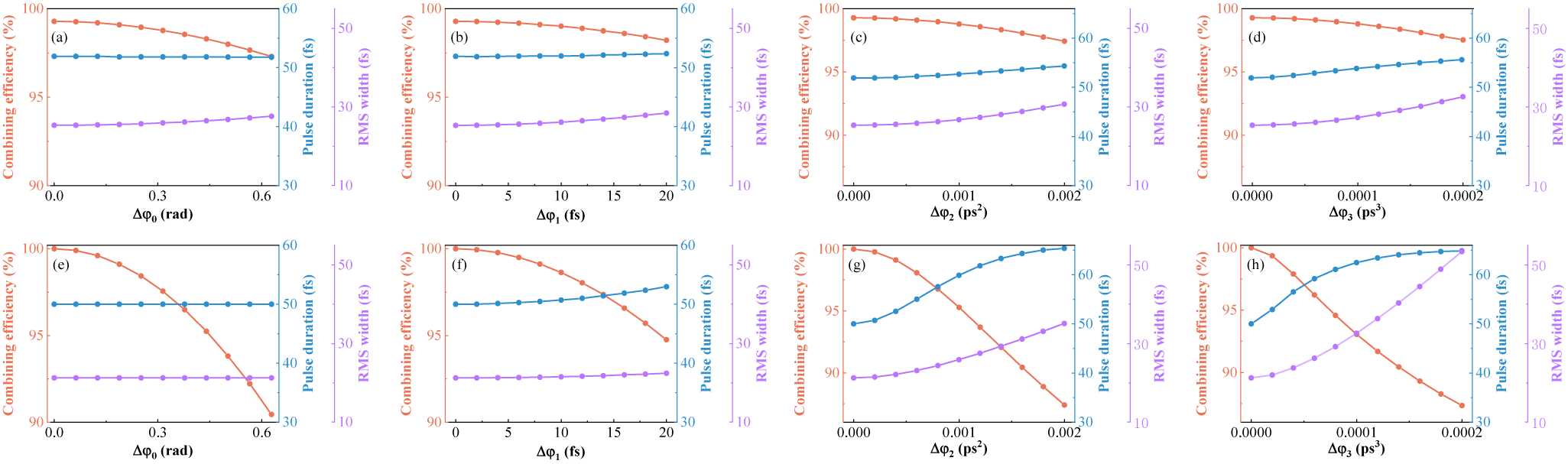
For comparison, the influence of spectral phase mismatch on two-channel filled-aperture combining with identical spectra is investigated. The two pulses are 50-fs TL Gaussian pulses centered at 1040 nm with the same energy and combined by a 50:50 beam splitter (BS); one pulse is applied with the extra spectral phase. The combining efficiency is more sensitive for the mismatched zeroth-order phase and delay compared to the SCC, as shown in Figures 6(e)–6(h). Moreover, the combining efficiency, pulse duration and RMS width are greatly affected by Δφ2 and Δφ3. We can conclude that SCC is not sensitive to the spectral phase mismatch between beams, but the spectral phase mismatch is essential to filled-aperture combining, which makes the control technique more difficult and complex. Thus, SCC is preferred to overcome the influence of the spectral phase mismatch between beams and achieve a nearly perfect combining process.
Now, we have performed the simulation about influences of incident spectra and the transition region of the combiner on the combining process. To achieve high combining efficiency and high pulse quality, some overlapping spectra must exist between beams and optimizing the SW and TW of the combiner is necessary. In addition, spectral phase mismatch should be minimized.
3 Experiment and results
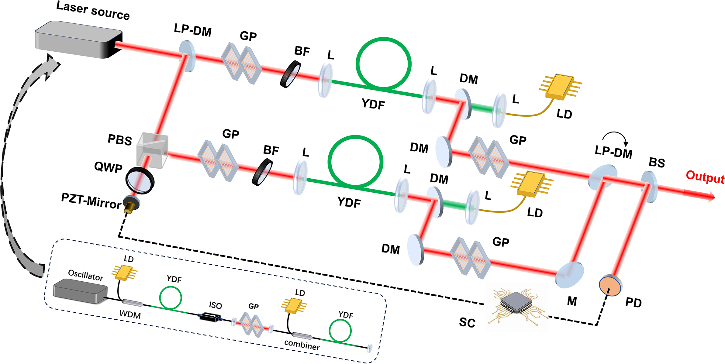
Based on the numerical simulation above, we built a two-channel SCC system. The experimental setup is shown as Figure 7. The laser source is a 49 MHz femtosecond fiber laser with an Yb-doped fiber oscillator and two-stage pre-amplifiers that employ nonlinear amplification technology to generate a broadband spectrum (inset of Figure 7)[ Reference Wang, Liu, Gu, Song, Qian, Hu, Chai and Wang24]. Then, the output beam is split into two channels by an LP-DM and the reflected beam passes a piezo-driven mirror located on a translation stage to compensate the phase noise and match the optical path length. In each channel, a 1000 lines/mm transmission grating pair and a 6-nm bandpass filter are used to adjust the pre-chirp and central wavelength to optimize the pulse evolution in the main amplifier. The main amplifiers are two different Yb-doped tapered double-cladding fibers, counter-pumped by a laser diode (976 nm). Gain fiber 1 has monotonically increasing core and cladding diameters along the 1.8-m fiber with 25 dB/m pump absorption at 976 nm and the core diameters are about 9 and 40 μm, respectively, on the thin and wide sides. Gain fiber 2 only has a 0.7-m taper region at the middle part with 8 dB/m pump absorption at 976 nm and the core diameters are 35 and 56 μm, respectively, on the 1.2-m thin and 0.5-m wide sides. After amplification, the output pulses are compressed by a 1000 lines/mm transmission grating pair. Then, compressed pulses with different spectra are combined by an LP-DM and a small part of the combined beam is directed to the photodiode for active phase stabilization by a 1:99 BS, while the main part is sent into the power meter. The stable constructive superposition is performed by single-detector electronic frequency tagging (LOCSET), a beam is used as the reference and another is imprinted by the 9 kHz tagging frequency[ Reference Shay, Benham, Baker, Sanchez, Pilkington and Lu25]. The system control demodulates the error signal and applies it to the piezo-driven mirror to achieve a closed loop.
Schematic of the experimental setup. WDM, wavelength division multiplexer; ISO, isolator; LP-DM, long-pass dichroic mirror; HWP, half-wave plate; QWP, quarter-wave plate; PBS, polarizing beam splitter; PZT-Mirror, piezo-driven mirror; GP, grating pair; BF, bandpass filter; YDF, Yb-doped fiber; L, lens; DM, dichroic mirror; M, mirror; BS, beam splitter; PD, photodiode; LD, laser diode; SC, system control. The inset shows the schematic of the laser source.

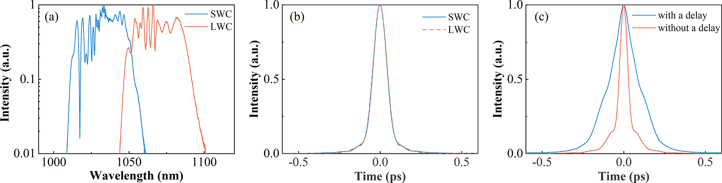
(a) The output spectra and (b) AC traces of two channels. (c) The AC traces of the combined beam with different delays.
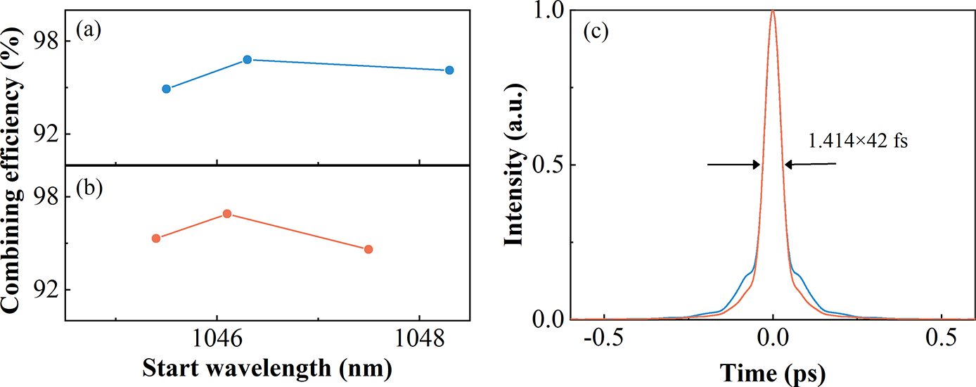
The combining efficiency versus the SW of the combiner with (a) small (12 nm) and (b) large (20 nm) TW. (c) The AC traces of combined pulses with small (blue) and large (red) TW under the highest combining efficiency.
In the experiment, the input energy and initial chirp are adjusted to achieve the nearly TL amplified pulse after compression under the fixed pump power for two channels. The output average powers are 12.4 and 11.4 W, respectively, and the corresponding nonlinear phases are 8π and 6π. The output spectra are shown in Figure 8(a); there is an overlapping spectral region of 1042–1060 nm to ensure phase locking and achieve high pulse quality of the combined beam. The autocorrelation (AC) traces of the dechirped pulses of two channels are shown in Figure 8(b); the pulse durations are 70 and 73 fs, respectively, close to TL duration of 68 fs. In the combination, the combining efficiency and combined pulse duration are both sensitive to the delay. Unfortunately, they cannot achieve optimal results simultaneously by changing the delay. The highest combining efficiency is 97.3%, but it decreases to 96.8% when the delay is tuned to zero to obtain the shortest AC duration, as shown in Figure 8(c). This behavior can be understood as the delay can partially compensate the phase difference, but the induced delay will affect the combined pulse. In fact, the combining efficiency is related to the phase difference of two beams, and the AC duration of the combined beam is related to the temporal overlap of the two pulses. Therefore, the induced delay compensating the spectral phase difference causes the separation of the two pulses, resulting in higher combining efficiency and longer pulse duration. In the experiment, the delay should be adjusted to achieve the shortest pulse duration, because SCC is proposed to generate a short pulse duration.
As mentioned in the numerical simulation, the SW of the combiner can greatly influence the combining efficiency. Thus, we change the SW of the combiner by tuning the incident angle of the beam to the combiner in order to improve the combining efficiency; the results are shown in Figure 9(a). The highest combining efficiency is 96.8% and the corresponding combined pulse duration is 42 fs, but the pulse quality is not high (Figure 9(c) blue line). According to previous results, the appropriate TW may improve the combining performance, so another LP-DM with a large TW (20 nm) is employed to optimize the combination, as shown in Figure 9(b). The highest combining efficiency is 96.9%; the corresponding combined pulse duration is 42 fs and the pulse quality is significantly improved (Figure 9(c) red line). Thus, it is demonstrated that the high combining efficiency and high-quality pulses can be obtained by optimizing the SW and choosing the appropriate TW of the DM.
4 Conclusion
In conclusion, the SCC system employing the DM as a combiner is investigated in detail. The preliminary analysis indicates that incident spectra and the transition region of the combiner both affect the combining process, and the highest combining efficiency can be achieved when the spectral intensity of each channel matches the splitting ratio of the combiner at each wavelength. Then, a numerical simulation is performed to investigate the influences of incident spectra and the transition region of the combiner on the combined pulse and combining efficiency. The simulation results show that more overlapping spectra can improve the combined pulse quality while sacrificing the pulse duration. Moreover, the TW and SW both affect the combining efficiency and combined pulse quality, and they should be optimized to achieve high combining performance. Besides, a few overlapping spectra of beams relax the strict requirement for the TW and SW of the combiner and easily achieve a high combining efficiency. On the other hand, the spectral phase mismatch also affects the combining process, but SCC is less sensitive to the spectral phase difference than filled-aperture combining. Guided by the above results, an experiment is designed to achieve SCC of two fiber amplifiers, and the system generates a 42-fs high-quality pulse with 96.9% combining efficiency by optimizing the parameters of the combiner. This system outperforms previously demonstrated sources due to the high combining efficiency and high pulse quality.
Acknowledgements
This work was supported by the National Natural Science Foundation of China (Grant No. 62435005) and the National Key Research and Development Program of China (Grant No. 2021YFB3602600).


 Open access