


1. Introduction
We consider the collective behaviour of a group of bluff bodies with circular cross-sections (cylinders) placed in the wake of a fixed cylinder. When a bluff body with a circular cross-section is placed in flow, vortices are shed in its wake. These vortices exert fluctuating flow forces on the structure itself and any other structure that is placed in close vicinity of the original bluff body. The interactions between the vortices that are shed from one bluff body and structures placed in its vicinity have been studied extensively in the past. Typical examples of such studies are cases in which flow behaviour around two (or more) cylinders placed in tandem, side-by-side or in a staggered configuration are studied, where all cylinders are fixed and the focus is mainly on the flow behaviour around them. There are also cases where some or all of the cylinders placed in tandem or a side-by-side arrangement are flexibly mounted and therefore can oscillate due to their interactions with the fluctuating forces caused by the vortices that are shed from the bluff body itself or the vortices shed from the neighbouring bluff bodies. In this work, we consider cases where the cylinders that are placed in the wake are free to move in a direction perpendicular to the direction of the incoming flow, without any spring or damper attached to them. These cylinders are only influenced by the flow forces.
When rigid cylinders are placed in tandem, the gap between the cylinders is the main contributor to changes in the flow behaviour around the cylinders (Carmo et al. Reference Carmo, Sherwin, Bearman and Willden2011; Dehkordi, Moghaddam & Jafari Reference Dehkordi, Moghaddam and Jafari2011). Zdravkovich (Reference Zdravkovich1977) detailed a general classification of flow behaviour around tandem cylinders for different values of $L/D$
(where
$L/D$
(where $D$
is the cylinder diameter and
$D$
is the cylinder diameter and $L$
is the centre-to-centre distance between two cylinders) based on experimental studies conducted at Reynolds numbers (Re) ranging from approximately
$L$
is the centre-to-centre distance between two cylinders) based on experimental studies conducted at Reynolds numbers (Re) ranging from approximately $2 \times 10^3$
to
$2 \times 10^3$
to $2 \times 10^5$
. In general, three regimes are observed: an extended-body regime at small
$2 \times 10^5$
. In general, three regimes are observed: an extended-body regime at small $L/D$
, a reattachment regime at intermediate
$L/D$
, a reattachment regime at intermediate $L/D$
and a co-shedding regime at larger values of
$L/D$
and a co-shedding regime at larger values of $L/D$
. Other studies (Igarashi Reference Igarashi1981, Reference Igarashi1984; Alam & Zhou Reference Alam and Zhou2008; Alam et al. Reference Alam, Elhimer, Wang, Jacono and Wong2018) were also conducted at varying
$L/D$
. Other studies (Igarashi Reference Igarashi1981, Reference Igarashi1984; Alam & Zhou Reference Alam and Zhou2008; Alam et al. Reference Alam, Elhimer, Wang, Jacono and Wong2018) were also conducted at varying $L/D$
ratios, varying diameter ratios of the tandem cylinders,
$L/D$
ratios, varying diameter ratios of the tandem cylinders, $d/D$
, and varying Reynolds numbers to show, among other things, that the gap sizes to observe reattachment are Reynolds number dependent. For Re = 200, the gap size to observe reattachment in two tandem cylinders is up to
$d/D$
, and varying Reynolds numbers to show, among other things, that the gap sizes to observe reattachment are Reynolds number dependent. For Re = 200, the gap size to observe reattachment in two tandem cylinders is up to $L/D = 3$
(Meneghini et al. Reference Meneghini, Saltara, Siqueira and Ferrari2001) and, therefore, for a gap size of
$L/D = 3$
(Meneghini et al. Reference Meneghini, Saltara, Siqueira and Ferrari2001) and, therefore, for a gap size of $L/D = 2$
(considered here), no vortex shedding in observed between the upstream and downstream cylinders. In side-by-side arrangements also, the gap size is the main parameter that influences the flow behaviour (Hesam & Navid Reference Hesam and Navid2011). For small
$L/D = 2$
(considered here), no vortex shedding in observed between the upstream and downstream cylinders. In side-by-side arrangements also, the gap size is the main parameter that influences the flow behaviour (Hesam & Navid Reference Hesam and Navid2011). For small $H/D$
(where
$H/D$
(where $H$
is the vertical distance between centres of two adjacent cylinders), a single bluff-body vortex shedding is observed – the two cylinders act as one rigid body. At medium
$H$
is the vertical distance between centres of two adjacent cylinders), a single bluff-body vortex shedding is observed – the two cylinders act as one rigid body. At medium $H/D$
values, biased flow with synchronised vortex shedding is observed and at high
$H/D$
values, biased flow with synchronised vortex shedding is observed and at high $H/D$
, symmetric flow with synchronised vortex shedding (Sumner et al. Reference Sumner, Wong, Price and Paidoussis1999). For smaller gap sizes, i.e.
$H/D$
, symmetric flow with synchronised vortex shedding (Sumner et al. Reference Sumner, Wong, Price and Paidoussis1999). For smaller gap sizes, i.e. $H/D \leqslant 2$
, there is a repulsive force between the cylinders (Meneghini et al. Reference Meneghini, Saltara, Siqueira and Ferrari2001).
$H/D \leqslant 2$
, there is a repulsive force between the cylinders (Meneghini et al. Reference Meneghini, Saltara, Siqueira and Ferrari2001).
When structures placed in the wake of a bluff body are allowed to oscillate, i.e. when they are flexibly mounted, wake-induced vibration (WIV) is observed. The vortices that are shed from the upstream body interact with the bodies in the wake and exert external fluctuating forces on them, resulting in oscillations of structures in the wake of an upstream bluff body. Similar to the case of rigid bodies placed in the wake of an upstream body, it has been shown for WIV cases that the distances between the upstream and downstream structures, and the relative locations of the bodies with respect to each other influence their responses (Mittal & Kumar Reference Mittal and Kumar2001; Prasanth & Mittal Reference Prasanth and Mittal2009; Fukushima et al. Reference Fukushima, Yagi, Shimoda and Noguchi2021).
When several fixed cylinders are placed next to each other (Nicolle & Eames Reference Nicolle and Eames2011; Klettner, Eames & Hunt Reference Klettner, Eames and Hunt2019), if they are placed very close to each other, the collection behaves very similarly to a large bluff body. When the cylinders are placed very far from each other, they act as individual cylinders and shed vortices in their wakes. It is only the intermediate distances that cause interactions among wakes of different cylinders such that the details of the flow behaviour in between the cylinders also influence the system’s overall behaviour. Several studies have explored the behaviour of fixed cylinder arrays at intermediate distances (Sumner, Price & Paidoussis. Reference Sumner, Price and Paidoussis.2000; Moulinec, Hunt & Nieuwstadt Reference Moulinec, Hunt and Nieuwstadt2004; Rominger & Nepf Reference Rominger and Nepf2011; Zong & Nepf Reference Zong and Nepf2012; Ricardo, Sanches & Ferreira Reference Ricardo, Sanches and Ferreira2016; Nair et al. Reference Nair, Kazemi, Curet and Verma2023). Sumner et al. (Reference Sumner, Price and Paidoussis.2000) experimentally showed that boundary layers remain attached to downstream cylinders when the gaps are small and the incident angles are low. Similarly, Moulinec et al. (Reference Moulinec, Hunt and Nieuwstadt2004) observed vorticity cancellation, particularly at low local Reynolds numbers, within the interior of these arrays, where diffusion plays a significant role at short distances. Rominger & Nepf (Reference Rominger and Nepf2011) further examined how porous vegetation (modelled as rigid cylinders) influences flow dynamics. Using particle image velocimetry, Ricardo et al. (Reference Ricardo, Sanches and Ferreira2016) showed that neighbouring cylinders in randomly positioned arrays can cancel out portions of the vorticity, thereby suppressing the wake of the cylinders. Zong & Nepf (Reference Zong and Nepf2012) found that the flow velocity decreases due to the increased drag exerted by vegetation clusters, which were modelled experimentally using cylinders. In mangrove roots, Nair et al. (Reference Nair, Kazemi, Curet and Verma2023) found that arrays with higher drag are characterised by a combination of larger projected frontal areas and minimal flux through the interior, which leads to increased wake enstrophy, which, in root systems, most likely leads to particle deposition and erosion.
The question that we ask in the present work, however, is not concerned with fixed or flexibly mounted bodies in the wake of an upstream body. The question is how will a group of cylinders that are free to move in the transverse direction (and are not attached to any spring or damper) behave in the wake of a bluff body? We keep the upstream cylinder rigid and fixed at all times. Naturally, a von Kármán vortex street is formed in the wake of this fixed cylinder. Then, in this wake, we place several cylinders, initially located in different configurations, that are free to move in the transverse direction. The cylinders are not attached to any spring or any structural damper. They are completely free to move in the transverse direction, but they always stay at the same horizontal distance (in the direction of flow) from the cylinder. Had they not been limited in that direction, all the cylinders would have moved with the flow downstream. This configuration can be thought of as the bluff body equivalent of configurations studied in the cases of collective swimming or collective flying. In collective swimming or flying, the structures (the fish or the birds) are active structures that propel themselves forward by producing thrust forces, as they interact (sometimes beneficially and sometimes not) with the wake of their upstream fish or birds. In the system we consider here, bluff bodies are passive structures (they do not swim or fly) and they passively interact with the wake of their upstream structure. The passive nature of the cylinders in our case then requires them to be externally ‘helped’ to stay in place in the direction of flow, which we do by restricting their motion to be in the transverse direction only.
The initial configurations that we have chosen for these cylinders are inspired by those used by the fish and birds in their collective swimming and flying (Bajec & Heppner Reference Bajec and Heppner2009), but do not necessarily closely follow the configurations the active animals use. The parameter space that we explore is very large. The distances between the cylinders, the exact initial configurations, the number of cylinders in each case, the cylinder’s mass ratio and the Reynolds number are only some of the parameters that one can change in such a system. While in this work we consider many sets of parameters, our goal is not to explore the entire parameter space – that would have been an impossible task – but rather to give a view of the collective behaviour of bluff bodies in the wake of a fixed bluff body.
2. Problem formulation
2.1. Governing equations and numerical methods
We consider two-dimensional, incompressible cross-flow around multiple cylinders. The fluid flow is governed by the unsteady, incompressible Navier–Stokes (N–S) equations:
 \begin{equation} \underline {\boldsymbol{\nabla }} \boldsymbol{\cdot }\underline {u}=0, \end{equation}
 \begin{equation} \rho \left(\frac {\partial \underline {u}}{\partial t} + \underline {u}\boldsymbol{\cdot }\underline {\boldsymbol{\nabla }} \, \underline {u}\right)=-\underline {\boldsymbol{\nabla }}\, p + \underline {\boldsymbol{\nabla }}\boldsymbol{\cdot }\underline {\underline {\tau }}. \end{equation}
The finite volume method is used to discretise the unsteady N–S equations which are then solved using a high-resolution advection scheme and a second-order backward Euler transient scheme. The high-resolution advection scheme was chosen because it uses a second-order scheme when possible and blends into a first-order scheme only to remain bounded. This scheme gives higher accuracy because high-resolution advection schemes result in less numerical diffusion and less artificial damping of the solution. This, coupled with selecting the second-order backward Euler scheme, keeps the solution close to second-order accuracy. The convergence tolerances for the continuity and velocity components are set to a root mean square (r.m.s.) value less than $10^{-4}$
.
$10^{-4}$
.
We consider the following equation of motion for the moving cylinders:
 \begin{equation} m_s \ddot {y}= F_{\!L}(y,\dot {y},t) = \frac {1}{2}C_{\!L} \rho A U^2, \end{equation}
where $y$
is the cylinder’s displacement in the vertical direction,
$y$
is the cylinder’s displacement in the vertical direction, $m_s$
is the mass of the cylinder,
$m_s$
is the mass of the cylinder, $F_{\!L}$
is the lift force,
$F_{\!L}$
is the lift force, $C_{\!L}$
is the lift coefficient,
$C_{\!L}$
is the lift coefficient, $\rho$
is the fluid density,
$\rho$
is the fluid density, $A$
is the frontal area and
$A$
is the frontal area and $U$
is the incoming flow velocity. The simulations are run using ANSYS Fluent 2022R1 6DOF solver, implemented through a user-defined function (UDF) to model the physical properties of the cylindrical mass-spring-damper system and the net force acting on the cylinder. This UDF calculates the cylinder’s motion by activating 6 degrees of freedom (DOF) from the dynamic mesh section of the software, allowing the flow-induced motion of the structure to be considered. At each time step, the lift force is first computed, followed by the displacement calculations.
$U$
is the incoming flow velocity. The simulations are run using ANSYS Fluent 2022R1 6DOF solver, implemented through a user-defined function (UDF) to model the physical properties of the cylindrical mass-spring-damper system and the net force acting on the cylinder. This UDF calculates the cylinder’s motion by activating 6 degrees of freedom (DOF) from the dynamic mesh section of the software, allowing the flow-induced motion of the structure to be considered. At each time step, the lift force is first computed, followed by the displacement calculations.
2.2. Domain set-up
Figure 1 illustrates a general layout of a lead cylinder with follower cylinders placed at distances $L$
and
$L$
and $H$
away from the lead cylinder. This configuration is placed in a
$H$
away from the lead cylinder. This configuration is placed in a $40D\,\,{\text{to}}\, \,56D\times 20D$
to
$40D\,\,{\text{to}}\, \,56D\times 20D$
to $52D$
(depending on the initial configuration) domain that is meshed with an unstructured grid with a total of over 75 000–300 000 grid elements (depending on the case). A uniform flow is introduced at the inlet with an outflow outlet on the opposite side. A shear-free boundary condition is applied at the top and bottom walls. At the cylinder wall, a no-slip condition is applied. The cylinder diameter is
$52D$
(depending on the initial configuration) domain that is meshed with an unstructured grid with a total of over 75 000–300 000 grid elements (depending on the case). A uniform flow is introduced at the inlet with an outflow outlet on the opposite side. A shear-free boundary condition is applied at the top and bottom walls. At the cylinder wall, a no-slip condition is applied. The cylinder diameter is $D$
= 1 cm and the mass ratio, defined as the mass of the cylinder over the mass of the displaced fluid, is kept constant at
$D$
= 1 cm and the mass ratio, defined as the mass of the cylinder over the mass of the displaced fluid, is kept constant at $m^*=12.7$
for the first series of the results (the ‘high’ mass ratio cases) and then at
$m^*=12.7$
for the first series of the results (the ‘high’ mass ratio cases) and then at $m^*=1$
for the ‘low’ mass ratio cases. The cylinder is placed
$m^*=1$
for the ‘low’ mass ratio cases. The cylinder is placed $10D$
downstream of the inlet. The Reynolds number defined based on the diameter of the fixed cylinder, which is identical to the diameters of all the freely moving cylinders, is kept constant at
$10D$
downstream of the inlet. The Reynolds number defined based on the diameter of the fixed cylinder, which is identical to the diameters of all the freely moving cylinders, is kept constant at $\textit{Re}=100$
. The time step is set to 0.001 s.
$\textit{Re}=100$
. The time step is set to 0.001 s.
Schematic of the set-up used here. The fixed cylinder is shown in black and the cylinders that are free to move in the vertical direction are shown in blue. The distances between consecutive cylinders are $L$
in the horizontal direction and
$L$
in the horizontal direction and $H$
in the vertical direction.
$H$
in the vertical direction.

We use a dynamic mesh with smoothing and remeshing methods due to the mesh motion that would be associated with the large displacements of the free-to-move cylinders and their oscillations. For smoothing, we use the diffusion method to keep the mesh quality as the cylinders relocate in the domain. For remeshing, we use methods-based remeshing, which allows us to select the minimum and maximum length scales for remeshing as well as a maximum cell skewness and a maximum face skewness which we keep at 0.55 and 0.7, respectively. Each configuration follows the same meshing strategy, but the domain is increased as the number of cylinders is increased, resulting in up to 150 000 nodes and 300 000 elements in the mesh.
Schematics of the five different configurations that we consider for the clusters of cylinders in this study. The black cylinder remains fixed and the blue ones are free to move in the vertical direction.

We show a schematic of the initial configurations that we use in the study in figure 2. The ‘inline’, the ‘rectangular’, the ‘V-shaped’, the ‘triangular’ and the ‘circular’ configurations. Note that the free-to-move cylinders take the form of these configurations at time zero when there is no flow. As soon as the flow starts, the transient motion of the cylinders starts. This motion is what we will consider in this work.
Values of mean drag coefficients and fluctuating lift coefficients acting on fixed cylinders and the amplitudes of oscillations for two flexibly mounted cylinders calculated in the current study in comparison with the previously published results. Reference A: Borazjani & Sotiropoulos (Reference Borazjani and Sotiropoulos2009), Reference B: Chen et al. (Reference Chen, Ji, Williams, Xu, Yang and Cui2018).

Values of fluctuating lift coefficient for cylinders 1–6 in tandem arrangement.

2.3. Verification
We first ran a series of cases for fixed cylinders and compared our results with previously published results. For these runs, we considered the case of a single cylinder, two cylinders placed in tandem with $L/D=2.5$
and 5.5, and six cylinders placed in tandem with
$L/D=2.5$
and 5.5, and six cylinders placed in tandem with $L/D=2.5$
, all at
$L/D=2.5$
, all at $\textit{Re}=100$
. A summary of these comparisons is given in tables 1 and 2 in the form of the mean drag coefficient and the fluctuating lift coefficient, and a general agreement between our results and these previous results is observed. In addition to the flow forces that act on each cylinder, we qualitatively compared the wake that is formed behind these sample cases (shown in figure 3) with those observed in the literature. In the case of two tandem cylinders placed at
$\textit{Re}=100$
. A summary of these comparisons is given in tables 1 and 2 in the form of the mean drag coefficient and the fluctuating lift coefficient, and a general agreement between our results and these previous results is observed. In addition to the flow forces that act on each cylinder, we qualitatively compared the wake that is formed behind these sample cases (shown in figure 3) with those observed in the literature. In the case of two tandem cylinders placed at $L/D=2.5$
, no shedding is observed between the two cylinders, while when the two cylinders are placed at a distance of
$L/D=2.5$
, no shedding is observed between the two cylinders, while when the two cylinders are placed at a distance of $L/D=5.5$
, vortices are shed both in between the two cylinders and in the near wake of the second cylinder. This is in agreement with the observation by Ding et al. (Reference Ding, Shu, Yeo and Xu2007) and Kitagawaa & Ohta (Reference Kitagawaa and Ohta2008). In the case of the six cylinders placed in tandem, large vortices form in the wake, similar to what Hosseini, Griffith & Leontini (Reference Hosseini, Griffith and Leontini2020) have observed. To ensure that the method of solution is also accurate for moving cylinders, we ran simulations of two flexibly mounted tandem cylinders free to oscillate in the direction perpendicular to the direction of flow, using the parameters used by Borazjani & Sotiropoulos (Reference Borazjani and Sotiropoulos2009) and Chen et al. (Reference Chen, Ji, Williams, Xu, Yang and Cui2018). These two tandem cylinders were located at a distance of
$L/D=5.5$
, vortices are shed both in between the two cylinders and in the near wake of the second cylinder. This is in agreement with the observation by Ding et al. (Reference Ding, Shu, Yeo and Xu2007) and Kitagawaa & Ohta (Reference Kitagawaa and Ohta2008). In the case of the six cylinders placed in tandem, large vortices form in the wake, similar to what Hosseini, Griffith & Leontini (Reference Hosseini, Griffith and Leontini2020) have observed. To ensure that the method of solution is also accurate for moving cylinders, we ran simulations of two flexibly mounted tandem cylinders free to oscillate in the direction perpendicular to the direction of flow, using the parameters used by Borazjani & Sotiropoulos (Reference Borazjani and Sotiropoulos2009) and Chen et al. (Reference Chen, Ji, Williams, Xu, Yang and Cui2018). These two tandem cylinders were located at a distance of $L/D=5.5$
and the reduced velocity (defined as
$L/D=5.5$
and the reduced velocity (defined as $U^*=U/f_n D$
, in which
$U^*=U/f_n D$
, in which $f_n$
is the natural frequency of the system) was fixed at
$f_n$
is the natural frequency of the system) was fixed at $U^*=10$
. We observe that the amplitudes of oscillations of the two cylinders obtained from our simulations and those obtained from the two references (given in table 1) are very similar to each other for each of the two cylinders: the first cylinder oscillates with a larger amplitude and the second one with a smaller amplitude.
$U^*=10$
. We observe that the amplitudes of oscillations of the two cylinders obtained from our simulations and those obtained from the two references (given in table 1) are very similar to each other for each of the two cylinders: the first cylinder oscillates with a larger amplitude and the second one with a smaller amplitude.
Vorticity contours for validation cases with (a) two fixed cylinders in tandem with $L/D = 2.5$
, (b) and
$L/D = 2.5$
, (b) and $L/D = 5.5$
, same as cases considered by Ding et al. (Reference Ding, Shu, Yeo and Xu2007), and (c) six fixed cylinders in tandem with
$L/D = 5.5$
, same as cases considered by Ding et al. (Reference Ding, Shu, Yeo and Xu2007), and (c) six fixed cylinders in tandem with $L/D = 2.5$
, same as the case studied by Hosseini et al. (Reference Hosseini, Griffith and Leontini2020).
$L/D = 2.5$
, same as the case studied by Hosseini et al. (Reference Hosseini, Griffith and Leontini2020).

2.4. Normalised lift and drag coefficients
To quantify the influence of reconfiguration on the flow forces that act on the cylinders, in this study, we define the normalised lift and drag coefficients as
 \begin{equation} C^*_{\!L} = \frac {2 F_{\!L}}{N \rho U^2 A} \end{equation}
and
 \begin{equation} C^*_D = \frac {2 F_D}{N \rho U^2 A}, \end{equation}
where $F_D$
and
$F_D$
and $F_{\!L}$
are the summations of all lift and drag forces acting on all cylinders in any given configuration, respectively,
$F_{\!L}$
are the summations of all lift and drag forces acting on all cylinders in any given configuration, respectively, $N$
is the number of cylinders in the configuration (including the fixed cylinder),
$N$
is the number of cylinders in the configuration (including the fixed cylinder), $\rho$
is the density of the fluid,
$\rho$
is the density of the fluid, $U$
is the flow velocity, and
$U$
is the flow velocity, and $A$
is the characteristic area. For each case where we conduct this study of flow forces, we run a case of cylinders fixed at their initial configuration as well. We calculate the normalised lift and drag coefficients for the rigid case as well as the case where all cylinders except the very first one are free to move, and then compare the values to quantify how the reconfiguration of cylinders has influenced the overall flow forces that the system experiences.
$A$
is the characteristic area. For each case where we conduct this study of flow forces, we run a case of cylinders fixed at their initial configuration as well. We calculate the normalised lift and drag coefficients for the rigid case as well as the case where all cylinders except the very first one are free to move, and then compare the values to quantify how the reconfiguration of cylinders has influenced the overall flow forces that the system experiences.
2.5. Grid convergence
For our grid convergence, we focus on the rectangular case shown in figure 2. The grid sizes used in the mesh convergence test are given in table 3 for six different meshes: M1–M6, where we increase the number of elements and nodes. The normalised lift and drag values, given in the table for all these 6 meshes, clearly converged for meshes 4–6. In the simulations that we have shown in the rest of this work, we have used a mesh similar to M4.
Grid convergence meshes for the rectangular configuration.

3. Inline configurations
We start by examining the inline configuration, in which the initial locations of all cylinders are behind the fixed cylinder (figure 4). For all these cases, the front cylinder is fixed and disturbs the incoming flow. The cylinders that are placed in the wake of this cylinder are free to move in the direction perpendicular to the direction of flow, i.e. the $y$
-direction. We start by placing only one cylinder in the wake of the rigid cylinder and we increase the number of cylinders in the wake to 5. The distances are kept at
$y$
-direction. We start by placing only one cylinder in the wake of the rigid cylinder and we increase the number of cylinders in the wake to 5. The distances are kept at $L/D=2$
, for consistency, and are numbered 1 through 6 from left to right, where 1 corresponds to the fixed cylinder. In the visualisations, normalised vorticity,
$L/D=2$
, for consistency, and are numbered 1 through 6 from left to right, where 1 corresponds to the fixed cylinder. In the visualisations, normalised vorticity, $\omega ^*=\omega D/U$
, is shown.
$\omega ^*=\omega D/U$
, is shown.
The ‘inline configurations’ for an increasing number of cylinders and the flow behaviour in their wakes. The black cylinder is fixed and the blue cylinders are free to move in the vertical direction.

When only one cylinder is in the wake of the fixed cylinder, it does not oscillate much (its maximum amplitude of oscillations is $A^*=A/D=0.005$
). For this
$A^*=A/D=0.005$
). For this $L/D$
, the follower cylinder is sufficiently close to the fixed cylinder that the shear layers that leave the fixed cylinder do not form a vortex before reaching the second cylinder and, as a result, the second cylinder interacts with the shear layers that have left the fixed cylinder. This leads to the formation of long shear layers that cover both cylinders and vortices that are shed far from the second cylinder. The wake of the two cylinders seems to have merged, causing the behaviour of the wake to resemble that of an equivalently longer body. Previous studies have shown that when two cylinders are placed in tandem, the formation of steady wake flow is observed for
$L/D$
, the follower cylinder is sufficiently close to the fixed cylinder that the shear layers that leave the fixed cylinder do not form a vortex before reaching the second cylinder and, as a result, the second cylinder interacts with the shear layers that have left the fixed cylinder. This leads to the formation of long shear layers that cover both cylinders and vortices that are shed far from the second cylinder. The wake of the two cylinders seems to have merged, causing the behaviour of the wake to resemble that of an equivalently longer body. Previous studies have shown that when two cylinders are placed in tandem, the formation of steady wake flow is observed for $L/D \leqslant 2$
at a Reynolds number
$L/D \leqslant 2$
at a Reynolds number $\textit{Re} \lt 100$
(Dehkordi et al. Reference Dehkordi, Moghaddam and Jafari2011; Singa & Sinhamahapatra Reference Singa and Sinhamahapatra2023). It was shown that the flow only becomes unsteady within the gap when
$\textit{Re} \lt 100$
(Dehkordi et al. Reference Dehkordi, Moghaddam and Jafari2011; Singa & Sinhamahapatra Reference Singa and Sinhamahapatra2023). It was shown that the flow only becomes unsteady within the gap when $L/D \geqslant 3$
. At
$L/D \geqslant 3$
. At $\textit{Re} = 100$
, no distinct vortex shedding has been observed behind the upstream cylinder (i.e. in the gap between the two cylinders). Instead, the shear layers reattach to the downstream cylinder, inhibiting the vortex shedding within the gap (Mittal, Kumar & Raghuvanshi Reference Mittal, Kumar and Raghuvanshi1997), similar to what we observe here.
$\textit{Re} = 100$
, no distinct vortex shedding has been observed behind the upstream cylinder (i.e. in the gap between the two cylinders). Instead, the shear layers reattach to the downstream cylinder, inhibiting the vortex shedding within the gap (Mittal, Kumar & Raghuvanshi Reference Mittal, Kumar and Raghuvanshi1997), similar to what we observe here.
As we add more free-to-move cylinders to the wake of the fixed cylinder, a similar scenario is observed. In all cases, the shear layers that leave the fixed cylinder encompass the cylinders in the wake and vortices are shed in the wake of the last cylinder. Quantitative differences, however, are observed in the behaviour of cases with more cylinders in the wake. The amplitude of oscillations of the free-to-move cylinders starts increasing as the number of cylinders is increased. The maximum amplitude of oscillations of a cylinder in the inline configuration changes from $A^*=0.02$
to
$A^*=0.02$
to $A^*=0.05$
,
$A^*=0.05$
, $A^*=0.07$
and lastly
$A^*=0.07$
and lastly $A^*=0.21$
respectively for 2, 3, 4 and 5 cylinders in the wake. While the amplitudes for the first three cases are relatively small (lower than
$A^*=0.21$
respectively for 2, 3, 4 and 5 cylinders in the wake. While the amplitudes for the first three cases are relatively small (lower than $0.1D$
), the amplitude becomes much larger in the last case (around
$0.1D$
), the amplitude becomes much larger in the last case (around $0.2D$
). In cases where oscillations are observed in the wake, they are observed to start from the last cylinder in the row and influence the cylinders upstream. In the inline configuration, although the magnitude of oscillations of the follower cylinders increases as the number of cylinders is increased, the cylinders keep their inline configuration and none of them experiences enough oscillations to break out of its position.
$0.2D$
). In cases where oscillations are observed in the wake, they are observed to start from the last cylinder in the row and influence the cylinders upstream. In the inline configuration, although the magnitude of oscillations of the follower cylinders increases as the number of cylinders is increased, the cylinders keep their inline configuration and none of them experiences enough oscillations to break out of its position.
4. Rectangular configurations
In the linear configuration, the cylinders that were placed in the wake of the fixed cylinder could stay in between the shear layers that left the fixed cylinder. Here, we consider a configuration that includes cylinders that are placed inline, similar to the previous case, but they form two parallel lines and are initially located at constant vertical distances from the fixed cylinder (figure 5). We refer to this configuration as the ‘rectangular configuration’ and consider two cases for it: one in which each row of the linear cylinders consists of two cylinders and one in which there are three cylinders in each row. In this configuration, the free-to-move cylinders are located at a vertical distance of $H/D=2$
from the fixed cylinder and their horizontal distances are kept at
$H/D=2$
from the fixed cylinder and their horizontal distances are kept at $L/D = 2$
.
$L/D = 2$
.
Initial (blue) and final (red) locations of two cases of ‘rectangular configurations’, in which two series of inline cylinders (two cylinders in each row in one case and three cylinders in each row in the other case) are located in the wake of a fixed cylinder, at equal vertical distances from the rigid cylinder. The dashed lines show the paths that the cylinders take from their initial locations to their final locations. Note that these paths are in fact time histories of each cylinder’s motion and the horizontal axis represents the time, since the motion is allowed only in the vertical direction.

4.1. Overall transient behaviour
The initial locations of the cylinders, the paths they take as they interact with the incoming flow and their final locations in these two cases for this configuration are shown in figure 5. In both cases, the cylinders that start inline, stay inline. The cylinders in each row move away from their initial locations with respect to the rigid cylinder, i.e. $H/D=2$
and settle at a distance of
$H/D=2$
and settle at a distance of $H/D \approx 6$
on the two sides of the fixed cylinder.
$H/D \approx 6$
on the two sides of the fixed cylinder.
A major difference between the rectangular configuration and the inline configuration is that in the inline configuration, there is only one ‘leader’ cylinder and that is the fixed cylinder. The other cylinders stay in the wake of that single leader and do not leave their original locations. In the rectangular configuration, however, there are three ‘leader’ cylinders: one is the fixed cylinder and the other two are the cylinders to the extreme left of each row. The local behaviour for each row of cylinders is very similar to that observed in the inline configurations discussed in the previous section. All cylinders in the same row stay within the shear layers that leave the ‘leader’ of that row. The cylinders oscillate slightly, but they never leave the inline configuration. The forces that act on these three lead cylinders are shown in figure 6 from the beginning of the simulations, where a uniform flow enters the domain until the steady-state response is reached.
Lift coefficients for the first three cylinders in the (a) case with a total of five cylinders and (b) case with a total of seven cylinders. Cylinder 1 corresponds to the fixed cylinder, cylinder 2 is the first cylinder on the top row and cylinder 3 is the first cylinder on the bottom row. In the plots, $t^*$
is the normalised time.
$t^*$
is the normalised time.

4.2. Flow behaviour
The transient forces that act on the cylinders from the beginning of the motion to the time that a steady-state formation is achieved cause the transition of the cylinders from their initial locations to their final locations. Since the flow in the wake of the fixed cylinder as well as the flow that forms around the rows of free-to-move cylinders are asymmetric, the transient forces that act on the free-to-move cylinders are not symmetric. These forces are shown in figure 6. The asymmetry of forces that act on the two lead cylinders in the two rows is clear from these plots (the orange and yellow lines in the plots). It is this asymmetry in forces that results in slight asymmetry in the final locations of the cylinders. As the cylinders approach their steady-state conditions, the mean value of lift forces that act on the free-to-move cylinders becomes zero. As a result of this zero mean lift force, the cylinders settle in their steady-state conditions. The mean lift force on the fixed cylinder, however, is not necessarily zero. This is observed in figure 6(b), where the mean value of the lift force is a non-zero negative value while the free-to-move cylinders experience only fluctuating forces. In this case, had we let the fixed cylinder be free in the transverse direction, it would have moved towards a steady-state location where the mean lift would have been zero, and with itself, it would have moved the follower cylinders. We, however, do not let any of the lead cylinders be free in this study.
Vorticity contours for the two rectangular configurations shown in figure 5, for fixed configurations (upper row) and the final locations of the free-to-move cylinders (lower row). Video of the case in panel (b) is shown in supplementary movie 1 available at https://doi.org/10.1017/jfm.2026.11517.

The flow behaviour around the cylinders in the two rectangular configurations is shown in figure 7 both for the cases where the cylinders are fixed and when they are free to move. When all cylinders are fixed, vortices are shed in the wake of the two rows of cylinders. The shear layers behind the fixed cylinder remain stable and do not form vortices. By adding a cylinder to the rows of cylinders, the shear layers in the wake of these rows are elongated and the vortices are shed farther from the cylinders. When the cylinders are free to move, three rows of vortices are observed in the wake. The shedding frequency for the middle vortices is higher than that for the other two, since the middle vortices are shed in the wake of a single cylinder and the other two are shed in the wake of two or three cylinders.
Snapshots of flow behaviour during the transient motion of cylinders in case of the rectangular configuration, in the form of (b) velocity, (c) pressure and (d) vorticity contours. The snapshots correspond to instances at 20 %, 40 % and 100 % (steady state) of the transient motion. The vertical lines on the time history correspond to these instances.

We show snapshots of the flow behaviour around the cylinders during their transient motion in figure 8, in the form of velocity, pressure and vorticity contours. These plots show how the flow behaviour around the cylinders move away from what is observed in a fixed cylinder case and transition to what the flow does around the free-to-move cylinders when they reach their steady state. Initially (left column), no vortex is formed in the wake of the fixed cylinder. The asymmetric pressure distribution around the free-to-move cylinders result in a net force on them in the vertical direction and they start moving outward. As they move outward (the middle column), clearly the flow velocity in between the rows of cylinders increases and vortices start to form in the wake of the fixed cylinder as well. At the end of the transient (the right column), vortices are shed in the wake of the fixed cylinder as well as in the wake of the two rows of cylinders. The mean lift force becomes zero as discussed before and the mean location of the free-to-move cylinders stays constant. While these sets of plots (velocity, pressure and vorticity) give a comprehensive view of the flow behaviour at these sample instances of the transient motion, the vorticity contours alone can very well summarise these observations. As a result, in what follows, we will use only the vorticity contours to show the flow behaviour around the cylinders.
4.3. Importance of initial conditions
For the cylinders in the rectangular configuration, we also investigate the influence of initial conditions on the steady-state response of the cylinders. In the cases we have considered so far, the initial condition is given passively. Here, we control these initial conditions by providing initial velocities to the free-to-move cylinders to force a prescribed direction of motion. We do these tests for the case where two cylinders are placed in each row of the rectangular configuration. In the original, passive case, both rows of cylinders moved outward (figure 5 a).
Rectangle configurations with externally imposed initial conditions, where both rows of cylinders are given an initial velocity inward: (a) $\dot {y} = 0.1D$
s-1 and (b)
$\dot {y} = 0.1D$
s-1 and (b) $\dot {y} = 0.2D$
s-1, and where both rows of cylinders are given an initial velocity outward: (c)
$\dot {y} = 0.2D$
s-1, and where both rows of cylinders are given an initial velocity outward: (c) $\dot {y} = 0.1D$
s-1 and (d)
$\dot {y} = 0.1D$
s-1 and (d) $\dot {y} = 0.2D$
s-1.
$\dot {y} = 0.2D$
s-1.

Naturally, the first case that we test is a case where we give initial conditions to the cylinders that would move them towards the centre of the wake – the opposite of what they did passively. This initial condition is imposed as an initial inward velocity of $\dot {y} = 0.1D\,\rm{s}^{-1}$
and then an initial inward velocity of
$\dot {y} = 0.1D\,\rm{s}^{-1}$
and then an initial inward velocity of $\dot {y} = 0.2D\,\rm{s}^{-1}$
that acts on each of the free-to-move cylinders. These values are comparable to the velocity that these cylinders experienced in the passive case that we discussed in the previous section. The responses of cylinders under these initial conditions are shown in figures 9(a) and 9(b). The lower row of cylinders follows the direction of the imposed initial conditions and moves inward. The upper row of cylinders, however, follows more or less the same path as the passive response and moves outward, despite the inward initial conditions. The lower row of cylinders moves to the centre of the wake and makes up an inline arrangement behind the fixed cylinder.
$\dot {y} = 0.2D\,\rm{s}^{-1}$
that acts on each of the free-to-move cylinders. These values are comparable to the velocity that these cylinders experienced in the passive case that we discussed in the previous section. The responses of cylinders under these initial conditions are shown in figures 9(a) and 9(b). The lower row of cylinders follows the direction of the imposed initial conditions and moves inward. The upper row of cylinders, however, follows more or less the same path as the passive response and moves outward, despite the inward initial conditions. The lower row of cylinders moves to the centre of the wake and makes up an inline arrangement behind the fixed cylinder.
If the externally imposed initial velocity is given to the cylinders in an outward direction – the direction that the cylinders did move in the passive case – then it is not surprising to observe that the cylinders move in a very similar fashion to what they did in the passive case. If the initial velocity is comparable with the velocity that the cylinders experienced in their passive response (i.e. $\dot {y} = 0.1D$
s−1), then their paths are very similar to their paths in the passive case (figure 9
c). If, however, the externally imposed outward initial velocity is larger, i.e.
$\dot {y} = 0.1D$
s−1), then their paths are very similar to their paths in the passive case (figure 9
c). If, however, the externally imposed outward initial velocity is larger, i.e. $\dot {y} = 0.2D$
s−1, then the cylinders again follow similar paths to the passive case, but move farther from the centreline of the wake, due to a larger initial velocity (figure 9
d). The final locations of the rows of cylinders are not exactly symmetric with respect to the centreline of the wake in any of these cases. For example, in figure 9(d), the upper row of cylinders is at a distance of
$\dot {y} = 0.2D$
s−1, then the cylinders again follow similar paths to the passive case, but move farther from the centreline of the wake, due to a larger initial velocity (figure 9
d). The final locations of the rows of cylinders are not exactly symmetric with respect to the centreline of the wake in any of these cases. For example, in figure 9(d), the upper row of cylinders is at a distance of $5.5D$
from the centreline, while the lower row is at a distance of
$5.5D$
from the centreline, while the lower row is at a distance of $5.3D$
. This slightly asymmetric final location is due to the asymmetric forcing that acts on the lead cylinders during their transient motion – as we discussed in the previous section for the passive case.
$5.3D$
. This slightly asymmetric final location is due to the asymmetric forcing that acts on the lead cylinders during their transient motion – as we discussed in the previous section for the passive case.
5. V-shaped configurations
In the past two configurations, inline and rectangular, the free-to-move cylinders were initially placed in one or two lines. The interactions of these cylinders locally with the shear layers of the lead cylinder resulted in them staying at the same inline configuration throughout their response. In the rectangular configuration, the cylinders moved from their initial locations to new locations, however, the cylinders in each row always stayed in line. The question then arises as to what will happen if the free-to-move cylinders are not organised in a line initially. Will they stay in their initial locations relative to each other, will they form a line or will they take any other final configuration? There are, clearly, numerous different ways that one can configure the initial locations of the free-to-move cylinders in the wake of the rigid cylinder such that they are not placed in a single line parallel to the direction of flow. Here, we start by looking at a case where the cylinders are located in the wake of the fixed cylinder in the form of a V – similar to the V-formation observed in bird flight. There are also numerous different ways this V-formation can be configured. Here, we consider three configurations.
Initial (blue) and final (red) locations of three cases of ‘V-shaped configurations’ considered here. The dashed lines show the paths that the cylinders take from their initial locations to their final locations. In the visualisations, the trace of the cylinder path shows the time history of the cylinders.

5.1. V-shaped configuration – case (a)
In configuration (a), we consider the case where the cylinders are kept at a horizontal distance of $L/D=2$
and a vertical distance of
$L/D=2$
and a vertical distance of $H/D=2$
to each other. We then remove every other cylinder in each row, such that at every horizontal
$H/D=2$
to each other. We then remove every other cylinder in each row, such that at every horizontal $n \times L/D$
location, there will only be one cylinder. We consider this configuration with two cylinders on each side, as shown in figure 10(a). The reason we remove every other cylinder is to enable the cylinders to form a single line if that is the desired steady-state solution for the cylinders. As seen in the final state of this configuration in figure 10(a), this is indeed the desired response. All four cylinders move inward immediately after the transient response begins. The two cylinders closer to the fixed cylinder – and closer to the centreline – reach their steady-state condition behind the fixed cylinder directly, while the other two cylinders oscillate about the centreline before reaching their steady-state conditions. Eventually, all four cylinders form a line in the wake of the fixed cylinder. Note that in the initial condition for this form, all five cylinders could technically act as a lead cylinder, because none of them is completely placed behind another. However, the cylinders in the wake of the fixed cylinder are attracted to its wake and, eventually, the fixed cylinder becomes the sole lead cylinder. Once the inline configuration is formed, the cylinders stay in their locations and behave as they did in the inline configuration observed in figure 4.
$n \times L/D$
location, there will only be one cylinder. We consider this configuration with two cylinders on each side, as shown in figure 10(a). The reason we remove every other cylinder is to enable the cylinders to form a single line if that is the desired steady-state solution for the cylinders. As seen in the final state of this configuration in figure 10(a), this is indeed the desired response. All four cylinders move inward immediately after the transient response begins. The two cylinders closer to the fixed cylinder – and closer to the centreline – reach their steady-state condition behind the fixed cylinder directly, while the other two cylinders oscillate about the centreline before reaching their steady-state conditions. Eventually, all four cylinders form a line in the wake of the fixed cylinder. Note that in the initial condition for this form, all five cylinders could technically act as a lead cylinder, because none of them is completely placed behind another. However, the cylinders in the wake of the fixed cylinder are attracted to its wake and, eventually, the fixed cylinder becomes the sole lead cylinder. Once the inline configuration is formed, the cylinders stay in their locations and behave as they did in the inline configuration observed in figure 4.
5.2. V-shaped configuration – case (b)
In this configuration, we increase the number of cylinders in the wake of the fixed cylinder to four cylinders on each side, following the same criteria for the distances between the cylinders, $L/D=2$
and
$L/D=2$
and $H/D=2$
, and after removing every other cylinder on each side (figure 10
b). The question is whether or not the formation of an inline configuration will be affected by the number of cylinders in the wake. As shown in the final configuration of cylinders, they again form inline configurations. The cylinders on the sides of the fixed cylinder move inward and form a line behind the fixed cylinder. The final configuration then resembles that of the previous case, only with more cylinders in the wake of the fixed cylinder.
$H/D=2$
, and after removing every other cylinder on each side (figure 10
b). The question is whether or not the formation of an inline configuration will be affected by the number of cylinders in the wake. As shown in the final configuration of cylinders, they again form inline configurations. The cylinders on the sides of the fixed cylinder move inward and form a line behind the fixed cylinder. The final configuration then resembles that of the previous case, only with more cylinders in the wake of the fixed cylinder.
5.3. V-shaped configuration – case (c)
The question that then arises is how much the behaviour of cylinders in a V-formation depends on the initial distances between the free-to-move cylinders. If the cylinders are placed too far from each other, for example, at a distance of $20D$
in the horizontal and vertical directions, it is expected that the follower cylinders do not see any influence from the lead cylinders. However, if they are placed relatively close to each other, will their initial distance influence the formation of the linear configuration at the end of the transient response? Is it possible to observe a final configuration that consists of more than one line of cylinders? To answer this question, we modify the initial configuration of the V-formation such that the cylinders on the two sides of the fixed cylinder stay on a
$20D$
in the horizontal and vertical directions, it is expected that the follower cylinders do not see any influence from the lead cylinders. However, if they are placed relatively close to each other, will their initial distance influence the formation of the linear configuration at the end of the transient response? Is it possible to observe a final configuration that consists of more than one line of cylinders? To answer this question, we modify the initial configuration of the V-formation such that the cylinders on the two sides of the fixed cylinder stay on a $45^{\circ }$
angle line. We place cylinders on such lines by placing them at distances of
$45^{\circ }$
angle line. We place cylinders on such lines by placing them at distances of $L/D=2, 4, 6$
and
$L/D=2, 4, 6$
and $H/D=2, 4, 6$
. We then remove every other cylinder on each side, for the same reason as discussed before, to get the configuration shown in figure 10(c). Note that cylinders are placed farther from the centreline in this configuration in comparison with case (b). This longer distance then results in the fact that the cylinders that are closer to the fixed cylinder are still attracted to the centreline and form a line behind the fixed cylinder (with three free-to-move cylinders in the wake of the fixed cylinder), while the other cylinders that are farther from the centreline form two separate lines on the two sides of the fixed cylinder – one with four cylinders and another with only one cylinder. As a result, the end configuration consists of three linear configurations of cylinders – one behind the fixed cylinder and two behind two free-to-move cylinders.
$H/D=2, 4, 6$
. We then remove every other cylinder on each side, for the same reason as discussed before, to get the configuration shown in figure 10(c). Note that cylinders are placed farther from the centreline in this configuration in comparison with case (b). This longer distance then results in the fact that the cylinders that are closer to the fixed cylinder are still attracted to the centreline and form a line behind the fixed cylinder (with three free-to-move cylinders in the wake of the fixed cylinder), while the other cylinders that are farther from the centreline form two separate lines on the two sides of the fixed cylinder – one with four cylinders and another with only one cylinder. As a result, the end configuration consists of three linear configurations of cylinders – one behind the fixed cylinder and two behind two free-to-move cylinders.
5.4. Flow behaviour around the V-shaped configurations
The flow behaviour around the three V-shaped configurations is shown in figure 11. In fixed cases, depending on the proximity of the cylinders, the vortices that are shed from individual cylinders interact with each other. In case (a), two rows of vortex shedding (with a counterclockwise (CCW) and a clockwise (CW) vortex in each period) are observed on the two sides of the wake together with weak vortices in between. The proximity of the cylinders on the two sides of the configuration has resulted in the formation of one vortex row behind a pair of side cylinders as if the two cylinders act as one single bluff body. In case (b), single vortices (CW in the top row and CCW in the bottom row) are observed at the extremities of the wake and the vortices that are shed from other cylinders have merged into relatively less organised vortices in between the two single-vortex rows. In case (c), where the distances between cylinders are increased in comparison with the previous cases, two rows of vortex pairs are shed on the two sides of the wake and the vortices that are shed from the five middle cylinders interact with each other.
Vorticity contours for the three different V-shaped configurations that are considered here. The left column corresponds to the cases where all cylinders are fixed and the right column corresponds to the steady-state responses of cases where the cylinders in the wake of the fixed cylinder are free to move in the vertical direction. Video of the case in panel (b) is shown in supplementary movie 2.

After the transient, vortices are shed behind the one (cases (a) and (b)) or three (case (c)) linear configurations that the cylinders have formed. The rows of vortices that are shed from the parallel linear configurations in these cases are far from each other and do not interact – a distinct difference from the case of fixed cylinders. The frequency of shedding behind different rows of cylinders and the size of these vortices depend on the number of cylinders that exist in each row and the distances between these cylinders. For example, the vortices of the middle row in case (c) are shed at a lower frequency than the vortices shed behind the single cylinder on the upper side of the fixed cylinder. It is interesting to note that while the lines of cylinders each have four cylinders, the wake of the middle line consists of vortices that are shed at a certain frequency, while in the wake of the lower line of the cylinders, vortex shedding is delayed to much farther downstream. The cylinders are equally spaced in the lower row and vortices are formed in the spaces between cylinders. However, in the middle row, the first two cylinders are closer to each other than the last two, as well as closer than their counterparts in the lower inline cluster. These relatively slight differences in the final formation of cylinders in these two rows result in major differences that are observed in their far wakes.
5.5. Reduced drag in inline formations
Table 4 shows how the normalised lift and drag coefficients change for the V-shaped configurations (a) and (b) that we have discussed previously. A significant drop in the normalised drag force is clear for both cases, where the drag coefficient decreases from 1.48 to 0.32 for case (a) and from 1.53 to 0.23 for case (b). The drag is reduced by 78 % and 85 % of its original value after the cylinders have been reconfigured to a single line. The drag coefficients for each cylinder are given for the cases of fixed and moving V-shaped configurations in table 5. Cylinders that fall in line behind a lead cylinder experience a significant drop in the coefficient of drag. The lead cylinder may also experience different levels of drag reduction. This decrease in drag is because the cylinders in their inline formation are close enough to each other that the shear layers that leave the upstream cylinder do not have enough space to form a vortex and therefore travel on the two sides of the lines of cylinders and finally form a vortex downstream the last cylinder of each row. The cylinders in the wake experience increasingly higher drag coefficients as their locations are farther from the lead cylinder, while the trailing cylinders in both cases experience similar drag forces.
Normalised mean drag and fluctuating lift coefficients for cases (a) and (b) of cylinders in the V-shaped configuration.

Drag coefficients for cylinders in the V-shaped configuration, when all cylinders are fixed and when the cylinders in the wake are free to move.

6. Triangular configuration
In the previous two configurations, the rectangular and the V-shaped, the free-to-move cylinders could move inward and form a line behind the fixed cylinder at least as one of their stable steady-state configurations. This was possible mainly because the vertical distance from the original locations of these cylinders and the centreline was not occupied by any other object. In this section and the following section, we change the initial configurations to denser cases in a way that at each horizontal location in the wake of the fixed cylinder, more than two cylinders exist. By doing so, we will observe the behaviour of free-to-move cylinders in cases where their possible inward motion is restricted by the presence of other free-to-move cylinders on their ways. We consider two general configurations for these cases: a ‘triangular’ configuration (in this section) and a ‘circular’ configuration (in the next section)
6.1. Overall transient behaviour
We consider three ‘triangular’ configurations as shown in figure 12 with one, two and three vertical lines of cylinders located behind the fixed cylinder, resulting in a total of 4, 9 and 16 cylinders, respectively. The distances between all neighbouring cylinders are $L/D=2$
and
$L/D=2$
and $H/D=2$
for all these cases. This initial configuration results in horizontal lines of cylinders within the overall triangular shape of the configuration. One could expect that if a linear configuration is a stable final configuration for free-to-move cylinders, as we observed in previous cases, these cylinders in horizontal lines will stay together as they transition to their steady-state locations. Additionally, since there are many cylinders within the cluster of cylinders, those on the upper and the lower sides of the cluster will move outward. This is exactly what is observed in the response of all three of these configurations in figure 12. The horizontal lines of cylinders stay in their horizontal configurations as they move to their final steady-state locations. Similar to the responses of the rectangular and V-shaped configurations, the steady-state configuration of the cylinders in these cases is not symmetric, since the initial condition experienced by the cylinders is not symmetric, and therefore rows of cylinders converge to slightly different distances from the centreline of the wake.
$H/D=2$
for all these cases. This initial configuration results in horizontal lines of cylinders within the overall triangular shape of the configuration. One could expect that if a linear configuration is a stable final configuration for free-to-move cylinders, as we observed in previous cases, these cylinders in horizontal lines will stay together as they transition to their steady-state locations. Additionally, since there are many cylinders within the cluster of cylinders, those on the upper and the lower sides of the cluster will move outward. This is exactly what is observed in the response of all three of these configurations in figure 12. The horizontal lines of cylinders stay in their horizontal configurations as they move to their final steady-state locations. Similar to the responses of the rectangular and V-shaped configurations, the steady-state configuration of the cylinders in these cases is not symmetric, since the initial condition experienced by the cylinders is not symmetric, and therefore rows of cylinders converge to slightly different distances from the centreline of the wake.
Initial (blue) and final (red) locations of three cases of ‘triangular configurations’ considered here. The dashed lines show the paths that the cylinders take from their initial locations to their final locations.

6.2. Flow behaviour
The proximity of cylinders in fixed triangular configurations results in unorganised wakes in all three configurations, as shown in the plots of the first row in figure 13. When cylinders are free to move and after they are settled in their inline configurations at the end of their transient motion, in case (a), vortices are shed in the wake of the single cylinders and the row of two cylinders at two different frequencies. In cases (b) and (c), elongated shear layers are observed in the wake of rows of cylinders, and vortices are shed in the wake of the two single cylinders at the extremes of the configuration.
The reconfiguration of cylinders with the initial triangular configuration also results in a reduction in the overall drag as seen in table 6. Here, we observe a drag reduction of 14 %, 23 % and 29 % respectively for the triangular cases with 4, 9 and 16 cylinders, when they assume their final steady-state configurations in comparison with their original triangular configurations. The drag variations of individual cylinders are given in table 7 and shown in figure 14, where green represents a reduction in drag in a cylinder in comparison with the drag that the same cylinder experiences in the fixed configuration and orange represents an increase in drag. From this plot, it is clear that the cylinders that are located in the wake of other cylinders in an inline configuration experience a reduction in drag. Note that these cylinders were located inline when they were fixed as well, and the reduction in drag is due to the wider distances between rows of cylinders in the final configurations of the free-to-oscillate cylinders and not solely because they were placed in the wake of a lead cylinder.

Normalised mean drag and fluctuating lift coefficients for cylinders in triangular configurations.

Drag coefficients for fixed and free-to-move cylinders in triangular configurations.

Changes of drag coefficients between fixed and free-to-move configurations, with green indicating a decrease in the drag coefficient and orange indicating an increase. A darker colour marks a larger change.

7. Circular configurations
In this section, we consider another ‘compact’ configuration for a cluster of cylinders in flow: a circular configuration, in which the cylinders are originally located at equal radial distances from the cylinder at the centre. The distances between two immediate cylinders in this configuration are $R/D=2$
, where
$R/D=2$
, where $R$
represents the distance in the radial direction. We consider two such configurations here, as shown in figure 15, with an increasing number of cylinders in the cluster. In case (a), the middle row of cylinders stays at its original location, as expected, and the two cylinders on the sides move to a steady-state location farther from the centreline. This is much expected after observing the behaviour of free-to-move cylinders in the triangular configuration. In case (b), one can observe ‘curved’ rows of cylinders, similar to the rows that formed the triangular configurations in the previous section. It is predictable that the top two cylinders could form their own line since they are placed relatively far from the rest of the group. The other four free-to-move cylinders on each side then form their own lines as well. Although there are differences in the details of how these cylinders form lines, overall, they behave very similarly to the triangular case: they move outward due to the high density of the cylinder population centrally in the configuration and form lines where the mean lift force becomes negligible. Similar to the triangular configurations, the overall drag force that acts on the cylinders decreases for the final linear configurations of the cylinders in comparison with their original locations as evidenced by the numbers given in table 8.
$R$
represents the distance in the radial direction. We consider two such configurations here, as shown in figure 15, with an increasing number of cylinders in the cluster. In case (a), the middle row of cylinders stays at its original location, as expected, and the two cylinders on the sides move to a steady-state location farther from the centreline. This is much expected after observing the behaviour of free-to-move cylinders in the triangular configuration. In case (b), one can observe ‘curved’ rows of cylinders, similar to the rows that formed the triangular configurations in the previous section. It is predictable that the top two cylinders could form their own line since they are placed relatively far from the rest of the group. The other four free-to-move cylinders on each side then form their own lines as well. Although there are differences in the details of how these cylinders form lines, overall, they behave very similarly to the triangular case: they move outward due to the high density of the cylinder population centrally in the configuration and form lines where the mean lift force becomes negligible. Similar to the triangular configurations, the overall drag force that acts on the cylinders decreases for the final linear configurations of the cylinders in comparison with their original locations as evidenced by the numbers given in table 8.
Initial (blue) and final (red) locations of two cases of ‘circular configurations’ considered here. The dashed lines show the paths that the cylinders take from their initial locations to their final locations.

Normalised mean drag and fluctuating lift coefficients for cylinders in circular configurations.


The wakes of these cluster cylinders for when they are fixed are shown in the top row of figure 16. In case (a) where there are only four cylinders in the cluster, the wake is similar to the wake we observed in the triangular configurations: vortices that are shed from each row of cylinders interact with each other and form a relatively unorganised wake. For case (b), the high density of cylinders results in the cluster acting as a bluff body and large vortices are observed in the wake. This is in agreement with previous observations by Hosseini et al. (Reference Hosseini, Griffith and Leontini2020) where they also observed large-scale shedding in the wake of such clusters of fixed cylinders. When the cylinders are free-to-move, however, they form lines with different numbers of cylinders, very similar to what they did in the case of triangular configurations, and therefore it is not surprising to observe 3 and 5 rows of vortices in the wake of these cylinders when they reach steady state – again similar to what we had observed for the triangular configurations. Note that these linear steady-state configurations are achieved despite very different initial wake patterns – unorganised wakes in case (a) versus organised large-scale vortices in case (b).
8. Influence of the mass ratio
We chose a relatively large mass ratio, $m^*=12.7$
, for the cases that we have discussed so far so that the main motion that is observed would be that of the cylinders’ transient from their original locations to their final locations, with minimal oscillations. Here, we show how a low mass ratio case, i.e.
$m^*=12.7$
, for the cases that we have discussed so far so that the main motion that is observed would be that of the cylinders’ transient from their original locations to their final locations, with minimal oscillations. Here, we show how a low mass ratio case, i.e. $m^*=1$
, behaves when the cylinders are placed in the same configurations as some of the cases we discussed before.
$m^*=1$
, behaves when the cylinders are placed in the same configurations as some of the cases we discussed before.
Vorticity plots for inline configurations with a mass ratio of 1 for (a) two, (b) three, (c) four, (d) five and (d) six cylinders.

We first consider the inline configurations, as we have observed from our high mass ratio results that the inline configuration is the desired final steady-state configuration for many initial configurations of the cluster of cylinders. The question is whether we observe a major difference in the response of the inline configuration if we decrease the mass ratio by more than an order of magnitude. The results are shown in figure 17. This figure is the counterpart of figure 4, but for a mass ratio of 1. As observed in the figure, the smaller mass ratio results in oscillations of cylinders with relatively large amplitudes of oscillations (approximately $1D$
). These large-amplitude oscillations result in the shedding of vortices in the wake closer to the cylinders for these cases in comparison with the large mass ratio cases of figure 4 where the vortices were shed farther downstream. Despite their large-amplitude oscillations, the cylinder’s mean displacements stay close to zero in the low-mass ratio cases, implying that the cylinders, on average, stay in the wake of the fixed cylinder, as they did in the large mass ratio cases. The only difference in the motion of these cylinders, therefore, is their large-amplitude oscillations – they still stay behind the fixed cylinder.
$1D$
). These large-amplitude oscillations result in the shedding of vortices in the wake closer to the cylinders for these cases in comparison with the large mass ratio cases of figure 4 where the vortices were shed farther downstream. Despite their large-amplitude oscillations, the cylinder’s mean displacements stay close to zero in the low-mass ratio cases, implying that the cylinders, on average, stay in the wake of the fixed cylinder, as they did in the large mass ratio cases. The only difference in the motion of these cylinders, therefore, is their large-amplitude oscillations – they still stay behind the fixed cylinder.
Transient behaviour of the (a) V-shaped, (b) triangular and (c) circular configurations with a mass ratio of 1. Transitions from the initial position to the final position are shown on the left and snapshots of vorticity contours in steady state on the right. Video of the case in panel (b) is shown in supplementary movie 5.

The question then arises whether starting from the other configurations (V-shaped, triangular and circular) will influence the transient and the final steady-state locations of the low-mass-ratio cylinders. To answer this question, we consider the cases with the highest number of cylinders from the V-shaped, triangular and circular configurations, but with a mass ratio of 1. The cylinders’ behaviour and their wake patterns are shown in figure 18. In these cases, the paths taken by the cylinders towards their final steady-state positions are a superposition of a mean displacement (similar to what they did in the large-mass-ratio cases) and a periodic response about this mean displacement. The amplitude of these oscillations could be very small, such as those observed for the upper and lower cylinders in the triangular case, but in general, these oscillations reach amplitudes of approximately $1D$
. The mean path that each cylinder takes, however, is very similar to the mean path that a cylinder with a higher mass ratio would have taken. Again, the dependence on the initial conditions would result in slight variations in the final locations of cylinders, however, in general, the paths are very similar in these configurations for the low- and high-mass ratio cases. The wake, however, looks very different. Due to the large-amplitude oscillations of cylinders, the vortices observed in the wake of each row of cylinders in their final positions interact with each other more intensely than they did in the large-mass-ratio case.
$1D$
. The mean path that each cylinder takes, however, is very similar to the mean path that a cylinder with a higher mass ratio would have taken. Again, the dependence on the initial conditions would result in slight variations in the final locations of cylinders, however, in general, the paths are very similar in these configurations for the low- and high-mass ratio cases. The wake, however, looks very different. Due to the large-amplitude oscillations of cylinders, the vortices observed in the wake of each row of cylinders in their final positions interact with each other more intensely than they did in the large-mass-ratio case.
Note that the only cylinders that oscillate with small amplitudes in their final configurations are the two cylinders in the upper and lower rows of the triangular configuration. Each of these cylinders remains as a single cylinder in each row and during their entire paths towards these final positions, they have stayed far from other cylinders. This then implies that oscillations with large amplitude are caused due to the interactions of the wakes of cylinders placed in a row, which in turn results in the shedding of larger vortices in their wakes and therefore large-amplitude oscillations. This can also be observed in the time histories of other cylinders: towards the beginning of their motions, the cylinders that start far from other cylinders oscillate with small amplitudes. As soon as they reach the vicinity of another cylinder, the amplitudes of their oscillations increase, as their wake interacts with the wake of the neighbouring cylinder, and form larger vortices.
Overall, the changes in the responses of cylinders that are observed in these low-mass-ratio cases in comparison with the large-mass-ratio cases are due to the fact that lighter cylinders react to flow forces that act on them more dramatically than the high-mass-ratio cylinders. We have observed that these lighter cylinders oscillate in or out of phase with respect to each other when they are in a line, depending on the phasing of the vortices that interact with them. Clearly in the snapshots that we have shown in the visualisation figures, these cylinders are at one point of their oscillatory cycle and stay on the two sides of the line that their mean displacements form. By focusing on the mean displacements of the cylinders, which is how one could focus on the transient behaviour of the cylinders from their original configurations to their steady-state configuration, it is clear that while there are differences in the details of the cylinders’ motion when the mass ratio is decreased, the overall transient trend that is observed (the average paths that the cylinders take and the linear configuration that they form at the end of their transient motion) does not change significantly by changing the mass ratio. These low-mass-ratio cylinders too, similar to their high-mass-ratio counterparts, form linear configurations at the end of their transient motion and oscillate around these lines.
9. Conclusions
We study the collective behaviour of a cluster of cylinders placed in flow and free to move perpendicular to the direction of flow – except for the very first cylinder that remains fixed. The first cylinder disturbs the incoming flow and would have shed vortices downstream if there were no cylinders in its wake. In the cases we consider here, however, cylinders are placed in the wake of this fixed cylinder. No structural stiffness or damping exists in the direction of motion and the cylinders are not allowed to move in the direction of flow – so that they would not be washed downstream by the incoming flow. We have considered five general configurations: linear, rectangular, V-shaped, triangular and circular, and for each configuration, we have considered different numbers of cylinders in the cluster. These clusters are inspired by the types of formations that are observed in the collective behaviour of animals, birds and fishes, with a general question of how bluff bodies would have behaved in these collective scenarios.
We have studied the flow forces that act on these cylinders and the flow behaviour around them for the configurations with free-to-move cylinders in the wake of the fixed cylinder as well as for cases where we keep all cylinders fixed in their place to have a basis for comparison. For cases with free-to-move cylinders, we have followed the paths of these cylinders as they move towards their final positions. Overall, and independent of the original configuration, a linear configuration is the most desired final configuration for all these cases. Interestingly, this linear formation has been observed to be a desired formation for ducklings when they swim behind their mother duck, as their energy expenditure drops significantly (Fish Reference Fish1995; Yuan et al. Reference Yuan, Chen, Jia, Ji and Incecik2021), although ducklings swim at the surface and the details of flow behaviour around them do not exactly correspond to what we observe around cylinders, but they could be considered ‘bluff bodies’ as well. The steady state is achieved for free-to-move cylinders when the mean value of lift that acts on them becomes zero. Clearly, at their original positions in a formation, these mean values of lifts are not necessarily zero. It is this non-zero lift that forces the cylinders to move away from their original locations and towards their steady-state position. The steady-state positions are not necessarily symmetric with respect to the rigid cylinder, even for symmetric original configurations. This slight asymmetry is because the pressure distribution around the cylinders that are placed in the wake of the rigid cylinder is not symmetric due to the asymmetric flow behaviour around the cylinders. This transient motion can be influenced by influencing the initial conditions that the cylinders see. Forcing them initially to move in a particular direction (by externally applying some initial velocity in a desired direction) creates a competition between these externally imposed ‘forces’ and the mean lift force that is exerted on the cylinders due to the asymmetric pressure distribution around them as they are placed in the wake of the fixed cylinder. As a byproduct of the transient motion of the free-to-move cylinders and their reconfiguration to linear formations, the total drag per cylinder (a normalised drag coefficient as we have defined in this work) is reduced. The exact amount of drag reduction in different configurations changes, but in all configurations, drag reduction does occur. The number of the final linear configurations depends on the original configuration and the number of cylinders. It is not that independent from the initial configurations, all cylinders would form one single line behind the fixed cylinder. In many cases, one of the free-to-move cylinders takes the lead on a new line of cylinders. The value of $L/D$
definitely influences the observed response. Smaller
$L/D$
definitely influences the observed response. Smaller $L/D$
would result in cylinders merging into one line, while larger
$L/D$
would result in cylinders merging into one line, while larger $L/D$
will result in formation of two (or more) lines of cylinders. This is observed, for example, in different V-shaped configurations that have been considered in this study. We have done the major part of this study for cylinders with a relatively large mass ratio. We show that for a low mass ratio, naturally, the cylinders feel ‘lighter’ and, as a result, respond to the flow forces that are exerted on them and oscillate, but still they follow very similar paths to those taken by the cylinders in the high-mass-ratio cases and converge to a series of linear configurations at the end of their transition.
$L/D$
will result in formation of two (or more) lines of cylinders. This is observed, for example, in different V-shaped configurations that have been considered in this study. We have done the major part of this study for cylinders with a relatively large mass ratio. We show that for a low mass ratio, naturally, the cylinders feel ‘lighter’ and, as a result, respond to the flow forces that are exerted on them and oscillate, but still they follow very similar paths to those taken by the cylinders in the high-mass-ratio cases and converge to a series of linear configurations at the end of their transition.
The closest we can get to a ‘universal law’ for reconfiguration of cluster cylinders based on our results is the tendency of the cylinders to form a linear configuration, independent from their original configuration. The number of these lines depend on a variety of factors including the initial configuration, initial conditions applied to the cylinders, Reynolds number, initial distances between cylinders, to name a few, which makes it difficult to predict exactly how many lines will be formed at the end of the transient motion in each case.
Supplementary movies
Supplementary movies are available at https://doi.org/10.1017/jfm.2026.11517.
Declaration of interests
The authors report no conflict of interest.
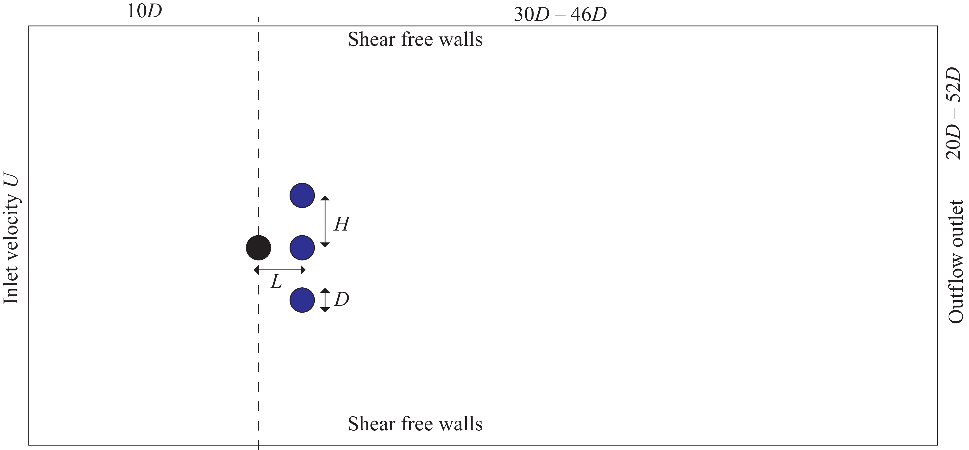


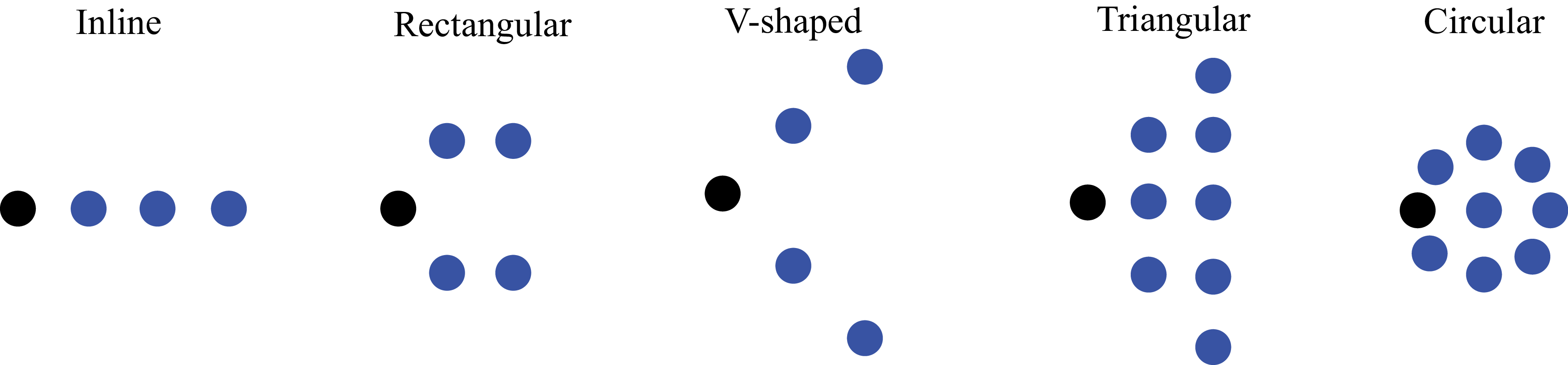
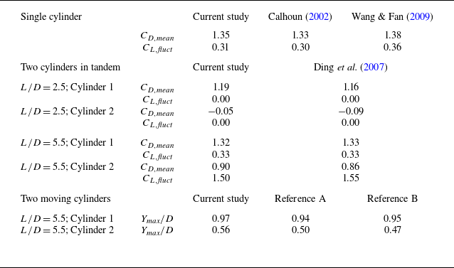
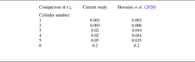


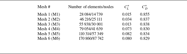

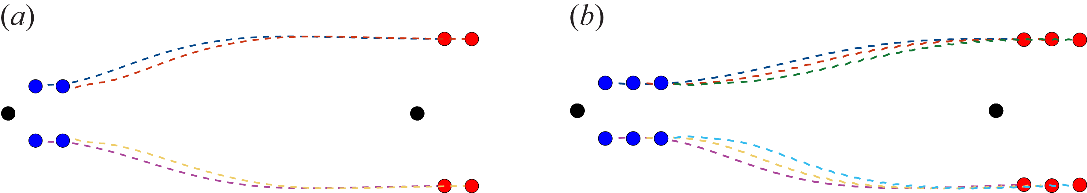


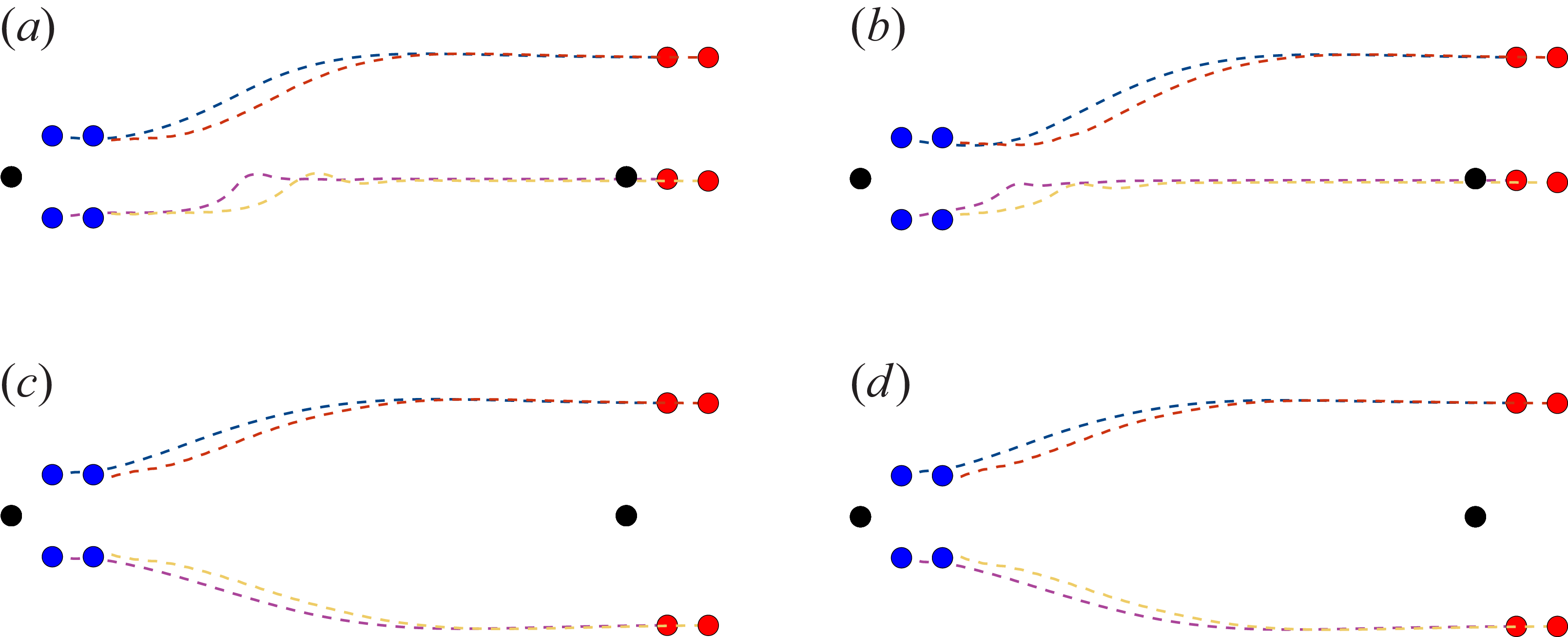


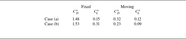
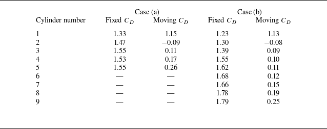
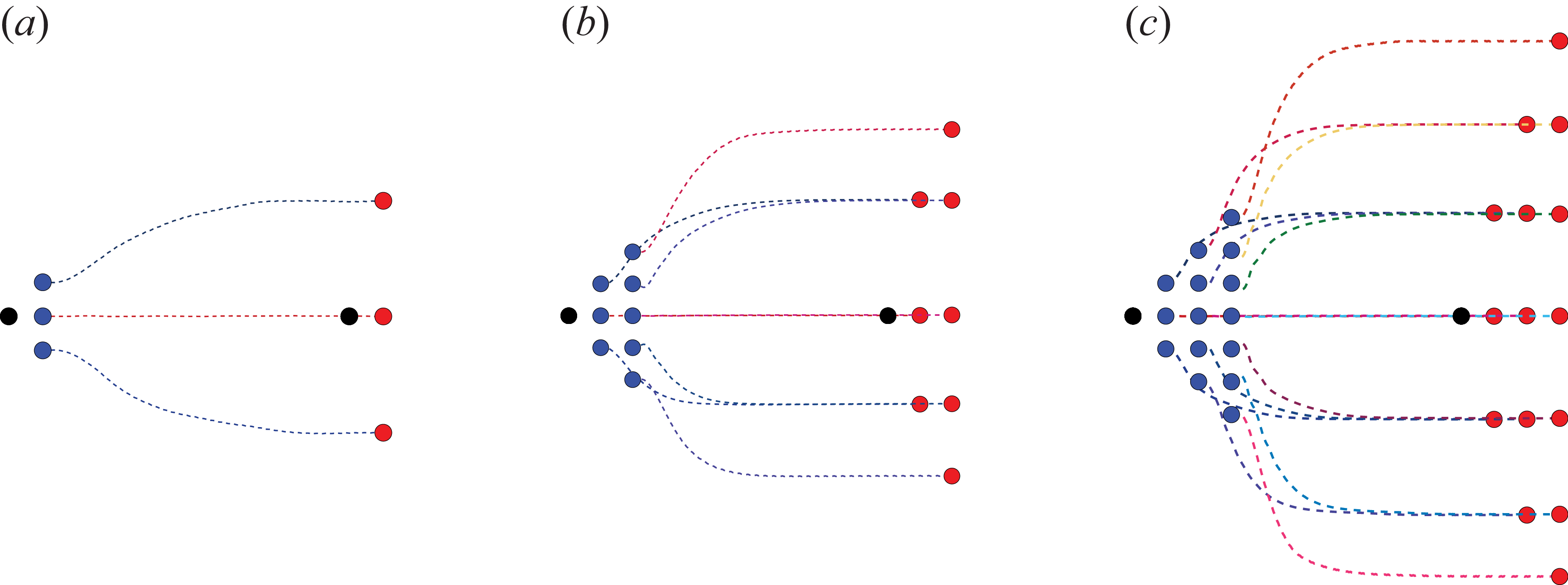

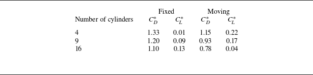
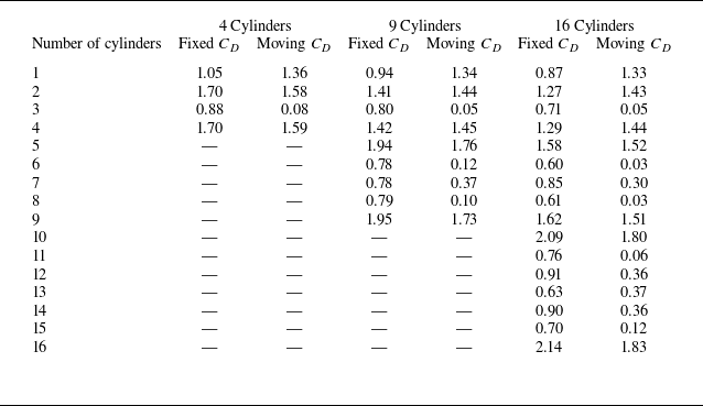
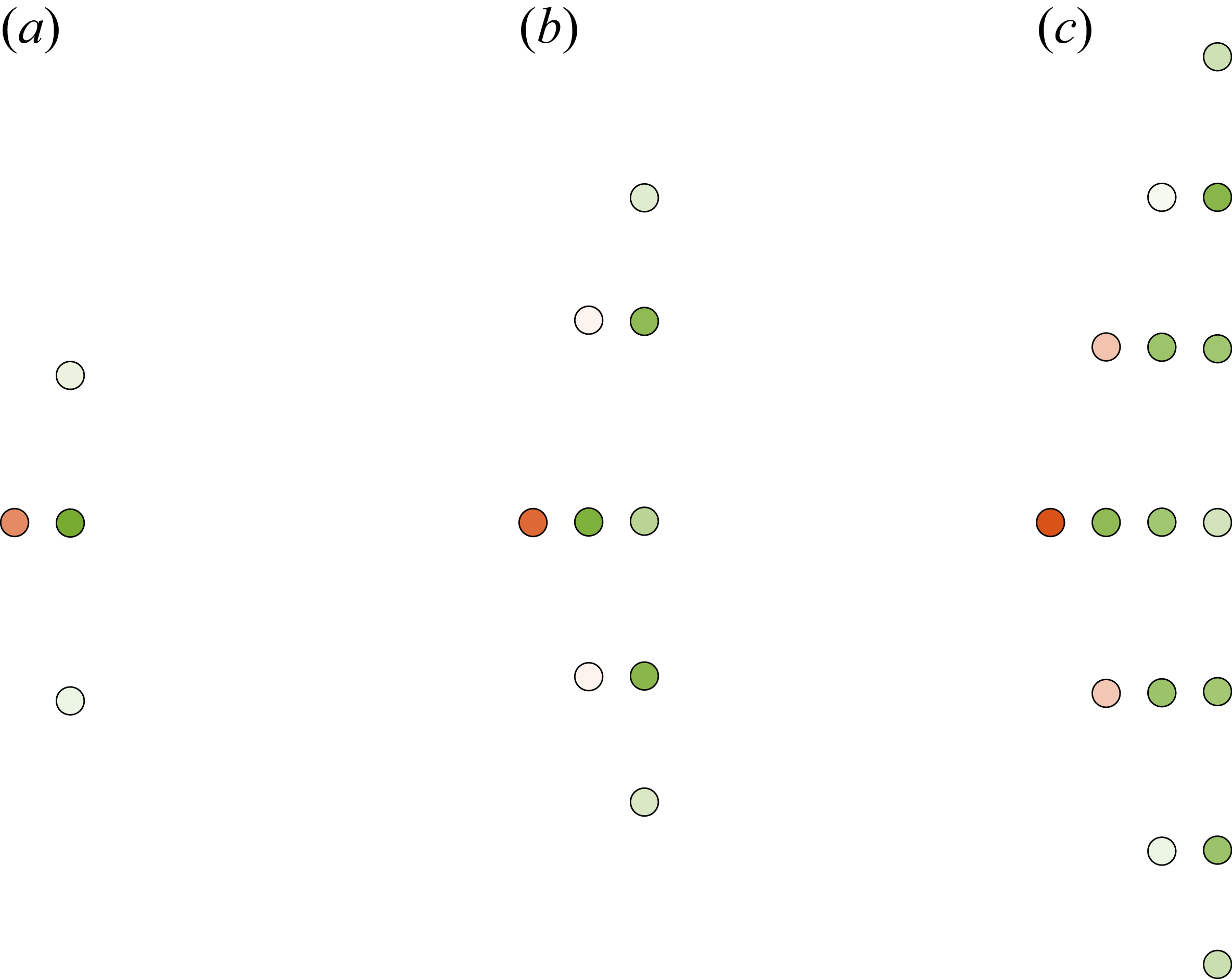
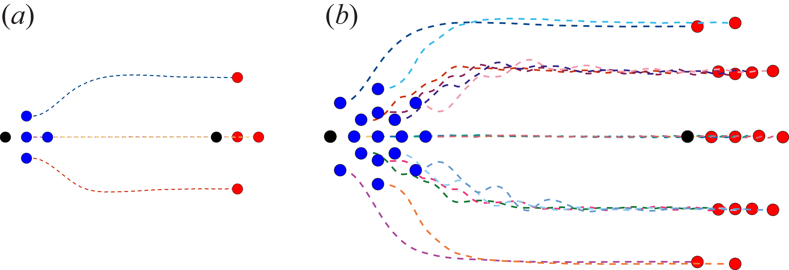
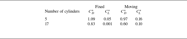


 Open access