


1 Introduction
The process of particle size segregation, whereby mixtures of different sized particles separate into distinct grain-size classes during flow, can be very pronounced, with experiments showing rapid vertical segregation into regions of nearly pure small and large particles (Savage & Lun Reference Savage and Lun1988; Vallance & Savage Reference Vallance, Savage, Rosato and Blackmore2000; Golick & Daniels Reference Golick and Daniels2009). When this is combined with periodic deposition it can lead to the formation of striking alternating stratified layers (Gray & Hutter Reference Gray and Hutter1997; Makse et al. Reference Makse, Havlin, King and Stanley1997; Gray & Ancey Reference Gray and Ancey2009) in heaps as well as petal-like patterns in rotating drums (Hill et al. Reference Hill, Kharkar, Gilchrist, McCarthy and Ottino1999; Gray & Chugunov Reference Gray and Chugunov2006; Zuriguel et al. Reference Zuriguel, Gray, Peixinho and Mullin2006). For dense granular flows, the dominant physical mechanisms driving segregation are thought to be kinetic sieving and squeeze expulsion (Middleton Reference Middleton and Lajoie1970; Savage & Lun Reference Savage and Lun1988; van der Vaart et al. Reference van der Vaart, Gajjar, Epely-Chauvin, Andreini, Gray and Ancey2015). As a polydisperse material is sheared, smaller particles are more likely to be able to percolate down through cavities that open up, which in turn exerts an upward force on the larger particles. Several models have been proposed to capture this effect (e.g. Bridgwater, Foo & Stephens Reference Bridgwater, Foo and Stephens1985; Savage & Lun Reference Savage and Lun1988; Dolgunin & Ukolov Reference Dolgunin and Ukolov1995; Gray & Thornton Reference Gray and Thornton2005; Gray & Chugunov Reference Gray and Chugunov2006; Gray & Ancey Reference Gray and Ancey2011; Marks, Rognon & Einav Reference Marks, Rognon and Einav2012; Gray & Ancey Reference Gray and Ancey2015) which all have a similar structure and describe the evolving particle size distribution for a given bulk flow. A recent review can be found in Gray, Gajjar & Kokelaar (Reference Gray, Gajjar and Kokelaar2015).
Field studies (e.g. Pierson Reference Pierson and Abrahams1986; Iverson Reference Iverson, Rickenmann and Chen2003; Lube et al. Reference Lube, Cronin, Platz, Freundt, Procter, Henderson and Sheridan2007) have provided strong evidence for the occurrence of particle size segregation in geophysical flows. In particular, debris flow deposits show self-organisation into leveed channels, with large particles being vertically segregated to the free surface, sheared to the flow front and then shouldered aside into coarse-grained static regions (Félix & Thomas Reference Félix and Thomas2004; Johnson et al. Reference Johnson, Kokelaar, Iverson, Logan, LaHusen and Gray2012). The finer material forms a lining on the inside wall of these lateral levees (Kokelaar et al. Reference Kokelaar, Graham, Gray and Vallance2014), which reduces the friction in the channel and enhances the mobility of the mixed interior. Experiments at the United States Geological Survey (USGS) debris flow flume in Oregon, USA (Johnson et al. Reference Johnson, Kokelaar, Iverson, Logan, LaHusen and Gray2012) as well as smaller-scale laboratory investigations (Deboeuf et al. Reference Deboeuf, Lajeunesse, Dauchot and Andreotti2006; Goujon, Dalloz-Dubrujeaud & Thomas Reference Goujon, Dalloz-Dubrujeaud and Thomas2007; Kokelaar et al. Reference Kokelaar, Graham, Gray and Vallance2014) have been able to reproduce these feedback effects, with runout distances for a bidisperse material being greater than for either type of particle in pure phase. A related phenomenon is the formation of segregation-induced fingering instabilities in granular free-surface flows (Pouliquen, Delour & Savage Reference Pouliquen, Delour and Savage1997; Pouliquen & Vallance Reference Pouliquen and Vallance1999; Aranson, Malloggi & Clement Reference Aranson, Malloggi and Clement2006; Malloggi et al. Reference Malloggi, Lanuza, Andreotti and Clément2006; Woodhouse et al. Reference Woodhouse, Thornton, Johnson, Kokelaar and Gray2012). These studies can be motivated by field observations of geophysical flows advancing as a series of lobate structures, for example the pyroclastic currents following the Mount St Helens eruption in July 1980 (figure 1).
Pyroclastic flow deposits from the eruption of Mount St Helens on July 22nd 1980 showing evidence of particle size segregation and finger formation during runout (Photo courtesy Dan Miller and USGS).

Experiments are carried out using a bidisperse mixture of spherical ballotini (white,
 $75{-}150~\unicode[STIX]{x03BC}\text{m}$
diameter) and angular carborundum (brown,
$75{-}150~\unicode[STIX]{x03BC}\text{m}$
diameter) and angular carborundum (brown,
 $305{-}355~\unicode[STIX]{x03BC}\text{m}$
) flowing down a plane inclined at
$305{-}355~\unicode[STIX]{x03BC}\text{m}$
) flowing down a plane inclined at
 $27^{\circ }$
, which is roughened by attaching a single layer of turquoise ballotini
$27^{\circ }$
, which is roughened by attaching a single layer of turquoise ballotini
 $(750{-}1000~\unicode[STIX]{x03BC}\text{m})$
to the base with double-sided tape (figure 2 and supplementary movie 1 available at https://doi.org/10.1017/jfm.2016.673). Initially well-mixed material is released from rest using a double gate system with an inflow height of 2 mm. As it flows down the slope, the large particles are segregated to the surface and preferentially sheared to the front. This front becomes unstable due to greater frictional forces and splits into a number of different channels, or fingers, with the internal structure of each finger resembling that of a single leveed channel.
$(750{-}1000~\unicode[STIX]{x03BC}\text{m})$
to the base with double-sided tape (figure 2 and supplementary movie 1 available at https://doi.org/10.1017/jfm.2016.673). Initially well-mixed material is released from rest using a double gate system with an inflow height of 2 mm. As it flows down the slope, the large particles are segregated to the surface and preferentially sheared to the front. This front becomes unstable due to greater frictional forces and splits into a number of different channels, or fingers, with the internal structure of each finger resembling that of a single leveed channel.
The time scales associated with this instability are relatively short, with the early traces of fingers beginning to appear after approximately 1 s. However, fingers only develop after the segregation of large particles to the free surface and subsequent accumulation at the front, and hence the fingering time scale must necessarily be slower than that of particle size segregation. There have been several attempts to calculate this segregation rate, for example in large-scale experimental debris flows, where Johnson et al. (Reference Johnson, Kokelaar, Iverson, Logan, LaHusen and Gray2012) found large particles rising at approximately
 $3.5~\text{cm}~\text{s}^{-1}$
, or 1 % of the typical bulk downslope velocity. In laboratory experiments of dry glass beads, Wiederseiner et al. (Reference Wiederseiner, Andreini, Epely-Chauvin, Moser, Monnereau, Gray and Ancey2011) measured percolation rates of
$3.5~\text{cm}~\text{s}^{-1}$
, or 1 % of the typical bulk downslope velocity. In laboratory experiments of dry glass beads, Wiederseiner et al. (Reference Wiederseiner, Andreini, Epely-Chauvin, Moser, Monnereau, Gray and Ancey2011) measured percolation rates of
 $1.5~\text{mm}~\text{s}^{-1}$
, compared to average bulk velocities of
$1.5~\text{mm}~\text{s}^{-1}$
, compared to average bulk velocities of
 $30~\text{mm}~\text{s}^{-1}$
. This ratio is consistent with the discrete element model (DEM) simulations used by Staron & Phillips (Reference Staron and Phillips2014) to calculate segregation time scales. Such segregation rates suggest that these thin flows (less than 2 mm, or approximately 10 particle diameters) rapidly segregate before the onset of the fingering instability.
$30~\text{mm}~\text{s}^{-1}$
. This ratio is consistent with the discrete element model (DEM) simulations used by Staron & Phillips (Reference Staron and Phillips2014) to calculate segregation time scales. Such segregation rates suggest that these thin flows (less than 2 mm, or approximately 10 particle diameters) rapidly segregate before the onset of the fingering instability.
There is an important distinction to be made between two different finger formation regimes that occur for different inflow conditions. For the experiments shown in figure 2 and movie 1, large quantities of granular material are loaded into the hopper, meaning grains are supplied at a constant flux for the entire observed duration. The resulting fingers are bounded by coarse-rich levees, and also have regions of pure carborundum at the rear of each channel wall, which are eroded by oncoming material from the inflow. This erosion process is particularly apparent in movie 1, where it can be seen that the ‘large particle islands’ creep downslope in a series of discrete surges. These islands move more slowly than the flow front, leading to finger elongation, although levees of adjacent fingers typically remain in contact. Figure 3(a) shows a close up of the experimental frontal zone, and a schematic of this behaviour is given by figure 4(a). The continuous inflow regime is representative of early fingering instability experiments (Pouliquen et al. Reference Pouliquen, Delour and Savage1997; Pouliquen & Vallance Reference Pouliquen and Vallance1999), whereas later work (Woodhouse et al. Reference Woodhouse, Thornton, Johnson, Kokelaar and Gray2012; Gray et al. Reference Gray, Gajjar and Kokelaar2015) used only a finite amount of material in the hopper. In this case the initial onset of finger formation is identical, but as the inflow stops and the supply wanes, erosion of the large particle islands ceases. These stationary regions then act as a barrier between adjacent channels, preventing contact and allowing distinct separated fingers to form as the remainder of the material lengthens the pre-existing fingers (figures 3 b and 4 b). This final phase can lead to unexpectedly long run-out distances, such as in figure 1, before eventually coming to rest and revealing the lubricating fine-grained levee lining (Kokelaar et al. Reference Kokelaar, Graham, Gray and Vallance2014).
Experiments on a plane inclined at
 $27^{\circ }$
using 80 % ballotini (white,
$27^{\circ }$
using 80 % ballotini (white,
 $75{-}150~\unicode[STIX]{x03BC}\text{m}$
), 20 % carborundum (brown,
$75{-}150~\unicode[STIX]{x03BC}\text{m}$
), 20 % carborundum (brown,
 $305{-}355~\unicode[STIX]{x03BC}\text{m}$
) released from rest through a double gate system of inflow thickness 2 mm. The chute is roughened with turquoise ballotini
$305{-}355~\unicode[STIX]{x03BC}\text{m}$
) released from rest through a double gate system of inflow thickness 2 mm. The chute is roughened with turquoise ballotini
 $(750{-}1000~\unicode[STIX]{x03BC}\text{m})$
. Images show snapshots at approximate times
$(750{-}1000~\unicode[STIX]{x03BC}\text{m})$
. Images show snapshots at approximate times
 $t=0.9~\text{s}$
,
$t=0.9~\text{s}$
,
 $t=2.6~\text{s}$
,
$t=2.6~\text{s}$
,
 $t=4.1~\text{s}$
,
$t=4.1~\text{s}$
,
 $t=6.0~\text{s}$
and
$t=6.0~\text{s}$
and
 $t=7.9~\text{s}$
. Supplementary movie 1 available online.
$t=7.9~\text{s}$
. Supplementary movie 1 available online.

Close ups of the experimental flow fronts for (a) a continuous supply of particles from the inflow gate and (b) a finite release of granular material, where the supply has already been cutoff. In both cases a bidisperse mixture of 80 % white ballotini
 $(75{-}150~\unicode[STIX]{x03BC}\text{m})$
, 20 % brown carborundum
$(75{-}150~\unicode[STIX]{x03BC}\text{m})$
, 20 % brown carborundum
 $(305{-}355~\unicode[STIX]{x03BC}\text{m})$
is used and the inflow thickness is 2 mm.
$(305{-}355~\unicode[STIX]{x03BC}\text{m})$
is used and the inflow thickness is 2 mm.

Schematic illustrating the difference between the initial onset of finger formation and fully developed fingers. (a) A continuous supply of material from the inflow gate causes the large particles at the back of the levees to be slowly eroded and move downstream. The front of the fingers propagates faster, meaning they lengthen over time, and adjacent fingers remain in contact with each other. (b) When the inflow is cutoff the regions at the rear of the levees come to rest and all remaining material flows down the pre-established channels. This leads to elongated distinct fingers with grain-free zones in between, which will eventually arrest as the flow wanes. In both diagrams shaded regions correspond to coarse-rich areas and dotted lines denote extent of the fingers at an earlier time.

Experiments on a plane inclined at
 $27^{\circ }$
using monodisperse granular material consisting of 100 % ballotini
$27^{\circ }$
using monodisperse granular material consisting of 100 % ballotini
 $(75{-}150~\unicode[STIX]{x03BC}\text{m})$
released from rest through a double gate system of inflow thickness 2 mm. Images show snapshots at approximate times
$(75{-}150~\unicode[STIX]{x03BC}\text{m})$
released from rest through a double gate system of inflow thickness 2 mm. Images show snapshots at approximate times
 $t=0.4~\text{s}$
,
$t=0.4~\text{s}$
,
 $t=1.7~\text{s}$
,
$t=1.7~\text{s}$
,
 $t=3.0~\text{s}$
,
$t=3.0~\text{s}$
,
 $t=4.3~\text{s}$
and
$t=4.3~\text{s}$
and
 $t=5.7~\text{s}$
. Note the time scales are shorter than the equivalent bidisperse experiments (figure 2) as pure small particles travel faster. Supplementary movie 2 available online.
$t=5.7~\text{s}$
. Note the time scales are shorter than the equivalent bidisperse experiments (figure 2) as pure small particles travel faster. Supplementary movie 2 available online.

Continuously supplied experiments are also conducted using a monodisperse flow of small ballotini (figure 5 and supplementary movie 2). There are some small irregularities as the front advances, most likely due to imperfections of the inflow layer and on the channel bed, as well as the formation of roll waves, but the same finger structures do not form and propagation is approximately uniform across the slope. This is consistent with the work of Pouliquen (Reference Pouliquen1999b
), who showed that a monodisperse granular front flows with a constant velocity and well-defined shape on a rough inclined plane. The process of finger formation is therefore driven by particle size segregation. Note that experiments using pure large particles do not flow at this slope inclination of 27
 $^{\circ }$
because the angular carborundum in pure phase is too resistive. This highlights another key component of the instability mechanism, which requires the larger particles to have a higher effective friction coefficient than the smaller ones. In natural flows, the interstitial pore pressure is dissipated more rapidly through large particles, meaning that large-particle-rich regions experience greater frictional forces, even if the particles themselves are not more angular like in the experiments shown here (Iverson Reference Iverson1997; Johnson et al.
Reference Johnson, Kokelaar, Iverson, Logan, LaHusen and Gray2012). The equivalent experiments have also been carried out using a bidisperse mixture of different sized spheres and a frontal instability does still form, although the resulting fingers have weaker, less stable levee walls. In this case the geometrical properties of the two spherical species are the same, but the large particles are slightly more resistive due to their interaction with the bed roughness (Goujon, Thomas & Dalloz-Dubrujeaud Reference Goujon, Thomas and Dalloz-Dubrujeaud2003). On the other hand, the fingering instability does not form in experiments using rough small particles and smooth large grains, where it is found that the larger particles shear off the top of the fines, which are deposited on the chute without the formation of fingers.
$^{\circ }$
because the angular carborundum in pure phase is too resistive. This highlights another key component of the instability mechanism, which requires the larger particles to have a higher effective friction coefficient than the smaller ones. In natural flows, the interstitial pore pressure is dissipated more rapidly through large particles, meaning that large-particle-rich regions experience greater frictional forces, even if the particles themselves are not more angular like in the experiments shown here (Iverson Reference Iverson1997; Johnson et al.
Reference Johnson, Kokelaar, Iverson, Logan, LaHusen and Gray2012). The equivalent experiments have also been carried out using a bidisperse mixture of different sized spheres and a frontal instability does still form, although the resulting fingers have weaker, less stable levee walls. In this case the geometrical properties of the two spherical species are the same, but the large particles are slightly more resistive due to their interaction with the bed roughness (Goujon, Thomas & Dalloz-Dubrujeaud Reference Goujon, Thomas and Dalloz-Dubrujeaud2003). On the other hand, the fingering instability does not form in experiments using rough small particles and smooth large grains, where it is found that the larger particles shear off the top of the fines, which are deposited on the chute without the formation of fingers.
The above observations suggest that any theoretical model should account for both the bulk flow and the effect of particle size segregation, in particular the relative frictional differences. Pouliquen & Vallance (Reference Pouliquen and Vallance1999) proposed a model for these segregation-mobility feedback effects in bidisperse granular flows based on their experimental work. Depth-averaged mass and momentum balance equations were coupled to the depth-averaged concentration (representing the distribution of large and small particles) through a basal friction law that was weighted according to the evolving composition. However, this work did not explicitly model the size-segregation process, instead prescribing an initial concentration distribution and allowing it to be advected with the bulk flow. The work of Gray & Kokelaar (Reference Gray and Kokelaar2010a ,Reference Gray and Kokelaar b ) in depth integrating previous three-dimensional segregation equations (e.g. Gray & Thornton Reference Gray and Thornton2005) allowed the development of fully coupled avalanche-segregation models. This was exploited by Woodhouse et al. (Reference Woodhouse, Thornton, Johnson, Kokelaar and Gray2012), where the coupling was achieved through a concentration-dependent version of Pouliquen’s (Reference Pouliquen1999a ) friction law. This model was able to capture the qualitative features of spontaneous leveed finger formation, but the authors showed that, at a critical concentration, the equations were mathematically ill posed in the sense of Joseph & Saut (Reference Joseph and Saut1990), i.e. a linear stability analysis produced unbounded growth rates in the high wavenumber limit. The critical Froude number at which this occurred corresponded to where one of the characteristics of the shallow water equations coincided with that from the large particle transport equation (Gray & Kokelaar Reference Gray and Kokelaar2010a ,Reference Gray and Kokelaar b ) and the system loses strict hyperbolicity. Consequently, at a specific concentration any numerical grid-scale noise grows unboundedly as the grid size tends to zero and the ill posedness manifests itself in the form of grid-dependent simulations, with the number of fingers being governed by the numerical viscosity.
The Woodhouse et al. (Reference Woodhouse, Thornton, Johnson, Kokelaar and Gray2012) model suggests that additional physics is required to regularise the depth-averaged governing equations. Gray & Edwards (Reference Gray and Edwards2014) recently devised a strategy to achieve this using the
 $\unicode[STIX]{x1D707}(I)$
-rheology for dense granular flows (GDR MiDi 2004; da Cruz et al.
Reference da Cruz, Emam, Prochnow, Roux and Chevoir2005; Jop, Forterre & Pouliquen Reference Jop, Forterre and Pouliquen2005, Reference Jop, Forterre and Pouliquen2006). To leading order, they showed that this three-dimensional constitutive law only contributed via an effective basal friction, equivalent to the dynamic friction law for rough beds (Pouliquen Reference Pouliquen1999a
; Pouliquen & Forterre Reference Pouliquen and Forterre2002), and the depth-averaged equations reduce to a standard hyperbolic avalanche model (e.g. Gray, Tai & Noelle Reference Gray, Tai and Noelle2003). Using the steady uniform Bagnold velocity and lithostatic pressure profiles (GDR MiDi 2004) they were able to include the gradient of the depth-averaged in-plane deviatoric stress into the downstream momentum balance. These higher-order viscous terms represent a singular perturbation to the system and in many situations they can be neglected. However, strong evidence for their inclusion is provided by roll waves, where the standard shallow water avalanche equations are unable to predict the cutoff frequency observed in experiments (Forterre & Pouliquen Reference Forterre and Pouliquen2003). With viscous terms, the depth-averaged
$\unicode[STIX]{x1D707}(I)$
-rheology for dense granular flows (GDR MiDi 2004; da Cruz et al.
Reference da Cruz, Emam, Prochnow, Roux and Chevoir2005; Jop, Forterre & Pouliquen Reference Jop, Forterre and Pouliquen2005, Reference Jop, Forterre and Pouliquen2006). To leading order, they showed that this three-dimensional constitutive law only contributed via an effective basal friction, equivalent to the dynamic friction law for rough beds (Pouliquen Reference Pouliquen1999a
; Pouliquen & Forterre Reference Pouliquen and Forterre2002), and the depth-averaged equations reduce to a standard hyperbolic avalanche model (e.g. Gray, Tai & Noelle Reference Gray, Tai and Noelle2003). Using the steady uniform Bagnold velocity and lithostatic pressure profiles (GDR MiDi 2004) they were able to include the gradient of the depth-averaged in-plane deviatoric stress into the downstream momentum balance. These higher-order viscous terms represent a singular perturbation to the system and in many situations they can be neglected. However, strong evidence for their inclusion is provided by roll waves, where the standard shallow water avalanche equations are unable to predict the cutoff frequency observed in experiments (Forterre & Pouliquen Reference Forterre and Pouliquen2003). With viscous terms, the depth-averaged
 $\unicode[STIX]{x1D707}(I)$
-rheology is able to predict this cutoff for a wide range of Froude numbers and slope angles without any fitting parameters (Gray & Edwards Reference Gray and Edwards2014).
$\unicode[STIX]{x1D707}(I)$
-rheology is able to predict this cutoff for a wide range of Froude numbers and slope angles without any fitting parameters (Gray & Edwards Reference Gray and Edwards2014).
In addition, Edwards & Gray (Reference Edwards and Gray2015) showed that the extra terms play a crucial role in the formation of steadily propagating erosion–deposition waves on erodible beds. Baker, Barker & Gray (Reference Baker, Barker and Gray2016) recently proposed a two-dimensional extension of the equations to account for lateral variation, and applied the model to steady uniform channel flows. The generalised viscous terms give rise to downslope velocities with cross-slope profiles, another physical feature not captured by classical shallow-water models. These very promising results for monodisperse flows suggest that Gray & Edwards’ (Reference Gray and Edwards2014) depth-averaged
 $\unicode[STIX]{x1D707}(I)$
-rheology could provide the dissipative mechanism to regularise the depth-averaged segregation-mobility feedback equations. This paper therefore describes how to generalise their work into a bidisperse set-up, and shows that the resulting model is mathematically well posed. A two-dimensional (downslope and lateral) extension of the system of equations, based on the work of Baker et al. (Reference Baker, Barker and Gray2016), admits numerical solutions showing the formation of fingering instabilities on an inclined plane, with the key finger characteristics being independent of the grid resolution and controlled by the newly introduced physical viscosity.
$\unicode[STIX]{x1D707}(I)$
-rheology could provide the dissipative mechanism to regularise the depth-averaged segregation-mobility feedback equations. This paper therefore describes how to generalise their work into a bidisperse set-up, and shows that the resulting model is mathematically well posed. A two-dimensional (downslope and lateral) extension of the system of equations, based on the work of Baker et al. (Reference Baker, Barker and Gray2016), admits numerical solutions showing the formation of fingering instabilities on an inclined plane, with the key finger characteristics being independent of the grid resolution and controlled by the newly introduced physical viscosity.
2 A depth-averaged model for particle size-segregation
Consider a Cartesian coordinate system
 $Oxz$
with the
$Oxz$
with the
 $x$
-axis pointing downslope at an angle
$x$
-axis pointing downslope at an angle
 $\unicode[STIX]{x1D701}$
to the horizontal and the
$\unicode[STIX]{x1D701}$
to the horizontal and the
 $z$
-axis being the upward pointing normal (figure 6). A bidisperse mass of granular material is assumed to lie between a free surface at
$z$
-axis being the upward pointing normal (figure 6). A bidisperse mass of granular material is assumed to lie between a free surface at
 $z=s(x,t)$
and rigid base at
$z=s(x,t)$
and rigid base at
 $z=b(x)$
, so that the flow thickness is
$z=b(x)$
, so that the flow thickness is
 $h(x,t)=s-b$
. Denoting the volume fraction of small particles as
$h(x,t)=s-b$
. Denoting the volume fraction of small particles as
 $\unicode[STIX]{x1D719}\in [0,1]$
(so that the proportion of large particles is
$\unicode[STIX]{x1D719}\in [0,1]$
(so that the proportion of large particles is
 $1-\unicode[STIX]{x1D719}$
), the evolving concentration distribution can be modelled by a general segregation-diffusive-remixing equation (e.g. Bridgwater Reference Bridgwater1976; Savage & Lun Reference Savage and Lun1988; Dolgunin & Ukolov Reference Dolgunin and Ukolov1995; Gray & Chugunov Reference Gray and Chugunov2006; Gray & Ancey Reference Gray and Ancey2011; Gajjar & Gray Reference Gajjar and Gray2014),
$1-\unicode[STIX]{x1D719}$
), the evolving concentration distribution can be modelled by a general segregation-diffusive-remixing equation (e.g. Bridgwater Reference Bridgwater1976; Savage & Lun Reference Savage and Lun1988; Dolgunin & Ukolov Reference Dolgunin and Ukolov1995; Gray & Chugunov Reference Gray and Chugunov2006; Gray & Ancey Reference Gray and Ancey2011; Gajjar & Gray Reference Gajjar and Gray2014),
 $$\begin{eqnarray}\displaystyle \frac{\unicode[STIX]{x2202}\unicode[STIX]{x1D719}}{\unicode[STIX]{x2202}t}+\frac{\unicode[STIX]{x2202}}{\unicode[STIX]{x2202}x}(\unicode[STIX]{x1D719}u)+\frac{\unicode[STIX]{x2202}}{\unicode[STIX]{x2202}z}(\unicode[STIX]{x1D719}w)-\frac{\unicode[STIX]{x2202}}{\unicode[STIX]{x2202}z}(Q(\unicode[STIX]{x1D719}))=\frac{\unicode[STIX]{x2202}}{\unicode[STIX]{x2202}z}\left(D\frac{\unicode[STIX]{x2202}\unicode[STIX]{x1D719}}{\unicode[STIX]{x2202}z}\right), & & \displaystyle\end{eqnarray}$$
where the bulk velocity
 $\boldsymbol{u}$
has components
$\boldsymbol{u}$
has components
 $(u,w)$
in the downslope and normal directions respectively. The first three terms on the left-hand side represent the advection of the concentration with the bulk flow, whereas the fourth term accounts for vertical segregation. The flux function
$(u,w)$
in the downslope and normal directions respectively. The first three terms on the left-hand side represent the advection of the concentration with the bulk flow, whereas the fourth term accounts for vertical segregation. The flux function
 $Q(\unicode[STIX]{x1D719})\geqslant 0$
satisfies
$Q(\unicode[STIX]{x1D719})\geqslant 0$
satisfies
 $Q(0)=Q(1)=0$
to ensure the segregation mechanism shuts off in the monodisperse limits. Different functional forms for
$Q(0)=Q(1)=0$
to ensure the segregation mechanism shuts off in the monodisperse limits. Different functional forms for
 $Q$
have been proposed, including a simple quadratic
$Q$
have been proposed, including a simple quadratic
 $Q(\unicode[STIX]{x1D719})=q\unicode[STIX]{x1D719}(1-\unicode[STIX]{x1D719})$
, (Gray & Thornton Reference Gray and Thornton2005) or skewed cubic
$Q(\unicode[STIX]{x1D719})=q\unicode[STIX]{x1D719}(1-\unicode[STIX]{x1D719})$
, (Gray & Thornton Reference Gray and Thornton2005) or skewed cubic
 $Q(\unicode[STIX]{x1D719})=q\unicode[STIX]{x1D719}(1-\unicode[STIX]{x1D719})(1-\unicode[STIX]{x1D6FE}\unicode[STIX]{x1D719})$
, (Gajjar & Gray Reference Gajjar and Gray2014; van der Vaart et al.
Reference van der Vaart, Gajjar, Epely-Chauvin, Andreini, Gray and Ancey2015) the latter being motivated by experimental observations of asymmetric segregation, which has also been found from discrete particle method simulations (Tunuguntla, Bokhove & Thornton Reference Tunuguntla, Bokhove and Thornton2014). The exact dependence will not be important in this paper. The right-hand side of (2.1) represents diffusive remixing, where the diffusivity
$Q(\unicode[STIX]{x1D719})=q\unicode[STIX]{x1D719}(1-\unicode[STIX]{x1D719})(1-\unicode[STIX]{x1D6FE}\unicode[STIX]{x1D719})$
, (Gajjar & Gray Reference Gajjar and Gray2014; van der Vaart et al.
Reference van der Vaart, Gajjar, Epely-Chauvin, Andreini, Gray and Ancey2015) the latter being motivated by experimental observations of asymmetric segregation, which has also been found from discrete particle method simulations (Tunuguntla, Bokhove & Thornton Reference Tunuguntla, Bokhove and Thornton2014). The exact dependence will not be important in this paper. The right-hand side of (2.1) represents diffusive remixing, where the diffusivity
 $D$
may, in general, depend on the flow variables.
$D$
may, in general, depend on the flow variables.
A schematic diagram of the coordinate axes
 $Oxz$
inclined at an angle
$Oxz$
inclined at an angle
 $\unicode[STIX]{x1D701}$
to the horizontal, so that the
$\unicode[STIX]{x1D701}$
to the horizontal, so that the
 $x$
-axis points downslope and the
$x$
-axis points downslope and the
 $z$
-axis is the upward pointing normal. The granular material lies between the base
$z$
-axis is the upward pointing normal. The granular material lies between the base
 $z=b(x)$
and free surface
$z=b(x)$
and free surface
 $z=s(x,t)$
, giving a flow thickness
$z=s(x,t)$
, giving a flow thickness
 $h(x,t)=s-b$
. At
$h(x,t)=s-b$
. At
 $z=l(x,t)$
there is an interface separating a layer of pure small particles (
$z=l(x,t)$
there is an interface separating a layer of pure small particles (
 $\unicode[STIX]{x1D719}=1$
) of thickness
$\unicode[STIX]{x1D719}=1$
) of thickness
 $\unicode[STIX]{x1D702}(x,t)=l-b$
at the bottom of the flow from a layer of pure large particles (
$\unicode[STIX]{x1D702}(x,t)=l-b$
at the bottom of the flow from a layer of pure large particles (
 $\unicode[STIX]{x1D719}=0$
) lying on top.
$\unicode[STIX]{x1D719}=0$
) lying on top.

The segregation equation (2.1) is subject to kinematic boundary conditions,
 $$\begin{eqnarray}\displaystyle & \displaystyle u_{b}\frac{\unicode[STIX]{x2202}b}{\unicode[STIX]{x2202}x}-w_{b}=0,\quad \text{at }z=b(x), & \displaystyle\end{eqnarray}$$
 $$\begin{eqnarray}\displaystyle & \displaystyle \frac{\unicode[STIX]{x2202}s}{\unicode[STIX]{x2202}t}+u_{s}\frac{\unicode[STIX]{x2202}s}{\unicode[STIX]{x2202}x}-w_{s}=0,\quad \text{at }z=s(x,t), & \displaystyle\end{eqnarray}$$
 $b$
and
$b$
and
 $s$
denote evaluation of the velocity field at the base and free surface respectively. In addition, there is no flux of either large or small particles across the boundaries, i.e.
$s$
denote evaluation of the velocity field at the base and free surface respectively. In addition, there is no flux of either large or small particles across the boundaries, i.e.  $$\begin{eqnarray}\displaystyle Q(\unicode[STIX]{x1D719})+D\frac{\unicode[STIX]{x2202}\unicode[STIX]{x1D719}}{\unicode[STIX]{x2202}z}=0,\quad \text{at }z=b(x)\text{ and }z=s(x,t). & & \displaystyle\end{eqnarray}$$
Following Gray & Kokelaar (Reference Gray and Kokelaar2010a ,Reference Gray and Kokelaar b ), the segregation-diffusive-remixing equation (2.1) may be integrated through the avalanche thickness using Leibniz’ rule (Abramowitz & Stegun Reference Abramowitz and Stegun1970) to interchange the order of differentiation and integration, giving
 $$\begin{eqnarray}\displaystyle \frac{\unicode[STIX]{x2202}}{\unicode[STIX]{x2202}t}(h\bar{\unicode[STIX]{x1D719}})+\frac{\unicode[STIX]{x2202}}{\unicode[STIX]{x2202}x}(h\overline{\unicode[STIX]{x1D719}u})-\left[\unicode[STIX]{x1D719}\left(\frac{\unicode[STIX]{x2202}z}{\unicode[STIX]{x2202}t}+u\frac{\unicode[STIX]{x2202}z}{\unicode[STIX]{x2202}x}-w\right)\right]_{b}^{s}=\left[Q(\unicode[STIX]{x1D719})+D\frac{\unicode[STIX]{x2202}\unicode[STIX]{x1D719}}{\unicode[STIX]{x2202}z}\right]_{b}^{s}, & & \displaystyle\end{eqnarray}$$
where
 $$\begin{eqnarray}\displaystyle \bar{\unicode[STIX]{x1D719}}=\frac{1}{h}\int _{b}^{s}\unicode[STIX]{x1D719}\,\text{d}z,\quad \overline{\unicode[STIX]{x1D719}u}=\frac{1}{h}\int _{b}^{s}\unicode[STIX]{x1D719}u\,\text{d}z, & & \displaystyle\end{eqnarray}$$
are the depth-averaged small particle concentration and small particle flux respectively. The kinematic and no-flux boundary conditions (2.2)–(2.4), ensure that the square-bracketed terms disappear and the depth-integrated segregation equation (2.5) reduces to
 $$\begin{eqnarray}\displaystyle \frac{\unicode[STIX]{x2202}}{\unicode[STIX]{x2202}t}(h\bar{\unicode[STIX]{x1D719}})+\frac{\unicode[STIX]{x2202}}{\unicode[STIX]{x2202}x}(h\overline{\unicode[STIX]{x1D719}u})=0. & & \displaystyle\end{eqnarray}$$
The model is closed by deriving expressions relating the depth-averaged concentration flux to the depth-averaged downslope velocity, the latter being defined analogously to (2.6) as
 $$\begin{eqnarray}\displaystyle \bar{u}(x,t)=\frac{1}{h}\int _{b}^{s}u(x,z,t)\,\text{d}z. & & \displaystyle\end{eqnarray}$$
Since bidisperse flows have been observed to rapidly segregate into inversely graded layers (Gray & Hutter Reference Gray and Hutter1997; Gray & Ancey Reference Gray and Ancey2009), Gray & Kokelaar (Reference Gray and Kokelaar2010a ,Reference Gray and Kokelaar b ) suggested using a concentration profile
 $$\begin{eqnarray}\displaystyle \unicode[STIX]{x1D719}=\left\{\begin{array}{@{}ll@{}}0,\quad & l<z<s,\\ 1,\quad & b<z<l,\end{array}\right. & & \displaystyle\end{eqnarray}$$
representing a layer of pure small particles lying on top of a layer of pure large particles, where
 $z=l(x,t)$
denotes the height of the separating interface. In addition, the bulk velocity is assumed to take the form
$z=l(x,t)$
denotes the height of the separating interface. In addition, the bulk velocity is assumed to take the form
 $$\begin{eqnarray}\displaystyle u(x,z,t)=\bar{u}(x,t)f(\hat{z}), & & \displaystyle\end{eqnarray}$$
where
 $\hat{z}=(z-b)/h$
is the rescaled vertical coordinate and
$\hat{z}=(z-b)/h$
is the rescaled vertical coordinate and
 $f$
is the vertical shear profile, which should be an increasing function to ensure surface velocities are greater than those at the base and should also satisfy
$f$
is the vertical shear profile, which should be an increasing function to ensure surface velocities are greater than those at the base and should also satisfy
 $$\begin{eqnarray}\displaystyle \int _{0}^{1}f(\hat{z})\,\text{d}\hat{z}=1, & & \displaystyle\end{eqnarray}$$
to be consistent with the definition (2.8). Gray & Kokelaar (Reference Gray and Kokelaar2010a ,Reference Gray and Kokelaar b ) used families of linear shear profiles given by
 $$\begin{eqnarray}\displaystyle f(\hat{z})=f_{L}(\hat{z})\equiv \unicode[STIX]{x1D6FC}+2(1-\unicode[STIX]{x1D6FC})\hat{z}, & & \displaystyle\end{eqnarray}$$
to derive their depth-averaged segregation equation, where the parameter
 $\unicode[STIX]{x1D6FC}\in [0,1]$
controls the relative amount of shear and basal slip. These were also employed by Johnson et al. (Reference Johnson, Kokelaar, Iverson, Logan, LaHusen and Gray2012) to reconstruct the full velocity field at the USGS flume. Whilst simple linear profiles capture the basic features of the flow, a more physically accurate choice is the Bagnold velocity profile,
$\unicode[STIX]{x1D6FC}\in [0,1]$
controls the relative amount of shear and basal slip. These were also employed by Johnson et al. (Reference Johnson, Kokelaar, Iverson, Logan, LaHusen and Gray2012) to reconstruct the full velocity field at the USGS flume. Whilst simple linear profiles capture the basic features of the flow, a more physically accurate choice is the Bagnold velocity profile,
 $$\begin{eqnarray}\displaystyle f(\hat{z})=f_{B}(\hat{z})\equiv {\textstyle \frac{5}{3}}(1-(1-\hat{z})^{3/2}), & & \displaystyle\end{eqnarray}$$
which can be derived as the steady uniform solution to the three-dimensional
 $\unicode[STIX]{x1D707}(I)$
-rheology for granular flows (e.g. GDR MiDi 2004; Gray & Edwards Reference Gray and Edwards2014). Substituting the inversely graded concentration (2.9) and velocity profile (2.10) into the flux integral in (2.6) gives
$\unicode[STIX]{x1D707}(I)$
-rheology for granular flows (e.g. GDR MiDi 2004; Gray & Edwards Reference Gray and Edwards2014). Substituting the inversely graded concentration (2.9) and velocity profile (2.10) into the flux integral in (2.6) gives
 $$\begin{eqnarray}\displaystyle \overline{\unicode[STIX]{x1D719}u}=\frac{1}{h}\int _{b}^{l}u\,\text{d}z=\bar{u}\int _{0}^{\bar{\unicode[STIX]{x1D719}}}f(\hat{z})\,\text{d}\hat{z}, & & \displaystyle\end{eqnarray}$$
which may then be inserted into the depth-integrated segregation equation (2.7) to give
 $$\begin{eqnarray}\displaystyle \frac{\unicode[STIX]{x2202}}{\unicode[STIX]{x2202}t}(h\bar{\unicode[STIX]{x1D719}})+\frac{\unicode[STIX]{x2202}}{\unicode[STIX]{x2202}x}(h\bar{\unicode[STIX]{x1D719}}\bar{u})-\frac{\unicode[STIX]{x2202}}{\unicode[STIX]{x2202}x}(h\bar{u}G(\bar{\unicode[STIX]{x1D719}}))=0, & & \displaystyle\end{eqnarray}$$
where
 $$\begin{eqnarray}\displaystyle G(\bar{\unicode[STIX]{x1D719}})=\bar{\unicode[STIX]{x1D719}}-\int _{0}^{\bar{\unicode[STIX]{x1D719}}}f(\hat{z})\,\text{d}\hat{z}. & & \displaystyle\end{eqnarray}$$
The first two terms in (2.15) represent advection of the depth-averaged concentration with the bulk flow, and the third term captures the preferential shearing of the large particles to the flow front (the minus sign implies that fines are transported to the rear). For this reason it is referred to as the ‘large particle transport equation’ and is a more general version of that derived by Gray & Kokelaar (Reference Gray and Kokelaar2010a
,Reference Gray and Kokelaar
b
) and Woodhouse et al. (Reference Woodhouse, Thornton, Johnson, Kokelaar and Gray2012). The form of the ‘transport function’
 $G$
depends on the choice of shear profile, with the linear shear profile (2.12) leading to the quadratic
$G$
depends on the choice of shear profile, with the linear shear profile (2.12) leading to the quadratic
 $$\begin{eqnarray}\displaystyle G(\bar{\unicode[STIX]{x1D719}})=G_{L}(\bar{\unicode[STIX]{x1D719}})\equiv (1-\unicode[STIX]{x1D6FC})\bar{\unicode[STIX]{x1D719}}(1-\bar{\unicode[STIX]{x1D719}}), & & \displaystyle\end{eqnarray}$$
as in Gray & Kokelaar (Reference Gray and Kokelaar2010a ), and the Bagnold shear profile (2.13) giving
 $$\begin{eqnarray}\displaystyle G_{B}(\bar{\unicode[STIX]{x1D719}})\equiv {\textstyle \frac{2}{3}}(1-\bar{\unicode[STIX]{x1D719}})(1-(1-\bar{\unicode[STIX]{x1D719}})^{3/2}). & & \displaystyle\end{eqnarray}$$
The functions (2.17) and (2.18) have similar forms, with both satisfying
 $G(0)=G(1)=0$
, meaning the concentration is simply advected at the same speed as the bulk flow in both of the monodisperse limits. The Bagnold transport function (2.18) is skewed slightly towards smaller concentrations of small particles. However, the difference is relatively small (
$G(0)=G(1)=0$
, meaning the concentration is simply advected at the same speed as the bulk flow in both of the monodisperse limits. The Bagnold transport function (2.18) is skewed slightly towards smaller concentrations of small particles. However, the difference is relatively small (
 ${<}$
7 % of the maximum amplitude) and (2.18) may be approximated using a quadratic of the form (2.17) (figure 7). A value
${<}$
7 % of the maximum amplitude) and (2.18) may be approximated using a quadratic of the form (2.17) (figure 7). A value
 $\unicode[STIX]{x1D6FC}=1/7$
is chosen to ensure that the total area under the two curves, and hence the mean transport rate across all different concentrations, is the same, and such a fitted quadratic for
$\unicode[STIX]{x1D6FC}=1/7$
is chosen to ensure that the total area under the two curves, and hence the mean transport rate across all different concentrations, is the same, and such a fitted quadratic for
 $G$
shall be assumed throughout this paper. This makes subsequent computations more straightforward, since the
$G$
shall be assumed throughout this paper. This makes subsequent computations more straightforward, since the
 $(1-\bar{\unicode[STIX]{x1D719}})^{3/2}$
term in (2.18) results in complex values if round-off errors cause
$(1-\bar{\unicode[STIX]{x1D719}})^{3/2}$
term in (2.18) results in complex values if round-off errors cause
 $\bar{\unicode[STIX]{x1D719}}$
to be slightly greater than unity. Though the linear profile (2.12) with
$\bar{\unicode[STIX]{x1D719}}$
to be slightly greater than unity. Though the linear profile (2.12) with
 $\unicode[STIX]{x1D6FC}=1/7$
is qualitatively different to the Bagnold shear (2.13) due to the non-zero basal slip velocity, the remainder of this work does not distinguish between the velocity at different vertical positions, meaning this simplification is appropriate when dealing with depth-averaged quantities.
$\unicode[STIX]{x1D6FC}=1/7$
is qualitatively different to the Bagnold shear (2.13) due to the non-zero basal slip velocity, the remainder of this work does not distinguish between the velocity at different vertical positions, meaning this simplification is appropriate when dealing with depth-averaged quantities.
(a) Plots of the linear (2.12) and Bagnold (2.13) shear profiles
 $f(\hat{z})$
. (b) The corresponding transport functions
$f(\hat{z})$
. (b) The corresponding transport functions
 $G(\bar{\unicode[STIX]{x1D719}})$
given by (2.17) and (2.18) respectively. The value
$G(\bar{\unicode[STIX]{x1D719}})$
given by (2.17) and (2.18) respectively. The value
 $\unicode[STIX]{x1D6FC}=1/7$
is chosen for the linear profiles so that the area under the curves in (b) is the same.
$\unicode[STIX]{x1D6FC}=1/7$
is chosen for the linear profiles so that the area under the curves in (b) is the same.

Note the similar structure of the original segregation equation (2.1) and the large particle transport equation (2.15), with the vertical segregation in the former being replaced by lateral segregation in the latter. Also note that it is possible to reformulate (2.15) in terms of the small particle layer thickness,
 $\unicode[STIX]{x1D702}(x,t)=l-b$
, using the fact that
$\unicode[STIX]{x1D702}(x,t)=l-b$
, using the fact that
 $\unicode[STIX]{x1D702}=h\bar{\unicode[STIX]{x1D719}}$
, or the thickness of the large particle layer,
$\unicode[STIX]{x1D702}=h\bar{\unicode[STIX]{x1D719}}$
, or the thickness of the large particle layer,
 $\unicode[STIX]{x1D705}(x,t)=h-\unicode[STIX]{x1D702}$
, as described in Gray & Kokelaar (Reference Gray and Kokelaar2010a
,Reference Gray and Kokelaar
b
). Here it shall be left in terms of the depth-averaged concentration of small particles
$\unicode[STIX]{x1D705}(x,t)=h-\unicode[STIX]{x1D702}$
, as described in Gray & Kokelaar (Reference Gray and Kokelaar2010a
,Reference Gray and Kokelaar
b
). Here it shall be left in terms of the depth-averaged concentration of small particles
 $\bar{\unicode[STIX]{x1D719}}$
because this is more representative of what would actually be seen in overhead views of bidisperse experiments.
$\bar{\unicode[STIX]{x1D719}}$
because this is more representative of what would actually be seen in overhead views of bidisperse experiments.
3 Segregation-mobility coupling
The large particle transport equation (2.15) may be solved for the depth-averaged concentration
 $\bar{\unicode[STIX]{x1D719}}$
for a prescribed flow thickness
$\bar{\unicode[STIX]{x1D719}}$
for a prescribed flow thickness
 $h$
and bulk velocity
$h$
and bulk velocity
 $\bar{u}$
(e.g. Gray & Kokelaar Reference Gray and Kokelaar2010a
,Reference Gray and Kokelaar
b
). In some cases
$\bar{u}$
(e.g. Gray & Kokelaar Reference Gray and Kokelaar2010a
,Reference Gray and Kokelaar
b
). In some cases
 $h$
and
$h$
and
 $\bar{u}$
can be inferred from experimental measurements (Johnson et al.
Reference Johnson, Kokelaar, Iverson, Logan, LaHusen and Gray2012) but typically they are unknown and need to be solved for as part of the problem. Furthermore, it is expected that the evolving concentration distribution will feed back on the bulk motion and this coupling should be built into the model. The equations representing conservation of mass and momentum for the bulk flow are (Gray & Edwards Reference Gray and Edwards2014)
$\bar{u}$
can be inferred from experimental measurements (Johnson et al.
Reference Johnson, Kokelaar, Iverson, Logan, LaHusen and Gray2012) but typically they are unknown and need to be solved for as part of the problem. Furthermore, it is expected that the evolving concentration distribution will feed back on the bulk motion and this coupling should be built into the model. The equations representing conservation of mass and momentum for the bulk flow are (Gray & Edwards Reference Gray and Edwards2014)
 $$\begin{eqnarray}\displaystyle & \displaystyle \frac{\unicode[STIX]{x2202}h}{\unicode[STIX]{x2202}t}+\frac{\unicode[STIX]{x2202}}{\unicode[STIX]{x2202}x}(h\bar{u})=0, & \displaystyle\end{eqnarray}$$
 $$\begin{eqnarray}\displaystyle & \displaystyle \frac{\unicode[STIX]{x2202}}{\unicode[STIX]{x2202}t}(h\bar{u})+\frac{\unicode[STIX]{x2202}}{\unicode[STIX]{x2202}x}(\unicode[STIX]{x1D712}h\bar{u}^{2})+\frac{\unicode[STIX]{x2202}}{\unicode[STIX]{x2202}x}\left(\frac{1}{2}gh^{2}\cos \unicode[STIX]{x1D701}\right)=ghS+\frac{\unicode[STIX]{x2202}}{\unicode[STIX]{x2202}x}\left(\unicode[STIX]{x1D708}h^{3/2}\frac{\unicode[STIX]{x2202}\bar{u}}{\unicode[STIX]{x2202}x}\right), & \displaystyle\end{eqnarray}$$
 $g$
is the constant of gravitational acceleration. The shape factor
$g$
is the constant of gravitational acceleration. The shape factor
 $\unicode[STIX]{x1D712}=\overline{u^{2}}/\bar{u}^{2}$
in (3.2) depends on the form of the velocity profile with depth. The Bagnold profile (2.13) gives a value
$\unicode[STIX]{x1D712}=\overline{u^{2}}/\bar{u}^{2}$
in (3.2) depends on the form of the velocity profile with depth. The Bagnold profile (2.13) gives a value
 $\unicode[STIX]{x1D712}=5/4$
but it shall be assumed that
$\unicode[STIX]{x1D712}=5/4$
but it shall be assumed that
 $\unicode[STIX]{x1D712}=1$
for simplicity, since non-unity values change the characteristic structure of the inviscid equations and cause problems near zero-thickness regions (Hogg & Pritchard Reference Hogg and Pritchard2004). This is common across the granular flow literature (Grigorian, Eglit & Iakimov Reference Grigorian, Eglit and Iakimov1967; Savage & Hutter Reference Savage and Hutter1989; Gray, Wieland & Hutter Reference Gray, Wieland and Hutter1999; Pouliquen & Forterre Reference Pouliquen and Forterre2002), even though it is formally inconsistent with the sheared velocity profile. The source terms
$\unicode[STIX]{x1D712}=1$
for simplicity, since non-unity values change the characteristic structure of the inviscid equations and cause problems near zero-thickness regions (Hogg & Pritchard Reference Hogg and Pritchard2004). This is common across the granular flow literature (Grigorian, Eglit & Iakimov Reference Grigorian, Eglit and Iakimov1967; Savage & Hutter Reference Savage and Hutter1989; Gray, Wieland & Hutter Reference Gray, Wieland and Hutter1999; Pouliquen & Forterre Reference Pouliquen and Forterre2002), even though it is formally inconsistent with the sheared velocity profile. The source terms
 $S$
are due to a combination of gravity, effective basal friction and changes in basal topography (e.g. Gray et al.
Reference Gray, Tai and Noelle2003),
$S$
are due to a combination of gravity, effective basal friction and changes in basal topography (e.g. Gray et al.
Reference Gray, Tai and Noelle2003),  $$\begin{eqnarray}\displaystyle S=\cos \unicode[STIX]{x1D701}\left(\tan \unicode[STIX]{x1D701}-\unicode[STIX]{x1D707}_{b}\text{sgn}(\bar{u})-\frac{\unicode[STIX]{x2202}b}{\unicode[STIX]{x2202}x}\right), & & \displaystyle\end{eqnarray}$$
where
 $\text{sgn}$
is the sign function and ensures friction always opposes the direction of motion. The effective basal friction coefficient
$\text{sgn}$
is the sign function and ensures friction always opposes the direction of motion. The effective basal friction coefficient
 $\unicode[STIX]{x1D707}_{b}$
provides a mechanism to incorporate segregation-mobility feedback effects into the governing equations. As noted in § 1, the different species of particle have different frictional properties, and for fingers to develop it is required that the larger particles experience greater resistance to motion. This is accounted for by taking a concentration-weighted sum (e.g. Pouliquen & Vallance Reference Pouliquen and Vallance1999; Woodhouse et al.
Reference Woodhouse, Thornton, Johnson, Kokelaar and Gray2012),
$\unicode[STIX]{x1D707}_{b}$
provides a mechanism to incorporate segregation-mobility feedback effects into the governing equations. As noted in § 1, the different species of particle have different frictional properties, and for fingers to develop it is required that the larger particles experience greater resistance to motion. This is accounted for by taking a concentration-weighted sum (e.g. Pouliquen & Vallance Reference Pouliquen and Vallance1999; Woodhouse et al.
Reference Woodhouse, Thornton, Johnson, Kokelaar and Gray2012),
 $$\begin{eqnarray}\displaystyle \unicode[STIX]{x1D707}_{b}(h,Fr,\bar{\unicode[STIX]{x1D719}})=\bar{\unicode[STIX]{x1D719}}\unicode[STIX]{x1D707}_{b}^{S}(h,Fr)+(1-\bar{\unicode[STIX]{x1D719}})\unicode[STIX]{x1D707}_{b}^{L}(h,Fr), & & \displaystyle\end{eqnarray}$$
where
 $$\begin{eqnarray}\displaystyle \unicode[STIX]{x1D707}_{b}^{S}(h,Fr)<\unicode[STIX]{x1D707}_{b}^{L}(h,Fr), & & \displaystyle\end{eqnarray}$$
are the basal friction coefficients for smooth small and frictional large particles, respectively, and are written as functions of thickness and Froude number,
 $$\begin{eqnarray}\displaystyle Fr=\frac{|\bar{u}|}{\sqrt{gh\cos \unicode[STIX]{x1D701}}}. & & \displaystyle\end{eqnarray}$$
It is assumed that the friction laws for the individual constituents are given by the dynamic friction law of Pouliquen & Forterre (Reference Pouliquen and Forterre2002),
 $$\begin{eqnarray}\displaystyle \unicode[STIX]{x1D707}_{b}^{{\mathcal{N}}}(h,Fr)=\unicode[STIX]{x1D707}_{1}^{{\mathcal{N}}}+\frac{\unicode[STIX]{x1D707}_{2}^{{\mathcal{N}}}-\unicode[STIX]{x1D707}_{1}^{{\mathcal{N}}}}{(\unicode[STIX]{x1D6FD}^{{\mathcal{N}}}h)/({\mathcal{L}}^{{\mathcal{N}}}Fr)+1},\quad Fr>\unicode[STIX]{x1D6FD}^{{\mathcal{N}}}, & & \displaystyle\end{eqnarray}$$
where
 ${\mathcal{N}}=S,L$
denotes small or large particles, respectively. The values
${\mathcal{N}}=S,L$
denotes small or large particles, respectively. The values
 $\unicode[STIX]{x1D707}_{1}^{{\mathcal{N}}}=\tan \unicode[STIX]{x1D701}_{1}^{{\mathcal{N}}}$
and
$\unicode[STIX]{x1D707}_{1}^{{\mathcal{N}}}=\tan \unicode[STIX]{x1D701}_{1}^{{\mathcal{N}}}$
and
 $\unicode[STIX]{x1D707}_{2}^{{\mathcal{N}}}=\tan \unicode[STIX]{x1D701}_{2}^{{\mathcal{N}}}$
are constants, where angles
$\unicode[STIX]{x1D707}_{2}^{{\mathcal{N}}}=\tan \unicode[STIX]{x1D701}_{2}^{{\mathcal{N}}}$
are constants, where angles
 $\unicode[STIX]{x1D701}_{1}^{{\mathcal{N}}}$
and
$\unicode[STIX]{x1D701}_{1}^{{\mathcal{N}}}$
and
 $\unicode[STIX]{x1D701}_{2}^{{\mathcal{N}}}$
correspond to the minimum and maximum slope angles for which steady uniform flows are observed for a monodisperse material of constituent
$\unicode[STIX]{x1D701}_{2}^{{\mathcal{N}}}$
correspond to the minimum and maximum slope angles for which steady uniform flows are observed for a monodisperse material of constituent
 ${\mathcal{N}}$
. The length scales
${\mathcal{N}}$
. The length scales
 ${\mathcal{L}}^{{\mathcal{N}}}$
and dimensionless constants
${\mathcal{L}}^{{\mathcal{N}}}$
and dimensionless constants
 $\unicode[STIX]{x1D6FD}^{{\mathcal{N}}}$
are found empirically, and may depend on both the granular material and bed composition. These constants are estimated for the laboratory set-up of figures 2–5, and are given in table 1, along with the other parameters that are kept constant in this paper.
$\unicode[STIX]{x1D6FD}^{{\mathcal{N}}}$
are found empirically, and may depend on both the granular material and bed composition. These constants are estimated for the laboratory set-up of figures 2–5, and are given in table 1, along with the other parameters that are kept constant in this paper.
Material parameters that will remain constant throughout this paper.
Strictly speaking, the individual basal friction laws (3.7) only hold providing
 $Fr>\unicode[STIX]{x1D6FD}^{{\mathcal{N}}}$
. For slower flows the extended law of Pouliquen & Forterre (Reference Pouliquen and Forterre2002) should be implemented, which accounts for arresting and static regions (see e.g. Johnson & Gray Reference Johnson and Gray2011; Edwards & Gray Reference Edwards and Gray2015). For simplicity it shall be assumed that (3.7) is valid everywhere for both types of particle. The implications of this assumption will be discussed in §§ 6 and 7.
$Fr>\unicode[STIX]{x1D6FD}^{{\mathcal{N}}}$
. For slower flows the extended law of Pouliquen & Forterre (Reference Pouliquen and Forterre2002) should be implemented, which accounts for arresting and static regions (see e.g. Johnson & Gray Reference Johnson and Gray2011; Edwards & Gray Reference Edwards and Gray2015). For simplicity it shall be assumed that (3.7) is valid everywhere for both types of particle. The implications of this assumption will be discussed in §§ 6 and 7.
The form of the final viscous term in the momentum equation (3.2) is motivated by the work done by Gray & Edwards (Reference Gray and Edwards2014) for monodisperse flows, who used the
 $\unicode[STIX]{x1D707}(I)$
-rheology (GDR MiDi 2004; da Cruz et al.
Reference da Cruz, Emam, Prochnow, Roux and Chevoir2005; Jop et al.
Reference Jop, Forterre and Pouliquen2005, Reference Jop, Forterre and Pouliquen2006) to incorporate more of the specific material properties into the depth-averaged governing equations. They showed that, to leading order, the
$\unicode[STIX]{x1D707}(I)$
-rheology (GDR MiDi 2004; da Cruz et al.
Reference da Cruz, Emam, Prochnow, Roux and Chevoir2005; Jop et al.
Reference Jop, Forterre and Pouliquen2005, Reference Jop, Forterre and Pouliquen2006) to incorporate more of the specific material properties into the depth-averaged governing equations. They showed that, to leading order, the
 $\unicode[STIX]{x1D707}(I)$
-rheology only contributes via the basal friction coefficient, which is equivalent to (3.7). The resulting shallow-water-like equations are similar to those that have been successfully used in many granular flow configurations (Grigorian et al.
Reference Grigorian, Eglit and Iakimov1967; Pouliquen Reference Pouliquen1999b
; Gray et al.
Reference Gray, Tai and Noelle2003). Higher-order viscous terms were introduced using the steady-state Bagnold velocity profile and lithostatic pressure distribution to derive an expression for the depth-averaged in-plane deviatoric stress, which Gray & Edwards (Reference Gray and Edwards2014) then wrote in the same form as in (3.2) using the relationship between the depth-averaged Bagnold velocity and flow thickness. In this formulation,
$\unicode[STIX]{x1D707}(I)$
-rheology only contributes via the basal friction coefficient, which is equivalent to (3.7). The resulting shallow-water-like equations are similar to those that have been successfully used in many granular flow configurations (Grigorian et al.
Reference Grigorian, Eglit and Iakimov1967; Pouliquen Reference Pouliquen1999b
; Gray et al.
Reference Gray, Tai and Noelle2003). Higher-order viscous terms were introduced using the steady-state Bagnold velocity profile and lithostatic pressure distribution to derive an expression for the depth-averaged in-plane deviatoric stress, which Gray & Edwards (Reference Gray and Edwards2014) then wrote in the same form as in (3.2) using the relationship between the depth-averaged Bagnold velocity and flow thickness. In this formulation,
 $\unicode[STIX]{x1D708}h^{1/2}/2$
may be interpreted as the kinematic viscosity, which acts, in the depth-integrated momentum balance equation, on the gradient term
$\unicode[STIX]{x1D708}h^{1/2}/2$
may be interpreted as the kinematic viscosity, which acts, in the depth-integrated momentum balance equation, on the gradient term
 $h\unicode[STIX]{x2202}\bar{u}/\unicode[STIX]{x2202}x$
. Gray & Edwards (Reference Gray and Edwards2014) were able to write the controlling coefficient
$h\unicode[STIX]{x2202}\bar{u}/\unicode[STIX]{x2202}x$
. Gray & Edwards (Reference Gray and Edwards2014) were able to write the controlling coefficient
 $\unicode[STIX]{x1D708}=\unicode[STIX]{x1D708}^{{\mathcal{N}}}$
explicitly in terms of the friction parameters of the monodisperse material as
$\unicode[STIX]{x1D708}=\unicode[STIX]{x1D708}^{{\mathcal{N}}}$
explicitly in terms of the friction parameters of the monodisperse material as
 $$\begin{eqnarray}\displaystyle \unicode[STIX]{x1D708}^{{\mathcal{N}}}=\frac{2{\mathcal{L}}^{{\mathcal{N}}}\sqrt{g}}{9\unicode[STIX]{x1D6FD}^{{\mathcal{N}}}}\frac{\sin \unicode[STIX]{x1D701}}{\sqrt{\cos \unicode[STIX]{x1D701}}}\left(\frac{\unicode[STIX]{x1D707}_{2}^{{\mathcal{N}}}-\tan \unicode[STIX]{x1D701}}{\tan \unicode[STIX]{x1D701}-\unicode[STIX]{x1D707}_{1}^{{\mathcal{N}}}}\right),\quad \unicode[STIX]{x1D701}_{1}^{{\mathcal{N}}}<\unicode[STIX]{x1D701}<\unicode[STIX]{x1D701}_{2}^{{\mathcal{N}}}. & & \displaystyle\end{eqnarray}$$
For the bidisperse flows being considered here it might be sensible to choose
 $$\begin{eqnarray}\displaystyle \unicode[STIX]{x1D708}=\unicode[STIX]{x1D708}(\bar{\unicode[STIX]{x1D719}})=\bar{\unicode[STIX]{x1D719}}\unicode[STIX]{x1D708}^{S}+(1-\bar{\unicode[STIX]{x1D719}})\unicode[STIX]{x1D708}^{L}, & & \displaystyle\end{eqnarray}$$
in an analogous manner to (3.4), where
 $\unicode[STIX]{x1D708}^{S}$
and
$\unicode[STIX]{x1D708}^{S}$
and
 $\unicode[STIX]{x1D708}^{L}$
are the coefficients for small and large particles and are given by (3.8). However, the coefficients
$\unicode[STIX]{x1D708}^{L}$
are the coefficients for small and large particles and are given by (3.8). However, the coefficients
 $\unicode[STIX]{x1D708}^{S}$
and
$\unicode[STIX]{x1D708}^{S}$
and
 $\unicode[STIX]{x1D708}^{L}$
are only valid for slope angles
$\unicode[STIX]{x1D708}^{L}$
are only valid for slope angles
 $\unicode[STIX]{x1D701}_{1}^{{\mathcal{N}}}<\unicode[STIX]{x1D701}<\unicode[STIX]{x1D701}_{2}^{{\mathcal{N}}}$
, where steady uniform flows are possible. Outside of this range the coefficient of viscosity is negative, and therefore the monodisperse depth-averaged theory is ill posed and must be regularised. This reflects the underlying ill posedness of the
$\unicode[STIX]{x1D701}_{1}^{{\mathcal{N}}}<\unicode[STIX]{x1D701}<\unicode[STIX]{x1D701}_{2}^{{\mathcal{N}}}$
, where steady uniform flows are possible. Outside of this range the coefficient of viscosity is negative, and therefore the monodisperse depth-averaged theory is ill posed and must be regularised. This reflects the underlying ill posedness of the
 $\unicode[STIX]{x1D707}(I)$
-rheology (Barker et al.
Reference Barker, Schaeffer, Bohorquez and Gray2015). In order to get levee and finger formation the slope angle must be such that large particles in pure phase are brought to rest, whilst small particles and mixtures may still flow, i.e.
$\unicode[STIX]{x1D707}(I)$
-rheology (Barker et al.
Reference Barker, Schaeffer, Bohorquez and Gray2015). In order to get levee and finger formation the slope angle must be such that large particles in pure phase are brought to rest, whilst small particles and mixtures may still flow, i.e.
 $$\begin{eqnarray}\displaystyle \unicode[STIX]{x1D701}_{1}^{S}<\unicode[STIX]{x1D701}<\unicode[STIX]{x1D701}_{1}^{L}<\unicode[STIX]{x1D701}_{2}^{S}<\unicode[STIX]{x1D701}_{2}^{L}. & & \displaystyle\end{eqnarray}$$
In this range the coefficient of viscosity for large particles is undefined, and it is not currently clear how to extend (3.8) to all slope angles. Instead of using (3.8) and (3.9), a constant bulk value
 $\unicode[STIX]{x1D708}>0$
is imposed in this paper, which may now be considered as a free parameter. The effect of changing this constant will be investigated and discussed.
$\unicode[STIX]{x1D708}>0$
is imposed in this paper, which may now be considered as a free parameter. The effect of changing this constant will be investigated and discussed.
The large particle transport equation (2.15), together with the mass and momentum balances (3.1), (3.2), define a fully coupled system for the flow thickness and depth-averaged velocity and concentration. Segregation-mobility feedback effects are achieved through the effective basal friction in the momentum equation (3.2), with higher concentrations of large particles resulting in greater friction. From the monodisperse expressions it is known that the viscous terms are typically small in magnitude compared to the standard shallow-water contributions. The importance of these terms should not be underestimated, however, as they represent a singular perturbation to the inviscid equations (Woodhouse et al. Reference Woodhouse, Thornton, Johnson, Kokelaar and Gray2012) which are ill posed at a critical Froude number. It will be shown here that the inclusion of viscosity is sufficient to regularise the equations.
4 Steady uniform flows
A simple solution to the system of equations (2.15), (3.1) and (3.2) is given by
 $$\begin{eqnarray}\displaystyle h=h_{0},\quad \bar{u}=\bar{u}_{0},\quad \bar{\unicode[STIX]{x1D719}}=\bar{\unicode[STIX]{x1D719}}_{0}, & & \displaystyle\end{eqnarray}$$
for constants
 $h_{0}>0$
,
$h_{0}>0$
,
 $\bar{u}_{0}>0$
,
$\bar{u}_{0}>0$
,
 $\bar{\unicode[STIX]{x1D719}}_{0}\in [0,1]$
. This represents a steady, fully developed flowing layer. Upon substitution into the governing equations, conservation of mass (3.1) and the large particle transport equation (2.15) are automatically satisfied. Assuming there are no topography gradients, the momentum equation (3.2) reduces to a force balance between gravity and basal friction,
$\bar{\unicode[STIX]{x1D719}}_{0}\in [0,1]$
. This represents a steady, fully developed flowing layer. Upon substitution into the governing equations, conservation of mass (3.1) and the large particle transport equation (2.15) are automatically satisfied. Assuming there are no topography gradients, the momentum equation (3.2) reduces to a force balance between gravity and basal friction,
 $$\begin{eqnarray}\displaystyle \tan \unicode[STIX]{x1D701}=\unicode[STIX]{x1D707}_{b}(h_{0},F,\bar{\unicode[STIX]{x1D719}}_{0}), & & \displaystyle\end{eqnarray}$$
where
 $$\begin{eqnarray}\displaystyle F=Fr_{0}=\frac{\bar{u}_{0}}{\sqrt{gh_{0}\cos \unicode[STIX]{x1D701}}}, & & \displaystyle\end{eqnarray}$$
is the steady uniform Froude number. Treating
 $h_{0}$
and
$h_{0}$
and
 $\bar{\unicode[STIX]{x1D719}}_{0}$
as known control parameters, equation (4.2) can be solved for
$\bar{\unicode[STIX]{x1D719}}_{0}$
as known control parameters, equation (4.2) can be solved for
 $F$
as a function of thickness and concentration. Substituting the friction law (3.4) and (3.7) into the force balance (4.2) leads to the quadratic equation
$F$
as a function of thickness and concentration. Substituting the friction law (3.4) and (3.7) into the force balance (4.2) leads to the quadratic equation
 $$\begin{eqnarray}\displaystyle AF^{2}+Bh_{0}F+Ch_{0}^{2}=0, & & \displaystyle\end{eqnarray}$$
where the coefficients are given by
 $$\begin{eqnarray}\displaystyle & \displaystyle A(\bar{\unicode[STIX]{x1D719}}_{0})=\bar{\unicode[STIX]{x1D719}}_{0}\unicode[STIX]{x1D707}_{2}^{S}+(1-\bar{\unicode[STIX]{x1D719}}_{0})\unicode[STIX]{x1D707}_{2}^{L}-\tan \unicode[STIX]{x1D701}, & \displaystyle\end{eqnarray}$$
 $$\begin{eqnarray}\displaystyle & \displaystyle B(\bar{\unicode[STIX]{x1D719}}_{0})=\bar{\unicode[STIX]{x1D719}}_{0}(M^{S}\unicode[STIX]{x1D707}_{1}^{S}+M^{L}\unicode[STIX]{x1D707}_{2}^{S})+(1-\bar{\unicode[STIX]{x1D719}}_{0})(M^{S}\unicode[STIX]{x1D707}_{2}^{L}+M^{L}\unicode[STIX]{x1D707}_{1}^{L})-(M^{S}+M^{L})\tan \unicode[STIX]{x1D701}, & \displaystyle\end{eqnarray}$$
 $$\begin{eqnarray}\displaystyle & \displaystyle C(\bar{\unicode[STIX]{x1D719}}_{0})=(\bar{\unicode[STIX]{x1D719}}_{0}\unicode[STIX]{x1D707}_{1}^{S}+(1-\bar{\unicode[STIX]{x1D719}}_{0})\unicode[STIX]{x1D707}_{1}^{L}-\tan \unicode[STIX]{x1D701})M^{S}M^{L}, & \displaystyle\end{eqnarray}$$
 $M^{{\mathcal{N}}}=\unicode[STIX]{x1D6FD}^{{\mathcal{N}}}/{\mathcal{L}}^{{\mathcal{N}}}$
. For a slope angle in the range given by (3.10), it can be seen that
$M^{{\mathcal{N}}}=\unicode[STIX]{x1D6FD}^{{\mathcal{N}}}/{\mathcal{L}}^{{\mathcal{N}}}$
. For a slope angle in the range given by (3.10), it can be seen that
 $A(\bar{\unicode[STIX]{x1D719}}_{0})>0$
for all
$A(\bar{\unicode[STIX]{x1D719}}_{0})>0$
for all
 $\bar{\unicode[STIX]{x1D719}}_{0}\in [0,1]$
, whereas
$\bar{\unicode[STIX]{x1D719}}_{0}\in [0,1]$
, whereas
 $C(\bar{\unicode[STIX]{x1D719}}_{0})>0$
for
$C(\bar{\unicode[STIX]{x1D719}}_{0})>0$
for
 $\bar{\unicode[STIX]{x1D719}}_{0}<\bar{\unicode[STIX]{x1D719}}_{0}^{\ast }$
and
$\bar{\unicode[STIX]{x1D719}}_{0}<\bar{\unicode[STIX]{x1D719}}_{0}^{\ast }$
and
 $C(\bar{\unicode[STIX]{x1D719}}_{0})<0$
for
$C(\bar{\unicode[STIX]{x1D719}}_{0})<0$
for
 $\bar{\unicode[STIX]{x1D719}}_{0}>\bar{\unicode[STIX]{x1D719}}_{0}^{\ast }$
, where
$\bar{\unicode[STIX]{x1D719}}_{0}>\bar{\unicode[STIX]{x1D719}}_{0}^{\ast }$
, where  $$\begin{eqnarray}\displaystyle \bar{\unicode[STIX]{x1D719}}_{0}^{\ast }=\frac{\unicode[STIX]{x1D707}_{1}^{L}-\tan \unicode[STIX]{x1D701}}{\unicode[STIX]{x1D707}_{1}^{L}-\unicode[STIX]{x1D707}_{1}^{S}}. & & \displaystyle\end{eqnarray}$$
Consequently, the steady-state Froude number, found by taking the positive root of (4.4),
 $$\begin{eqnarray}\displaystyle F=h_{0}\left(\frac{-B+\sqrt{B^{2}-4AC}}{2A}\right), & & \displaystyle\end{eqnarray}$$
is only positive providing that
 $\bar{\unicode[STIX]{x1D719}}_{0}>\bar{\unicode[STIX]{x1D719}}_{0}^{\ast }$
, meaning steady uniform flow is not possible if there are too many frictional large particles. Figure 8 shows a contour plot of the two-parameter family of steady states
$\bar{\unicode[STIX]{x1D719}}_{0}>\bar{\unicode[STIX]{x1D719}}_{0}^{\ast }$
, meaning steady uniform flow is not possible if there are too many frictional large particles. Figure 8 shows a contour plot of the two-parameter family of steady states
 $F(h_{0},\bar{\unicode[STIX]{x1D719}}_{0})$
, along with the regions where
$F(h_{0},\bar{\unicode[STIX]{x1D719}}_{0})$
, along with the regions where
 $\bar{\unicode[STIX]{x1D719}}_{0}<\bar{\unicode[STIX]{x1D719}}_{0}^{\ast }$
. In the pure small limit (
$\bar{\unicode[STIX]{x1D719}}_{0}<\bar{\unicode[STIX]{x1D719}}_{0}^{\ast }$
. In the pure small limit (
 $\bar{\unicode[STIX]{x1D719}}_{0}=1$
) the expression (4.9) reduces to that given in Gray & Edwards (Reference Gray and Edwards2014),
$\bar{\unicode[STIX]{x1D719}}_{0}=1$
) the expression (4.9) reduces to that given in Gray & Edwards (Reference Gray and Edwards2014),
 $$\begin{eqnarray}\displaystyle F=F(h_{0})=\frac{M^{S}h_{0}(\tan \unicode[STIX]{x1D701}-\unicode[STIX]{x1D707}_{1}^{S})}{\unicode[STIX]{x1D707}_{2}^{S}-\tan \unicode[STIX]{x1D701}}, & & \displaystyle\end{eqnarray}$$
which can also be derived from the more straightforward force balance,
 $\tan \unicode[STIX]{x1D701}=\unicode[STIX]{x1D707}_{b}^{S}(h_{0},F)$
. The corresponding steady uniform velocities
$\tan \unicode[STIX]{x1D701}=\unicode[STIX]{x1D707}_{b}^{S}(h_{0},F)$
. The corresponding steady uniform velocities
 $\bar{u}_{0}(h_{0},\bar{\unicode[STIX]{x1D719}}_{0})$
may be recovered from the Froude number (4.9) using the relation (4.3). As a final point, the inclusion of higher-order terms into the momentum balance (3.2) does not change the steady-state values derived above, allowing direct comparisons to be made with the inviscid equations in subsequent sections.
$\bar{u}_{0}(h_{0},\bar{\unicode[STIX]{x1D719}}_{0})$
may be recovered from the Froude number (4.9) using the relation (4.3). As a final point, the inclusion of higher-order terms into the momentum balance (3.2) does not change the steady-state values derived above, allowing direct comparisons to be made with the inviscid equations in subsequent sections.
Contour plots of the steady uniform Froude number
 $F(h_{0},\bar{\unicode[STIX]{x1D719}}_{0})$
, given by (4.9). The shaded regions represent where
$F(h_{0},\bar{\unicode[STIX]{x1D719}}_{0})$
, given by (4.9). The shaded regions represent where
 $\bar{\unicode[STIX]{x1D719}}_{0}<\bar{\unicode[STIX]{x1D719}}_{0}^{\ast }$
(given by (4.8)), meaning there are too many frictional large particles for steady uniform flow.
$\bar{\unicode[STIX]{x1D719}}_{0}<\bar{\unicode[STIX]{x1D719}}_{0}^{\ast }$
(given by (4.8)), meaning there are too many frictional large particles for steady uniform flow.

5 Linear stability analysis
5.1 Non-dimensionalisation
Assume the values
 $h_{0}$
and
$h_{0}$
and
 $\bar{\unicode[STIX]{x1D719}}_{0}$
are chosen such that a steady state
$\bar{\unicode[STIX]{x1D719}}_{0}$
are chosen such that a steady state
 $h=h_{0}$
,
$h=h_{0}$
,
 $\bar{\unicode[STIX]{x1D719}}=\bar{\unicode[STIX]{x1D719}}_{0}$
,
$\bar{\unicode[STIX]{x1D719}}=\bar{\unicode[STIX]{x1D719}}_{0}$
,
 $\bar{u}=\bar{u}_{0}(h_{0},\bar{\unicode[STIX]{x1D719}}_{0})>0$
exists with corresponding Froude number
$\bar{u}=\bar{u}_{0}(h_{0},\bar{\unicode[STIX]{x1D719}}_{0})>0$
exists with corresponding Froude number
 $F>0$
, as described in the previous section. It is then convenient to introduce the scalings
$F>0$
, as described in the previous section. It is then convenient to introduce the scalings
 $$\begin{eqnarray}\displaystyle h=h_{0}{\hat{h}},\quad \bar{u}=\bar{u}_{0}\hat{\bar{u}},\quad x=h_{0}\hat{x},\quad t=\frac{h_{0}}{\bar{u}_{0}}\hat{t}, & & \displaystyle\end{eqnarray}$$
where the hats denote dimensionless quantities. Note that the depth-averaged concentration
 $\bar{\unicode[STIX]{x1D719}}$
is already non-dimensional. Using these scalings, the governing equations may be written as
$\bar{\unicode[STIX]{x1D719}}$
is already non-dimensional. Using these scalings, the governing equations may be written as
 $$\begin{eqnarray}\displaystyle & \displaystyle \frac{\unicode[STIX]{x2202}h}{\unicode[STIX]{x2202}t}+\frac{\unicode[STIX]{x2202}}{\unicode[STIX]{x2202}x}(h\bar{u})=0, & \displaystyle\end{eqnarray}$$
 $$\begin{eqnarray}\displaystyle & \displaystyle F^{2}h\left(\frac{\unicode[STIX]{x2202}\bar{u}}{\unicode[STIX]{x2202}t}+\bar{u}\frac{\unicode[STIX]{x2202}\bar{u}}{\unicode[STIX]{x2202}x}\right)+h\frac{\unicode[STIX]{x2202}h}{\unicode[STIX]{x2202}x}=h\left(\tan \unicode[STIX]{x1D701}-\unicode[STIX]{x1D707}_{b}(h,\bar{u},\bar{\unicode[STIX]{x1D719}})\right)+\frac{F^{2}}{R}\frac{\unicode[STIX]{x2202}}{\unicode[STIX]{x2202}x}\left(h^{3/2}\frac{\unicode[STIX]{x2202}\bar{u}}{\unicode[STIX]{x2202}x}\right), & \displaystyle\end{eqnarray}$$
 $$\begin{eqnarray}\displaystyle & \displaystyle h\left(\frac{\unicode[STIX]{x2202}\bar{\unicode[STIX]{x1D719}}}{\unicode[STIX]{x2202}t}+\bar{u}\frac{\unicode[STIX]{x2202}\bar{\unicode[STIX]{x1D719}}}{\unicode[STIX]{x2202}x}\right)-\frac{\unicode[STIX]{x2202}}{\unicode[STIX]{x2202}x}(h\bar{u}G(\bar{\unicode[STIX]{x1D719}}))=0, & \displaystyle\end{eqnarray}$$
 $\bar{u}>0$
. The basal friction coefficient is now written in terms of the non-dimensional variables as
$\bar{u}>0$
. The basal friction coefficient is now written in terms of the non-dimensional variables as  $$\begin{eqnarray}\displaystyle \unicode[STIX]{x1D707}_{b}(h,\bar{u},\bar{\unicode[STIX]{x1D719}})=\bar{\unicode[STIX]{x1D719}}\unicode[STIX]{x1D707}_{b}^{S}(h,\bar{u})+(1-\bar{\unicode[STIX]{x1D719}})\unicode[STIX]{x1D707}_{b}^{L}(h,\bar{u}), & & \displaystyle\end{eqnarray}$$
where the individual friction coefficients for each type of particle are given by
 $$\begin{eqnarray}\displaystyle \unicode[STIX]{x1D707}_{b}^{{\mathcal{N}}}(h,\bar{u})=\unicode[STIX]{x1D707}_{1}^{{\mathcal{N}}}+\frac{\unicode[STIX]{x1D707}_{2}^{{\mathcal{N}}}-\unicode[STIX]{x1D707}_{1}^{{\mathcal{N}}}}{(\unicode[STIX]{x1D6FE}^{{\mathcal{N}}}h^{3/2})/\bar{u}+1}, & & \displaystyle\end{eqnarray}$$
for constants
 $\unicode[STIX]{x1D6FE}^{{\mathcal{N}}}=(\unicode[STIX]{x1D6FD}^{{\mathcal{N}}}h_{0})/({\mathcal{L}}^{{\mathcal{N}}}F)$
. The granular Reynolds number in (5.3) is defined as
$\unicode[STIX]{x1D6FE}^{{\mathcal{N}}}=(\unicode[STIX]{x1D6FD}^{{\mathcal{N}}}h_{0})/({\mathcal{L}}^{{\mathcal{N}}}F)$
. The granular Reynolds number in (5.3) is defined as
 $$\begin{eqnarray}\displaystyle R=\frac{\bar{u}_{0}\sqrt{h_{0}}}{\unicode[STIX]{x1D708}}, & & \displaystyle\end{eqnarray}$$
and will typically take large values since the viscous terms are small in magnitude compared to the standard shallow-water contributions, as shown by Gray & Edwards (Reference Gray and Edwards2014). The Reynolds number is a function of both steady uniform flow thickness
 $h_{0}$
and concentration
$h_{0}$
and concentration
 $\bar{\unicode[STIX]{x1D719}}_{0}$
.
$\bar{\unicode[STIX]{x1D719}}_{0}$
.
5.2 Linearised equations and the characteristic polynomial
By construction, there is a one-parameter family of steady-state solutions to (5.2)–(5.4) given by
 $h=1$
,
$h=1$
,
 $\bar{u}=1$
,
$\bar{u}=1$
,
 $\bar{\unicode[STIX]{x1D719}}=\bar{\unicode[STIX]{x1D719}}_{0}$
, and so the variables are perturbed about this base state,
$\bar{\unicode[STIX]{x1D719}}=\bar{\unicode[STIX]{x1D719}}_{0}$
, and so the variables are perturbed about this base state,
 $$\begin{eqnarray}\displaystyle & \displaystyle h(x,t)=1+h_{1}(x,t),\quad |h_{1}|\ll 1, & \displaystyle\end{eqnarray}$$
 $$\begin{eqnarray}\displaystyle & \displaystyle \bar{u}(x,t)=1+\bar{u}_{1}(x,t),\quad |\bar{u}_{1}|\ll 1, & \displaystyle\end{eqnarray}$$
 $$\begin{eqnarray}\displaystyle & \displaystyle \bar{\unicode[STIX]{x1D719}}(x,t)=\bar{\unicode[STIX]{x1D719}}_{0}+\bar{\unicode[STIX]{x1D719}}_{1}(x,t),\quad |\bar{\unicode[STIX]{x1D719}}_{1}|\ll 1. & \displaystyle\end{eqnarray}$$
 $$\begin{eqnarray}\displaystyle & \displaystyle \frac{\unicode[STIX]{x2202}h_{1}}{\unicode[STIX]{x2202}t}+\frac{\unicode[STIX]{x2202}h_{1}}{\unicode[STIX]{x2202}x}+\frac{\unicode[STIX]{x2202}\bar{u}_{1}}{\unicode[STIX]{x2202}x}=0, & \displaystyle\end{eqnarray}$$
 $$\begin{eqnarray}\displaystyle & \displaystyle F^{2}\left(\frac{\unicode[STIX]{x2202}\bar{u}_{1}}{\unicode[STIX]{x2202}t}+\frac{\unicode[STIX]{x2202}\bar{u}_{1}}{\unicode[STIX]{x2202}x}\right)+\frac{\unicode[STIX]{x2202}h_{1}}{\unicode[STIX]{x2202}x}=-(h_{1}\unicode[STIX]{x1D707}_{h}+\bar{u}_{1}\unicode[STIX]{x1D707}_{\bar{u}}+\bar{\unicode[STIX]{x1D719}}_{1}\unicode[STIX]{x1D707}_{\bar{\unicode[STIX]{x1D719}}})+\frac{F^{2}}{R}\frac{\unicode[STIX]{x2202}^{2}\bar{u}_{1}}{\unicode[STIX]{x2202}x^{2}}, & \displaystyle\end{eqnarray}$$
 $$\begin{eqnarray}\displaystyle & \displaystyle \frac{\unicode[STIX]{x2202}\bar{\unicode[STIX]{x1D719}}_{1}}{\unicode[STIX]{x2202}t}-G_{0}\left(\frac{\unicode[STIX]{x2202}h_{1}}{\unicode[STIX]{x2202}x}+\frac{\unicode[STIX]{x2202}\bar{u}_{1}}{\unicode[STIX]{x2202}x}\right)+(1-G_{0}^{\prime })\frac{\unicode[STIX]{x2202}\bar{\unicode[STIX]{x1D719}}_{1}}{\unicode[STIX]{x2202}x}=0, & \displaystyle\end{eqnarray}$$
 $$\begin{eqnarray}\displaystyle G_{0}\equiv G(\bar{\unicode[STIX]{x1D719}}_{0})={\textstyle \frac{6}{7}}\bar{\unicode[STIX]{x1D719}}_{0}(1-\bar{\unicode[STIX]{x1D719}}_{0}),\quad G_{0}^{\prime }\equiv G^{\prime }(\bar{\unicode[STIX]{x1D719}}_{0})={\textstyle \frac{6}{7}}(1-2\bar{\unicode[STIX]{x1D719}}_{0}), & & \displaystyle\end{eqnarray}$$
has been introduced to denote the steady-state values of the transport function and its derivative. The basal friction law contributes via terms
 $$\begin{eqnarray}\displaystyle & \displaystyle \unicode[STIX]{x1D707}_{h}=\left.\frac{\unicode[STIX]{x2202}\unicode[STIX]{x1D707}_{b}}{\unicode[STIX]{x2202}h}\right|_{(1,1,\bar{\unicode[STIX]{x1D719}}_{0})}=-\frac{3}{2}\left(\bar{\unicode[STIX]{x1D719}}_{0}\unicode[STIX]{x1D6E4}^{S}+(1-\bar{\unicode[STIX]{x1D719}}_{0})\unicode[STIX]{x1D6E4}^{L}\right)<0, & \displaystyle\end{eqnarray}$$
 $$\begin{eqnarray}\displaystyle & \displaystyle \unicode[STIX]{x1D707}_{\bar{u}}=\left.\frac{\unicode[STIX]{x2202}\unicode[STIX]{x1D707}_{b}}{\unicode[STIX]{x2202}\bar{u}}\right|_{(1,1,\bar{\unicode[STIX]{x1D719}}_{0})}=\bar{\unicode[STIX]{x1D719}}_{0}\unicode[STIX]{x1D6E4}^{S}+(1-\bar{\unicode[STIX]{x1D719}}_{0})\unicode[STIX]{x1D6E4}^{L}>0, & \displaystyle\end{eqnarray}$$
 $$\begin{eqnarray}\displaystyle & \displaystyle \unicode[STIX]{x1D707}_{\bar{\unicode[STIX]{x1D719}}}=\left.\frac{\unicode[STIX]{x2202}\unicode[STIX]{x1D707}_{b}}{\unicode[STIX]{x2202}\bar{\unicode[STIX]{x1D719}}}\right|_{(1,1,\bar{\unicode[STIX]{x1D719}}_{0})}=\unicode[STIX]{x1D707}_{b}^{S}(1,1)-\unicode[STIX]{x1D707}_{b}^{L}(1,1)<0, & \displaystyle\end{eqnarray}$$
 $\unicode[STIX]{x1D6E4}^{S}$
,
$\unicode[STIX]{x1D6E4}^{S}$
,
 $\unicode[STIX]{x1D6E4}^{L}$
, are given by
$\unicode[STIX]{x1D6E4}^{L}$
, are given by  $$\begin{eqnarray}\displaystyle \unicode[STIX]{x1D6E4}^{{\mathcal{N}}}=\frac{\unicode[STIX]{x1D6FE}^{{\mathcal{N}}}(\unicode[STIX]{x1D707}_{2}^{{\mathcal{N}}}-\unicode[STIX]{x1D707}_{1}^{{\mathcal{N}}})}{(1+\unicode[STIX]{x1D6FE}^{{\mathcal{N}}})^{2}}, & & \displaystyle\end{eqnarray}$$
for
 ${\mathcal{N}}=L,S$
. Now seek normal mode solutions of the form
${\mathcal{N}}=L,S$
. Now seek normal mode solutions of the form
 $$\begin{eqnarray}\displaystyle (h_{1},\bar{u}_{1},\bar{\unicode[STIX]{x1D719}}_{1})=(H,U,\unicode[STIX]{x1D6F7})\text{e}^{\unicode[STIX]{x1D70E}t}\text{e}^{\text{i}kx}, & & \displaystyle\end{eqnarray}$$
Plots of the growth rates
 $\unicode[STIX]{x1D70E}_{M}(k)$
for both the inviscid and viscous equations. (a) When
$\unicode[STIX]{x1D70E}_{M}(k)$
for both the inviscid and viscous equations. (a) When
 $F<F_{c}$
both growth rates are positive for all wavenumbers
$F<F_{c}$
both growth rates are positive for all wavenumbers
 $k$
, meaning that perturbations grow in time and the base state is unstable. In the large wavenumber limits the inviscid curves tend to a positive constant (5.30) (dash-dot lines), whereas the viscous values decay to zero according to the asymptotics (5.34), giving an internal maximum
$k$
, meaning that perturbations grow in time and the base state is unstable. In the large wavenumber limits the inviscid curves tend to a positive constant (5.30) (dash-dot lines), whereas the viscous values decay to zero according to the asymptotics (5.34), giving an internal maximum
 $\unicode[STIX]{x1D70E}_{Max}$
at finite wavenumber
$\unicode[STIX]{x1D70E}_{Max}$
at finite wavenumber
 $k_{M}$
. (b) For
$k_{M}$
. (b) For
 $F>F_{c}$
the inviscid values tend to the constant (5.29) as
$F>F_{c}$
the inviscid values tend to the constant (5.29) as
 $k\longrightarrow \infty$
. In the viscous case there is an internal maximum as well as a cutoff wavenumber
$k\longrightarrow \infty$
. In the viscous case there is an internal maximum as well as a cutoff wavenumber
 $k_{c}$
, above which all perturbations are stable. The different cases are established by fixing the depth-averaged concentration
$k_{c}$
, above which all perturbations are stable. The different cases are established by fixing the depth-averaged concentration
 $\bar{\unicode[STIX]{x1D719}}_{0}=0.8$
, giving a critical Froude number
$\bar{\unicode[STIX]{x1D719}}_{0}=0.8$
, giving a critical Froude number
 $F_{c}=1.94$
, and varying the flow thickness
$F_{c}=1.94$
, and varying the flow thickness
 $h_{0}$
. The values
$h_{0}$
. The values
 $h_{0}=2~\text{mm}$
and
$h_{0}=2~\text{mm}$
and
 $h_{0}=3~\text{mm}$
give corresponding Froude numbers
$h_{0}=3~\text{mm}$
give corresponding Froude numbers
 $F=1.57$
and
$F=1.57$
and
 $F=2.36$
for (a) and (b) respectively. The coefficient in the effective viscosity is set to be
$F=2.36$
for (a) and (b) respectively. The coefficient in the effective viscosity is set to be
 $\unicode[STIX]{x1D708}=0.001~\text{m}^{3/2}~\text{s}^{-1}$
, but qualitatively similar behaviour is found for all positive values.
$\unicode[STIX]{x1D708}=0.001~\text{m}^{3/2}~\text{s}^{-1}$
, but qualitatively similar behaviour is found for all positive values.

Plots of the growth rates
 $\unicode[STIX]{x1D70E}_{M}(k)$
at the critical Froude number
$\unicode[STIX]{x1D70E}_{M}(k)$
at the critical Froude number
 $F=F_{c}$
. The inviscid growth rates grow unboundedly
$F=F_{c}$
. The inviscid growth rates grow unboundedly
 $\unicode[STIX]{x1D70E}_{M}\propto k^{1/2}$
as
$\unicode[STIX]{x1D70E}_{M}\propto k^{1/2}$
as
 $k\longrightarrow \infty$
according to the scaling (5.31). The viscous values are also unstable for all wavenumbers but
$k\longrightarrow \infty$
according to the scaling (5.31). The viscous values are also unstable for all wavenumbers but
 $\unicode[STIX]{x1D70E}_{M}$
remains bounded and decays to zero like
$\unicode[STIX]{x1D70E}_{M}$
remains bounded and decays to zero like
 $1/k^{4}$
as
$1/k^{4}$
as
 $k\longrightarrow \infty$
(5.35), giving an internal maximum
$k\longrightarrow \infty$
(5.35), giving an internal maximum
 $\unicode[STIX]{x1D70E}_{Max}=\max (\unicode[STIX]{x1D70E}_{M})$
at
$\unicode[STIX]{x1D70E}_{Max}=\max (\unicode[STIX]{x1D70E}_{M})$
at
 $k=k_{M}$
. The parameters used are
$k=k_{M}$
. The parameters used are
 $\unicode[STIX]{x1D708}=0.001~\text{m}^{3/2}~\text{s}^{-1}$
and
$\unicode[STIX]{x1D708}=0.001~\text{m}^{3/2}~\text{s}^{-1}$
and
 $\bar{\unicode[STIX]{x1D719}}_{0}=0.8$
, giving a critical Froude number
$\bar{\unicode[STIX]{x1D719}}_{0}=0.8$
, giving a critical Froude number
 $F_{c}=1.94$
at flow thickness
$F_{c}=1.94$
at flow thickness
 $h_{0}=2.47~\text{mm}$
.
$h_{0}=2.47~\text{mm}$
.

where, for temporal stability analysis, the wavenumber
 $k$
is real and
$k$
is real and
 $\unicode[STIX]{x1D70E}(k)=\unicode[STIX]{x1D70E}_{R}(k)+\text{i}\unicode[STIX]{x1D70E}_{I}(k)$
is complex. Substituting this ansatz into the linearised equations (5.11)–(5.13) allows the system to be written as an eigenvalue problem
$\unicode[STIX]{x1D70E}(k)=\unicode[STIX]{x1D70E}_{R}(k)+\text{i}\unicode[STIX]{x1D70E}_{I}(k)$
is complex. Substituting this ansatz into the linearised equations (5.11)–(5.13) allows the system to be written as an eigenvalue problem
 $$\begin{eqnarray}\displaystyle \unicode[STIX]{x1D63C}\boldsymbol{W}=\unicode[STIX]{x1D70E}\boldsymbol{W}, & & \displaystyle\end{eqnarray}$$
where
 $\boldsymbol{W}=(H,U,\unicode[STIX]{x1D6F7})^{\text{T}}$
and the matrix
$\boldsymbol{W}=(H,U,\unicode[STIX]{x1D6F7})^{\text{T}}$
and the matrix
 $\unicode[STIX]{x1D63C}$
is given by
$\unicode[STIX]{x1D63C}$
is given by
 $$\begin{eqnarray}\displaystyle \unicode[STIX]{x1D63C}=\left(\begin{array}{@{}ccc@{}}-\text{i}k & -\text{i}k & 0\\ \displaystyle -\frac{\unicode[STIX]{x1D707}_{h}}{F^{2}}-\frac{\text{i}k}{F^{2}} & \displaystyle -\frac{\unicode[STIX]{x1D707}_{\bar{u}}}{F^{2}}-\text{i}k-\frac{k^{2}}{R} & \displaystyle -\frac{\unicode[STIX]{x1D707}_{\bar{\unicode[STIX]{x1D719}}}}{F^{2}}\\ \text{i}kG_{0} & \text{i}kG_{0} & \text{i}k(G_{0}^{\prime }-1)\end{array}\right). & & \displaystyle\end{eqnarray}$$
Equation (5.20) has non-zero solutions for
 $\boldsymbol{W}$
if and only if
$\boldsymbol{W}$
if and only if
 $|\unicode[STIX]{x1D63C}-\unicode[STIX]{x1D70E}\unicode[STIX]{x1D644}|=0$
, (where
$|\unicode[STIX]{x1D63C}-\unicode[STIX]{x1D70E}\unicode[STIX]{x1D644}|=0$
, (where
 $\unicode[STIX]{x1D644}$
is the
$\unicode[STIX]{x1D644}$
is the
 $3\times 3$
identity matrix) leading to a cubic characteristic polynomial
$3\times 3$
identity matrix) leading to a cubic characteristic polynomial
 $$\begin{eqnarray}\displaystyle f(\unicode[STIX]{x1D70E})\equiv f_{0}+f_{1}\unicode[STIX]{x1D70E}+f_{2}\unicode[STIX]{x1D70E}^{2}+\unicode[STIX]{x1D70E}^{3}=0, & & \displaystyle\end{eqnarray}$$
where the coefficients
 $f_{0}$
,
$f_{0}$
,
 $f_{1}$
and
$f_{1}$
and
 $f_{2}$
are functions of the wavenumber
$f_{2}$
are functions of the wavenumber
 $k$
and base state, and are given in appendix A. Equation (5.22) can be solved to give three roots
$k$
and base state, and are given in appendix A. Equation (5.22) can be solved to give three roots
 $\unicode[STIX]{x1D70E}^{(1)}$
,
$\unicode[STIX]{x1D70E}^{(1)}$
,
 $\unicode[STIX]{x1D70E}^{(2)}$
,
$\unicode[STIX]{x1D70E}^{(2)}$
,
 $\unicode[STIX]{x1D70E}^{(3)}$
with corresponding real parts
$\unicode[STIX]{x1D70E}^{(3)}$
with corresponding real parts
 $\unicode[STIX]{x1D70E}_{R}^{(1)}$
,
$\unicode[STIX]{x1D70E}_{R}^{(1)}$
,
 $\unicode[STIX]{x1D70E}_{R}^{(2)}$
,
$\unicode[STIX]{x1D70E}_{R}^{(2)}$
,
 $\unicode[STIX]{x1D70E}_{R}^{(3)}$
. The growth rate
$\unicode[STIX]{x1D70E}_{R}^{(3)}$
. The growth rate
 $\unicode[STIX]{x1D70E}_{M}$
is then given by the maximum of these values,
$\unicode[STIX]{x1D70E}_{M}$
is then given by the maximum of these values,
 $$\begin{eqnarray}\displaystyle \unicode[STIX]{x1D70E}_{M}=\max (\unicode[STIX]{x1D70E}_{R}^{(1)},\unicode[STIX]{x1D70E}_{R}^{(2)},\unicode[STIX]{x1D70E}_{R}^{(3)}). & & \displaystyle\end{eqnarray}$$
If
 $\unicode[STIX]{x1D70E}_{M}(k)<0$
for all values of
$\unicode[STIX]{x1D70E}_{M}(k)<0$
for all values of
 $k$
then all perturbations decay exponentially in time and the base state is linearly stable. On the other hand, if there exists a wavenumber such that
$k$
then all perturbations decay exponentially in time and the base state is linearly stable. On the other hand, if there exists a wavenumber such that
 $\unicode[STIX]{x1D70E}_{M}(k)>0$
then this perturbation grows in time and the steady flow is linearly unstable. Example plots of
$\unicode[STIX]{x1D70E}_{M}(k)>0$
then this perturbation grows in time and the steady flow is linearly unstable. Example plots of
 $\unicode[STIX]{x1D70E}_{M}(k)$
are shown in figures 9 and 10 for both the new viscous equations and the inviscid equivalent (
$\unicode[STIX]{x1D70E}_{M}(k)$
are shown in figures 9 and 10 for both the new viscous equations and the inviscid equivalent (
 $\unicode[STIX]{x1D708}=0$
). This inviscid case corresponds to a one-dimensional version of Woodhouse et al.’s (Reference Woodhouse, Thornton, Johnson, Kokelaar and Gray2012) model, although they used the original exponential form of the basal friction law (Pouliquen Reference Pouliquen1999a
) as opposed to (3.7). In the viscous regime, the coefficient
$\unicode[STIX]{x1D708}=0$
). This inviscid case corresponds to a one-dimensional version of Woodhouse et al.’s (Reference Woodhouse, Thornton, Johnson, Kokelaar and Gray2012) model, although they used the original exponential form of the basal friction law (Pouliquen Reference Pouliquen1999a
) as opposed to (3.7). In the viscous regime, the coefficient
 $\unicode[STIX]{x1D708}$
is set to be
$\unicode[STIX]{x1D708}$
is set to be
 $0.001~\text{m}^{3/2}~\text{s}^{-1}$
for all stability results shown on figures 9 and 10, but qualitatively similar behaviour is found for different values of
$0.001~\text{m}^{3/2}~\text{s}^{-1}$
for all stability results shown on figures 9 and 10, but qualitatively similar behaviour is found for different values of
 $\unicode[STIX]{x1D708}>0$
.
$\unicode[STIX]{x1D708}>0$
.
All of the cases considered in figures 9 and 10 show regions of positive growth rate for small
 $k$
, meaning these base states are unstable to small wavenumber perturbations. However, there are major differences at larger values of
$k$
, meaning these base states are unstable to small wavenumber perturbations. However, there are major differences at larger values of
 $k$
, depending on the Froude number and whether the viscous or inviscid equations are being considered. In the inviscid regime, the growth rates remain positive for all wavenumbers and are increasing functions of
$k$
, depending on the Froude number and whether the viscous or inviscid equations are being considered. In the inviscid regime, the growth rates remain positive for all wavenumbers and are increasing functions of
 $k$
, whereas the viscous growth rates take their maximum at a finite value of
$k$
, whereas the viscous growth rates take their maximum at a finite value of
 $k$
and, in some cases, have a cutoff wavenumber above which perturbations are stable (figure 9
b).
$k$
and, in some cases, have a cutoff wavenumber above which perturbations are stable (figure 9
b).
An important result in Woodhouse et al. (Reference Woodhouse, Thornton, Johnson, Kokelaar and Gray2012) was the discovery of unbounded growth rates,
 $\unicode[STIX]{x1D70E}_{M}\longrightarrow \infty$
as
$\unicode[STIX]{x1D70E}_{M}\longrightarrow \infty$
as
 $k\longrightarrow \infty$
(figure 10), at a critical Froude number, meaning the inviscid system of equations was ill posed at this specific point in parameter space (Joseph & Saut Reference Joseph and Saut1990). Although the model was well posed almost everywhere, numerical simulations of the fingering instability showed that the width of the fingers was grid dependent. This was because the computations always encompassed a line of points where the depth-averaged concentration was equal to the critical concentration for ill posedness, and refining the computational domain introduced increasingly unstable small wavelength perturbations in these regions. The critical regime can be related to the characteristics of the inviscid equations, which are given in
$k\longrightarrow \infty$
(figure 10), at a critical Froude number, meaning the inviscid system of equations was ill posed at this specific point in parameter space (Joseph & Saut Reference Joseph and Saut1990). Although the model was well posed almost everywhere, numerical simulations of the fingering instability showed that the width of the fingers was grid dependent. This was because the computations always encompassed a line of points where the depth-averaged concentration was equal to the critical concentration for ill posedness, and refining the computational domain introduced increasingly unstable small wavelength perturbations in these regions. The critical regime can be related to the characteristics of the inviscid equations, which are given in
 $(x,t)$
space by the lines
$(x,t)$
space by the lines
 $$\begin{eqnarray}\displaystyle \frac{\text{d}x}{\text{d}t}=\unicode[STIX]{x1D706}, & & \displaystyle\end{eqnarray}$$
where
 $\unicode[STIX]{x1D706}$
is the characteristic wavespeed. For the non-dimensional mass and momentum balance equations (5.2), (5.3) there are two wavespeeds given by
$\unicode[STIX]{x1D706}$
is the characteristic wavespeed. For the non-dimensional mass and momentum balance equations (5.2), (5.3) there are two wavespeeds given by
 $$\begin{eqnarray}\displaystyle \unicode[STIX]{x1D706}^{(1)}=\bar{u}+\frac{1}{F}\sqrt{h},\quad \unicode[STIX]{x1D706}^{(2)}=\bar{u}-\frac{1}{F}\sqrt{h}, & & \displaystyle\end{eqnarray}$$
(see, for example, Courant & Hilbert Reference Courant and Hilbert1962) whereas for the large particle transport equation (5.4) the wavespeed is
 $$\begin{eqnarray}\displaystyle \unicode[STIX]{x1D706}^{(3)}=\bar{u}(1-G^{\prime }(\bar{\unicode[STIX]{x1D719}})). & & \displaystyle\end{eqnarray}$$
Note that it is only possible to separate the two sets of characteristics in this way because the segregation-mobility coupling arises through the source terms of the momentum equation, which do not contribute to the characteristic structure. Evaluating at the steady state
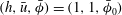 $(h,\bar{u},\bar{\unicode[STIX]{x1D719}})=(1,1,\bar{\unicode[STIX]{x1D719}}_{0})$
, and noting that
$(h,\bar{u},\bar{\unicode[STIX]{x1D719}})=(1,1,\bar{\unicode[STIX]{x1D719}}_{0})$
, and noting that
 $G_{0}^{\prime }<1$
, it can be seen that
$G_{0}^{\prime }<1$
, it can be seen that
 $\unicode[STIX]{x1D706}^{(1)}>0$
and
$\unicode[STIX]{x1D706}^{(1)}>0$
and
 $\unicode[STIX]{x1D706}^{(3)}>0$
. The other wavespeed
$\unicode[STIX]{x1D706}^{(3)}>0$
. The other wavespeed
 $\unicode[STIX]{x1D706}^{(2)}$
is positive for
$\unicode[STIX]{x1D706}^{(2)}$
is positive for
 $F>1$
and negative for
$F>1$
and negative for
 $F<1$
. Most importantly, at the critical Froude number
$F<1$
. Most importantly, at the critical Froude number
 $$\begin{eqnarray}\displaystyle F=F_{c}\equiv \frac{1}{|G_{0}^{\prime }|}, & & \displaystyle\end{eqnarray}$$
the large particle transport equation’s characteristic wavespeed (5.26) coincides with one of those from the shallow water equations (5.25), depending on the sign of
 $G_{0}^{\prime }$
, and the system loses strict hyperbolicity. This is the point at which unbounded growth rates are found in the linear stability analysis for the inviscid model. It is therefore vital to check that the growth rate for this new viscous model remains bounded for all wavenumbers by conducting an asymptotic analysis of the characteristic polynomial (5.22) for
$G_{0}^{\prime }$
, and the system loses strict hyperbolicity. This is the point at which unbounded growth rates are found in the linear stability analysis for the inviscid model. It is therefore vital to check that the growth rate for this new viscous model remains bounded for all wavenumbers by conducting an asymptotic analysis of the characteristic polynomial (5.22) for
 $k\gg 1$
. The reader is referred to appendix A for the full details, but a summary of the key results is given in the following sections.
$k\gg 1$
. The reader is referred to appendix A for the full details, but a summary of the key results is given in the following sections.
5.3 Inviscid high wavenumber asymptotics
For completeness, we begin by considering the inviscid case,
 $\unicode[STIX]{x1D708}=0$
. The real part of the three roots is found to behave like
$\unicode[STIX]{x1D708}=0$
. The real part of the three roots is found to behave like
 $$\begin{eqnarray}\displaystyle & \displaystyle \unicode[STIX]{x1D70E}_{R}^{(1)}\sim \frac{(FG_{0}^{\prime }-1)(F\unicode[STIX]{x1D707}_{h}-\unicode[STIX]{x1D707}_{\bar{u}})+FG_{0}(1-F)\unicode[STIX]{x1D707}_{\bar{\unicode[STIX]{x1D719}}}}{2F^{2}(FG_{0}^{\prime }-1)}, & \displaystyle\end{eqnarray}$$
 $$\begin{eqnarray}\displaystyle & \displaystyle \unicode[STIX]{x1D70E}_{R}^{(2)}\sim \frac{-(FG_{0}^{\prime }+1)(F\unicode[STIX]{x1D707}_{h}+\unicode[STIX]{x1D707}_{\bar{u}})+FG_{0}(1+F)\unicode[STIX]{x1D707}_{\bar{\unicode[STIX]{x1D719}}}}{2F^{2}(FG_{0}^{\prime }+1)}, & \displaystyle\end{eqnarray}$$
 $$\begin{eqnarray}\displaystyle & \displaystyle \unicode[STIX]{x1D70E}_{R}^{(3)}\sim \frac{G_{0}(1-G_{0}^{\prime })\unicode[STIX]{x1D707}_{\bar{\unicode[STIX]{x1D719}}}}{F^{2}(G_{0}^{\prime })^{2}-1}, & \displaystyle\end{eqnarray}$$
 $\unicode[STIX]{x1D70E}_{M}$
tends to a constant value as
$\unicode[STIX]{x1D70E}_{M}$
tends to a constant value as
 $k\longrightarrow \infty$
. From the definition (5.17) and the assumption (3.5) that large particles experience greater frictional forces, it follows that
$k\longrightarrow \infty$
. From the definition (5.17) and the assumption (3.5) that large particles experience greater frictional forces, it follows that
 $\unicode[STIX]{x1D707}_{\bar{\unicode[STIX]{x1D719}}}<0$
. Using this, and the fact that
$\unicode[STIX]{x1D707}_{\bar{\unicode[STIX]{x1D719}}}<0$
. Using this, and the fact that
 $G_{0}^{\prime }<1$
by (5.14), it can be seen that that
$G_{0}^{\prime }<1$
by (5.14), it can be seen that that
 $\unicode[STIX]{x1D70E}_{R}^{(3)}>0$
for
$\unicode[STIX]{x1D70E}_{R}^{(3)}>0$
for
 $F<F_{c}$
, where the critical Froude number is defined by (5.27). The growth rate
$F<F_{c}$
, where the critical Froude number is defined by (5.27). The growth rate
 $\unicode[STIX]{x1D70E}_{M}$
is therefore always positive for
$\unicode[STIX]{x1D70E}_{M}$
is therefore always positive for
 $F<F_{c}$
, meaning perturbations grow in time and the base state is unstable as
$F<F_{c}$
, meaning perturbations grow in time and the base state is unstable as
 $k\longrightarrow \infty$
(figure 9
a). For
$k\longrightarrow \infty$
(figure 9
a). For
 $F>F_{c}$
the third root
$F>F_{c}$
the third root
 $\unicode[STIX]{x1D70E}_{R}^{(3)}$
is now stable in the asymptotic limit and one must investigate the sign of the other roots
$\unicode[STIX]{x1D70E}_{R}^{(3)}$
is now stable in the asymptotic limit and one must investigate the sign of the other roots
 $\unicode[STIX]{x1D70E}_{R}^{(1)}$
and
$\unicode[STIX]{x1D70E}_{R}^{(1)}$
and
 $\unicode[STIX]{x1D70E}_{R}^{(2)}$
. For the parameters given in table 1 at least one of (5.28) or (5.29) is positive for all regions of
$\unicode[STIX]{x1D70E}_{R}^{(2)}$
. For the parameters given in table 1 at least one of (5.28) or (5.29) is positive for all regions of
 $(h_{0},\bar{\unicode[STIX]{x1D719}}_{0})$
space, meaning that
$(h_{0},\bar{\unicode[STIX]{x1D719}}_{0})$
space, meaning that
 $\unicode[STIX]{x1D70E}_{M}>0$
and the base state is again unstable (figure 9
b).
$\unicode[STIX]{x1D70E}_{M}>0$
and the base state is again unstable (figure 9
b).
At the critical Froude number
 $F=F_{c}$
the third root
$F=F_{c}$
the third root
 $\unicode[STIX]{x1D70E}_{R}^{(3)}$
and either
$\unicode[STIX]{x1D70E}_{R}^{(3)}$
and either
 $\unicode[STIX]{x1D70E}_{R}^{(1)}$
or
$\unicode[STIX]{x1D70E}_{R}^{(1)}$
or
 $\unicode[STIX]{x1D70E}_{R}^{(2)}$
become infinite, depending on the sign of
$\unicode[STIX]{x1D70E}_{R}^{(2)}$
become infinite, depending on the sign of
 $G_{0}^{\prime }$
. In these singular cases, the leading-order growth rate is instead given by the distinguished limit
$G_{0}^{\prime }$
. In these singular cases, the leading-order growth rate is instead given by the distinguished limit
 $$\begin{eqnarray}\displaystyle \unicode[STIX]{x1D70E}_{R}^{(\pm )}\sim \pm {\textstyle \frac{1}{2}}|G_{0}G_{0}^{\prime }(1-G_{0}^{\prime })\unicode[STIX]{x1D707}_{\bar{\unicode[STIX]{x1D719}}}|^{1/2}k^{1/2}, & & \displaystyle\end{eqnarray}$$
for large
 $k$
. The positive root in (5.31) will give unbounded growth rates proportional to
$k$
. The positive root in (5.31) will give unbounded growth rates proportional to
 $k^{1/2}$
(figure 10), which is the same as the one-dimensional result found in Woodhouse et al. (Reference Woodhouse, Thornton, Johnson, Kokelaar and Gray2012) and means that the inviscid model is ill posed in the sense of Joseph & Saut (Reference Joseph and Saut1990).
$k^{1/2}$
(figure 10), which is the same as the one-dimensional result found in Woodhouse et al. (Reference Woodhouse, Thornton, Johnson, Kokelaar and Gray2012) and means that the inviscid model is ill posed in the sense of Joseph & Saut (Reference Joseph and Saut1990).
5.4 Viscous high wavenumber asymptotics
Returning to the viscous equations (finite
 $R>0$
), the leading-order behaviour of the three roots are
$R>0$
), the leading-order behaviour of the three roots are
 $$\begin{eqnarray}\displaystyle & \displaystyle \unicode[STIX]{x1D70E}_{R}^{(1)}\sim -\frac{1}{R}k^{2}, & \displaystyle\end{eqnarray}$$
 $$\begin{eqnarray}\displaystyle & \displaystyle \unicode[STIX]{x1D70E}_{R}^{(2)}\sim -\frac{R}{F^{2}}, & \displaystyle\end{eqnarray}$$
 $$\begin{eqnarray}\displaystyle & \displaystyle \unicode[STIX]{x1D70E}_{R}^{(3)}\sim \frac{R^{2}G_{0}(1-G_{0}^{\prime })(F^{2}(G_{0}^{\prime })^{2}-1)\unicode[STIX]{x1D707}_{\bar{\unicode[STIX]{x1D719}}}}{F^{4}(G_{0}^{\prime })^{2}}\frac{1}{k^{2}}, & \displaystyle\end{eqnarray}$$
 $k\gg 1$
(see § A.2). In this high wavenumber limit, the first two of these are stable for all Froude numbers, whereas the third root is stable for
$k\gg 1$
(see § A.2). In this high wavenumber limit, the first two of these are stable for all Froude numbers, whereas the third root is stable for
 $F>F_{c}$
and unstable for
$F>F_{c}$
and unstable for
 $F<F_{c}$
. To see this, note that
$F<F_{c}$
. To see this, note that
 $G_{0}^{\prime }<1$
,
$G_{0}^{\prime }<1$
,
 $\unicode[STIX]{x1D707}_{\bar{\unicode[STIX]{x1D719}}}<0$
, and
$\unicode[STIX]{x1D707}_{\bar{\unicode[STIX]{x1D719}}}<0$
, and
 $F^{2}(G_{0}^{\prime })^{2}$
may be written as
$F^{2}(G_{0}^{\prime })^{2}$
may be written as
 $(F/F_{c})^{2}$
. Whilst the sign is consistent with the inviscid case (5.30), the third root (5.34) does not tend to a constant value as
$(F/F_{c})^{2}$
. Whilst the sign is consistent with the inviscid case (5.30), the third root (5.34) does not tend to a constant value as
 $k\longrightarrow \infty$
, and instead decays to zero like
$k\longrightarrow \infty$
, and instead decays to zero like
 $1/k^{2}$
(figure 9
a). This is significant because it means that the growth rate
$1/k^{2}$
(figure 9
a). This is significant because it means that the growth rate
 $\unicode[STIX]{x1D70E}_{M}(k)$
will take its maximum value
$\unicode[STIX]{x1D70E}_{M}(k)$
will take its maximum value
 $\unicode[STIX]{x1D70E}_{Max}=\max (\unicode[STIX]{x1D70E}_{M})$
at a finite wavenumber
$\unicode[STIX]{x1D70E}_{Max}=\max (\unicode[STIX]{x1D70E}_{M})$
at a finite wavenumber
 $k=k_{M}$
, corresponding to the most unstable mode. Furthermore, for finite values of
$k=k_{M}$
, corresponding to the most unstable mode. Furthermore, for finite values of
 $R>0$
the base state is always stable in the high wavenumber limit when
$R>0$
the base state is always stable in the high wavenumber limit when
 $F>F_{c}$
. This leads to a cutoff wavenumber
$F>F_{c}$
. This leads to a cutoff wavenumber
 $k=k_{c}$
, and all perturbations with
$k=k_{c}$
, and all perturbations with
 $k>k_{c}$
are stable (figures 9
b and 11
b). Neither of these features are present in the inviscid regime, where the maximum growth rates are given by the asymptotic limits (5.28), (5.29) or (5.30). It is possible to derive analytical expressions for the cutoff wavenumber
$k>k_{c}$
are stable (figures 9
b and 11
b). Neither of these features are present in the inviscid regime, where the maximum growth rates are given by the asymptotic limits (5.28), (5.29) or (5.30). It is possible to derive analytical expressions for the cutoff wavenumber
 $k_{c}$
, details of which are given in § A.3.
$k_{c}$
, details of which are given in § A.3.
(a) Plots of the maximum growth rate
 $\unicode[STIX]{x1D70E}_{Max}$
against steady-state Froude number
$\unicode[STIX]{x1D70E}_{Max}$
against steady-state Froude number
 $F$
. The inviscid values are infinite at
$F$
. The inviscid values are infinite at
 $F=F_{c}$
, whereas
$F=F_{c}$
, whereas
 $\unicode[STIX]{x1D70E}_{Max}$
remains bounded for all Froude numbers when viscosity is included. (b) The cutoff wavenumber
$\unicode[STIX]{x1D70E}_{Max}$
remains bounded for all Froude numbers when viscosity is included. (b) The cutoff wavenumber
 $k_{c}$
as a function of
$k_{c}$
as a function of
 $F$
, which only exists for the viscous regime, providing that
$F$
, which only exists for the viscous regime, providing that
 $F>F_{c}$
. Larger values of the coefficient
$F>F_{c}$
. Larger values of the coefficient
 $\unicode[STIX]{x1D708}$
lead to smaller
$\unicode[STIX]{x1D708}$
lead to smaller
 $\unicode[STIX]{x1D70E}_{Max}$
and
$\unicode[STIX]{x1D70E}_{Max}$
and
 $k_{c}$
. In both plots the depth-averaged concentration is fixed at
$k_{c}$
. In both plots the depth-averaged concentration is fixed at
 $\bar{\unicode[STIX]{x1D719}}_{0}=0.8$
and
$\bar{\unicode[STIX]{x1D719}}_{0}=0.8$
and
 $F$
is varied by changing the steady-state thickness
$F$
is varied by changing the steady-state thickness
 $h_{0}$
.
$h_{0}$
.
At the critical Froude number the expression (5.34) reduces to zero (since
 $F^{2}(G_{0}^{\prime })^{2}=1$
) and a new asymptotic analysis leads to
$F^{2}(G_{0}^{\prime })^{2}=1$
) and a new asymptotic analysis leads to
 $$\begin{eqnarray}\displaystyle \unicode[STIX]{x1D70E}_{R}^{(3)}\sim 2R^{3}G_{0}^{2}(G_{0}^{\prime })^{2}(1-G_{0}^{\prime })^{2}\unicode[STIX]{x1D707}_{\bar{\unicode[STIX]{x1D719}}}^{2}\frac{1}{k^{4}}, & & \displaystyle\end{eqnarray}$$
in the high wavenumber limit. The expression (5.35) is strictly positive, meaning the root is unstable for
 $k\gg 1$
. Intuitively, this result agrees with the inviscid analysis for the critical regime, since these are in some sense the most unstable cases. However, the growth rate crucially remains bounded for all values of
$k\gg 1$
. Intuitively, this result agrees with the inviscid analysis for the critical regime, since these are in some sense the most unstable cases. However, the growth rate crucially remains bounded for all values of
 $k$
when viscous terms are included, and in fact decays like
$k$
when viscous terms are included, and in fact decays like
 $1/k^{4}$
as
$1/k^{4}$
as
 $k\longrightarrow \infty$
(figure 10). This ensures that the model is well-posed, even in the previously problematic critical regime. These important results are highlighted in figure 11(a), which shows the maximum growth rates
$k\longrightarrow \infty$
(figure 10). This ensures that the model is well-posed, even in the previously problematic critical regime. These important results are highlighted in figure 11(a), which shows the maximum growth rates
 $\unicode[STIX]{x1D70E}_{Max}$
as a function of steady uniform Froude number
$\unicode[STIX]{x1D70E}_{Max}$
as a function of steady uniform Froude number
 $F$
. For the inviscid equations
$F$
. For the inviscid equations
 $\unicode[STIX]{x1D70E}_{Max}\longrightarrow \infty$
as
$\unicode[STIX]{x1D70E}_{Max}\longrightarrow \infty$
as
 $F\longrightarrow F_{c}$
, whereas the viscous curves remain bounded for all Froude numbers.
$F\longrightarrow F_{c}$
, whereas the viscous curves remain bounded for all Froude numbers.
As already noted, the linear stability calculations shown on figures 9 and 10 are computed using a fixed coefficient in the effective viscosity
 $\unicode[STIX]{x1D708}=0.001~\text{m}^{3/2}~\text{s}^{-1}$
, and qualitatively similar behaviour is found for all positive choices of
$\unicode[STIX]{x1D708}=0.001~\text{m}^{3/2}~\text{s}^{-1}$
, and qualitatively similar behaviour is found for all positive choices of
 $\unicode[STIX]{x1D708}$
. The specific value does not affect whether the equations are well posed, but it does have an influence on the stability of steady uniform flows. Increasing
$\unicode[STIX]{x1D708}$
. The specific value does not affect whether the equations are well posed, but it does have an influence on the stability of steady uniform flows. Increasing
 $\unicode[STIX]{x1D708}$
, and consequently reducing the Reynolds number
$\unicode[STIX]{x1D708}$
, and consequently reducing the Reynolds number
 $R$
, leads to lower maximum growth rates
$R$
, leads to lower maximum growth rates
 $\unicode[STIX]{x1D70E}_{Max}$
(figure 11
a) and therefore has a stabilising effect on the base state. The most unstable mode
$\unicode[STIX]{x1D70E}_{Max}$
(figure 11
a) and therefore has a stabilising effect on the base state. The most unstable mode
 $k_{M}$
and cutoff wavenumber
$k_{M}$
and cutoff wavenumber
 $k_{c}$
(when it exists) decrease with increasing
$k_{c}$
(when it exists) decrease with increasing
 $\unicode[STIX]{x1D708}$
(figure 11
b).
$\unicode[STIX]{x1D708}$
(figure 11
b).
6 Two-dimensional numerical simulations for a propagating front
Having eliminated the possibility of unbounded growth rates as a source of ill posedness, the capability of the new governing equations to model physical systems may be tested. One such system is segregation-induced fingering instabilities that develop as a front of bidisperse material propagates down an inclined plane (see figures 2, 3, movie 1 and Pouliquen et al. Reference Pouliquen, Delour and Savage1997; Pouliquen & Vallance Reference Pouliquen and Vallance1999; Woodhouse et al. Reference Woodhouse, Thornton, Johnson, Kokelaar and Gray2012, for example). In an initially homogeneous mixture large particles are rapidly segregated to the surface, where the higher velocity shears them to the front. Here they are overrun, resegregated upwards and recirculated by the bulk to form a coarse-rich flow head. This head experiences enhanced frictional forces and may break down into a series of ‘finger-like’ structures. Each finger is bounded by static or slowly moving levees of coarse material that channelise the finer, more mobile interior. This phenomenon is important because it is an example of a segregation-mobility feedback effect, with the instability being suppressed in experiments using monodisperse material (see figure 5). Woodhouse et al. (Reference Woodhouse, Thornton, Johnson, Kokelaar and Gray2012) were able to produce numerical simulations showing spontaneous leveed finger formation and elongation, but their results were grid dependent due to the ill posedness discussed in the previous sections.
6.1 Generalised equations
Many granular flow configurations have little variation in the lateral direction, allowing them to be modelled by one-dimensional (depth-averaged) equations governing the evolution in time and downslope direction (e.g. Gray & Edwards Reference Gray and Edwards2014; Edwards & Gray Reference Edwards and Gray2015). However, the instability that occurs as a bidisperse mixture propagates down a plane is predominantly in the transverse direction, meaning that the lateral dependence needs to be explicitly accounted for in the model. The governing equations must therefore be extended to two spatial dimensions. Baker et al. (Reference Baker, Barker and Gray2016) examined a similar problem for monodisperse material and generalised the one-dimensional depth-averaged
 $\unicode[STIX]{x1D707}(I)$
-rheology of Gray & Edwards (Reference Gray and Edwards2014) to two dimensions. Using their work as a base and introducing a cross-slope coordinate
$\unicode[STIX]{x1D707}(I)$
-rheology of Gray & Edwards (Reference Gray and Edwards2014) to two dimensions. Using their work as a base and introducing a cross-slope coordinate
 $y$
and depth-averaged velocity
$y$
and depth-averaged velocity
 $\bar{v}$
, the two-dimensional segregation-mobility feedback equations (reverting to dimensional variables) are
$\bar{v}$
, the two-dimensional segregation-mobility feedback equations (reverting to dimensional variables) are
 $$\begin{eqnarray}\displaystyle & \displaystyle \frac{\unicode[STIX]{x2202}h}{\unicode[STIX]{x2202}t}+\unicode[STIX]{x1D735}\boldsymbol{\cdot }(h\bar{\boldsymbol{u}})=0, & \displaystyle\end{eqnarray}$$
 $$\begin{eqnarray}\displaystyle & \displaystyle \frac{\unicode[STIX]{x2202}}{\unicode[STIX]{x2202}t}(h\bar{\boldsymbol{u}})+\unicode[STIX]{x1D735}\boldsymbol{\cdot }(h\bar{\boldsymbol{u}}\otimes \bar{\boldsymbol{u}})+\unicode[STIX]{x1D735}\left(\frac{1}{2}gh^{2}\cos \unicode[STIX]{x1D701}\right)=gh\boldsymbol{S}+\unicode[STIX]{x1D735}\boldsymbol{\cdot }(\unicode[STIX]{x1D708}h^{3/2}\bar{\unicode[STIX]{x1D63F}}), & \displaystyle\end{eqnarray}$$
 $$\begin{eqnarray}\displaystyle & \displaystyle \frac{\unicode[STIX]{x2202}}{\unicode[STIX]{x2202}t}(h\bar{\unicode[STIX]{x1D719}})+\unicode[STIX]{x1D735}\boldsymbol{\cdot }(h\bar{\boldsymbol{u}}\bar{\unicode[STIX]{x1D719}})-\unicode[STIX]{x1D735}\boldsymbol{\cdot }(h\bar{\boldsymbol{u}}G(\bar{\unicode[STIX]{x1D719}}))=0, & \displaystyle\end{eqnarray}$$
 $\bar{\boldsymbol{u}}=(\bar{u},\bar{v})$
is the depth-averaged velocity vector,
$\bar{\boldsymbol{u}}=(\bar{u},\bar{v})$
is the depth-averaged velocity vector,
 $\unicode[STIX]{x1D735}=(\unicode[STIX]{x2202}/\unicode[STIX]{x2202}x,\unicode[STIX]{x2202}/\unicode[STIX]{x2202}y)$
denotes the gradient operator in
$\unicode[STIX]{x1D735}=(\unicode[STIX]{x2202}/\unicode[STIX]{x2202}x,\unicode[STIX]{x2202}/\unicode[STIX]{x2202}y)$
denotes the gradient operator in
 $(x,y)$
space, ‘
$(x,y)$
space, ‘
 $\boldsymbol{\cdot }$
’ is the dot product and
$\boldsymbol{\cdot }$
’ is the dot product and
 $\otimes$
the dyadic product. Assuming no basal topography, the source terms
$\otimes$
the dyadic product. Assuming no basal topography, the source terms
 $\boldsymbol{S}=(S_{x},S_{y})$
are given by
$\boldsymbol{S}=(S_{x},S_{y})$
are given by  $$\begin{eqnarray}\displaystyle S_{x}=\cos \unicode[STIX]{x1D701}\left(\tan \unicode[STIX]{x1D701}-\unicode[STIX]{x1D707}_{b}\frac{\bar{u}}{|\bar{\boldsymbol{u}}|}\right),\quad S_{y}=-\cos \unicode[STIX]{x1D701}\left(\unicode[STIX]{x1D707}_{b}\frac{\bar{v}}{|\bar{\boldsymbol{u}}|}\right), & & \displaystyle\end{eqnarray}$$
where
 $|\bar{\boldsymbol{u}}|=(\bar{u}^{2}+\bar{v}^{2})^{1/2}$
is the magnitude of the velocity. The basal friction law
$|\bar{\boldsymbol{u}}|=(\bar{u}^{2}+\bar{v}^{2})^{1/2}$
is the magnitude of the velocity. The basal friction law
 $\unicode[STIX]{x1D707}_{b}(h,Fr,\bar{\unicode[STIX]{x1D719}})$
is defined by (3.4) and (3.7) using the more general Froude number definition
$\unicode[STIX]{x1D707}_{b}(h,Fr,\bar{\unicode[STIX]{x1D719}})$
is defined by (3.4) and (3.7) using the more general Froude number definition
 $$\begin{eqnarray}\displaystyle Fr=\frac{|\bar{\boldsymbol{u}}|}{\sqrt{gh\cos \unicode[STIX]{x1D701}}}. & & \displaystyle\end{eqnarray}$$
The coefficient
 $\unicode[STIX]{x1D708}>0$
remains a free parameter for slope angles in the range (3.10), and the depth-integrated strain-rate tensor is
$\unicode[STIX]{x1D708}>0$
remains a free parameter for slope angles in the range (3.10), and the depth-integrated strain-rate tensor is
 $$\begin{eqnarray}\displaystyle \bar{\unicode[STIX]{x1D63F}}={\textstyle \frac{1}{2}}(\unicode[STIX]{x1D735}\bar{\boldsymbol{u}}+(\unicode[STIX]{x1D735}\bar{\boldsymbol{u}})^{\text{T}}). & & \displaystyle\end{eqnarray}$$
The generalised large particle transport equation (6.3) can be derived in a similar manner to the one-dimensional case (2.15), providing assumptions are made about the vertical variation of the transverse velocity. Whilst the downslope velocity magnitudes are typically much larger than their lateral counterparts, the thinness of the flow means that material responds to shear comparably in both directions, and thus the shear profile is taken to be the same (see Woodhouse et al.
Reference Woodhouse, Thornton, Johnson, Kokelaar and Gray2012). The transport function
 $G$
then remains unchanged and is given by (2.17) with
$G$
then remains unchanged and is given by (2.17) with
 $\unicode[STIX]{x1D6FC}=1/7$
.
$\unicode[STIX]{x1D6FC}=1/7$
.
Note that, for simplicity, the linear stability analysis conducted in § 5 is for the one-dimensional equations and does not strictly apply to their generalised form (6.1)–(6.3). One cannot guarantee that these will also be well posed without further calculations. Woodhouse et al. (Reference Woodhouse, Thornton, Johnson, Kokelaar and Gray2012) carried out a full two-dimensional stability analysis for their inviscid equations and found that the most unstable mode was usually in the downslope direction. In particular, the unbounded growth rates were only apparent in the large
 $k_{x}$
(downslope wavenumber) limit. The equivalent analysis has been carried out for the viscous equations (see appendix B), and unstable modes are only found for non-zero downslope perturbations. In all cases, the growth rates remain bounded for all wavenumbers, meaning the generalised equations are well posed.
$k_{x}$
(downslope wavenumber) limit. The equivalent analysis has been carried out for the viscous equations (see appendix B), and unstable modes are only found for non-zero downslope perturbations. In all cases, the growth rates remain bounded for all wavenumbers, meaning the generalised equations are well posed.
6.2 Numerical solutions
The system of coupled partial differential equations (PDEs) (6.1)–(6.3) is now solved numerically using the shock-capturing central scheme of Kurganov & Tadmor (Reference Kurganov and Tadmor2000). This is second order in space and has a semi-discrete formulation, allowing it to be combined with a time stepper of choice. In this case a Runge–Kutta–Chebyshev adaptive step method (Medovikov Reference Medovikov1998) is employed. The scheme is well suited to this particular problem because it is easily generalised to multiple spatial dimensions and is capable of handling convection–diffusion equations. It has previously been used to solve similar systems governing granular flows, for example a two-dimensional breaking size-segregation wave (Johnson et al.
Reference Johnson, Kokelaar, Iverson, Logan, LaHusen and Gray2012), granular roll waves (Gray & Edwards Reference Gray and Edwards2014; Razis et al.
Reference Razis, Edwards, Gray and van der Weele2014) and erosion–deposition waves (Edwards & Gray Reference Edwards and Gray2015). To calculate the numerical fluxes, the scheme requires the specification of a flux limiter. Here, the weighted essentially non-oscillatory (WENO) limiter detailed in Noelle (Reference Noelle2000) is chosen. In order to utilise the numerical method of Kurganov & Tadmor (Reference Kurganov and Tadmor2000), the governing equations must be written in conservative form. This introduces numerical singularities in both the convective and diffusive fluxes as
 $h\longrightarrow 0$
. To get around this potential problem a minimum flow thickness smaller than one particle diameter,
$h\longrightarrow 0$
. To get around this potential problem a minimum flow thickness smaller than one particle diameter,
 $h_{min}=10^{-4}~\text{m}$
, is introduced and the fluxes are set to zero whenever
$h_{min}=10^{-4}~\text{m}$
, is introduced and the fluxes are set to zero whenever
 $h<h_{min}$
.
$h<h_{min}$
.
For numerical simulations of a front of granular material advancing down an inclined plane, initial conditions of an empty slope
 $$\begin{eqnarray}\displaystyle h(x,y,0)=0,\quad \bar{u}(x,y,0)=0,\quad \bar{v}(x,y,0)=0,\quad \bar{\unicode[STIX]{x1D719}}(x,y,0)=0, & & \displaystyle\end{eqnarray}$$
are prescribed. Simulations are carried out on a computational domain
 $L_{x}\times L_{y}$
discretized over
$L_{x}\times L_{y}$
discretized over
 $N_{x}\times N_{y}$
grid cells, giving a spatial resolution of
$N_{x}\times N_{y}$
grid cells, giving a spatial resolution of
 $N_{x}/L_{x}\times N_{y}/L_{y}$
points per metre. Periodic boundary conditions are specified in the
$N_{x}/L_{x}\times N_{y}/L_{y}$
points per metre. Periodic boundary conditions are specified in the
 $y$
direction, and at the upstream boundary
$y$
direction, and at the upstream boundary
 $(x=0)$
the inflow conditions
$(x=0)$
the inflow conditions
 $$\begin{eqnarray}\displaystyle h(0,y,t)=(1-\text{e}^{-10t})h_{0},\quad \bar{u}(0,y,t)=\bar{u}_{0},\quad \bar{v}(0,y,t)=0,\quad \bar{\unicode[STIX]{x1D719}}(0,y,t)=\bar{\unicode[STIX]{x1D719}}_{0}+\unicode[STIX]{x1D6FF}\bar{\unicode[STIX]{x1D719}}_{p}(y), & & \displaystyle \nonumber\\ \displaystyle & & \displaystyle\end{eqnarray}$$
are enforced. These correspond to the steady uniform flow of § 4, with the thickness prefactor
 $(1-\text{e}^{-10t})$
used to ensure a smooth transition from an empty slope. Note that the simulations represent a continuous inflow (akin to figures 3
a, 4
a) as opposed to a finite release of material (figures 3
b, 4
b). To introduce transverse variation into the system the inflow concentration is perturbed with a periodic function
$(1-\text{e}^{-10t})$
used to ensure a smooth transition from an empty slope. Note that the simulations represent a continuous inflow (akin to figures 3
a, 4
a) as opposed to a finite release of material (figures 3
b, 4
b). To introduce transverse variation into the system the inflow concentration is perturbed with a periodic function
 $$\begin{eqnarray}\displaystyle \bar{\unicode[STIX]{x1D719}}_{p}(y)=\sin (2\unicode[STIX]{x03C0}y/L_{y}), & & \displaystyle\end{eqnarray}$$
of magnitude
 $\unicode[STIX]{x1D6FF}=8\times 10^{-5}$
. Simulations are halted before material reaches the downstream boundary and so, since the equations degenerate when
$\unicode[STIX]{x1D6FF}=8\times 10^{-5}$
. Simulations are halted before material reaches the downstream boundary and so, since the equations degenerate when
 $h=0$
, no boundary conditions are required at this end of the domain.
$h=0$
, no boundary conditions are required at this end of the domain.
Numerical solutions of the system of PDEs (6.1)–(6.3) showing the depth averaged concentration
 $\bar{\unicode[STIX]{x1D719}}$
at times
$\bar{\unicode[STIX]{x1D719}}$
at times
 $t=1.9~\text{s}$
(non-dimensional
$t=1.9~\text{s}$
(non-dimensional
 $\hat{t}=198$
),
$\hat{t}=198$
),
 $t=3.3~\text{s}$
(
$t=3.3~\text{s}$
(
 $\hat{t}=343$
),
$\hat{t}=343$
),
 $t=5.1~\text{s}$
(
$t=5.1~\text{s}$
(
 $\hat{t}=530$
),
$\hat{t}=530$
),
 $t=6.2~\text{s}$
(
$t=6.2~\text{s}$
(
 $\hat{t}=645$
) and
$\hat{t}=645$
) and
 $t=7.5~\text{s}$
(
$t=7.5~\text{s}$
(
 $\hat{t}=780$
). A large-rich region quickly develops at the flow front
$\hat{t}=780$
). A large-rich region quickly develops at the flow front
 $(t=1.9~\text{s})$
, starts to become unstable
$(t=1.9~\text{s})$
, starts to become unstable
 $(t=5.1~\text{s})$
and develops into fingers
$(t=5.1~\text{s})$
and develops into fingers
 $(t=6.2~\text{s})$
which elongate and coarsen over time. It is clear that lateral levees bounding the fingers consist predominantly of large particles. The colour scheme has been chosen to mimic experiments, with turquoise representing the region where the chute is empty,
$(t=6.2~\text{s})$
which elongate and coarsen over time. It is clear that lateral levees bounding the fingers consist predominantly of large particles. The colour scheme has been chosen to mimic experiments, with turquoise representing the region where the chute is empty,
 $h<h_{min}$
. Parameters are
$h<h_{min}$
. Parameters are
 $h_{0}=2~\text{mm}$
,
$h_{0}=2~\text{mm}$
,
 $\bar{\unicode[STIX]{x1D719}}_{0}=0.8$
,
$\bar{\unicode[STIX]{x1D719}}_{0}=0.8$
,
 $\bar{u}_{0}=0.208~\text{ms}^{-1}$
,
$\bar{u}_{0}=0.208~\text{ms}^{-1}$
,
 $F=1.57$
,
$F=1.57$
,
 $\unicode[STIX]{x1D708}=0.01~\text{m}^{3/2}~\text{s}^{-1}$
,
$\unicode[STIX]{x1D708}=0.01~\text{m}^{3/2}~\text{s}^{-1}$
,
 $N_{x}/L_{x}=N_{y}/L_{y}=750~\text{m}^{-1}$
. Note that the axes limits
$N_{x}/L_{x}=N_{y}/L_{y}=750~\text{m}^{-1}$
. Note that the axes limits
 $L_{x}=1.5~\text{m}$
,
$L_{x}=1.5~\text{m}$
,
 $L_{y}=0.5~\text{m}$
correspond to non-dimensional values of
$L_{y}=0.5~\text{m}$
correspond to non-dimensional values of
 $\hat{L}_{x}=750$
and
$\hat{L}_{x}=750$
and
 $\hat{L}_{y}=250$
respectively. Supplementary movie 3 available online.
$\hat{L}_{y}=250$
respectively. Supplementary movie 3 available online.

Numerical solutions of the system of PDEs (6.1)–(6.3) showing the speed
 $|\bar{\boldsymbol{u}}|=(\bar{u}^{2}+\bar{v}^{2})^{1/2}$
at times
$|\bar{\boldsymbol{u}}|=(\bar{u}^{2}+\bar{v}^{2})^{1/2}$
at times
 $t=1.9~\text{s}$
,
$t=1.9~\text{s}$
,
 $t=3.3~\text{s}$
,
$t=3.3~\text{s}$
,
 $t=5.1~\text{s}$
,
$t=5.1~\text{s}$
,
 $t=6.2~\text{s}$
and
$t=6.2~\text{s}$
and
 $t=7.5~\text{s}$
. Once the flow breaks up into fingers the lateral levees are close to stationary, with areas of much faster flow down the central, channelised regions representing the more mobile interior. Parameters are the same as in figure 12, meaning that a dimensional velocity of
$t=7.5~\text{s}$
. Once the flow breaks up into fingers the lateral levees are close to stationary, with areas of much faster flow down the central, channelised regions representing the more mobile interior. Parameters are the same as in figure 12, meaning that a dimensional velocity of
 $|\bar{\boldsymbol{u}}|=0.208~\text{m}~\text{s}^{-1}$
would correspond to a non-dimensional value of
$|\bar{\boldsymbol{u}}|=0.208~\text{m}~\text{s}^{-1}$
would correspond to a non-dimensional value of
 $|\hat{\bar{\boldsymbol{u}}}|=1$
. Supplementary movie 3 available online.
$|\hat{\bar{\boldsymbol{u}}}|=1$
. Supplementary movie 3 available online.

Numerical solutions of the system of PDEs (6.1)–(6.3) showing the flow thickness
 $h$
. Simulations are shown at times
$h$
. Simulations are shown at times
 $t=1.9$
s,
$t=1.9$
s,
 $t=3.3$
s,
$t=3.3$
s,
 $t=5.1~\text{s}$
,
$t=5.1~\text{s}$
,
 $t=6.2~\text{s}$
and
$t=6.2~\text{s}$
and
 $t=7.5~\text{s}$
. The propagating front breaks up into a series of fingers going to zero thickness at the boundaries. A region of thicker flow follows behind the main front. Parameters used are the same as figures 12 and 13, meaning a dimensional thickness of
$t=7.5~\text{s}$
. The propagating front breaks up into a series of fingers going to zero thickness at the boundaries. A region of thicker flow follows behind the main front. Parameters used are the same as figures 12 and 13, meaning a dimensional thickness of
 $h=2~\text{mm}$
represents
$h=2~\text{mm}$
represents
 ${\hat{h}}=1$
in non-dimensional terms. Supplementary movie 3 available online.
${\hat{h}}=1$
in non-dimensional terms. Supplementary movie 3 available online.

Figures 12–14 and supplementary movie 3 show the resulting contours of the flow height
 $h$
, depth-averaged concentration
$h$
, depth-averaged concentration
 $\bar{\unicode[STIX]{x1D719}}$
and speed
$\bar{\unicode[STIX]{x1D719}}$
and speed
 $|\bar{\boldsymbol{u}}|$
. It can be seen that the governing equations are able to qualitatively reproduce many of the key phenomena present in the experimental set-up. The concentration plots (figure 12) show that a large-particle-rich front quickly develops and subsequently breaks up into a series of fingers. These are bounded by coarse-grained lateral levees, and elongate as time progresses. As the fingers emerge from the uniform front the large particles are shouldered aside into slow moving coarse-particle-rich levees, and the large particle regions at the finger tips are dramatically reduced in size. In practice a breaking size-segregation wave will form just behind the front (Thornton & Gray Reference Thornton and Gray2008; Gray & Ancey Reference Gray and Ancey2009; Johnson et al.
Reference Johnson, Kokelaar, Iverson, Logan, LaHusen and Gray2012; Gajjar et al.
Reference Gajjar, van der Vaart, Thornton, Johnson, Ancey and Gray2016) which in the depth-averaged segregation theory (Gray & Kokelaar Reference Gray and Kokelaar2010a
,Reference Gray and Kokelaar
b
) is replaced by a depth-averaged concentration shock. The existence of a breaking size-segregation wave in the physical experiments, as well as diffusion, makes the transition at the large-rich front much more diffuse than predicted in the simulations.
$|\bar{\boldsymbol{u}}|$
. It can be seen that the governing equations are able to qualitatively reproduce many of the key phenomena present in the experimental set-up. The concentration plots (figure 12) show that a large-particle-rich front quickly develops and subsequently breaks up into a series of fingers. These are bounded by coarse-grained lateral levees, and elongate as time progresses. As the fingers emerge from the uniform front the large particles are shouldered aside into slow moving coarse-particle-rich levees, and the large particle regions at the finger tips are dramatically reduced in size. In practice a breaking size-segregation wave will form just behind the front (Thornton & Gray Reference Thornton and Gray2008; Gray & Ancey Reference Gray and Ancey2009; Johnson et al.
Reference Johnson, Kokelaar, Iverson, Logan, LaHusen and Gray2012; Gajjar et al.
Reference Gajjar, van der Vaart, Thornton, Johnson, Ancey and Gray2016) which in the depth-averaged segregation theory (Gray & Kokelaar Reference Gray and Kokelaar2010a
,Reference Gray and Kokelaar
b
) is replaced by a depth-averaged concentration shock. The existence of a breaking size-segregation wave in the physical experiments, as well as diffusion, makes the transition at the large-rich front much more diffuse than predicted in the simulations.
Note that the coarse-rich front that forms before the onset of finger formation is not a steady travelling wave solution to the system of equations, because large particles continue to accrue at the flow front (Gray & Kokelaar Reference Gray and Kokelaar2010a
). A steadily travelling base state must include a mechanism to counteract this accumulation, which Gray & Ancey (Reference Gray and Ancey2009) achieved by depositing the coarser grains arriving at the front onto the underlying substrate. In the absence of basal deposition the large particles may be removed from the frontal region through lateral advection towards the levees, and Johnson et al. (Reference Johnson, Kokelaar, Iverson, Logan, LaHusen and Gray2012) showed that this gave rise to a steady travelling segregation profile on the flow centreline, for a specified flow thickness and velocity field. We now believe that a single leveed finger can propagate steadily downslope, and anticipate that such a travelling wave solution to equations (6.1)–(6.3) would be an appropriate base state, although this has not been confirmed. This behaviour is in direct contrast to the pure small limit (
 $\bar{\unicode[STIX]{x1D719}}=1$
). Assuming no transverse variation, the monodisperse equations admit a steady travelling front solution (Gray & Edwards Reference Gray and Edwards2014), which can be found analytically (Gray & Ancey Reference Gray and Ancey2009) or numerically (Pouliquen Reference Pouliquen1999b
) and is unaffected by the new viscous terms. Two-dimensional computations suggest that this base state does not break down into fingers, which is consistent with the monodisperse experiments (figure 5), although roll waves may form and travel to the flow front.
$\bar{\unicode[STIX]{x1D719}}=1$
). Assuming no transverse variation, the monodisperse equations admit a steady travelling front solution (Gray & Edwards Reference Gray and Edwards2014), which can be found analytically (Gray & Ancey Reference Gray and Ancey2009) or numerically (Pouliquen Reference Pouliquen1999b
) and is unaffected by the new viscous terms. Two-dimensional computations suggest that this base state does not break down into fingers, which is consistent with the monodisperse experiments (figure 5), although roll waves may form and travel to the flow front.
From figure 13 it can be seen that once the fingers form the material travelling down the centre of the channels is moving approximately twice as fast as the steady uniform flow behind. This can be explained by examining the coarse-rich lateral levees, where the flow approaches zero velocity at the margins between adjacent fingers. To account for these reduced flux sections, the central regions must increase their flux, through a combination of flow thickening and increased speed, in order to conserve material from the constant inflow. There is an important discrepancy in the slow moving zones between experiments and numerics. In the laboratory, some of the material in the levees is completely stationary, but this is not achieved at any point in the simulations. Whilst this is not a major problem for the fingers that form from a continuous source (figures 3 a, 4 a), as the inflow is cutoff and the flow wanes the static regions become more significant and lead to distinct fingers separated by grain-free regions (figures 3 b, 4 b). In order to bring material to rest and prevent merging and coarsening of fingers in the final stages of flow, the extended friction law of Pouliquen & Forterre (Reference Pouliquen and Forterre2002) needs to be generalised to bidisperse material and implemented.
The flow thickness plots (figure 14) show that the region immediately behind the flow front is elevated above the steady uniform inflow depth. This is consistent with observations of bulbous flow fronts in both experiments and geophysical events (Johnson et al. Reference Johnson, Kokelaar, Iverson, Logan, LaHusen and Gray2012; Kokelaar et al. Reference Kokelaar, Graham, Gray and Vallance2014). There are also regions at the rear of the fingers that are significantly higher than the rest of the material. Comparing with figures 12 and 13, these correspond to the large particle islands that are also seen in small-scale experiments. For the continuous inflow regime simulated here, they move slowly downstream, which matches the experimental erosion processes (figure 3 a). Whilst there are no quantitative comparisons made at this stage, typical time scales for the onset of finger formation are roughly consistent. The channel widths do not correspond to the imposed inflow perturbation, meaning they are set by the system itself, and are of the correct order of magnitude (around 5 cm for the simulations shown). Further discussion about the finger characteristics follows in the next section.
Numerical simulations of depth-averaged concentration
 $\bar{\unicode[STIX]{x1D719}}$
at time
$\bar{\unicode[STIX]{x1D719}}$
at time
 $t=7.5~\text{s}$
for different grid resolutions and domain widths
$t=7.5~\text{s}$
for different grid resolutions and domain widths
 $L_{y}$
. Black dotted lines denote the maximum and minimum front position, as defined by (6.10) and (6.11) respectively. The final results are not identical, but the width and downslope extent of the fingers is similar for all runs. Other parameters used are the same as in figures 12–14.
$L_{y}$
. Black dotted lines denote the maximum and minimum front position, as defined by (6.10) and (6.11) respectively. The final results are not identical, but the width and downslope extent of the fingers is similar for all runs. Other parameters used are the same as in figures 12–14.

6.3 Finger characteristics: numerical versus physical viscosity
As well as showing that the new equations remove the possibility of unbounded growth rates, it also needs to be checked that the resulting simulations are grid convergent. Both the experiments and the non-linear equations exhibit high sensitivity to the initial conditions, which is highlighted numerically by the apparent random nature of the resulting fingers. Even though these arise through the integration of deterministic PDEs, numerical round-off error, subsequently magnified by the underlying instability of the equations, is sufficient to break the symmetry of the inflow (6.8) and (6.9). Changing the grid resolution will change these conditions, and one can therefore not expect to obtain identical results when running simulations with different numbers of grid points. Attention is instead given to the wavelength of fingers (cross-slope distance between two adjacent channels) and their elongation (downslope distance between front and rear of leveed region). Woodhouse et al. (Reference Woodhouse, Thornton, Johnson, Kokelaar and Gray2012) showed that, for the inviscid equations, the wavelength got progressively smaller and the fingers more elongated with decreasing mesh size, suggesting that numerical viscosity was a controlling factor for channel characteristics.
Computations are carried out for different grid resolutions and domain widths
 $L_{y}$
, and example results are shown on figure 15. The depth-averaged concentration
$L_{y}$
, and example results are shown on figure 15. The depth-averaged concentration
 $\bar{\unicode[STIX]{x1D719}}$
is plotted at time
$\bar{\unicode[STIX]{x1D719}}$
is plotted at time
 $t=7.5~\text{s}$
. As expected, the results are not perfectly identical for varying numbers of grid points, with the position and shape of the fingers changing slightly between runs. This is actually a desirable property, since no two experiments are identical and so it is good that the numerics exhibit a similar degree of sensitivity. However, like the experiments, the numerical finger width and their elongation stays approximately the same, which is in direct contrast to Woodhouse et al. (Reference Woodhouse, Thornton, Johnson, Kokelaar and Gray2012). At a given time it is straightforward to calculate the mean finger wavelength
$t=7.5~\text{s}$
. As expected, the results are not perfectly identical for varying numbers of grid points, with the position and shape of the fingers changing slightly between runs. This is actually a desirable property, since no two experiments are identical and so it is good that the numerics exhibit a similar degree of sensitivity. However, like the experiments, the numerical finger width and their elongation stays approximately the same, which is in direct contrast to Woodhouse et al. (Reference Woodhouse, Thornton, Johnson, Kokelaar and Gray2012). At a given time it is straightforward to calculate the mean finger wavelength
 $\unicode[STIX]{x1D6EC}$
by dividing the domain width
$\unicode[STIX]{x1D6EC}$
by dividing the domain width
 $L_{y}$
by the number of fingers, and this is shown on figure 16(a) for the different computations. There is some variation when too few cells are used, but the wavelength converges at sufficiently high resolutions and is independent of the domain width. Note that counting the number of fingers from plots such as figure 15 is fairly intuitive since the individual channels are well defined at this time,
$L_{y}$
by the number of fingers, and this is shown on figure 16(a) for the different computations. There is some variation when too few cells are used, but the wavelength converges at sufficiently high resolutions and is independent of the domain width. Note that counting the number of fingers from plots such as figure 15 is fairly intuitive since the individual channels are well defined at this time,
 $t=7.5~\text{s}$
. However, running the simulations for longer can lead to merging events, making precise definitions more difficult and meaning that
$t=7.5~\text{s}$
. However, running the simulations for longer can lead to merging events, making precise definitions more difficult and meaning that
 $\unicode[STIX]{x1D6EC}$
will also evolve over time.
$\unicode[STIX]{x1D6EC}$
will also evolve over time.
The effect of changing the grid resolution on (a) the mean finger wavelength
 $\unicode[STIX]{x1D6EC}$
at time
$\unicode[STIX]{x1D6EC}$
at time
 $t=7.5~\text{s}$
and (b) the front elongation
$t=7.5~\text{s}$
and (b) the front elongation
 $x_{l}$
(given by (6.10)–(6.12)) at times
$x_{l}$
(given by (6.10)–(6.12)) at times
 $t=2.5~\text{s}$
,
$t=2.5~\text{s}$
,
 $t=5.0~\text{s}$
and
$t=5.0~\text{s}$
and
 $t=7.5~\text{s}$
. Both tend to roughly constant values for large enough numbers of grid points.
$t=7.5~\text{s}$
. Both tend to roughly constant values for large enough numbers of grid points.

To estimate the elongation of the fingers, a maximum and minimum front position,
 $x_{f}^{+}$
and
$x_{f}^{+}$
and
 $x_{f}^{-}$
respectively, are defined for each time as
$x_{f}^{-}$
respectively, are defined for each time as
 $$\begin{eqnarray}\displaystyle & \displaystyle x_{f}^{+}(t)=\max \{x:h(x,y,t)<h_{min}\}, & \displaystyle\end{eqnarray}$$
 $$\begin{eqnarray}\displaystyle & \displaystyle x_{f}^{-}(t)=\min \{x:|\bar{\unicode[STIX]{x1D719}}(x,y,t)-\bar{\unicode[STIX]{x1D719}}_{0}|>\bar{\unicode[STIX]{x1D719}}_{0}/2\}, & \displaystyle\end{eqnarray}$$
 $x=x_{f}^{+}(t)$
and
$x=x_{f}^{+}(t)$
and
 $x=x_{f}^{-}(t)$
are shown for reference on figure 15. These values can be used to calculate the length, or elongation, of the fingers as
$x=x_{f}^{-}(t)$
are shown for reference on figure 15. These values can be used to calculate the length, or elongation, of the fingers as  $$\begin{eqnarray}\displaystyle x_{l}(t)=x_{f}^{+}(t)-x_{f}^{-}(t). & & \displaystyle\end{eqnarray}$$
Figure 16(b) shows the variation of
 $x_{l}$
with changing numbers of grid points at different times
$x_{l}$
with changing numbers of grid points at different times
 $t$
. Again, there is slight variation at low resolutions but it eventually converges to roughly the same value at all times. This confirms that the numerical viscosity is no longer controlling the finger properties, which is major progress in modelling spontaneous finger formation.
$t$
. Again, there is slight variation at low resolutions but it eventually converges to roughly the same value at all times. This confirms that the numerical viscosity is no longer controlling the finger properties, which is major progress in modelling spontaneous finger formation.
The effect of changing the viscosity coefficient
 $\unicode[STIX]{x1D708}$
on (a) the mean finger wavelength
$\unicode[STIX]{x1D708}$
on (a) the mean finger wavelength
 $\unicode[STIX]{x1D6EC}$
at a given time
$\unicode[STIX]{x1D6EC}$
at a given time
 $t=7.5~\text{s}$
and (b) the front elongation
$t=7.5~\text{s}$
and (b) the front elongation
 $x_{l}$
. The grid resolution is fixed at
$x_{l}$
. The grid resolution is fixed at
 $N_{x}/L_{x}=N_{y}/L_{y}=500~\text{m}^{-1}$
.
$N_{x}/L_{x}=N_{y}/L_{y}=500~\text{m}^{-1}$
.

Plots of minimum and maximum front position,
 $x_{f}^{-}$
and
$x_{f}^{-}$
and
 $x_{f}^{+}$
, and finger length
$x_{f}^{+}$
, and finger length
 $x_{l}$
as functions of time for different values of
$x_{l}$
as functions of time for different values of
 $\unicode[STIX]{x1D708}$
. All travel at approximately constant velocities until the onset of finger formation, which occurs at earlier times for smaller viscosities.
$\unicode[STIX]{x1D708}$
. All travel at approximately constant velocities until the onset of finger formation, which occurs at earlier times for smaller viscosities.

The wavelength and downslope extent of the fingers is now being set by the equations themselves, in particular the newly introduced physical viscosity. All the computations thus far were carried out with a coefficient in the effective viscosity
 $\unicode[STIX]{x1D708}=0.01~\text{m}^{3/2}~\text{s}^{-1}$
. This may be unphysically high, but was chosen to ensure that it would outweigh any numerical diffusion in checking grid convergence. Since it is being treated as a free parameter in this paper, simulations were also conducted with values of
$\unicode[STIX]{x1D708}=0.01~\text{m}^{3/2}~\text{s}^{-1}$
. This may be unphysically high, but was chosen to ensure that it would outweigh any numerical diffusion in checking grid convergence. Since it is being treated as a free parameter in this paper, simulations were also conducted with values of
 $\unicode[STIX]{x1D708}$
ranging from 0.005 to 0.05 to investigate what effect this has on the physical characteristics of the fingers. The results are shown on figure 17, where it can be seen that increasing
$\unicode[STIX]{x1D708}$
ranging from 0.005 to 0.05 to investigate what effect this has on the physical characteristics of the fingers. The results are shown on figure 17, where it can be seen that increasing
 $\unicode[STIX]{x1D708}$
typically leads to fewer fingers (larger wavelength) that are less elongated (smaller
$\unicode[STIX]{x1D708}$
typically leads to fewer fingers (larger wavelength) that are less elongated (smaller
 $x_{l}$
). One interpretation is that higher material viscosities suppress finger formation. This is investigated further on figure 18, where the front positions
$x_{l}$
). One interpretation is that higher material viscosities suppress finger formation. This is investigated further on figure 18, where the front positions
 $x_{f}^{-},x_{f}^{+}$
and finger lengths
$x_{f}^{-},x_{f}^{+}$
and finger lengths
 $x_{l}$
are plotted as functions of time
$x_{l}$
are plotted as functions of time
 $t$
for different viscosities. During the initial uniform propagation, both the minimum and maximum front positions move at constant velocities, with
$t$
for different viscosities. During the initial uniform propagation, both the minimum and maximum front positions move at constant velocities, with
 $x_{f}^{+}$
travelling faster than
$x_{f}^{+}$
travelling faster than
 $x_{f}^{-}$
leading to a steady growth in
$x_{f}^{-}$
leading to a steady growth in
 $x_{l}$
. At the onset of finger formation, there is an increase in the speed of
$x_{l}$
. At the onset of finger formation, there is an increase in the speed of
 $x_{f}^{+}$
as the more mobile interior breaks through the resistive front. Interestingly, the maximum extent of the flow then travels faster than the prescribed inflow, which could have important implications from a hazards mitigation perspective. At the same time there is a corresponding deceleration of
$x_{f}^{+}$
as the more mobile interior breaks through the resistive front. Interestingly, the maximum extent of the flow then travels faster than the prescribed inflow, which could have important implications from a hazards mitigation perspective. At the same time there is a corresponding deceleration of
 $x_{f}^{-}$
as the slow moving large particle islands form, and combined with the acceleration of the finger tips this leads to a sudden increase in the rate of elongation of the frontal region. This transition point happens at earlier times for lower values of
$x_{f}^{-}$
as the slow moving large particle islands form, and combined with the acceleration of the finger tips this leads to a sudden increase in the rate of elongation of the frontal region. This transition point happens at earlier times for lower values of
 $\unicode[STIX]{x1D708}$
, which is consistent with the linear stability results in § 5 where higher viscosities lead to slower maximum growth rates. It is also consistent with the idea that the frontal break down is closely tied to the region of steady uniform flow immediately behind.
$\unicode[STIX]{x1D708}$
, which is consistent with the linear stability results in § 5 where higher viscosities lead to slower maximum growth rates. It is also consistent with the idea that the frontal break down is closely tied to the region of steady uniform flow immediately behind.
7 Conclusions
Polydispersity in granular flows can significantly alter the overall flow characteristics, with particle size segregation leading to the formation of regions with different sized grains. If these grains also have different frictional properties this then feeds back on the bulk flow and can produce rich behaviour that is not seen in monodisperse flows, such as self-organisation into coarse-grained levees and segregation-induced fingering instabilities. This paper has presented a fully coupled depth-averaged model for such segregation-mobility feedback effects. The evolving particle distribution is governed by a large particle transport equation, which is derived from a full segregation equation by assuming perfect vertical inverse grading and a shear profile through the avalanche. It is shown that using a physically motivated Bagnold profile leads to qualitatively similar transport functions to previous models (Gray & Kokelaar Reference Gray and Kokelaar2010a
,Reference Gray and Kokelaar
b
; Woodhouse et al.
Reference Woodhouse, Thornton, Johnson, Kokelaar and Gray2012), providing the correct shear parameter is chosen. This Bagnold assumption is also consistent with that used by Gray & Edwards (Reference Gray and Edwards2014) to incorporate higher-order terms into their depth-averaged
 $\unicode[STIX]{x1D707}(I)$
-rheology for monodisperse flows. These second-order terms are generalised for the bidisperse regime considered here, giving a viscous model with coupling achieved via a concentration-weighted effective basal friction.
$\unicode[STIX]{x1D707}(I)$
-rheology for monodisperse flows. These second-order terms are generalised for the bidisperse regime considered here, giving a viscous model with coupling achieved via a concentration-weighted effective basal friction.
Linear stability calculations of the steady uniform base state highlight the significance of the higher-order terms, which were not present in Woodhouse et al. (Reference Woodhouse, Thornton, Johnson, Kokelaar and Gray2012). The growth rates now remain bounded everywhere, whereas for the inviscid equations there is a critical Froude number that gives rise to unbounded growth rates in the high wavenumber asymptotic limit. This means that the introduction of viscosity regularises the problem and ensures that the governing equations are mathematically well posed. Perhaps this is not such a surprising result, but the advantage of the particular viscosity formulation used in this paper is that the structure of the higher-order terms is physically motivated, with the parameters completely determined by the
 $\unicode[STIX]{x1D707}(I)$
-rheology and no additional fitting parameters required, at least in the monodisperse regime.
$\unicode[STIX]{x1D707}(I)$
-rheology and no additional fitting parameters required, at least in the monodisperse regime.
The system is then generalised to two spatial dimensions in an analogous way to Baker et al. (Reference Baker, Barker and Gray2016) (for monodisperse flows) and numerical simulations of a propagating flow front are presented. The equations are able to predict the formation of a coarse-rich flow front that develops instabilities and breaks up into a series of finger-like structures, elongating over time. The lateral boundaries of these fingers consist of large particle levees, where material is travelling significantly slower than the finer-grained interior, which itself moves faster than the steady uniform supply. There is also a noticeable speed-up at the tip of the flow as the fingers first emerge. At the rear of the levees are clusters of coarse grains that migrate slowly downslope, consistent with the erosion processes observed during continuous inflow experiments. Unlike the physical system, there are no positions in the simulation domain where the velocities reach precisely zero. This is not problematic for the onset of finger formation considered in this paper, but is expected to become more significant when examining the final run-out of flows after the supply of particles has been stopped. In this case the static regions are important in preventing lateral levee spreading and forming grain-free regions between distinct fingers. To bring material to rest and lock in the structure of the channel walls the extended friction law of Pouliquen & Forterre (Reference Pouliquen and Forterre2002) appears to be necessary.
The ill posedness of the inviscid model (Woodhouse et al. Reference Woodhouse, Thornton, Johnson, Kokelaar and Gray2012) manifested itself as grid-dependent simulations, with increasing numbers of computational cells leading to larger numbers of fingers that spread over greater downslope distances. This suggests that the finger characteristics were being determined by numerical viscosity. Solutions of the new equations do not suffer from the same problem, with both the finger wavelength and their elongation converging for sufficiently high resolutions. The sensitivity of the system means that there is still some variety in the exact shape and position of the channels, but this is not necessarily undesirable since the laboratory experiments are also highly sensitive to the initial conditions. The channels in consecutive experimental runs will always form in slightly different places, although the characteristic width and time scales will be similar.
This paper is only a preliminary investigation into finger formation, focusing on establishing the well posedness and grid convergence of the system as opposed to detailed analysis of finger growth rates and wavelengths. Indeed, such analysis is complicated by a number of factors, including the sensitivity described above, the temporal evolution of the base state (which is uniform in
 $y$
but evolving in
$y$
but evolving in
 $x$
and
$x$
and
 $t$
), nonlinear coarsening, and the interactions between instabilities of the front and instabilities of the steady uniform flow behind. The linear stability analysis of § 5 is presented in one spatial dimension to simplify and aid visualisation, and, whilst the two-dimensional version (appendix B) of a uniform base state is important for checking well posedness in the general case, it is difficult to relate this to the numerical computations of a non-uniform base state.
$t$
), nonlinear coarsening, and the interactions between instabilities of the front and instabilities of the steady uniform flow behind. The linear stability analysis of § 5 is presented in one spatial dimension to simplify and aid visualisation, and, whilst the two-dimensional version (appendix B) of a uniform base state is important for checking well posedness in the general case, it is difficult to relate this to the numerical computations of a non-uniform base state.
Despite these difficulties, the qualitative properties of the fingers in the simulations are now controlled by the physical viscosity via the effective coefficient
 $\unicode[STIX]{x1D708}$
. Increasing this leads to larger wavelength fingers that do not spread as far in the downslope direction. Higher viscosity flows also take longer to break down into leveed channels, which is consistent with linear stability calculations of the steady uniform base state. The value of
$\unicode[STIX]{x1D708}$
. Increasing this leads to larger wavelength fingers that do not spread as far in the downslope direction. Higher viscosity flows also take longer to break down into leveed channels, which is consistent with linear stability calculations of the steady uniform base state. The value of
 $\unicode[STIX]{x1D708}$
is currently treated as a free parameter, since fingers only form at slope angles where the depth-averaged
$\unicode[STIX]{x1D708}$
is currently treated as a free parameter, since fingers only form at slope angles where the depth-averaged
 $\unicode[STIX]{x1D707}(I)$
-rheology of Gray & Edwards (Reference Gray and Edwards2014) needs to be regularised. Choosing
$\unicode[STIX]{x1D707}(I)$
-rheology of Gray & Edwards (Reference Gray and Edwards2014) needs to be regularised. Choosing
 $\unicode[STIX]{x1D708}$
so that the numerical simulations match experimental data may provide insight into precisely how to achieve this regularisation. It may also be possible to calibrate the coefficient of viscosity from other bidisperse experiments, for example using the cutoff frequency for the roll-wave instability.
$\unicode[STIX]{x1D708}$
so that the numerical simulations match experimental data may provide insight into precisely how to achieve this regularisation. It may also be possible to calibrate the coefficient of viscosity from other bidisperse experiments, for example using the cutoff frequency for the roll-wave instability.
Acknowledgements
This research was supported by NERC grants NE/E003206/1 and NE/K003011/1 as well as EPSRC grants EP/I019189/1, EP/K00428X/1 and EP/M022447/1. J.L.B. would also like to acknowledge support from a NERC doctoral training award. J.M.N.T.G. is a Royal Society Wolfson Research Merit Award holder (WM150058) and an EPSRC Established Career Fellow (EP/M022447/1).
Supplementary movies
Supplementary movies are available at https://doi.org/10.1017/jfm.2016.673.
Appendix A. Details of one-dimensional linear stability analysis
This appendix provides derivations of the asymptotic results presented in §§ 5.3 and 5.4, as well as analytical expressions for the cutoff wavenumber for instability in the viscous regime. Firstly, the characteristic polynomial (5.22) is given again for completeness,
 $$\begin{eqnarray}\displaystyle f(\unicode[STIX]{x1D70E})\equiv f_{0}+f_{1}\unicode[STIX]{x1D70E}+f_{2}\unicode[STIX]{x1D70E}^{2}+\unicode[STIX]{x1D70E}^{3}=0. & & \displaystyle\end{eqnarray}$$
It is useful to expand the coefficients in powers of the wavenumber
 $k$
,
$k$
,
 $$\begin{eqnarray}\displaystyle & \displaystyle f_{0}=f_{0,2}k^{2}+\text{i}f_{0,3}k^{3}+f_{0,4}k^{4}, & \displaystyle\end{eqnarray}$$
 $$\begin{eqnarray}\displaystyle & \displaystyle f_{1}=\text{i}f_{1,1}k+f_{1,2}k^{2}+\text{i}f_{1,3}k^{3}, & \displaystyle\end{eqnarray}$$
 $$\begin{eqnarray}\displaystyle & \displaystyle f_{2}=f_{2,0}+\text{i}f_{2,1}k+f_{2,2}k^{2}, & \displaystyle\end{eqnarray}$$
 $$\begin{eqnarray}\displaystyle f_{0,2}=-\frac{1}{F^{2}}(1-G_{0}^{\prime })(\unicode[STIX]{x1D707}_{\bar{u}}-\unicode[STIX]{x1D707}_{h}),\quad f_{0,3}=\frac{1}{F^{2}}(1-G_{0}^{\prime })(1-F^{2}),\quad f_{0,4}=-\frac{1}{R}(1-G_{0}^{\prime }), & & \displaystyle \nonumber\\ \displaystyle & & \displaystyle\end{eqnarray}$$
 $$\begin{eqnarray}\displaystyle f_{1,1}=\frac{1}{F^{2}}((2-G_{0}^{\prime })\unicode[STIX]{x1D707}_{\bar{u}}-\unicode[STIX]{x1D707}_{h}+G_{0}\unicode[STIX]{x1D707}_{\bar{\unicode[STIX]{x1D719}}}),\quad f_{1,2}=\frac{1}{F^{2}}-3+2G_{0}^{\prime },\quad f_{1,3}=\frac{1}{R}(2-G_{0}^{\prime }), & & \displaystyle \nonumber\\ \displaystyle & & \displaystyle\end{eqnarray}$$
 $$\begin{eqnarray}\displaystyle f_{2,0}=\frac{\unicode[STIX]{x1D707}_{\bar{u}}}{F^{2}},\quad f_{2,1}=3-G_{0}^{\prime },\quad f_{2,2}=\frac{1}{R}. & & \displaystyle\end{eqnarray}$$
A.1 Inviscid asymptotics
Firstly consider the inviscid case, so that
 $f_{0,4}=f_{1,3}=f_{2,2}=0$
. An asymptotic expansion is sought of the form
$f_{0,4}=f_{1,3}=f_{2,2}=0$
. An asymptotic expansion is sought of the form
 $$\begin{eqnarray}\displaystyle \unicode[STIX]{x1D70E}\sim \unicode[STIX]{x1D70E}_{0}k^{p}+\unicode[STIX]{x1D70E}_{1}k^{q}+\unicode[STIX]{x1D70E}_{2}k^{r}+\unicode[STIX]{x1D70E}_{3}k^{s}+\cdots & & \displaystyle\end{eqnarray}$$
for
 $k\gg 1$
, where the exponents
$k\gg 1$
, where the exponents
 $p>q>r>s\cdots \,$
are to be determined. The terms
$p>q>r>s\cdots \,$
are to be determined. The terms
 $\unicode[STIX]{x1D70E}_{0},\unicode[STIX]{x1D70E}_{1},\unicode[STIX]{x1D70E}_{2},\unicode[STIX]{x1D70E}_{3},\ldots$
are all strictly
$\unicode[STIX]{x1D70E}_{0},\unicode[STIX]{x1D70E}_{1},\unicode[STIX]{x1D70E}_{2},\unicode[STIX]{x1D70E}_{3},\ldots$
are all strictly
 $O(1)$
and are calculated in increasing order until a non-zero real part is found. This then determines the leading-order growth rate of the root. Substituting the ansatz (A 8) into the characteristic polynomial (A 1) gives the dominant balance
$O(1)$
and are calculated in increasing order until a non-zero real part is found. This then determines the leading-order growth rate of the root. Substituting the ansatz (A 8) into the characteristic polynomial (A 1) gives the dominant balance
 $p=1$
and the leading-order behaviour at
$p=1$
and the leading-order behaviour at
 $O(k^{3})$
is
$O(k^{3})$
is
 $$\begin{eqnarray}\displaystyle \text{i}f_{0,3}+f_{1,2}\unicode[STIX]{x1D70E}_{0}+\text{i}f_{2,1}\unicode[STIX]{x1D70E}_{0}^{2}+\unicode[STIX]{x1D70E}_{0}^{3}=0, & & \displaystyle\end{eqnarray}$$
with associated solutions
 $$\begin{eqnarray}\displaystyle \unicode[STIX]{x1D70E}_{0}^{(1)}=-\text{i}\left(1-\frac{1}{F}\right),\quad \unicode[STIX]{x1D70E}_{0}^{(2)}=-\text{i}\left(1+\frac{1}{F}\right),\quad \unicode[STIX]{x1D70E}_{0}^{(3)}=-\text{i}\left(1-G_{0}^{\prime }\right).\quad & & \displaystyle\end{eqnarray}$$
These are all purely imaginary, so the next order in the expansion is considered by setting
 $q=0$
which gives, at
$q=0$
which gives, at
 $O(k^{2})$
, the linear equation,
$O(k^{2})$
, the linear equation,
 $$\begin{eqnarray}\displaystyle (f_{0,2}+\text{i}f_{1,1}\unicode[STIX]{x1D70E}_{0}+f_{2,0}\unicode[STIX]{x1D70E}_{0}^{2})+(f_{1,2}+2\text{i}f_{2,1}\unicode[STIX]{x1D70E}_{0}+3\unicode[STIX]{x1D70E}_{0}^{2})\unicode[STIX]{x1D70E}_{1}=0. & & \displaystyle\end{eqnarray}$$
Rearranging for
 $\unicode[STIX]{x1D70E}_{1}$
and substituting in the expressions (A 10) gives the real values
$\unicode[STIX]{x1D70E}_{1}$
and substituting in the expressions (A 10) gives the real values
 $$\begin{eqnarray}\displaystyle & \displaystyle \unicode[STIX]{x1D70E}_{1}^{(1)}=\frac{(FG_{0}^{\prime }-1)(F\unicode[STIX]{x1D707}_{h}-\unicode[STIX]{x1D707}_{\bar{u}})+FG_{0}(1-F)\unicode[STIX]{x1D707}_{\bar{\unicode[STIX]{x1D719}}}}{2F^{2}(FG_{0}^{\prime }-1)}, & \displaystyle\end{eqnarray}$$
 $$\begin{eqnarray}\displaystyle & \displaystyle \unicode[STIX]{x1D70E}_{1}^{(2)}=\frac{-(FG_{0}^{\prime }+1)(F\unicode[STIX]{x1D707}_{h}+\unicode[STIX]{x1D707}_{\bar{u}})+FG_{0}(1+F)\unicode[STIX]{x1D707}_{\bar{\unicode[STIX]{x1D719}}}}{2F^{2}(FG_{0}^{\prime }+1)}, & \displaystyle\end{eqnarray}$$
 $$\begin{eqnarray}\displaystyle & \displaystyle \unicode[STIX]{x1D70E}_{1}^{(3)}=\frac{G_{0}(1-G_{0}^{\prime })\unicode[STIX]{x1D707}_{\bar{\unicode[STIX]{x1D719}}}}{F^{2}(G_{0}^{\prime })^{2}-1}. & \displaystyle\end{eqnarray}$$
 $k\longrightarrow \infty$
, with the value being determined by (A 12)–(A 14). At the critical Froude number
$k\longrightarrow \infty$
, with the value being determined by (A 12)–(A 14). At the critical Froude number
 $F=F_{c}=1/|G_{0}^{\prime }|$
, two of the above roots become infinite because the coefficient of
$F=F_{c}=1/|G_{0}^{\prime }|$
, two of the above roots become infinite because the coefficient of
 $\unicode[STIX]{x1D70E}_{1}$
in (A 11) is zero (meaning the denominator in (A 12)–(A 14) degenerates). In this case the alternative dominant balance
$\unicode[STIX]{x1D70E}_{1}$
in (A 11) is zero (meaning the denominator in (A 12)–(A 14) degenerates). In this case the alternative dominant balance
 $q=1/2$
is chosen, which gives at
$q=1/2$
is chosen, which gives at
 $O(k^{2})$
,
$O(k^{2})$
,  $$\begin{eqnarray}\displaystyle (f_{0,2}+\text{i}f_{1,1}\unicode[STIX]{x1D70E}_{0}+f_{2,0}\unicode[STIX]{x1D70E}_{0}^{2})+(2\text{i}f_{2,1}+3\unicode[STIX]{x1D70E}_{0})\unicode[STIX]{x1D70E}_{1}^{2}=0. & & \displaystyle\end{eqnarray}$$
Substituting in
 $\unicode[STIX]{x1D70E}_{0}=-\text{i}(1-G_{0}^{\prime })$
, which is the same for both critical roots, gives
$\unicode[STIX]{x1D70E}_{0}=-\text{i}(1-G_{0}^{\prime })$
, which is the same for both critical roots, gives
 $$\begin{eqnarray}\displaystyle \unicode[STIX]{x1D70E}_{1}^{2}=\text{i}G_{0}G_{0}^{\prime }(1-G_{0}^{\prime })\unicode[STIX]{x1D707}_{\bar{\unicode[STIX]{x1D719}}}, & & \displaystyle\end{eqnarray}$$
and the corresponding real parts
 $$\begin{eqnarray}\displaystyle \unicode[STIX]{x1D70E}_{1_{R}}^{(\pm )}=\pm {\textstyle \frac{1}{2}}|G_{0}G_{0}^{\prime }(1-G_{0}^{\prime })\unicode[STIX]{x1D707}_{\bar{\unicode[STIX]{x1D719}}}|^{1/2}. & & \displaystyle\end{eqnarray}$$
In this critical regime these two roots scale with
 $k^{1/2}$
in the large wavenumber limit, and the positive choice in (A 17) grows unboundedly. By definition (Joseph & Saut Reference Joseph and Saut1990), this means that the inviscid equations are ill posed at the critical Froude number.
$k^{1/2}$
in the large wavenumber limit, and the positive choice in (A 17) grows unboundedly. By definition (Joseph & Saut Reference Joseph and Saut1990), this means that the inviscid equations are ill posed at the critical Froude number.
A.2 Viscous asymptotics
Repeating the same process for the viscous equations, two possible dominant balances are found for the leading-order behaviour. Choosing
 $p=2$
gives, at
$p=2$
gives, at
 $O(k^{6})$
,
$O(k^{6})$
,
 $$\begin{eqnarray}\displaystyle f_{2,2}\unicode[STIX]{x1D70E}_{0}^{2}+\unicode[STIX]{x1D70E}_{0}^{3}=0, & & \displaystyle\end{eqnarray}$$
which has non-zero real solution
 $$\begin{eqnarray}\displaystyle \unicode[STIX]{x1D70E}_{0}^{(1)}=-\frac{1}{R}. & & \displaystyle\end{eqnarray}$$
The growth rate of the first root is therefore negative and decays like
 $k^{2}$
for large
$k^{2}$
for large
 $k$
. The other roots are found by letting
$k$
. The other roots are found by letting
 $p=1$
, giving leading-order behaviour at
$p=1$
, giving leading-order behaviour at
 $O(k^{4})$
determined by the quadratic
$O(k^{4})$
determined by the quadratic
 $$\begin{eqnarray}\displaystyle f_{0,4}+\text{i}f_{1,3}\unicode[STIX]{x1D70E}_{0}+f_{2,2}\unicode[STIX]{x1D70E}_{0}^{2}=0, & & \displaystyle\end{eqnarray}$$
which has purely imaginary solutions
 $$\begin{eqnarray}\displaystyle \unicode[STIX]{x1D70E}_{0}^{(2)}=-\text{i},\quad \unicode[STIX]{x1D70E}_{0}^{(3)}=-\text{i}(1-G_{0}^{\prime }). & & \displaystyle\end{eqnarray}$$
The next-order dominant balance is achieved by setting
 $q=0$
, which gives, at
$q=0$
, which gives, at
 $O(k^{3})$
, the linear equation
$O(k^{3})$
, the linear equation
 $$\begin{eqnarray}\displaystyle (f_{0,3}+f_{1,2}\unicode[STIX]{x1D70E}_{0}+f_{2,1}\unicode[STIX]{x1D70E}_{0}^{2}+\unicode[STIX]{x1D70E}_{0}^{3})+(f_{1,3}+2f_{2,2}\unicode[STIX]{x1D70E}_{0})\unicode[STIX]{x1D70E}_{1}=0. & & \displaystyle\end{eqnarray}$$
Substituting in for
 $\unicode[STIX]{x1D70E}_{0}=\unicode[STIX]{x1D70E}_{0}^{(2)}$
from (A 21) gives the real solution
$\unicode[STIX]{x1D70E}_{0}=\unicode[STIX]{x1D70E}_{0}^{(2)}$
from (A 21) gives the real solution
 $$\begin{eqnarray}\displaystyle \unicode[STIX]{x1D70E}_{1}^{(2)}=-\frac{R}{F^{2}}. & & \displaystyle\end{eqnarray}$$
Hence, the second root is also stable in the large wavenumber limit, with growth rates tending to the negative constant (A 23). However, using
 $\unicode[STIX]{x1D70E}_{0}=\unicode[STIX]{x1D70E}_{0}^{(3)}$
gives
$\unicode[STIX]{x1D70E}_{0}=\unicode[STIX]{x1D70E}_{0}^{(3)}$
gives
 $\unicode[STIX]{x1D70E}_{1}=0$
. In this case the alternative scaling
$\unicode[STIX]{x1D70E}_{1}=0$
. In this case the alternative scaling
 $q=-1$
is chosen and the next-order behaviour is at
$q=-1$
is chosen and the next-order behaviour is at
 $O(k^{2})$
and given by
$O(k^{2})$
and given by
 $$\begin{eqnarray}\displaystyle (f_{0,2}+\text{i}f_{1,1}\unicode[STIX]{x1D70E}_{0}+f_{2,0}\unicode[STIX]{x1D70E}_{0}^{2})+(\text{i}f_{1,3}+2f_{2,2}\unicode[STIX]{x1D70E}_{0})\unicode[STIX]{x1D70E}_{1}=0, & & \displaystyle\end{eqnarray}$$
which leads to the imaginary solution
 $$\begin{eqnarray}\displaystyle \unicode[STIX]{x1D70E}_{1}^{(3)}=\frac{\text{i}RG_{0}(1-G_{0}^{\prime })\unicode[STIX]{x1D707}_{\bar{\unicode[STIX]{x1D719}}}}{F^{2}G_{0}^{\prime }}. & & \displaystyle\end{eqnarray}$$
The next order is at
 $O(k)$
and achieved by setting
$O(k)$
and achieved by setting
 $r=-2$
. This gives the linear equation
$r=-2$
. This gives the linear equation
 $$\begin{eqnarray}\displaystyle (f_{1,2}+2\text{i}f_{2,1}\unicode[STIX]{x1D70E}_{0}+3\unicode[STIX]{x1D70E}_{0}^{2})\unicode[STIX]{x1D70E}_{1}+(\text{i}f_{1,3}+2f_{2,2}\unicode[STIX]{x1D70E}_{0})\unicode[STIX]{x1D70E}_{2}=0, & & \displaystyle\end{eqnarray}$$
with real solution
 $$\begin{eqnarray}\displaystyle \unicode[STIX]{x1D70E}_{2}^{(3)}=\frac{R^{2}G_{0}(1-G_{0}^{\prime })(F^{2}(G_{0}^{\prime })^{2}-1)\unicode[STIX]{x1D707}_{\bar{\unicode[STIX]{x1D719}}}}{F^{4}(G_{0}^{\prime })^{2}}. & & \displaystyle\end{eqnarray}$$
The third growth rate therefore decays to zero like
 $O(k^{-2})$
for
$O(k^{-2})$
for
 $k\gg 1$
. It may be stable or unstable, depending on the sign of (A 27), but remains bounded for all wavenumbers. Note that (A 27) degenerates to zero at
$k\gg 1$
. It may be stable or unstable, depending on the sign of (A 27), but remains bounded for all wavenumbers. Note that (A 27) degenerates to zero at
 $F=F_{c}$
. In this case one must instead choose
$F=F_{c}$
. In this case one must instead choose
 $r=-3$
, giving at
$r=-3$
, giving at
 $O(1)$
,
$O(1)$
,
 $$\begin{eqnarray}\displaystyle (\text{i}f_{1,1}+2f_{2,0}\unicode[STIX]{x1D70E}_{0}+f_{2,2}\unicode[STIX]{x1D70E}_{1})\unicode[STIX]{x1D70E}_{1}+(\text{i}f_{1,3}+2f_{2,2}\unicode[STIX]{x1D70E}_{0})\unicode[STIX]{x1D70E}_{2}=0, & & \displaystyle\end{eqnarray}$$
with associated imaginary solution
 $$\begin{eqnarray}\displaystyle \unicode[STIX]{x1D70E}_{2}^{(3)}=\frac{\text{i}R^{2}G_{0}(1-G_{0}^{\prime })(G_{0}^{\prime }\unicode[STIX]{x1D707}_{h}-(G_{0}^{\prime })^{2}\unicode[STIX]{x1D707}_{\bar{u}}-G_{0}\unicode[STIX]{x1D707}_{\bar{\unicode[STIX]{x1D719}}})\unicode[STIX]{x1D707}_{\bar{\unicode[STIX]{x1D719}}}}{F^{4}(G_{0}^{\prime })^{3}}. & & \displaystyle\end{eqnarray}$$
The next highest order is achieved by setting
 $s=-4$
, which gives at
$s=-4$
, which gives at
 $O(k^{-1})$
,
$O(k^{-1})$
,
 $$\begin{eqnarray}\displaystyle (f_{1,2}\unicode[STIX]{x1D70E}_{2}+2\text{i}f_{2,1}\unicode[STIX]{x1D70E}_{0}\unicode[STIX]{x1D70E}_{2}+\text{i}f_{2,1}\unicode[STIX]{x1D70E}_{1}^{2}+3\unicode[STIX]{x1D70E}_{0}\unicode[STIX]{x1D70E}_{1}^{2}+3\unicode[STIX]{x1D70E}_{0}^{2}\unicode[STIX]{x1D70E}_{2})+(\text{i}f_{1,3}+2f_{2,2}\unicode[STIX]{x1D70E}_{0})\unicode[STIX]{x1D70E}_{3}=0, & & \displaystyle\end{eqnarray}$$
with real solution
 $$\begin{eqnarray}\displaystyle \unicode[STIX]{x1D70E}_{3}^{(3)}=2R^{3}G_{0}^{2}(G_{0}^{\prime })^{2}(1-G_{0}^{\prime })^{2}\unicode[STIX]{x1D707}_{\bar{\unicode[STIX]{x1D719}}}^{2}. & & \displaystyle\end{eqnarray}$$
This is positive, meaning the third root will be unstable at the critical Froude number in the large wavenumber limit. However, the choice
 $s=-4$
means that it will decay to zero according to
$s=-4$
means that it will decay to zero according to
 $k^{-4}$
, crucially remaining bounded for all values of
$k^{-4}$
, crucially remaining bounded for all values of
 $k$
. The viscous equations therefore remain well posed.
$k$
. The viscous equations therefore remain well posed.
A.3 Viscous cutoff wavenumber
The cutoff wavenumber for instability,
 $k=k_{c}$
, occurs when the growth rate is purely imaginary, say
$k=k_{c}$
, occurs when the growth rate is purely imaginary, say
 $\unicode[STIX]{x1D70E}=\text{i}\unicode[STIX]{x1D70E}_{c}$
. Substituting into the characteristic polynomial (A 1) and equating real and imaginary parts gives
$\unicode[STIX]{x1D70E}=\text{i}\unicode[STIX]{x1D70E}_{c}$
. Substituting into the characteristic polynomial (A 1) and equating real and imaginary parts gives
 $$\begin{eqnarray}\displaystyle & \displaystyle (f_{2,0}+f_{2,2}k_{c}^{2})\unicode[STIX]{x1D70E}_{c}^{2}+(f_{1,1}k_{c}+f_{1,3}k_{c}^{3})\unicode[STIX]{x1D70E}_{c}-(f_{0,2}k_{c}^{2}+f_{0,4}k_{c}^{4})=0, & \displaystyle\end{eqnarray}$$
 $$\begin{eqnarray}\displaystyle & \displaystyle \unicode[STIX]{x1D70E}_{c}^{3}+f_{2,1}k_{c}\unicode[STIX]{x1D70E}_{c}-f_{1,2}k_{c}^{2}\unicode[STIX]{x1D70E}_{c}-f_{0,3}k_{c}^{3}=0. & \displaystyle\end{eqnarray}$$
 $\unicode[STIX]{x1D70E}_{c}$
which can be solved to give the relation
$\unicode[STIX]{x1D70E}_{c}$
which can be solved to give the relation  $$\begin{eqnarray}\displaystyle \unicode[STIX]{x1D70E}_{c}^{\pm }(k_{c})=C^{\pm }(k_{c})k_{c}, & & \displaystyle\end{eqnarray}$$
where the functions
 $C^{\pm }(k_{c})$
are defined as
$C^{\pm }(k_{c})$
are defined as
 $$\begin{eqnarray}\displaystyle C^{\pm }(k_{c})=\frac{-(f_{1,1}+f_{1,3}k_{c}^{2})\pm \sqrt{(f_{1,1}+f_{1,3}k_{c}^{2})^{2}+4(f_{0,2}+f_{0,4}k_{c}^{2})(f_{2,0}+f_{2,2}k_{c}^{2})}}{2(f_{2,0}+f_{2,2}k_{c}^{2})}.\quad & & \displaystyle\end{eqnarray}$$
Substituting (A 34) into the imaginary parts equation (A 33) and neglecting the trivial root
 $k_{c}=0$
gives the cubic equation
$k_{c}=0$
gives the cubic equation
 $$\begin{eqnarray}\displaystyle C^{3}+f_{2,1}C^{2}-f_{1,2}C-f_{0,3}=0, & & \displaystyle\end{eqnarray}$$
with associated real solutions
 $$\begin{eqnarray}\displaystyle C_{1}=\frac{1}{F}-1,\quad C_{2}=-\frac{1}{F}-1,\quad C_{3}=G_{0}^{\prime }-1. & & \displaystyle\end{eqnarray}$$
Now, equation (A 35) can be rearranged, squared and factorised to give
 $$\begin{eqnarray}\displaystyle \left(k_{c}^{2}+\frac{f_{2,0}}{f_{2,2}}\right)((C^{2}f_{2,2}+Cf_{1,3}-f_{0,4})k_{c}^{2}+(C^{2}f_{2,0}+Cf_{2,1}-f_{0,2}))=0. & & \displaystyle\end{eqnarray}$$
Two solutions of (A 38) for
 $k_{c}$
are given by
$k_{c}$
are given by
 $$\begin{eqnarray}\displaystyle k_{c_{1\pm }}=\pm \sqrt{-\frac{f_{2,0}}{f_{2,2}}}=\pm \frac{1}{F}\sqrt{-\unicode[STIX]{x1D707}_{\bar{u}}R}, & & \displaystyle\end{eqnarray}$$
which are independent of the value of
 $C$
. However, since
$C$
. However, since
 $\unicode[STIX]{x1D707}_{\bar{u}}>0$
and the cutoff wavenumber must be real these can immediately be discarded. The other roots are given by
$\unicode[STIX]{x1D707}_{\bar{u}}>0$
and the cutoff wavenumber must be real these can immediately be discarded. The other roots are given by
 $$\begin{eqnarray}\displaystyle k_{c}=\pm \sqrt{\frac{-(C^{2}f_{2,0}+Cf_{1,1}-f_{0,2})}{C^{2}f_{2,2}+Cf_{1,3}-f_{0,2}}}. & & \displaystyle\end{eqnarray}$$
When
 $C=C_{3}$
the denominator in (A 40) is zero, meaning there are no additional roots in this case. Substituting in the other values of
$C=C_{3}$
the denominator in (A 40) is zero, meaning there are no additional roots in this case. Substituting in the other values of
 $C$
given by (A 37) leads to the solutions
$C$
given by (A 37) leads to the solutions
 $$\begin{eqnarray}\displaystyle & \displaystyle k_{c_{2\pm }}=\pm \frac{1}{F}\sqrt{\frac{R((FG_{0}^{\prime }-1)(F\unicode[STIX]{x1D707}_{h}-\unicode[STIX]{x1D707}_{\bar{u}})+FG_{0}(1-F)\unicode[STIX]{x1D707}_{\bar{\unicode[STIX]{x1D719}}})}{FG_{0}^{\prime }-1}}, & \displaystyle\end{eqnarray}$$
 $$\begin{eqnarray}\displaystyle & \displaystyle k_{c_{3\pm }}=\pm \frac{1}{F}\sqrt{\frac{R(-(FG_{0}^{\prime }+1)(F\unicode[STIX]{x1D707}_{h}+\unicode[STIX]{x1D707}_{\bar{u}})+FG_{0}(1+F)\unicode[STIX]{x1D707}_{\bar{\unicode[STIX]{x1D719}}})}{FG_{0}^{\prime }+1}}. & \displaystyle\end{eqnarray}$$
 $k_{c_{2-}}$
and
$k_{c_{2-}}$
and
 $k_{c_{3-}}$
are not permitted since they are negative whenever they are real. This leaves two possibilities for the cutoff wavenumber,
$k_{c_{3-}}$
are not permitted since they are negative whenever they are real. This leaves two possibilities for the cutoff wavenumber,
 $k_{c_{2+}}$
and
$k_{c_{2+}}$
and
 $k_{c_{3+}}$
. For the parameters used in this paper they are both imaginary when
$k_{c_{3+}}$
. For the parameters used in this paper they are both imaginary when
 $F<F_{c}$
, but at least one of them is real for
$F<F_{c}$
, but at least one of them is real for
 $F>F_{c}$
, meaning a cutoff of the growth rates. Note the similar structure between (A 40), (A 41) and the asymptotic behaviour of the inviscid equations, (A 12), (A 13), highlighting the link between both models.
$F>F_{c}$
, meaning a cutoff of the growth rates. Note the similar structure between (A 40), (A 41) and the asymptotic behaviour of the inviscid equations, (A 12), (A 13), highlighting the link between both models.
Appendix B. Details of two-dimensional linear stability analysis
This appendix provides details of the linear stability analysis of the two-dimensional viscous equations used in § 6 in order to check the well posedness of the full system. The methodology is similar to that of appendix A, and so only the key results are presented.
Firstly, the two-dimensional governing equations admit (dimensionless) steady-state solutions
 $(h,\bar{u},\bar{v},\bar{\unicode[STIX]{x1D719}})=(1,1,0,\bar{\unicode[STIX]{x1D719}}_{0})$
. Perturbing about this base state, linearising and seeking normal modes of the form
$(h,\bar{u},\bar{v},\bar{\unicode[STIX]{x1D719}})=(1,1,0,\bar{\unicode[STIX]{x1D719}}_{0})$
. Perturbing about this base state, linearising and seeking normal modes of the form
 $$\begin{eqnarray}\displaystyle (h_{1},\bar{u}_{1},\bar{v}_{1},\bar{\unicode[STIX]{x1D719}}_{1})=(H,U,V,\unicode[STIX]{x1D6F7})\text{e}^{\unicode[STIX]{x1D70E}t}\text{e}^{\text{i}(k_{x}x+k_{y}y)}, & & \displaystyle\end{eqnarray}$$
for real
 $k_{x},k_{y}$
and complex
$k_{x},k_{y}$
and complex
 $\unicode[STIX]{x1D70E}(k_{x},k_{y})$
now leads to the quartic characteristic polynomial
$\unicode[STIX]{x1D70E}(k_{x},k_{y})$
now leads to the quartic characteristic polynomial
 $$\begin{eqnarray}\displaystyle f(\unicode[STIX]{x1D70E})\equiv f_{0}+f_{1}\unicode[STIX]{x1D70E}+f_{2}\unicode[STIX]{x1D70E}^{2}+f_{3}\unicode[STIX]{x1D70E}^{3}+\unicode[STIX]{x1D70E}^{4}=0, & & \displaystyle\end{eqnarray}$$
which admits solutions
 $\unicode[STIX]{x1D70E}^{(1)},\unicode[STIX]{x1D70E}^{(2)},\unicode[STIX]{x1D70E}^{(3)},\unicode[STIX]{x1D70E}^{(4)}$
with corresponding real parts
$\unicode[STIX]{x1D70E}^{(1)},\unicode[STIX]{x1D70E}^{(2)},\unicode[STIX]{x1D70E}^{(3)},\unicode[STIX]{x1D70E}^{(4)}$
with corresponding real parts
 $\unicode[STIX]{x1D70E}_{R}^{(1)},\unicode[STIX]{x1D70E}_{R}^{(2)},\unicode[STIX]{x1D70E}_{R}^{(3)},\unicode[STIX]{x1D70E}_{R}^{(4)}$
. The growth rate
$\unicode[STIX]{x1D70E}_{R}^{(1)},\unicode[STIX]{x1D70E}_{R}^{(2)},\unicode[STIX]{x1D70E}_{R}^{(3)},\unicode[STIX]{x1D70E}_{R}^{(4)}$
. The growth rate
 $\unicode[STIX]{x1D70E}_{M}$
is then found by taking the maximum of these four values as in the one-dimensional case. To establish well posedness this must remain bounded in the asymptotic limit
$\unicode[STIX]{x1D70E}_{M}$
is then found by taking the maximum of these four values as in the one-dimensional case. To establish well posedness this must remain bounded in the asymptotic limit
 $|\boldsymbol{k}|=(k_{x}^{2}+k_{y}^{2})^{1/2}\gg 1$
, and so it is useful to expand the coefficients of (B 2) in terms of the downslope wavenumber
$|\boldsymbol{k}|=(k_{x}^{2}+k_{y}^{2})^{1/2}\gg 1$
, and so it is useful to expand the coefficients of (B 2) in terms of the downslope wavenumber
 $k_{x}$
,
$k_{x}$
,
 $$\begin{eqnarray}\displaystyle \left.\begin{array}{@{}c@{}}\displaystyle f_{0}=\text{i}f_{0,1}k_{x}+f_{0,2}k_{x}^{2}+\text{i}f_{0,3}k_{x}^{3}+f_{0,4}k_{x}^{4}+\text{i}f_{0,5}k_{x}^{5}+f_{0,6}k_{x}^{6},\\ \displaystyle f_{1}=f_{1,0}+\text{i}f_{1,1}k_{x}+f_{1,2}k_{x}^{2}+\text{i}f_{1,3}k_{x}^{3}+f_{1,4}k_{x}^{4}+\text{i}f_{1,5}k_{x}^{5},\\ \displaystyle f_{2}=f_{2,0}+\text{i}f_{2,1}k_{x}+f_{2,2}k_{x}^{2}+\text{i}f_{2,3}k_{x}^{3}+f_{2,4}k_{x}^{4},\\ \displaystyle f_{3}=f_{3,0}+\text{i}f_{3,1}k_{x}+f_{3,2}k_{x}^{2},\end{array}\right\} & & \displaystyle\end{eqnarray}$$
and then also in terms of the transverse wavenumber
 $k_{y}$
,
$k_{y}$
,
 $$\begin{eqnarray}\displaystyle & \displaystyle \left.\begin{array}{@{}c@{}}\displaystyle f_{0,1}=f_{0,1,2}k_{y}^{2}+f_{0,1,4}k_{y}^{4},\quad f_{0,2}=f_{0,2,0}+f_{0,2,2}k_{y}^{2}+f_{0,2,4}k_{y}^{4},\\ \displaystyle f_{0,3}=f_{0,3,0}+f_{0,3,2}k_{y}^{2},\quad f_{0,4}=f_{0,4,0}+f_{0,4,2}k_{y}^{2},\quad f_{0,5}=f_{0,5,0},\quad f_{0,6}=f_{0,6,0},\end{array}\right\} & \displaystyle\end{eqnarray}$$
 $$\begin{eqnarray}\displaystyle & \displaystyle \left.\begin{array}{@{}c@{}}\displaystyle f_{1,0}=f_{1,0,2}k_{y}^{2}+f_{1,0,4}k_{y}^{4},\quad f_{1,1}=f_{1,1,0}+f_{1,1,2}k_{y}^{2}+f_{1,1,4}k_{y}^{4},\\ \displaystyle f_{1,2}=f_{1,2,0}+f_{1,2,2}k_{y}^{2},\quad f_{1,3}=f_{1,3,0}+f_{1,3,2}k_{y}^{2},\quad f_{1,4}=f_{1,4,0},\quad f_{1,5}=f_{1,5,0},\end{array}\right\} & \displaystyle\end{eqnarray}$$
 $$\begin{eqnarray}\displaystyle & \displaystyle \left.\begin{array}{@{}c@{}}\displaystyle f_{2,0}=f_{2,0,0}+f_{2,0,2}k_{y}^{2}+f_{2,0,4}k_{y}^{4},\quad f_{2,1}=f_{2,1,0}+f_{2,1,2}k_{y}^{2},\\ \displaystyle f_{2,2}=f_{2,2,0}+f_{2,2,2}k_{y}^{2},\quad f_{2,3}=f_{2,3,0},\quad f_{2,4}=f_{2,4,0},\end{array}\right\} & \displaystyle\end{eqnarray}$$
 $$\begin{eqnarray}\displaystyle f_{3,0}=f_{3,0,0}+f_{3,0,2}k_{y}^{2},\quad f_{3,1}=f_{3,1,0},\quad f_{3,2}=f_{3,2,0}. & & \displaystyle\end{eqnarray}$$
Written out explicitly for reference, these coefficients are
 $$\begin{eqnarray}\displaystyle & \displaystyle \left.\begin{array}{@{}c@{}}\displaystyle f_{0,1,2}=\frac{\unicode[STIX]{x1D707}_{\bar{u}}}{F^{4}}(1-G_{0}^{\prime }),\quad f_{0,1,4}=\frac{(1-G_{0}^{\prime })}{2F^{2}R},\quad f_{0,2,0}=\frac{\tan \unicode[STIX]{x1D701}}{F^{4}}(1-G_{0}^{\prime })(\unicode[STIX]{x1D707}_{h}-\unicode[STIX]{x1D707}_{\bar{u}}),\\ \displaystyle f_{0,2,2}=\frac{(1-G_{0}^{\prime })}{2F^{2}R}(\unicode[STIX]{x1D707}_{h}-2\unicode[STIX]{x1D707}_{\bar{u}}-2R-\tan \unicode[STIX]{x1D701}),\quad f_{0,2,4}=-\frac{(1-G_{0}^{\prime })}{2R^{2}},\\ \displaystyle f_{0,3,0}=\frac{(1-G_{0}^{\prime })}{F^{4}}((\unicode[STIX]{x1D707}_{h}-\unicode[STIX]{x1D707}_{\bar{u}})F^{2}+(1-F^{2})\tan \unicode[STIX]{x1D701}),\quad f_{0,3,2}=\frac{(1-G_{0}^{\prime })}{2F^{2}R}(2-3F^{2}),\\ \displaystyle f_{0,4,0}=\frac{(1-G_{0}^{\prime })}{2F^{2}R}(2R(F^{2}-1)-2\tan \unicode[STIX]{x1D701}+\unicode[STIX]{x1D707}_{h}-\unicode[STIX]{x1D707}_{\bar{u}}),\quad f_{0,4,2}=-\frac{(1-G_{0}^{\prime })}{R^{2}},\\ \displaystyle f_{0,5,0}=\frac{(1-G_{0}^{\prime })}{2F^{2}R}(1-3F^{2}),\quad f_{0,6,0}=-\frac{(1-G_{0}^{\prime })}{2R^{2}},\end{array}\right\} & \displaystyle \nonumber\\ \displaystyle & & \displaystyle\end{eqnarray}$$
 $$\begin{eqnarray}\displaystyle & \displaystyle \left.\begin{array}{@{}c@{}}\displaystyle f_{1,0,2}=\frac{\unicode[STIX]{x1D707}_{\bar{u}}}{F^{4}},\quad f_{1,0,4}=\frac{1}{2F^{2}R},\quad f_{1,1,0}=\frac{\tan \unicode[STIX]{x1D701}}{F^{4}}(-\unicode[STIX]{x1D707}_{h}+(2-G_{0}^{\prime })\unicode[STIX]{x1D707}_{\bar{u}}+G_{0}\unicode[STIX]{x1D707}_{\bar{\unicode[STIX]{x1D719}}}),\\ \displaystyle f_{1,1,2}=\frac{1}{2F^{2}R}((2-G_{0}^{\prime })(\tan \unicode[STIX]{x1D701}+2R-2\unicode[STIX]{x1D707}_{\bar{u}})-\unicode[STIX]{x1D707}_{h}+G_{0}\unicode[STIX]{x1D707}_{\bar{\unicode[STIX]{x1D719}}}),\quad f_{1,1,4}=\frac{(2-G_{0}^{\prime })}{2R^{2}},\\ \displaystyle f_{1,2,0}=\frac{1}{F^{4}}((2-G_{0}^{\prime })F^{2}\unicode[STIX]{x1D707}_{h}+(2G_{0}^{\prime }-3)F^{2}\unicode[STIX]{x1D707}_{\bar{u}}-GF^{2}\unicode[STIX]{x1D707}_{\bar{\unicode[STIX]{x1D719}}}+\tan \unicode[STIX]{x1D701}(1+(2G_{0}^{\prime }-3)F^{2})),\\ \displaystyle f_{1,2,2}=\frac{1}{2F^{2}R}(2-3(3-G_{0}^{\prime })F^{2}),\quad f_{1,3,2}=\frac{(2-G_{0}^{\prime })}{R^{2}},\\ \displaystyle f_{1,3,0}=\frac{1}{2F^{2}R}((2-G_{0}^{\prime })(2R+2\tan \unicode[STIX]{x1D701}+\unicode[STIX]{x1D707}_{\bar{u}})-\unicode[STIX]{x1D707}_{h}+G_{0}\unicode[STIX]{x1D707}_{\bar{\unicode[STIX]{x1D719}}}+2F^{2}R(3G_{0}^{\prime }-2)),\\ \displaystyle f_{1,4,0}=\frac{1}{2F^{2}R}(1+3F^{2}(2G_{0}^{\prime }-3)),\quad f_{1,5,0}=\frac{(2-G_{0}^{\prime })}{2R^{2}},\end{array}\right\} & \displaystyle \nonumber\\ \displaystyle & & \displaystyle\end{eqnarray}$$
 $$\begin{eqnarray}\displaystyle & \displaystyle \left.\begin{array}{@{}c@{}}\displaystyle f_{2,0,0}=\frac{\tan \unicode[STIX]{x1D701}}{F^{4}}\unicode[STIX]{x1D707}_{\bar{u}},\quad f_{2,0,2}=\frac{1}{2F^{2}R}(\tan \unicode[STIX]{x1D701}+2(R+\unicode[STIX]{x1D707}_{\bar{u}})),\quad f_{2,0,4}=\frac{1}{2R^{2}},\\ \displaystyle f_{2,1,0}=\frac{1}{F^{2}}((3-G_{0}^{\prime })(\unicode[STIX]{x1D707}_{\bar{u}}+\tan \unicode[STIX]{x1D701})-\unicode[STIX]{x1D707}_{h}+G_{0}\unicode[STIX]{x1D707}_{\bar{\unicode[STIX]{x1D719}}}),\quad f_{2,1,2}=\frac{3(3-G_{0}^{\prime })}{2R},\\ \displaystyle f_{2,2,0}=\frac{1}{2F^{2}R}(\unicode[STIX]{x1D707}_{\bar{u}}+2\tan \unicode[STIX]{x1D701}+2R(1+3F^{2}(G_{0}^{\prime }-2))),\quad f_{2,2,2}=\frac{1}{R^{2}},\\ \displaystyle f_{2,3,0}=\frac{3(3-G_{0}^{\prime })}{2R},\quad f_{2,4,0}=\frac{1}{2R^{2}},\end{array}\right\} & \displaystyle\end{eqnarray}$$
 $$\begin{eqnarray}\displaystyle & \displaystyle \left.\begin{array}{@{}c@{}}\displaystyle f_{3,0,0}=\frac{1}{F^{2}}(\tan \unicode[STIX]{x1D701}+\unicode[STIX]{x1D707}_{\bar{u}}),\quad f_{3,0,2}=\frac{3}{2R},\quad f_{3,1,0}=4-G_{0}^{\prime },\quad f_{3,2,0}=\frac{3}{2R}.\end{array}\right\} & \displaystyle\end{eqnarray}$$
B.1 High downslope wavenumber asymptotics
First consider the high downslope wavenumber limit,
 $k_{x}\gg 1$
, for a fixed cross-slope wavenumber
$k_{x}\gg 1$
, for a fixed cross-slope wavenumber
 $k_{y}\geqslant 0$
. This closely resembles the one-dimensional analysis conducted in § A.2, and is a viscous analogue of the results presented in Woodhouse et al. (Reference Woodhouse, Thornton, Johnson, Kokelaar and Gray2012). An asymptotic expansion is sought of the form
$k_{y}\geqslant 0$
. This closely resembles the one-dimensional analysis conducted in § A.2, and is a viscous analogue of the results presented in Woodhouse et al. (Reference Woodhouse, Thornton, Johnson, Kokelaar and Gray2012). An asymptotic expansion is sought of the form
 $$\begin{eqnarray}\displaystyle \unicode[STIX]{x1D70E}\sim \unicode[STIX]{x1D70E}_{0}k_{x}^{p}+\unicode[STIX]{x1D70E}_{1}k_{x}^{q}+\unicode[STIX]{x1D70E}_{2}k_{x}^{r}+\unicode[STIX]{x1D70E}_{3}k_{x}^{s}+\cdots & & \displaystyle\end{eqnarray}$$
for
 $k_{x}\gg 1$
and exponents
$k_{x}\gg 1$
and exponents
 $p>q>r>s>\cdots \,$
to be determined, alongside the strictly
$p>q>r>s>\cdots \,$
to be determined, alongside the strictly
 $O(1)$
values
$O(1)$
values
 $\unicode[STIX]{x1D70E}_{0},\unicode[STIX]{x1D70E}_{1},\unicode[STIX]{x1D70E}_{2},\unicode[STIX]{x1D70E}_{3},\ldots$
Omitting the details for simplicity, the leading-order growth rates of the four roots are found to be
$\unicode[STIX]{x1D70E}_{0},\unicode[STIX]{x1D70E}_{1},\unicode[STIX]{x1D70E}_{2},\unicode[STIX]{x1D70E}_{3},\ldots$
Omitting the details for simplicity, the leading-order growth rates of the four roots are found to be
 $$\begin{eqnarray}\displaystyle \left.\begin{array}{@{}c@{}}\displaystyle \unicode[STIX]{x1D70E}_{R}^{(1)}\sim -\frac{1}{R}k_{x}^{2},\quad \unicode[STIX]{x1D70E}_{R}^{(2)}\sim -\frac{1}{2R}k_{x}^{2},\\ \displaystyle \unicode[STIX]{x1D70E}_{R}^{(3)}\sim -\frac{R}{F^{2}},\quad \unicode[STIX]{x1D70E}_{R}^{(4)}\sim \frac{R^{2}G_{0}(1-G_{0}^{\prime })(F^{2}(G_{0}^{\prime })^{2}-1)\unicode[STIX]{x1D707}_{\bar{\unicode[STIX]{x1D719}}}}{F^{4}(G_{0}^{\prime })^{2}}\frac{1}{k_{x}^{2}},\end{array}\right\} & & \displaystyle\end{eqnarray}$$
for
 $k_{x}\gg 1$
. Note the similarities to the one-dimensional case, with the asymptotic behaviour being independent of the transverse wavenumber
$k_{x}\gg 1$
. Note the similarities to the one-dimensional case, with the asymptotic behaviour being independent of the transverse wavenumber
 $k_{y}$
and remaining bounded for all
$k_{y}$
and remaining bounded for all
 $k_{x}$
. The extra spatial dimension simply introduces an extra root, here referred to as
$k_{x}$
. The extra spatial dimension simply introduces an extra root, here referred to as
 $\unicode[STIX]{x1D70E}_{R}^{(2)}$
, which is stable in the asymptotic limit. At the critical Froude number
$\unicode[STIX]{x1D70E}_{R}^{(2)}$
, which is stable in the asymptotic limit. At the critical Froude number
 $\unicode[STIX]{x1D70E}_{R}^{(2)}$
in (B 7) degenerates to zero, and the leading-order growth rate in this case is instead given by
$\unicode[STIX]{x1D70E}_{R}^{(2)}$
in (B 7) degenerates to zero, and the leading-order growth rate in this case is instead given by
 $$\begin{eqnarray}\displaystyle \unicode[STIX]{x1D70E}_{R}^{(c)}\sim \left(2R^{3}G_{0}^{2}(G_{0}^{\prime })^{2}(1-G_{0}^{\prime })^{2}\unicode[STIX]{x1D707}_{\bar{\unicode[STIX]{x1D719}}}^{2}-R^{2}G_{0}(G_{0}^{\prime })^{2}(1-G_{0}^{\prime })\unicode[STIX]{x1D707}_{\bar{\unicode[STIX]{x1D719}}}k_{y}^{2}\right)\frac{1}{k_{x}^{4}}, & & \displaystyle\end{eqnarray}$$
for
 $k_{x}\gg 1$
. This is always positive, meaning that the root is unstable, but remains bounded even in this critical regime, decaying like
$k_{x}\gg 1$
. This is always positive, meaning that the root is unstable, but remains bounded even in this critical regime, decaying like
 $1/k_{x}^{4}$
as
$1/k_{x}^{4}$
as
 $k_{x}\longrightarrow \infty$
. Consequently, when considering the asymptotic behaviour (B 7), (B 8) of all of the roots, it can be seen that the maximum growth rate
$k_{x}\longrightarrow \infty$
. Consequently, when considering the asymptotic behaviour (B 7), (B 8) of all of the roots, it can be seen that the maximum growth rate
 $\unicode[STIX]{x1D70E}$
is bounded above for all parameter values.
$\unicode[STIX]{x1D70E}$
is bounded above for all parameter values.
B.2 High cross-slope wavenumber asymptotics
Now consider the alternative asymptotic behaviour of high cross-slope wavenumbers
 $k_{y}\gg 1$
, for a fixed downslope perturbation
$k_{y}\gg 1$
, for a fixed downslope perturbation
 $k_{x}\geqslant 0$
. It is interesting to begin with the special case of purely cross-slope disturbances,
$k_{x}\geqslant 0$
. It is interesting to begin with the special case of purely cross-slope disturbances,
 $k_{x}=0$
. In this regime the characteristic polynomial (B 2) can be solved explicitly to give the four roots
$k_{x}=0$
. In this regime the characteristic polynomial (B 2) can be solved explicitly to give the four roots
 $$\begin{eqnarray}\displaystyle \left.\begin{array}{@{}c@{}}\displaystyle \unicode[STIX]{x1D70E}^{(0)}=0,\quad \unicode[STIX]{x1D70E}^{(1)}=-\left(\frac{\unicode[STIX]{x1D707}_{\bar{u}}}{F^{2}}+\frac{k_{y}^{2}}{2R}\right),\\ \displaystyle \unicode[STIX]{x1D70E}^{(\pm )}=\frac{-(F^{2}k_{y}^{2}+R\tan \unicode[STIX]{x1D701})\pm \sqrt{(F^{2}k_{y}^{2}+R\tan \unicode[STIX]{x1D701})^{2}-4F^{2}R^{2}k_{y}^{2}}}{2F^{2}R}.\end{array}\right\} & & \displaystyle\end{eqnarray}$$
The real part of
 $\unicode[STIX]{x1D70E}^{(1)}$
and
$\unicode[STIX]{x1D70E}^{(1)}$
and
 $\unicode[STIX]{x1D70E}^{(\pm )}$
is negative for all values of
$\unicode[STIX]{x1D70E}^{(\pm )}$
is negative for all values of
 $k_{y}$
, meaning these roots are stable. Consequently, for
$k_{y}$
, meaning these roots are stable. Consequently, for
 $k_{x}=0$
, the maximum growth rate is given by
$k_{x}=0$
, the maximum growth rate is given by
 $\unicode[STIX]{x1D70E}_{M}\equiv 0$
and hence the base state is neutrally stable. One requires non-zero downslope perturbations for disturbances to grow in time, so the subsequent calculations assume
$\unicode[STIX]{x1D70E}_{M}\equiv 0$
and hence the base state is neutrally stable. One requires non-zero downslope perturbations for disturbances to grow in time, so the subsequent calculations assume
 $k_{x}>0$
and seek an asymptotic expansion of the form
$k_{x}>0$
and seek an asymptotic expansion of the form
 $$\begin{eqnarray}\displaystyle \unicode[STIX]{x1D70E}\sim \unicode[STIX]{x1D70E}_{0}k_{y}^{p}+\unicode[STIX]{x1D70E}_{1}k_{y}^{q}+\cdots \,. & & \displaystyle\end{eqnarray}$$
Following the same procedure as in appendix A, the leading-order growth rates of the four roots is given by
 $$\begin{eqnarray}\displaystyle \left.\begin{array}{@{}c@{}}\displaystyle \unicode[STIX]{x1D70E}_{R}^{(1)}\sim -\frac{1}{R}k_{y}^{2},\quad \unicode[STIX]{x1D70E}_{R}^{(2)}\sim -\frac{1}{2R}k_{y}^{2},\\ \displaystyle \unicode[STIX]{x1D70E}_{R}^{(3)}\sim -\frac{R}{F^{2}},\quad \unicode[STIX]{x1D70E}_{R}^{(4)}\sim -\frac{R^{2}G_{0}(1-G_{0}^{\prime })\unicode[STIX]{x1D707}_{\bar{\unicode[STIX]{x1D719}}}k_{x}^{2}}{R^{2}+F^{4}(G_{0}^{\prime })^{2}k_{x}^{2}}\frac{1}{k_{y}^{2}},\end{array}\right\} & & \displaystyle\end{eqnarray}$$
for
 $k_{y}\gg 1$
. The first three of these are stable and analogous to the downslope results (B 7), whereas the fourth root is unstable for non-zero
$k_{y}\gg 1$
. The first three of these are stable and analogous to the downslope results (B 7), whereas the fourth root is unstable for non-zero
 $k_{x}$
in this asymptotic limit. For a fixed downslope wavenumber, the growth rate remains bounded as
$k_{x}$
in this asymptotic limit. For a fixed downslope wavenumber, the growth rate remains bounded as
 $k_{y}\longrightarrow \infty$
(decaying to zero) and hence so too does the maximum growth rate
$k_{y}\longrightarrow \infty$
(decaying to zero) and hence so too does the maximum growth rate
 $\unicode[STIX]{x1D70E}_{M}$
.
$\unicode[STIX]{x1D70E}_{M}$
.
B.3 High wavenumber asymptotics
In order to completely establish the well posedness of the system, it also needs to be checked that the growth rates remain bounded when both the downslope and cross-slope wavenumbers tend to infinity, i.e.
 $k_{x}\gg 1$
and
$k_{x}\gg 1$
and
 $k_{y}\gg 1$
. The analysis conducted in §§ B.1 and B.2 ensures it is sufficient to consider the curves
$k_{y}\gg 1$
. The analysis conducted in §§ B.1 and B.2 ensures it is sufficient to consider the curves
 $$\begin{eqnarray}\displaystyle k_{x}=k,\quad k_{y}=mk^{a}, & & \displaystyle\end{eqnarray}$$
for
 $k\gg 1$
, where the constant
$k\gg 1$
, where the constant
 $m>0$
and exponent
$m>0$
and exponent
 $a>0$
. In this case an asymptotic expansion is sought of the form
$a>0$
. In this case an asymptotic expansion is sought of the form
 $$\begin{eqnarray}\displaystyle \unicode[STIX]{x1D70E}\sim \unicode[STIX]{x1D70E}_{0}k^{p}+\unicode[STIX]{x1D70E}_{1}k^{q}+\unicode[STIX]{x1D70E}_{2}k^{r}+\cdots \,, & & \displaystyle\end{eqnarray}$$
where
 $\unicode[STIX]{x1D70E}_{0},\unicode[STIX]{x1D70E}_{1},\unicode[STIX]{x1D70E}_{2},\ldots$
and the parameters
$\unicode[STIX]{x1D70E}_{0},\unicode[STIX]{x1D70E}_{1},\unicode[STIX]{x1D70E}_{2},\ldots$
and the parameters
 $p>q>r>\cdots \,$
may now depend on
$p>q>r>\cdots \,$
may now depend on
 $a$
. For
$a$
. For
 $0<a<1$
the leading-order growth rates of the first three roots is given by
$0<a<1$
the leading-order growth rates of the first three roots is given by
 $$\begin{eqnarray}\displaystyle \unicode[STIX]{x1D70E}_{R}^{(1)}\sim -\frac{1}{R}k^{2},\quad \unicode[STIX]{x1D70E}_{R}^{(2)}\sim -\frac{1}{2R}k^{2},\quad \unicode[STIX]{x1D70E}_{R}^{(3)}\sim -\frac{R}{F^{2}}, & & \displaystyle\end{eqnarray}$$
for
 $k\gg 1$
, which are all stable. The growth rate of the final root is more complicated to calculate, but note that the first two terms in the asymptotic expansion (B 13) are given by the imaginary expressions
$k\gg 1$
, which are all stable. The growth rate of the final root is more complicated to calculate, but note that the first two terms in the asymptotic expansion (B 13) are given by the imaginary expressions
 $$\begin{eqnarray}\displaystyle \unicode[STIX]{x1D70E}^{(4)}\sim -\text{i}(1-G_{0}^{\prime })k+\frac{\text{i}RG_{0}(1-G_{0}^{\prime })\unicode[STIX]{x1D707}_{\bar{\unicode[STIX]{x1D719}}}}{F^{2}G_{0}^{\prime }}\frac{1}{k}+\cdots & & \displaystyle\end{eqnarray}$$
for
 $k\gg 1$
, and hence the exponent of
$k\gg 1$
, and hence the exponent of
 $k$
in the leading-order real growth rate must therefore be less than
$k$
in the leading-order real growth rate must therefore be less than
 $-1$
. This growth rate will therefore decay to zero in the large wavenumber asymptotic limit, remaining bounded even if the root is unstable. Similar behaviour is found for other values of the parameter
$-1$
. This growth rate will therefore decay to zero in the large wavenumber asymptotic limit, remaining bounded even if the root is unstable. Similar behaviour is found for other values of the parameter
 $a$
, with the first three roots for
$a$
, with the first three roots for
 $a=1$
having leading-order growth rates
$a=1$
having leading-order growth rates
 $$\begin{eqnarray}\displaystyle \unicode[STIX]{x1D70E}_{R}^{(1)}\sim -\frac{1+m^{2}}{R}k^{2},\quad \unicode[STIX]{x1D70E}_{R}^{(2)}\sim -\frac{1+m^{2}}{2R}k^{2},\quad \unicode[STIX]{x1D70E}_{R}^{(3)}\sim -\frac{R}{F^{2}}, & & \displaystyle\end{eqnarray}$$
for
 $k\gg 1$
, and the expansion of the fourth root begins with the imaginary terms
$k\gg 1$
, and the expansion of the fourth root begins with the imaginary terms
 $$\begin{eqnarray}\displaystyle \unicode[STIX]{x1D70E}^{(4)}\sim -\text{i}(1-G_{0}^{\prime })k+\frac{\text{i}RG_{0}(1-G_{0}^{\prime })\unicode[STIX]{x1D707}_{\bar{\unicode[STIX]{x1D719}}}}{F^{2}G_{0}^{\prime }(1+m^{2})}\frac{1}{k}+\cdots \,. & & \displaystyle\end{eqnarray}$$
For the final case
 $a>1$
, it can be shown that the roots have growth rates
$a>1$
, it can be shown that the roots have growth rates
 $$\begin{eqnarray}\displaystyle \unicode[STIX]{x1D70E}_{R}^{(1)}\sim -\frac{m^{2}}{R}k^{2a},\quad \unicode[STIX]{x1D70E}_{R}^{(2)}\sim -\frac{m^{2}}{2R}k^{2a},\quad \unicode[STIX]{x1D70E}_{R}^{(3)}\sim -\frac{R}{F^{2}}, & & \displaystyle\end{eqnarray}$$
for
 $k\gg 1$
, alongside the asymptotic behaviour
$k\gg 1$
, alongside the asymptotic behaviour
 $$\begin{eqnarray}\displaystyle \unicode[STIX]{x1D70E}^{(4)}\sim -\text{i}(1-G_{0}^{\prime })k+\frac{\text{i}RG_{0}(1-G_{0}^{\prime })\unicode[STIX]{x1D707}_{\bar{\unicode[STIX]{x1D719}}}}{F^{2}G_{0}^{\prime }m^{2}}\frac{1}{k^{2a-1}}+\cdots & & \displaystyle\end{eqnarray}$$
for the fourth root, and hence the real growth must necessarily remain bounded for all wavenumbers. This concludes the two-dimensional linear stability analysis, where all possible variants of the asymptotic limit
 $|\boldsymbol{k}|=(k_{x}^{2}+k_{y}^{2})^{1/2}\longrightarrow \infty$
have been covered. Whilst the full algebraic expressions have sometimes been omitted for simplicity, it has been shown that, in all cases, the growth rates remain bounded and therefore that the two-dimensional governing equations are well posed.
$|\boldsymbol{k}|=(k_{x}^{2}+k_{y}^{2})^{1/2}\longrightarrow \infty$
have been covered. Whilst the full algebraic expressions have sometimes been omitted for simplicity, it has been shown that, in all cases, the growth rates remain bounded and therefore that the two-dimensional governing equations are well posed.
All of the above stability analysis has been validated numerically, using time-dependent solutions of the fully nonlinear equations as described in § 6.2.


 Open access