

1. Introduction
In winter 1981, icing measurements were carried out in an instrumented wind tunnel set up at the Observatoire du Puy de Dôme, which is located on the summit of Puy de Dome (1 500 m a.s.l.). The purpose of this experiment was to verify the relations between the characteristics of ice accretion on cylinders and meteorological parameters such as air temperature, air speed, liquid water content, and droplet diameter. A numerical model (Lozowski and others 1979) was used to simulate the profiles of the ice cap.
The purpose of this paper is to compare the observed and the predicted profiles and to attempt to explain the differences betwee them in order to improve the model.
2. Experimentanl Procedure
The open wind tunnel was used when the observatory was surrounded by clouds. The inflow of cloudy air was sampled in a cross-sectional area of 200 × 300 mm. The air speed ranqed from 17 to 25 m s–1. The following probes were set up: a PMSFootnote * ASSP-100 for the measurement of cloud droplet spectra (3<d<45 μm), a PMS 2D-C providing particle images with dimensions from 25 to 800 um, two icing cylinders (22.5 mm diameter), one fixed and the other rotating at 15 rpm, and a thermometer and a Pi tot tube far the measurements of air temperature and velocity, respectively. The micronhysical data were recorded at a frequency of 1 Hz.
When the accretion on a cylinder had grown to a noticeable size under quasi-homogeneous cloud micro-structure (indicated on a real-time display) the wind tunnel was stopped. The ice density was deduced from measurements of the mass and thickness of the deposit Dn the rotating cylinder, and the cross-section of the ice profile on the fixed cylinder was photographed. During the whole experiment, which included 45 tests, various meteorological conditions were encountered. The outside temperature ranged from -2 to -9°C, the cloud liquid water content and median volume diameter, calculated from the ASSP data, ranged from 0.05 to 0.30 g m−3 and from 7 to 23 urn respectively. The ice water content was evaluated from the 2D-C images and varied from zero to 0.1 g m−3.
3. Comparison between the Experiment and the Moofl of Lozowski and Others (1979)
This model requires, as input parameters, the values of the cylinder diameter, the air speed, the temperature, the liquid water content, the ice particle content and the size distribution of the cloud droplets. The steady-state heat-balance equation is solved with a 5° angle intervals around the cylinder surface, and the model deduces the local equilibrium surface temperature, the ice fraction of the impinging and run-back water substance, and the local rate of icing. The unfrozen liquid, with any entrained ice particles, is allowed to run back from one 5° sector to the next, starting from the stagnation line and participating in the local heat exchange. The diffusivity of heat is neglected in the cylinder and in the ice deposit. Any unfrozen water at a polar angle of 90° is assumed to be shed into the air stream.
Under mixed accretion conditions, the model assumes an ice-sticking efficiency value based on thermodynamic considerations only, such that ice particles can stick to a wet surface, but not to a dry one. The thickness of the ice deposit is deduced from the evaluation of the ice growth flux in each sector, by using the formula
where R is the ice growth flux, At the time duration of the simulation, p the ice density, and Q the angle.
For all of the present wind tunnel tests, the deposit grew under dry conditions and the profiles predicted by the model of Lozowski and others (1979) have an elliptical shape. Two examples,(a) and (b), are compared in Figure 1. The thick curves correspond to the observed profiles on the fixed cylinder and the thin curves to the predicted profiles.Footnote * The meteorological characteristics (pressure P, temperature T, air speed U, liquid water content LWC, median volume diameter Dy, ice density p, and experimental duration (At) are also shown. In example (a), a good agreement occurs between the two profiles whereas in (b) there is a noticeable difference between them. In this latter case, the observed profile presents a flat front surface in contrast to the elliptical profile that is predicted. It may be noticed that the time duration of the simulation is higher than in the previous case.
Comparison between two observed (thick line) and predicted (thin line) profiles.

Two reasons for this difference can be suqgested: (i) the ice density used in the model is considered to be constant for the whole deposit, and equal to 890 kg m–3, while the measured density varies from about 300 to 900 kg m–3, and (ii) the model is not time-dependent and does not take into account the change of the collection efficiency with the time evolution of the profile through the modification of the flow pattern. This second point is not fully considered in this work, but is under investigation. We focus our attention primarily on the density variation with the cylinder angle.
4. Formulation of the Density Variation with the Cylinder Angle
4.1. Experimental results on the ice density on the rotating cylinder.
Our density measurements from the rotating cylinder are shown in Figure 2 against the ratio (-rV0/Ts), as suggested by Reference MacklinMacklin (1962), where r is the median volume radius of the cloud droplet spectra, V0 the speed of impact of the droplet on the stagnation line, and Ts the mean temperature of the riming cylinder. The impact speed on the stagnation line V0 is obtained from the curves of Lanq-muir and Blodgett (1960). The surface temperature is calculated from the heat balance equation at the riming surface of the cylinder.
Measured ice densities on the rotating cylinder versus the ratio (-rV0 Ts) (see text) and the curve of Reference MacklinMacklin (1962).

Figure 2 also shows the curve corresponding to the best fit of the data set ohtained by Reference MacklinMacklin (1962). Despite the fact that our data are obtained with a higher air speed and a larger cylinder diameter than those used by Macklin (25 m s–1 against 12 m s–1 and 22.5 mm against 14.3 mm, respectively), our density measurements are in rather good agreement with Macklin’s curve. The scattering of our data points (which is of the same order as that of Macklin) is mainly due to the experimental errors (for example - 20% on the ice density measurements). For the parameterization of the variation of the ice density, we use the formulation suggested by Macklin when (-rVo/Ts)<10:
For (−rV0/Ts) ranging from 10 to 60, we propose the following expression:
which approximates Macklin’s curve to an accuracy better than 7%. This formula is chosen due to the finite density limit when the ratio (-rV0/Ts) reaches large values. We take a constant value of p = 917 kg m–3 for (-rV0/Ts)>60.
4.2. Determination of the local impact speed and the local surface temperature versus the angle 3 on the fixed cylinder
In order to express the local density of the ice on the fixed cylinder, we assume that the physical process of the ice accretion is the same on a rotating or a fixed cylinder. Then the local ice density p(θ) is assumed to be a function of:
where the quantity r Vr (θ) is interpreted as being a measure of the local force with which the droplets are packed together, and Ts (θ) is the local surface temperature which governs the local freezing rate.
The above formulae are used together with Ts (θ), which is the surface temperature of the angle θ determined by a local heat-energy balance, as proposed by Lozowski and others (1979), and Vr (θ), which is the local impact speed taken as the radial component (perpendicular to the surface) of the droplet speed calculated at the angle θ. To determine Vr (θ) we proceed as follows: (a) we obtain a relationship for the impact speed on the stagnation line vθ from the curves of Langmuir and Blodgett (1960), (b)we calculate the droplet speed v(θ), assuming that this parameter is a linear function of cos(e) from the value V θ at 0 = 0° to VM = 1.05 U at θ = θM, with U the true air speed in the undisturbed flow (from Langmuir and Blodgett 1960), and (c) we express the local impact speed as Vr(θ) = V(θ) cos(α), where α is the angle between the radius direction and the tangent to the trajectory of the droplet at the point of impact, as shown in Figure 3. Three possible droplet trajectories are plotted: for θ = 0°, for any θ, and for θ = θM, with the corresponding impact speed: Vr(o) = Vo, Vr(θ) = V(θ) cos(α), and Vr(θM) = 0.
Droplet trajectories with the corresponding droplet speed and local impact speed (radial component).

Figure 4 shows the local impact speed Vr, determined by the three steps described above, plotted against the angle θ. The parameters used in the calculation are pressure P (850 mbar), air temperature T (–10°C), air speed U (20 m s–1), liquid water content LWC (0.5 g m−3), and droplet diameter D (15 μm).
Local impact speed (radial component versus the angle of impact θ on the cylinder).

Under these conditions, Vr decreases from Vo = 9.8 m s–1 to Vr(θM) = zero, at the maximum impinging angle, which is θM = 53°.
Figure 5 illustrates the variation of the surface temperature Ts against the angle θ, which is obtained from the model of Lozowski and others (1979). The parameters used are the same as in Figure 4. The local surface temperature decreases from T5(θ) = -5.2°C at the stagnation line to Ts (θM) = -9.9°C at the maximum impinging angle.
Local surface temperature versus the angle of impact θ on the cylinder (from Lozowski and others 1979).

4.3. Formulation of the ice density
To take into account the real droplet spectrum, we assume that the local ice density p(θ) is a mean value of the discrete densities induced by each of the droplet categories weiqhted by the liquid-water content of these droplets:
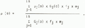
The index j characterizes the droplet diameter category, and ranges from 1 to 15 when the corresponding droplet diameter ranges from 3 to 45 μm, mj is the liquid water mass of a droplet of diameter dj, fj is the fraction of the total concentration consisting of the jth size category, Gj(θ) is the local collection efficiency of droplets of diameter dj, and pj(θ) is the local density calculated for the jth category impinging at the angle θ.
It is assumed that freezing is an individual process for droplets and that droplets remain approximately spherical on freezing. This assumption is valid if the impact speed and the surface temperature are moderately low; under these conditions the ice density ranges from 100 to 700 kg m−3 (Reference MacklinMacklin 1962). For high impact speed and surface temperatures near 0°C, this assumption is no longer justified but the above formula is still valid because, for all droplet categories, the ice density reaches the maximum value of 917 kg m−3.
4.4. Result concerning the variation of the ice density with the angle
Figure 6 shows the variation of ice density against the angle on the cylinder, calculated when parameters are pressure P (850 mbar), temperature T (-10°C), air speed U (20 m s_1),and liquid water content LWC (0.5 g m−3). The cloud droplet spectrum is indicated in the upper right corner of the figure. The vertical scale is the frequency distribution of the concentration; each size category is 3 μm wide and is plotted horizontally from 3 to 30 μm. The median volume diameter is 13 μm. Figure 6 shows that the ice density decreases from 605 kg m−3 at the stagnation line value, to 110 kg m−3 at the maximum impinging angle θM = 65°.
Ice density variation with the angle of impact S on the cylinder and the corresponding input droplet spectrum.

5. Effect of the Density Variation on the Predicted Profile
5.1. Sensitivity to the droplet spectrum
The variation of ice density depends on various parameters such as pressure, temperature, air speed, liquid water content, and droplet distribution. The role of each parameter has been studied, and we focus our attention in this paper on the influence of the droplet spectrum.
figures 7 and 8 illustrate the results of simulations performed for various droplet spectra; the other parameters are identical with those of Figure 6. Three spectra, (a),(b), and (c), are displayed in the upper right corner of Figure 7, The median volume diameters are 9, 13, and 23 um, respectively. These values are representative of the range of spectra encountered during the measurements. The corresponding curves of the ice density variation are also labelled (a), (b), and (c).
Ice density variations with the angle of impact on the cylinder for three cloud droplet spectra. Other conditions identical to Figure 6.

Simulated ice profiles for a duration △t = 10 mn. Thick lines represent densities of Figure 7; thin lines represent fixed density.

The simulated profiles calculated for cases (a), (b), and (c) are represented by the thick lines in Figure 3. The thin lines correspond to simulations with a fixed density (890 kg m−3), as proposed by Lozowski and others (1979). The most important difference between the two simulations concerns the tnickness of the ice deposit. For (a), the calculated density is about three times smaller than the fixed density; then the thickness of ice is three times larger. The shape of the ice deposit changes from sharp-pointed for (a), to flat for (b), and to elliptical for (c), when the median volume diameter varies from 9, 13 and 23 μm, respectively. This means that a flat deposit is observed for a specific droplet spectrum (median volume diameter equal to 13 μm in this case), when the other parameters are fixed. From Figure 7, the forecasted flat deposit (b) is associated with a quasi-linear decrease of the ice density with the angle; by contrast, the curves (a) and (c) show a lower decrease than curve (b). 5.2. Comparison between the new predicted profiles and the observed profiles figures 9 and 10 display the variation of ice density with the angle and the predicted profiles, respectively, for the experimental measurements presented in Figure 1. Figure 9 indicates that the ice density decreases slowly from the stagnation line to the angle 6 θ 55°, from 815 to 500 kg m−3 for case (a) and from 662 to 333 kg m−3 for case (b), respectively. Then the ice density decreases quickly to the values 185 and 113 kg m−3 for the angle 65° (case (a)) and 60° (case (b)), respectively.
Ice density variations with the angle of impact on the cylinder calculated for curves (a) and (b) with the meteorological parameters described in (a) and (b) in Figure 1, respectively.

Simulated ice profile. Thick lines represent densities of Figure 9; thin lines represent fixed density.

From Figure 10, the simulated profiles obtained with a variable density are larger than those obtained with the constant density (890 kg m−3), but they still have an elliptical shape which was not observed during the experiment. We notice that the decrease of the ice density is not quasi-linear and that the most important density variations are in the sectors where the ice growth fluxes are the smallest. This result seems to indicate that the ice density variation cannot explain the differences between the shape of the observed ice deposit of (b) in Figure 1 and the predicted shape of (b) in Figure 7.
As suggested in section 3, the ice density variation is not the only effect involved in the flattening and widening of a profile. In order to produce a realistic result, this effect has to be taken into account at the same time as a variation in the local collection efficiency due to the time evolution of the profile. In fact, these effects are linked; a variation in the local collection efficiency Gj(θ) induces a local density variation (see Equation (2)) and changes the profile, inducing a new variation in the collection efficiency, and so on. Ackley and Templeton (1979) indicate a decrease of the total collection efficiency of small droplets impinging on an elliptical profile with the increase of the eccentricity. For any observed profile the calculations are more difficult than for the elliptical shape and have not yet Been done. Moreover, it is difficult to guess the effect of this variation because the local collection efficiency Gj(θ) is involved, firstly, in the evaluation of the local ice density (directly in Equation (2) and also indirectly through the surface temperature Ts( θ) used to express pj(θ)) and, secondly, in the determination of the ice growth flux R (see Equation (1)) on which the plot of the ice profile depends.
It must be pointed out that for the examples presented in figures 9 and 10 the droplet spectra used in the simulation are the spectra measured by the PMS ASSP-100. Pinnick and others (1981) show that the droplet size measured by the probe is inaccurate for a diameter <8 μm, this corresponds to the first three channels of the probe. The small error in the measured spectra may contribute to the difference between the observed and the simulated profiles.
6. Conclusions
Experiments on icing have been performed on rotating and fixed cylinders in a wind tunnel. Measurements of ice density on the rotating cylinder indicate a rather good agreement with Macklin’s results (1962) and lead us to use his formulation of ice density as a function of (!-rV0/Ts).
The profiles of the ice deposits on the fixed cylinder are compared to the results of simulations by using a model developed by Lozowski and others (1979). In order to improve this simulation, we have introduced the ice density variation as a function of the cylinder angle. This calculation is found to be very sensitive to the cloud droplet spectrum. In some cases this calculation leads to the simulation of a flat profile of the ice deposit, but in other cases this new formulation is not sufficient and it may be necessary to take the time evolution of the profile into account. Continuation of the work described in this paper is now under consideration.
Acknowledgements
The authors would like to express their appreciation to Professor Soulage for his guidance during the period of this study, to Professor Coulman for his comments on the manuscript, and to Dr Pointin for helpful discussions. They are indebted to Dr Ramond, Director of the Institut et Observatoire de Physique du Globe, Clermont-Ferrand, for allowing them to use the observatory at the summit of Puy de Dome for their experiments. Thanks are due to the technical staff of the Laboratoire Associé de Météorologie Physique, Université de Clermont II.
The research was supported by the Direction des Recherches Etudes et Techniques under contract no. 81.34.646.


