
I. INTRODUCTION
Watching in three-dimension (3D) with the freedom to select the desired viewpoint has become possible using free-viewpoint video [Reference Tanimoto1–Reference Smolic5] technologies. For free-viewpoint image synthesis, multi-view-video-plus-depth (MVD) representation is commonly used. Using the color-plus-depth data, synthesizing free-viewpoint images [Reference Fehn6–9] is a straightforward approach. The process is as simple as back-projecting image pixels to the 3D space using per-pixel depth information and rendering them from the virtual viewpoint. This process is often referred to as 3D warping [Reference Mark, Mcmillan and Bishop10] or depth-image-based rendering (DIBR) [Reference Fehn6]. However, when the virtual viewpoint image is physically far from the reference viewpoints, naïve 3D warping cannot produce high-quality virtual viewpoint images, due to holes created by 3D warping. A free-viewpoint image generated by naïve 3D warping has disocclusion holes and non-disocclusion holes due to insufficient sampling. Daribo and Pesquet-Popescu [Reference Daribo and Pesquet-Popescu11], Ahn and Kim [Reference Ahn and Kim12], and Reel et al. [Reference Reel, Cheung, Wong and Dooley13] proposed depth aware approach to fill the disocclusion holes. Some of those have been practically implemented in MPEG View Synthesis Reference Software (VSRS 4.0) [9]. Note that filling disocclusion hole [Reference Daribo and Pesquet-Popescu11–Reference Reel, Wong, Cheung and Dooley15] is not the focus of this paper.
The main focus of this paper is filling holes due to limited sampling density. However, holes due to limited sampling density become larger when the free viewpoint image is physically far from the reference viewpoint images in the synthesis process. With the 3D warping method, limited sampling intensity isolates 3D points reconstructed from color-plus-depth data, i.e., the points are not connected with each other before 3D warping. Hence, it is necessary for 3D points to be connected before synthesizing a virtual image located far from the reference viewpoints.
To eliminate non-disocclusion holes related to limited sampling density, segment the depth map before being used for 3D warping and the other methods apply depth filter and fill these holes. Both approaches deals with depth map. Mao et al. [Reference Mao, Cheung, Ortega and Ji16,Reference Mao, Cheung and Ji17] proposed filling holes due to limited sampling density based on a method that is initially proposed for depth adaptive depth coding [Reference Shen, Kim, Narang, Ortega, Lee and Wey18]. Mao et al. have improved their approach and recently presented it in [Reference Mao, Cheung and Ji19]. Methods in [Reference Fehn6, Reference Mori, Fukushima, Yendo, Fujii and Tanimoto7, Reference Zhang and Tam20–Reference Lee24, Reference Tian, Lai, Lopez and Gomila26] perform depth smoothing after 3D warping. Generally methods that perform depth smoothing introduce artifact.
On the other hand, our proposed method can synthesize a high-quality free-viewpoint image when it is physically far from the reference viewpoint images. Our method detects the connected pixels using depth and color-based criteria. This method creates superpixel by segmentation based on simple linear iterative clustering (SLIC) [Reference Radhakrishna27], which uses both color and depth information (two criteria). We also propose K- means-based interpolation method. The presented study is based on our previous studies [Reference Tezuka, Takahashi and Fujii28, Reference Tezuka, Panahpour Tehrani, Suzuki, Takahashi and Fujii29], in which SLIC-based segmentation was used to determine inter-pixel connections in 3D warping.
For viewing synthesis based on superpixel segmentation, we may refer to methods proposed by Chaurasia et al. [Reference Chaurasia, Duchene, Sorkine-Hornung and Drettakis30], Buyssens et al. [Reference Buyssens, Daisy, Tschumperlé and Lézoray31], and Schmeing and Jiang [Reference Schmeing and Jiang32]. These works introduce the concept of superpixel [Reference Tian, Lai, Lopez and Gomila26–Reference Tezuka, Takahashi and Fujii28] to view synthesis in different viewpoints from our proposed method. Method by Chaurasia et al. [Reference Chaurasia, Duchene, Sorkine-Hornung and Drettakis30] applies superpixel approach to Image Based Rendering (IBR), i.e. rendering without depth data, by over segmenting the image into superpixel, which facilitates the geometry reconstruction for view synthesis based on point cloud representation of the scene. Buyssens et al. [Reference Buyssens, Daisy, Tschumperlé and Lézoray31] method is also based on superpixel over segmentation of both the original and synthesized views and focused on disocclusion holes.
Approach by Schmeing and Jiang [Reference Schmeing and Jiang32], is considered close to our approach, but superpixel segmentation is used after naïve 3D warping and it is applied to warped views, while in our method we perform such segmentation in both depth and color content before 3D warping. Additionally, recent work by Mao et al. in [Reference Mao, Cheung and Ji19] has similarity to this work. In their work, the improved view synthesis was also targeted for any camera arrangement, and for virtual viewpoint far from reference views. In their paper, a superpixel is defined as a patch. The patches are filled up by patch-based maximum a posteriori problem, in which the graph signal processing is used to define graph-signal smoothness prior to regularize the inverse problem. However in our method we detect superpixel (i.e. patch in [Reference Mao, Cheung and Ji19]) by segmentation based on SLIC [Reference Radhakrishna27] using both color and depth information (two criteria), and fill them by K- means-based interpolation. These patches are appropriately spaced using diamond tiling, while the superpixel in our paper does not have any specific shape.
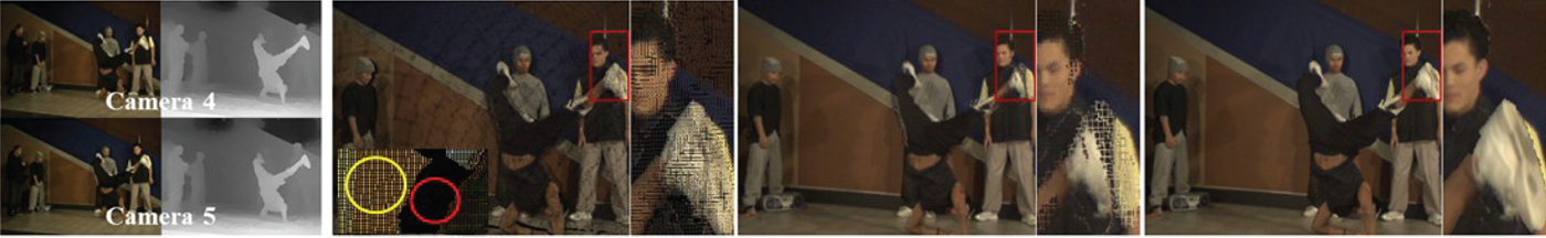
Compared with current benchmark for viewpoint synthesis [9], our method allows high-quality free viewpoint image synthesis and the filling of holes due to limited sampling density with fewer artifacts, even when the synthesized free viewpoint image is physically far from the reference viewpoints. Our method can be considered having not only high quality of view synthesis, but also potential simplicity in the approach, allowing implementation for fast view synthesis. A summary of the results of our method in comparison with other methods is presented in Fig. 1.
Examples of synthesized virtual viewpoints. From left to right: input image + depth data (“breakdancers”, top: camera 4, bottom: camera 5), naïve 3D warping [10], area highlighted with yellow circle shows the holes with limited sampling density, and area highlighted with red circle is disocclusion hole (right: close-up), MPEG view synthesis reference software, VSRS 4.0 [9] (right: close-up), and proposed method (right: close-up).
The paper is organized as follows. We explain the proposed method in Section II and discuss the experimental results in Section III. We conclude the paper in Section IV.
II. PROPOSED METHOD
We propose a method for free-viewpoint image synthesis that can effectively and accurately fill the holes due to limited sampling density. We assume that MVD is given as inputs (references). Our method involves three steps, as illustrated in Fig. 2.
Overview of our proposed free-viewpoint image synthesis method.
First, the color-plus-depth data from the reference viewpoint are 3D warped to the virtual viewpoint. In this process, we use the depth differences among neighboring pixels and perform superpixel segmentation based on SLIC [Reference Radhakrishna27]. The pixel pairs that have small depth differences or reside in the same superpixels are connected, and the polygons enclosed by the connected pixels are inpainted by K- means-based interpolation, which greatly reduces the number of holes. This warping process is performed individually for each viewpoint from which the color-plus-depth data are provided, resulting in several images at the virtual viewpoint that are warped from reference viewpoints that consist of superpixels as image elements rather than individual pixels.
Second, we merge the warped images from the two nearest reference views to obtain the free viewpoint image. Thanks to the data provided from the two reference viewpoints, the result has less noise and holes compared with that from single viewpoint information [Reference Tezuka, Takahashi and Fujii28]. However, the disocclusion holes remain unfilled. These holes are filled by the warped image from other reference viewpoints. Finally in the third step, the remaining holes are filled by inpainting, which is usually used to erase the obstacles or recover damaged parts in an image, as used in VSRS 4.0 [9].
A) Filling non-disocclusion holes due to limited sampling density by superpixel generation and 3D warping
We now explain step 1 in Fig. 2. The color-plus-depth data of each viewpoint are 3D warped to the location of the free-viewpoint image. We back-project the color-plus-depth data into the 3D space to obtain a 3D point cloud to determine which neighbor pixels should be connected or kept isolated. The neighbor pixels that are located on the same object should be connected and the gap between them should be filled. Meanwhile, disocclusion boundaries between the pixels should be kept unfilled because they are physically separated. To achieve this selective connection and fill the holes due to limited sampling density, we propose two criteria corresponding to depth- and color-based segmentation of pixel, respectively. These criteria are described as follows.
Criterion 1 (Superpixel by Depth Segmentation): The first criterion considers the difference in depth values between each pair of pixels. It comes from the observation that disocclusion holes' boundaries usually correspond to edges in the depth map. Therefore, when the depth differences between each pair of neighbor pixels are larger than a threshold value, these pixels are kept isolated; otherwise, they are connected. However, it is difficult to determine the optimal threshold value that can perfectly identify the occlusion boundaries. Moreover, continuous surfaces that are slanted against the imaging plane of the camera exhibit large depth variations and divided into many fragments. Therefore, this criterion alone does not work well, so we combine it with the second criterion.
Criterion 2 (Superpixel by Color Segmentation): The second criterion uses color superpixel segmentation similar to our previous study [Reference Tezuka, Takahashi and Fujii28]. The color-plus-depth data are used to construct segments using SLIC [Reference Radhakrishna27]. The neighbor color pixels are connected if they fall on the same segment; otherwise, they are kept isolated. To improve connection accuracy, we perform SLIC segmentation several times with different segment numbers and combine the results. More precisely, a pair of neighbor color pixels is kept isolated if and only if they never fall on the same segments for all of the segmentation results. However, this criterion alone is not perfect because continuous surfaces are divided into fragments if they have strong color changes.
These two criteria are combined to compensate each criterion's drawbacks. A pair of neighbor pixels is finally connected if they are determined to be connected in accordance at least one of the criteria. In other words, they are kept isolated only if they are determined to be isolated in accordance with both criteria. The polygons enclosed by the connected pixels are inpainted using linear interpolation of the pixels. The 3D points that are isolated and do not belong to either criteria are removed. Such 3D points are likely due to depth errors in the boundary area. Consequently, we remove these errors to improve the quality of free viewpoint image synthesis.
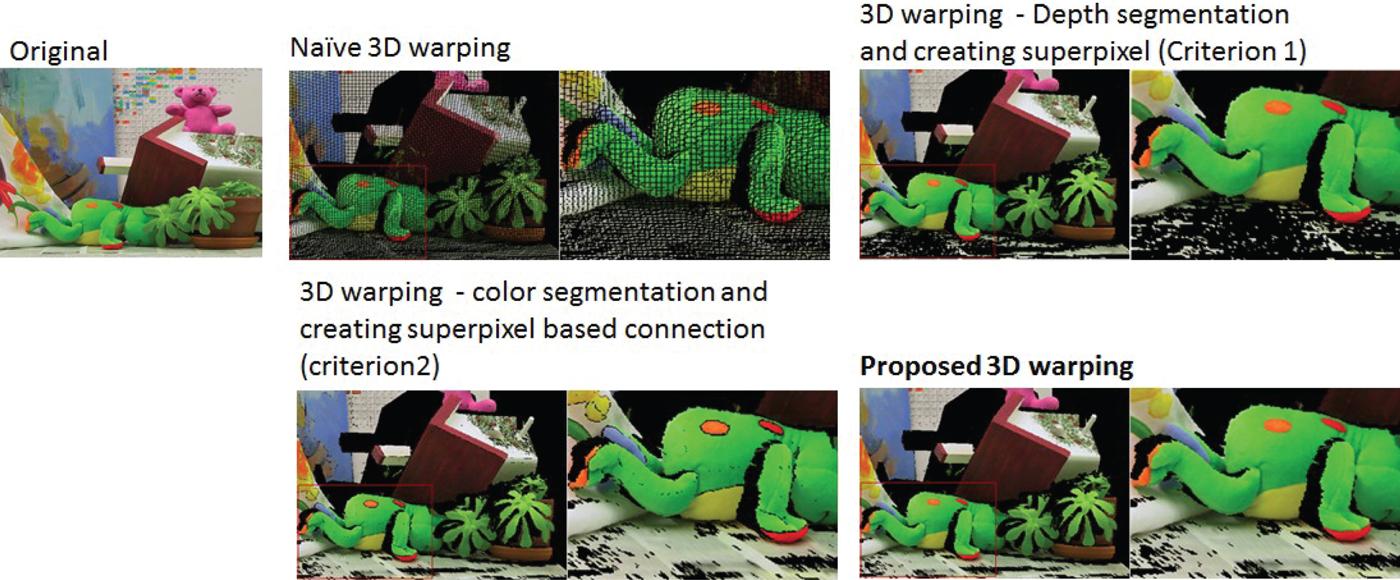
Figure 3 shows the free viewpoint images generated from single-color-plus-depth data, using naïve 3D warping, superpixel segmentation based on criterion 1, superpixel segmentation based on criterion 2, and superpixel segmentation based on criterion 1 and 2 (proposed method). Naïve 3D warping without hole interpolation results in many holes. The floor area is not interpolated well using only criterion 1 but is improved by 3D warping with the criterion 2. However, the color boundaries are not interpolated, even if they are on the same surface in using only a criterion. Finally, the proposed method, which combines the two criteria, yields the best result, as shown at the bottom of Fig. 3.
3D warping using our proposed method in comparison with other methods.
B) Filling disocclusion holes by blending
In this sub-section, we explain step 2 in Fig. 2. We blend two warped images from the two nearest viewpoints to the virtual viewpoint [Reference Mori, Fukushima, Yendo, Fujii and Tanimoto7, Reference Tian, Lai, Lopez and Gomila26] to obtain the virtual viewpoint that has fewer holes. First, we compare depth values of the two warped images at each pixel. If the depth difference is larger than a threshold, we take the pixel that is closer to the free viewpoint. Otherwise, we blend two pixels that are proportional to the distances from the original viewpoints and free viewpoint.
Furthermore, we detect the remaining holes in this step. In this additional process, we use the warped images of the other closest viewpoints, except the nearest left and right viewpoints, to fill the remaining holes, as shown in Fig. 2.
With this blending process, we can also detect potential disocclusion holes using the edge of warped depth maps. We avoid blending in the area where only one of the warped depth maps contains edge information. If the depth values in the detected area are close, we output a warped image of the reference viewpoint without edge information. Otherwise, we output a warped image of the reference viewpoint with a depth value closer to the free viewpoint. This is conceptually similar to our previous work [Reference Tezuka, Takahashi and Fujii28] but in a very simpler and relatively efficient framework.
C) Inpainting of remaining holes in blended image
This step corresponds to step 3 in Fig. 2. In the previous step, some disocclusion holes are filled by the other camera viewpoints during the blending process. However, some other disocclusion holes that come among reference viewpoints remain unfilled. Therefore, all remaining holes are filled using an inpainting method [Reference Lee and Ho33–Reference Telea35], which is usually used to erase the obstacles or recover damaged parts in an image. With our method, we use depth-aware texture selection, VSRS 4.0 [9].
III. EXPERIMENTAL VERIFICATION
In our experiment, we used MVD data [36] provided for MPEG by Nagoya University and NICT [36], and Breakdancers by Microsoft [Reference Zitnick, Kang, Uyttendaele, Winder and Szeliski37]. We evaluated the performance of free viewpoint image synthesis of the naïve 3D warping method [Reference Mark, Mcmillan and Bishop10], VSRS 4.0 [9], and our proposed method. The VSRS 4.0 synthesizes a free viewpoint image by naïve 3D warping, enhanced by warped-depth smoothing filtering to remove the disocclusion holes [Reference Mori, Fukushima, Yendo, Fujii and Tanimoto7, Reference Tian, Lai, Lopez and Gomila26], boundary noise removal [Reference Chen, Chang, Lon, Ding and Chen21], filtering, blending, and inpainting [Reference Daribo and Pesquet-Popescu34, Reference Telea35].
A) Evaluation of free-viewpoint image
For this part of the experiment, we used two types of data, shown in Fig. 4 and listed in Table 1. Computer Graphics MVD (CG MVD) were used to objectively evaluate the performance of our proposed method. The CG MVD contains ground truth depth maps. The other type of data is captured multi-view images and estimated depth maps [38–Reference Boykov, Veksler and Zabih40]. The results of our experiment using captured multi-view images contain only the subjective performance of our proposed free-viewpoint image synthesis method.
Examples of input view-plus-depth-data set used through experiments.
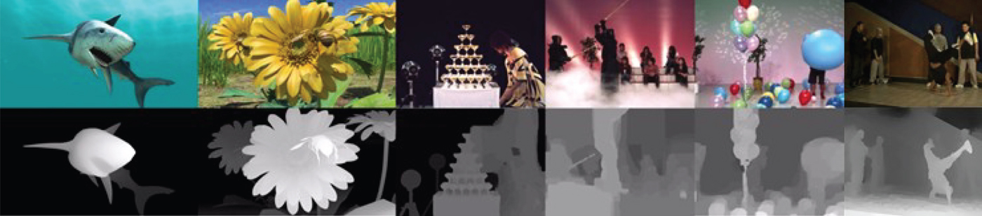
Specification of test sequences used in the experiments [36, Reference Zitnick, Kang, Uyttendaele, Winder and Szeliski37].
Evaluation Using CG-Color-Plus-Depth Maps: We used the MPEG CG test sequences “Bee” ( $1920 \times 1088$
) and “Shark” (
$1920 \times 1088$
) and “Shark” ( $1920 \times 1088$
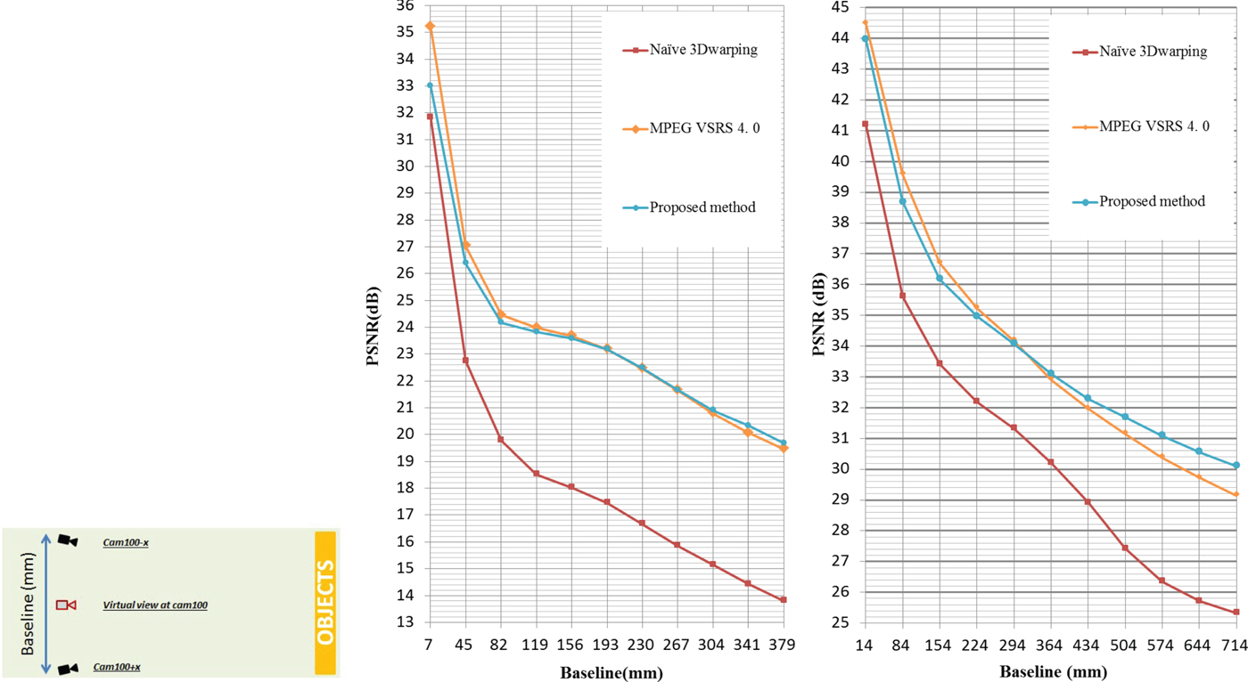
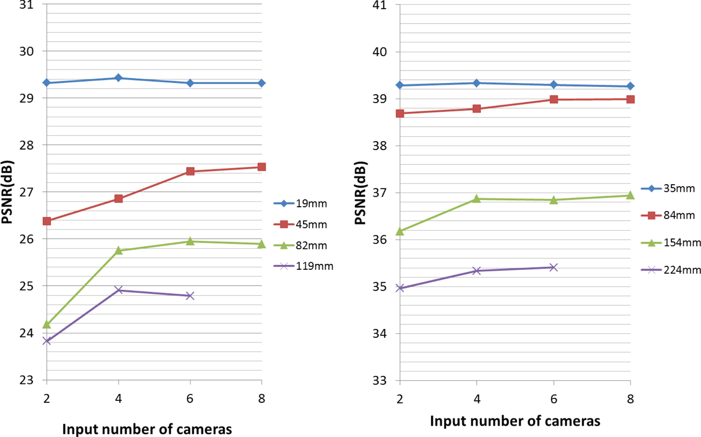
) provided by NICT [36]. These sequences contain 185 viewpoint images and their ground truth depth maps [38–Reference Boykov, Veksler and Zabih40]. The camera baseline (interval) for “Bee” sequence is 3.211 mm and for “Shark” sequence is 7 mm. The objects in “Bee” sequence are located between 735 and 2500 mm from the camera array. The objects in “Shark” sequence are located between 1380 and 3800 mm from camera array. A free-viewpoint image was generated at the viewpoint of camera 101. The inputs were two viewpoints located at the left and right of camera 101 with equal distances to camera 101. The free-viewpoint images were synthesized with different baselines (with different reference viewpoints located with equal distance at left and right side of the free viewpoint) and Z values (the larger Z value, the closer the free-viewpoint image gets to the objects). Examples of an input view-plus-depth-data set and ground truth free viewpoint images (where the Z value is zero) are shown in Fig. 4. Figure 5 shows the Peak Signal to Noise Ratio (PSNR) when the Z value is zero.
$1920 \times 1088$
) provided by NICT [36]. These sequences contain 185 viewpoint images and their ground truth depth maps [38–Reference Boykov, Veksler and Zabih40]. The camera baseline (interval) for “Bee” sequence is 3.211 mm and for “Shark” sequence is 7 mm. The objects in “Bee” sequence are located between 735 and 2500 mm from the camera array. The objects in “Shark” sequence are located between 1380 and 3800 mm from camera array. A free-viewpoint image was generated at the viewpoint of camera 101. The inputs were two viewpoints located at the left and right of camera 101 with equal distances to camera 101. The free-viewpoint images were synthesized with different baselines (with different reference viewpoints located with equal distance at left and right side of the free viewpoint) and Z values (the larger Z value, the closer the free-viewpoint image gets to the objects). Examples of an input view-plus-depth-data set and ground truth free viewpoint images (where the Z value is zero) are shown in Fig. 4. Figure 5 shows the Peak Signal to Noise Ratio (PSNR) when the Z value is zero.
PSNR with different baselines and Z = 0 (left: “bee”, right: “shark”). Camera configuration for this experiment is shown next to the graphs.
For small baseline, holes due to non-disocclusion can be filled by view blending, as shown in Fig. 6. However, when the baseline is large, view blending cannot fill up most of the holes due to non-disocclusion. These holes are further considered as disocclusion holes and are filled up by post processing tools, e.g. boundary noise removal [Reference Park22], filtering, blending, and inpainting [Reference Daribo and Pesquet-Popescu34, Reference Telea35] in VSRS. Consequently, artifacts are appeared in the synthesized image, as shown in Fig. 6. Therefore, proposed method has significant impact on improving the quality of the synthesized image, when the baseline distance is large for the reference cameras. More supporting experimental results are shown in the following sections.
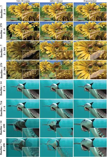
Results of free-viewpoint image generated at edge area (top: baseline 7 mm, bottom: baseline 379 mm). From left to right: ground truth, naïve 3D warping, MPEG VSRS, and proposed method. The camera configuration is similar to the configuration depicted in Fig. 7.
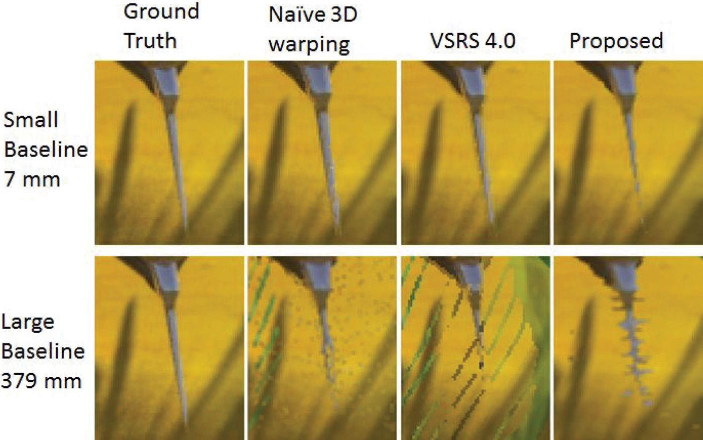
Moreover, for the large baseline, the proposed method exhibited a higher PSNR than VSRS 4.0. However, when the baseline was small, MPEG VSRS 4.0 exhibited the better PSNR. This is because VSRS 4.0 could remove depth errors naturally by using the warped-depth smoothing filter. The proposed method removed the isolated 3D points as depth errors in the edge area when the baseline and Z value were small (shown in Fig. 6). When the baseline and Z value were large, isolated points of an object's surfaces, which are not errors, were also removed using the warped-depth smoothing filter in VSRS 4.0. Therefore, VSRS 4.0 reduces the quality of the free-viewpoint images. According to Fig. 6, the proposed method could interpolate the isolated points as the object's surfaces, but it could not remove depth errors in the edge areas. The remaining artifacts with the proposed method in Fig. 6 were due to misdetection of 3D points, which are actually depth errors, as slanted surfaces. Therefore, a more robust method that can detect depth errors is necessary. One straight forward solution to this problem will be adding the boundary noise removal [Reference Park22], implemented in VSRS, into our algorithm. However, to be able to distinguish the essential performance of our proposed method, we have decided to keep other existing tools excluded in our algorithm. Obviously, combining boundary noise removal [Reference Park22] into our algorithm will definitely improve the quality of the synthesized image in both small and large baselines.
Although the difference in the objective evaluation seems small, we observed significant improvement from the subjective evaluation. Figure 7 shows ground truth, the reference viewpoint (cameras), and camera configuration used in the experiments shown in Fig. 8. Figure 8 shows the results of free-viewpoint images synthesized with each method. Naïve 3D warping generated many holes due to common disocclusion holes of reference viewpoints and sparse or limited density of warped pixels, i.e., sampling density, when the baseline or Z value was large. VSRS 4.0 filled the holes formed due to limited sampling density with a smoothing filter. This works well when there are not many of these holes. However, VSRS 4.0 reduces the quality of the free-viewpoint images when there are many of these holes, i.e., when the baseline or Z value is large. This is due to the fact that the smoothing filter actually enlarges the holes. Compared with VSRS 4.0, the proposed method can synthesize higher quality free-viewpoint images for a large baseline or Z value.
Ground truth, the reference viewpoint (cameras) and camera configuration used in the experiments of Fig. 8.
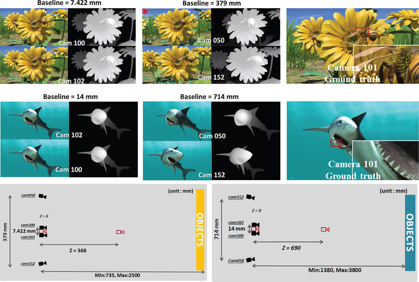
Subjective results of free views synthesized with each method. Demo videos for these sequences are in Supplementary Videos 1 and 2. The reference viewpoints used in this experiment are shown in Fig. 4. The unit is mm.
Evaluation Using Captured Left and Right [View-Video-Plus-Estimated-Depth Maps]: We also synthesized free-viewpoint images with large viewpoint changes using real images and estimated depth maps [Reference Telea35, 38, Reference Szeliski39] of test sequences “Kendo” $\lpar 1024 \times 768\rpar $
, Balloons”
$\lpar 1024 \times 768\rpar $
, Balloons” $\lpar 1024 \times 768\rpar $
, and “Champagne Tower”
$\lpar 1024 \times 768\rpar $
, and “Champagne Tower” $\lpar 1280 \times 960\rpar $
provided by Nagoya University [Reference Szeliski39] and “Breakdancers”
$\lpar 1280 \times 960\rpar $
provided by Nagoya University [Reference Szeliski39] and “Breakdancers” $\lpar 1024 \times 768\rpar $
provided by Microsoft Research [Reference Zitnick, Kang, Uyttendaele, Winder and Szeliski37].
$\lpar 1024 \times 768\rpar $
provided by Microsoft Research [Reference Zitnick, Kang, Uyttendaele, Winder and Szeliski37].
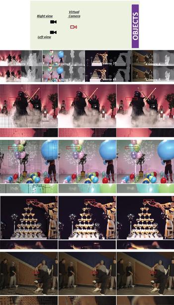
Note that these test sequences have depth maps for a limited number of viewpoints; therefore, this experiment produced only the result when the free-viewpoint image moved forward. Figure 9 shows the reference view-plus-depth data and results of the synthesized free-viewpoint images. Similar to the results of CG test sequences, the subjective results suggest that the proposed method can synthesize at a significantly higher quality than the other methods. However, some artifacts in the form of cracks appeared in the free viewpoint images of “kendo” and “balloons”. This is due to the low quality of the estimated depth data when a free-viewpoint image was generated with a large Z value, i.e., the viewpoint was close to the objects. Due to the low quality of the estimated depth, projection errors occurred. A projection error occurs because of the large color difference of two projected pixel values when they are detected as the same object. A projection error is less significant when the Z value is small since the occluded regions are rather small. However, when the viewpoint greatly changes, the projection error becomes significant due to the wrong estimated depth values. Therefore, high-quality depth data are needed when we synthesize free-viewpoint images that are physically very large distance from reference viewpoint image.
Camera configuration and input reference view + depth data (top, from left to right: “Kendo”, “Balloons”, “Champagne Tower”, and “Breakdancers”), and examples of free-viewpoint images synthesized with each method (bottom, from left to right: naïve 3D warping, MPEG VSRS 4.0, and proposed method). Demo video for Breakdancers (Supplementary Video 3).
B) Evaluation of free-viewpoint image generated by more than two views video and depth maps
We further evaluated our proposed method when more views are involved in view synthesis. We used MPEG CG test sequences “Bee” $\lpar 1920 \times 1088\rpar $
and “Shark”
$\lpar 1920 \times 1088\rpar $
and “Shark” $\lpar 1920 \times 1088\rpar $
provided by NICT since they contain a sufficient number of views and depth maps to evaluate view synthesis using MVD, i.e., more than two color images and depth maps.
$\lpar 1920 \times 1088\rpar $
provided by NICT since they contain a sufficient number of views and depth maps to evaluate view synthesis using MVD, i.e., more than two color images and depth maps.
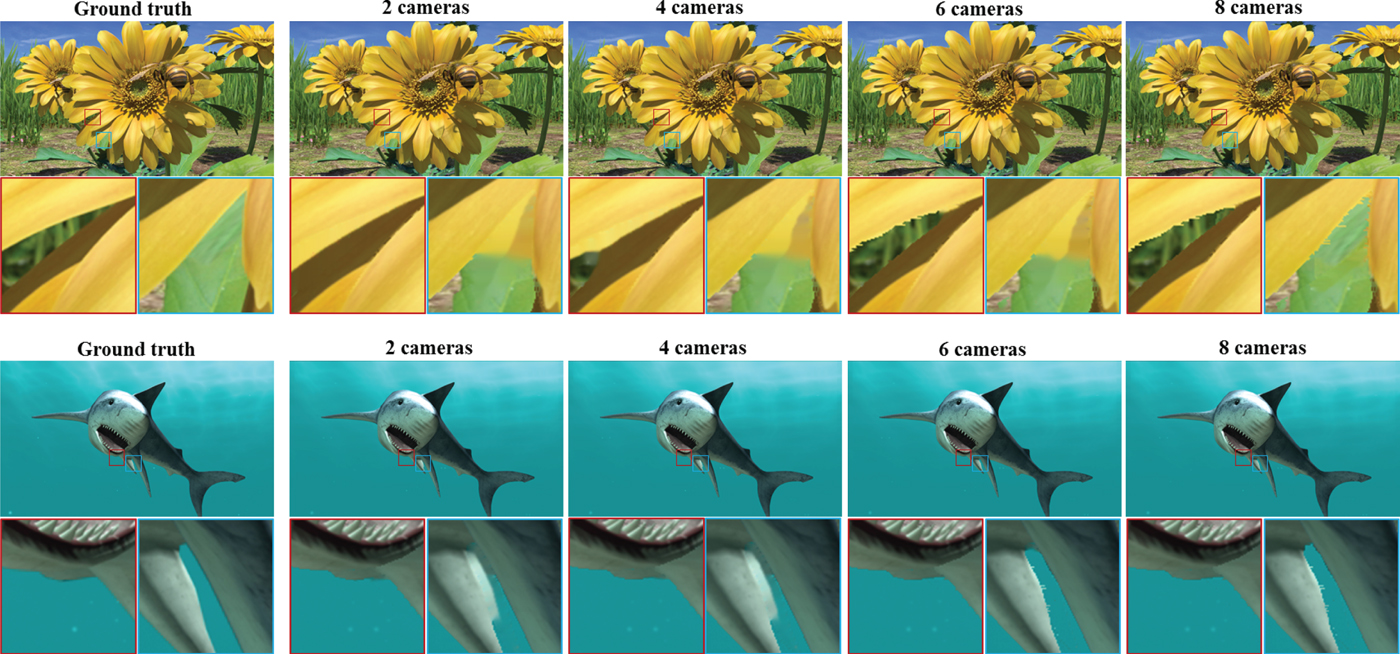
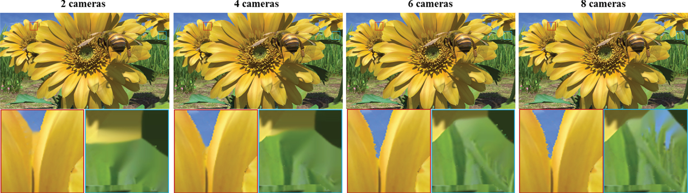
The experiments were conducted using the proposed method and the number of reference views and baseline distance were varied. The generated view was located at camera 101. Figure 10 shows the objective view-synthesis performance of our method. We found that more views are needed to obtain the highest PSNR when the baseline distance between cameras is increased. A PSNR gain of about 2 dB was observed when more than two views were used as reference input views for “Bee”, but for “Shark” the improvement was minor due to the lack of occluded regions, i.e., a less complex scene. Figure 11 shows the subjective results for one of the cases in the graphs of Fig. 10. We observed significant improvement in synthesized image quality and fewer artifacts, especially when more views were involved in synthesizing a free-viewpoint image. Figure 12 shows the forward free-viewpoint image synthesis quality for “Bee” when the Z value was 184 mm and number reference views changed. We observed significant improvement in synthesized image quality when more views were used in the synthesis process.
PSNR using different number of cameras (left: “Bee”, right: “Shark”). The values in the legend shows the baseline distance between each reference viewpoint images.
Synthesized results of using different number of cameras (Top: “Bee”, baseline 45 mm, bottom: “Shark”, baseline 84 mm).
Synthesized results of using different number of cameras (“Bee”, baseline 19 mm).
IV. CONCLUSION
We proposed a high quality method for free-viewpoint image synthesis using multi-view-plus-depth data. The key of the proposed method is hole filling according to the type of hole, while the focus of the paper is on non-disocclusion holes, which are due to limited sampling density during 3D warping. Given, multi-view-plus-depth data, we considered depth and color difference as two criteria to segment pixels into superpixels before 3D warping. Experimental results showed the efficiency and outperformance of our method compared with current methods. For future work, we will focus on the non-linear interpolation method on object surfaces for more natural virtual views. We will also focus on removing the noise in estimated depth maps, which will result in higher quality of free viewpoint image.
SUPPLEMENTARY MATERIAL
The supplementary material for this article can be found at https://doi.org/10.1017/ATSIP.2017.5.
ACKNOWLEDGEMENTS
This work is partially supported by Grant-in-Aid for Scientific Research (C) registered number 16K06349, Japan Society for the Promotion of Science.
Mehrdad Panahpour Tehrani received Ph.D. degree in information electronics from Nagoya University in 2004. From 2004 to 2014, he was affiliated with: Information technology center of Nagoya University as a post-doctoral researcher, KDDI Research as a research associate, Graduate School of Engineering of Nagoya University as an associate professor, and National Institute of Information and Communications Technology (NICT) as a senior researcher. Since 2014, he is a Designated Associate Professor at the Graduate School of Engineering of Nagoya University. His research interests are 3D imaging system with focus on 3D image processing and compression, 3D immersive media processing, intelligent video system and computer vision. He is a member of IEICE, ITE, IPSJ, and IEEE.
Tomoyuki Tezuka received M.Eng in Information Communication from Nagoya University in 2015. He is currently working with KDDI Cooperation. His research interest includes image processing and applications.
Kazuyoshi Suzuki received his Ph.D. in Engineering from Tokyo Institute of Technology in 2006 and received his Ph.D. in mathematical science from Nagoya University in 2012. He is currently a designated assistant professor in Nagoya University. His current research interests are image processing and applications.
Keita Takahashi received his Ph.D. in 2006 from The University of Tokyo. He is currently an associate professor in Nagoya University. Previously, he was affiliated with The University of Tokyo and Tokyo University of Electro-Communications, a project assistant professor and assistant professor, respectively. His main research interests are 3D image processing, compressive sensing, and computational photography.
Toshiaki Fujii received his B.E., M.E., and Dr. E. degrees in electrical engineering from the University of Tokyo in 1990, 1992, and 1995, respectively. From 1995, he has been with the Graduate School of Engineering, Nagoya University. From 2008 to 2010, he was with the Graduate School of Science and Engineering, Tokyo Institute of Technology. He is currently a professor at the Graduate School of Engineering, Nagoya University. His current research interests include multi-dimensional signal processing, multi-camera systems, Multiview video coding and transmission, free-viewpoint video, 3D image processing and compression, compressive sensing and computational photography, and their applications. He is a member of IEICE, ITE, IPSJ, and IEEE.


 Open access