


1 Introduction
In a laser energy power plant, fusion reactions must occur approximately ten times a second, and a free-standing target (FST) transmission line becomes an integral part of any fusion reactor. Developing target fabrication technologies is thus centered on the issues of isotropic fuel layers and high repetition rates, with careful attention paid to an acceptable cost of target fabrication and noncontact delivery at the laser focus[Reference Aleksandrova and Koresheva1–Reference Aleksandrova, Akunets, Koresheva, Koshelev and Timasheva5]. In this report, we discuss the development strategy and future prospects of the FST layering method proposed at the Lebedev Physical Institute for mass target manufacturing for high-repetition-rate facilities: a rate of 5–10 Hz leads to the number of targets (
 $5\times 10^{5}{-}1\times 10^{6}$
) each day. A unique feature of the method is that it works with free-standing and line-moving targets, allowing for the first time starting the development of an FST transmission line with repeatable operation, which is compatible with a noncontact schedule for target delivery to the reaction chamber. A low tritium inventory due to minimization of time and space requirements for all production steps is inherent in the FST layering method as well. In this report, the FST layering time of high-gain direct-drive targets was firstly examined with the aim of reducing it so as to minimize the tritium inventory[Reference Nobile, Schwendt and Gobby6]. Our findings have shown that the FST layering time (
$5\times 10^{5}{-}1\times 10^{6}$
) each day. A unique feature of the method is that it works with free-standing and line-moving targets, allowing for the first time starting the development of an FST transmission line with repeatable operation, which is compatible with a noncontact schedule for target delivery to the reaction chamber. A low tritium inventory due to minimization of time and space requirements for all production steps is inherent in the FST layering method as well. In this report, the FST layering time of high-gain direct-drive targets was firstly examined with the aim of reducing it so as to minimize the tritium inventory[Reference Nobile, Schwendt and Gobby6]. Our findings have shown that the FST layering time (
 $\unicode[STIX]{x1D70F}_{\text{Form}}$
) does not exceed 30 s for D–T fuel. So rapid fuel layering is a necessary condition for producing targets in massive numbers and, very importantly, for producing fuel as isotropic ultrafine layers[Reference Aleksandrova and Koresheva1]. This is due to the fact that progress in plasma implosion up to intense fusion reactions lies in the formation of a given fuel structure that must be isotropic to reach fusion conditions. Therefore, such layers are referred to as advanced materials for cryogenic target fabrication and pioneering the research of laser direct drive using isotropic fuel in target compression experiments.
$\unicode[STIX]{x1D70F}_{\text{Form}}$
) does not exceed 30 s for D–T fuel. So rapid fuel layering is a necessary condition for producing targets in massive numbers and, very importantly, for producing fuel as isotropic ultrafine layers[Reference Aleksandrova and Koresheva1]. This is due to the fact that progress in plasma implosion up to intense fusion reactions lies in the formation of a given fuel structure that must be isotropic to reach fusion conditions. Therefore, such layers are referred to as advanced materials for cryogenic target fabrication and pioneering the research of laser direct drive using isotropic fuel in target compression experiments.
To meet the demand for such targets, the Lebedev Physical Institute (LPI) has made significant progress in technological developments based on advanced fuel layering inside free-standing and line-moving targets – which is referred to as the FST layering method[Reference Aleksandrova and Koresheva1–Reference Aleksandrova, Akunets, Koresheva, Koshelev and Timasheva5]. Moving targets combine all production steps in an FST transmission line that is considered as a potential solution for mass target manufacturing. Besides, minimal time and space scales for fabrication and injection processes allow one to reduce the tritium inventory and to supply targets at the low cost required for economical energy production.
Here we consider the baseline design of a high-gain direct-drive target (
 ${\sim}$
4 mm in diameter) developed by Bodner and coauthors[Reference Bodner, Colombant, Schmitt, Gardner, Lehmberg and Obenschain7] that has a predicted energy gain of 127 using a 1.3 MJ KrF laser (and a gain of 155 using 3.1 MJ). For the 1.3 MJ KrF laser, the target specifications are shown in Figure 1. The vapor cavity has a radius of 1500
${\sim}$
4 mm in diameter) developed by Bodner and coauthors[Reference Bodner, Colombant, Schmitt, Gardner, Lehmberg and Obenschain7] that has a predicted energy gain of 127 using a 1.3 MJ KrF laser (and a gain of 155 using 3.1 MJ). For the 1.3 MJ KrF laser, the target specifications are shown in Figure 1. The vapor cavity has a radius of 1500
 $\unicode[STIX]{x03BC}\text{m}$
. The pure D–T (
$\unicode[STIX]{x03BC}\text{m}$
. The pure D–T (
 $190~\unicode[STIX]{x03BC}\text{m}$
) fuel is surrounded by an ablator that consists of a CH foam (
$190~\unicode[STIX]{x03BC}\text{m}$
) fuel is surrounded by an ablator that consists of a CH foam (
 ${\sim}10~\text{mg}/\text{cm}^{3}$
) filled with frozen D–T (
${\sim}10~\text{mg}/\text{cm}^{3}$
) filled with frozen D–T (
 $261~\unicode[STIX]{x03BC}\text{m}$
). Note that there has been considerable interest regarding the use of foam shells in inertial fusion energy (IFE) targets. A number of methods have been developed for shell production with a CH foam as an ablator material (see, for example, Refs. [Reference Ito, Nagai, Norimatsu, Nikitenko, Tolokonnikov, Koresheva, Fujimura, Azechi and Mima8, Reference Olson, Leeper, Yi, Kline, Zylstra, Peterson, Shah, Braun, Biener, Kozioziemski, Sater, Biener, Hamza, Nikroo, Berzak Hopkins, Ho, LePape and Meezan9]). The ablator is surrounded by a one-micron plastic coating (polystyrene, kapton, etc.) to contain the D–T fuel. The plastic coating is then surrounded by an overcoat of a thin high-Z material such as gold to withstand the thermal chamber environment. We use this target (for simplicity, the BODNER-Target) to examine issues affecting the possibility of its fabrication by the FST layering method.
$261~\unicode[STIX]{x03BC}\text{m}$
). Note that there has been considerable interest regarding the use of foam shells in inertial fusion energy (IFE) targets. A number of methods have been developed for shell production with a CH foam as an ablator material (see, for example, Refs. [Reference Ito, Nagai, Norimatsu, Nikitenko, Tolokonnikov, Koresheva, Fujimura, Azechi and Mima8, Reference Olson, Leeper, Yi, Kline, Zylstra, Peterson, Shah, Braun, Biener, Kozioziemski, Sater, Biener, Hamza, Nikroo, Berzak Hopkins, Ho, LePape and Meezan9]). The ablator is surrounded by a one-micron plastic coating (polystyrene, kapton, etc.) to contain the D–T fuel. The plastic coating is then surrounded by an overcoat of a thin high-Z material such as gold to withstand the thermal chamber environment. We use this target (for simplicity, the BODNER-Target) to examine issues affecting the possibility of its fabrication by the FST layering method.
A high-gain direct-drive target design proposed for a 1.3 MJ KrF laser[Reference Bodner, Colombant, Schmitt, Gardner, Lehmberg and Obenschain7].

The physical layout of the FST formation cycle includes the following stages: (1) fuel filling, (2) fuel layering and (3) target delivery. Filling of the targets is the first stage of the production process. The D–T fuel goes into the target shell and is then layered. For the BODNER-Target, a study of the physical processes which control the D–T-pressurization scheme, including possible damage in the shell material driven by the beta-decay of tritium, is presented in Ref. [Reference Aleksandrova, Koresheva and Koshelev10]. The third stage, noncontact delivery of the BODNER-Target, is analyzed in Ref. [Reference Aleksandrova, Koshelev, Nikitenko, Timasheva and Koresheva11] with detailed conceptual design studies for target transport with levitation. The operational principle is based on a quantum levitation effect of type-II high-temperature superconductors (HTSCs) in a magnetic field. Over the last five years the LPI has made major investments in the hybrid electromagnetic accelerator, which is a combination of the acceleration system (field coils generating the traveling magnetic waves) and the levitation system (permanent magnet guideway (PMG) including a magnetic rail or magnetic track). The obtained results have shown that the HTSCs can be successfully used to maintain friction-free motion of the HTSC-sabots (target carriers) over the PMG, and also to provide the required stability of the levitation height over the whole acceleration length due to a pinning effect. Furthermore, using the driving body from
 $\text{MgB}_{2}$
superconducting coils as a sabot component (critical current 5000 A at magnetic induction 0.25 T) allows one to reach the injection velocity
$\text{MgB}_{2}$
superconducting coils as a sabot component (critical current 5000 A at magnetic induction 0.25 T) allows one to reach the injection velocity
 $200~\text{m}/\text{s}$
under a 400 g overload in a 5 m acceleration length.
$200~\text{m}/\text{s}$
under a 400 g overload in a 5 m acceleration length.
The report describes the latest progress in the development of the second stage – the FST layering of the BODNER-Targets. Fuel layering is an essential step for any IFE target design. The manufacturing requirements (quality of the fuel layer formation) are very strict[Reference Aleksandrova and Koresheva1].
∙ Cryogenic targets must be highly symmetric, have a smooth inner surface of the D–T ice layer, and be at temperatures of approximately 18.3 K before the laser shot to obtain the maximum energy yield from the fusion reaction. Targets must meet exact specifications for the fuel layers.
– Fuel layers must have an acceptable quality with respect to thickness and roughness: the desirable thickness uniformity is less than 1%, and the inner surface roughness is less than 1-
 $\unicode[STIX]{x03BC}\text{m}$
rms (root mean square) in all modes.
$\unicode[STIX]{x03BC}\text{m}$
rms (root mean square) in all modes.
– Fuel layers must be isotropic and free of local defects (e.g., boundary grooves and thermal stress cracks) to ensure that fusion will take place.
– Fuel layers must have adequate thermal and mechanical stability to retain their quality under the processes of target acceleration and injection during delivery. Roughening of the layer surface due to heating during delivery may lead to implosion instabilities.
∙ Layering methods must take into account the specifics of reactor-scaled target fabrication. The most challenging issues in target fabrication for operation at high repetition rates are as follows[Reference Aleksandrova and Koresheva1–Reference Aleksandrova, Akunets, Koresheva, Koshelev and Timasheva5].
– Rapid layering to reduce the tritium inventory in the FST supply system (FST-SS).
– Rapid layering to produce isotropic fuel as ultrafine solid or liquid layers, because, in the equilibrium state, the solid hydrogen isotopes consist of anisotropic molecular crystals[Reference Wanner and Meyer12], and survivability of the fuel layers subjected to environmental effects may depend on the layer structure.
– Moving targets are also necessary to realize repeatable target production at the rates required, their mass manufacture and noncontact delivery.
Below, we report on the FST layering method, which enables the formation of high-quality layers without requiring the application of any other different techniques. This method can be a base for current target supply strategies and future perspectives in IFE research.
2 BODNER-Target fabrication by the FST layering method
In general, IFE research requires cryogenically cooled targets containing layers of deuterium–deuterium (
 $\text{D}_{2}$
) or deuterium–tritium (D–T) fuel, the properties of which can be found in Ref. [Reference Souers13]. We start our work with a BODNER-Target location in the PVT-diagram (Figure 2). To do that it is necessary to estimate its parameters for both fuel types. The obtained results are presented in Table 1 (in view of the data of Figure 1).
$\text{D}_{2}$
) or deuterium–tritium (D–T) fuel, the properties of which can be found in Ref. [Reference Souers13]. We start our work with a BODNER-Target location in the PVT-diagram (Figure 2). To do that it is necessary to estimate its parameters for both fuel types. The obtained results are presented in Table 1 (in view of the data of Figure 1).
The phase state of
 $\text{D}_{2}$
fuel in the BODNER-Target upon cooling down. (a) PVT-diagram (
$\text{D}_{2}$
fuel in the BODNER-Target upon cooling down. (a) PVT-diagram (
 $T_{\text{S}}$
is the temperature of fuel separation into the liquid and vapor phases). (b) Fuel state in the shell just before the FST layering versus the initial target temperature
$T_{\text{S}}$
is the temperature of fuel separation into the liquid and vapor phases). (b) Fuel state in the shell just before the FST layering versus the initial target temperature
 $T_{\text{in}}$
: (1) gaseous fuel (
$T_{\text{in}}$
: (1) gaseous fuel (
 $T_{\text{in}}>T_{\text{CP}}=38.34$
K), (2) compressed liquid (
$T_{\text{in}}>T_{\text{CP}}=38.34$
K), (2) compressed liquid (
 $36.5~\text{K}\sim T_{\text{S}}<T_{\text{in}}<T_{\text{CP}}$
,
$36.5~\text{K}\sim T_{\text{S}}<T_{\text{in}}<T_{\text{CP}}$
,
 $12.5~\text{atm}<P<16.43~\text{atm}$
), (3) liquid
$12.5~\text{atm}<P<16.43~\text{atm}$
), (3) liquid
 $+$
vapor (
$+$
vapor (
 $18.73~\text{K}=T_{\text{TP}}<T_{\text{in}}<T_{\text{S}}$
,
$18.73~\text{K}=T_{\text{TP}}<T_{\text{in}}<T_{\text{S}}$
,
 $P<12.5$
atm).
$P<12.5$
atm).

As shown in Ref. [Reference Olson, Leeper, Yi, Kline, Zylstra, Peterson, Shah, Braun, Biener, Kozioziemski, Sater, Biener, Hamza, Nikroo, Berzak Hopkins, Ho, LePape and Meezan9], the high fill density (
 $\unicode[STIX]{x1D70C}_{\text{f}}$
) needed to realize the mass target parameters (Table 1) requires a high fill pressure (
$\unicode[STIX]{x1D70C}_{\text{f}}$
) needed to realize the mass target parameters (Table 1) requires a high fill pressure (
 $P_{\text{f}}$
), which is equal to
$P_{\text{f}}$
), which is equal to
 ${\sim}$
1100 atm (
${\sim}$
1100 atm (
 $1~\text{atm}=1.013\times 10^{5}~\text{Pa}$
) at room temperature (300 K). The initial pressure in the BODNER-Target (
$1~\text{atm}=1.013\times 10^{5}~\text{Pa}$
) at room temperature (300 K). The initial pressure in the BODNER-Target (
 $P_{0}=1$
atm) can be reached only upon the target temperature decreasing below the critical point (CP) temperature (Table 2) up to the boiling point (BP) temperature (Table 3). At the triple point (TP) the pressure becomes
$P_{0}=1$
atm) can be reached only upon the target temperature decreasing below the critical point (CP) temperature (Table 2) up to the boiling point (BP) temperature (Table 3). At the triple point (TP) the pressure becomes
 ${\sim}$
0.2 atm for all hydrogen isotopes (Table 3).
${\sim}$
0.2 atm for all hydrogen isotopes (Table 3).
Parameters of the BODNER-Target for both
 $\text{D}_{2}$
and D–T fuel.
$\text{D}_{2}$
and D–T fuel.

Critical parameters (density, pressure, temperature) for the hydrogen isotopes[Reference Souers13].

Pressure and temperature for the hydrogen isotopes at the boiling and triple points[Reference Souers13].

As an example, Figure 2 shows the PVT-diagram for
 $\text{D}_{2}$
. The fuel in the shell immediately before FST layering can have different phase states. This issue is also attributed to determining a formation isochore, or to the choice of a parameter
$\text{D}_{2}$
. The fuel in the shell immediately before FST layering can have different phase states. This issue is also attributed to determining a formation isochore, or to the choice of a parameter
 $\unicode[STIX]{x1D703}=\unicode[STIX]{x1D70C}_{\text{f}}/\unicode[STIX]{x1D70C}_{\text{CP}}$
, where
$\unicode[STIX]{x1D703}=\unicode[STIX]{x1D70C}_{\text{f}}/\unicode[STIX]{x1D70C}_{\text{CP}}$
, where
 $\unicode[STIX]{x1D70C}_{\text{CP}}$
is the critical density of the fuel material (Table 2). In the PVT-diagram the parameter
$\unicode[STIX]{x1D70C}_{\text{CP}}$
is the critical density of the fuel material (Table 2). In the PVT-diagram the parameter
 $\unicode[STIX]{x1D703}$
distinguishes three regions (Figure 2) that have a certain influence on the FST layering, namely, the choice of target temperature
$\unicode[STIX]{x1D703}$
distinguishes three regions (Figure 2) that have a certain influence on the FST layering, namely, the choice of target temperature
 $T_{\text{in}}$
at the moment of target entry into the layering channel. In addition, the value of
$T_{\text{in}}$
at the moment of target entry into the layering channel. In addition, the value of
 $\unicode[STIX]{x1D703}$
dictates the temperature dependence of such target parameters as a proportion of the vapor and condensed fuel in terms of volume and mass, the relative thickness of a spherically symmetric layer, and the relative radius of the vapor bubble (
$\unicode[STIX]{x1D703}$
dictates the temperature dependence of such target parameters as a proportion of the vapor and condensed fuel in terms of volume and mass, the relative thickness of a spherically symmetric layer, and the relative radius of the vapor bubble (
 $\unicode[STIX]{x1D6FC}$
), where
$\unicode[STIX]{x1D6FC}$
), where
 $\unicode[STIX]{x1D70C}_{\text{c}}$
is the density of condensed fuel (liquid or solid) and
$\unicode[STIX]{x1D70C}_{\text{c}}$
is the density of condensed fuel (liquid or solid) and
 $\unicode[STIX]{x1D70C}_{\text{v}}$
is the density of saturated vapor:
$\unicode[STIX]{x1D70C}_{\text{v}}$
is the density of saturated vapor:
 $$\begin{eqnarray}\displaystyle \unicode[STIX]{x1D6FC}(\unicode[STIX]{x1D703},T)=\sqrt[3]{\frac{\unicode[STIX]{x1D70C}_{\text{c}}(T)-\unicode[STIX]{x1D703}\unicode[STIX]{x1D70C}_{\text{CP}}}{\unicode[STIX]{x1D70C}_{\text{c}}(T)-\unicode[STIX]{x1D70C}_{\text{v}}(T)}}. & & \displaystyle\end{eqnarray}$$
The formation isochore for the BODNER-Target corresponds to the parameter range
 $\unicode[STIX]{x1D703}>1$
and is equal to 1.54 for
$\unicode[STIX]{x1D703}>1$
and is equal to 1.54 for
 $\text{D}_{2}$
and 1.56 for D–T (i.e.,
$\text{D}_{2}$
and 1.56 for D–T (i.e.,
 $\unicode[STIX]{x1D703}_{\text{D2}}$
and
$\unicode[STIX]{x1D703}_{\text{D2}}$
and
 $\unicode[STIX]{x1D703}_{\text{D{-}T}}$
are practically identical), and the fill pressure is also practically identical
$\unicode[STIX]{x1D703}_{\text{D{-}T}}$
are practically identical), and the fill pressure is also practically identical
 $P_{\text{f}}\sim 1100$
atm (Table 1). Thus, for FST layering, the BODNER-Target with
$P_{\text{f}}\sim 1100$
atm (Table 1). Thus, for FST layering, the BODNER-Target with
 $\text{D}_{2}$
can serve in testing the performance of the FST-SS in the different operational regimes (test modes). This is very important for the following reasons. In contrast to
$\text{D}_{2}$
can serve in testing the performance of the FST-SS in the different operational regimes (test modes). This is very important for the following reasons. In contrast to
 $\text{D}_{2}$
, D–T contains the radioactive tritium (
$\text{D}_{2}$
, D–T contains the radioactive tritium (
 $\text{T}_{2}$
), which requires highly expensive measures for environmental protection. However, since all the units in each FST production step are functionally identical for both fuel types, then most of the FST-SS test modes can be run with
$\text{T}_{2}$
), which requires highly expensive measures for environmental protection. However, since all the units in each FST production step are functionally identical for both fuel types, then most of the FST-SS test modes can be run with
 $\text{D}_{2}$
. Such an approach has particular advantages because it substantially reduces risks during testing and reduces the total cost of development.
$\text{D}_{2}$
. Such an approach has particular advantages because it substantially reduces risks during testing and reduces the total cost of development.
2.1 Fuel layering stage
The FST layering method provides rapid symmetrization and freezing of solid ultrafine fuel layers. (a) Schematic of the FST layering module. (b) Target before layering (‘liquid
 $+$
vapor’ fuel state). (c) Target after FST layering (uniform solid layer). (d) Single-spiral LC (1) in the working assembly. (e) Single-spiral LC (1) shown with magnification. (f) Double-spiral LC.
$+$
vapor’ fuel state). (c) Target after FST layering (uniform solid layer). (d) Single-spiral LC (1) in the working assembly. (e) Single-spiral LC (1) shown with magnification. (f) Double-spiral LC.

The FST layering method is based on rapid fuel cooling via the contact heat conductivity[Reference Aleksandrova and Koresheva1–Reference Aleksandrova, Akunets, Koresheva, Koshelev and Timasheva5]. A batch mode is applied, and high cooling rates (
 $q=1{-}50~\text{K/s}$
) are maintained to form isotropic ultrafine solid layers in moving free-standing targets (Figure 3). During FST layering, two processes are mostly responsible for maintaining uniform layer formation.
$q=1{-}50~\text{K/s}$
) are maintained to form isotropic ultrafine solid layers in moving free-standing targets (Figure 3). During FST layering, two processes are mostly responsible for maintaining uniform layer formation.
– First, as the target rolls along the spiral layering channel, the forced target rotation results in liquid layer symmetrization.
– Second, heat transport outside the target via conduction through a small contact area between the shell wall and the wall of the layering channel (evacuated metal hollow tube, helium-cooled outside) results in liquid layer freezing.
At the same time, high cooling rates (
 $q=1{-}50~\text{K}/\text{s}$
) combined with high-melting-point additives to the fuel content in the range
$q=1{-}50~\text{K}/\text{s}$
) combined with high-melting-point additives to the fuel content in the range
 $\unicode[STIX]{x1D702}=0.5\%$
–25% (neon, argon, tritium) result in the creation of stable, ultimately disordered structures with a high defect density or an isotropic medium. The effect of additives is as follows.
$\unicode[STIX]{x1D702}=0.5\%$
–25% (neon, argon, tritium) result in the creation of stable, ultimately disordered structures with a high defect density or an isotropic medium. The effect of additives is as follows.
– They initiate growth of dislocations that prevent the formation of a coarse-grained crystalline phase and enhance the mechanical strength of the layers.
– They decelerate diffusion transport processes and raise the diffusion activation energy.
– They work as stabilizing agents, keeping the grain size stable, and, as a consequence, maintaining the thermal and mechanical stability of the ultrafine cryogenic layers.
The total layering time for targets of
 ${\sim}$
2 mm in diameter is typically less than 15 s, which is a necessary condition for tritium inventory minimization. An important parameter is the target lifetime within a temperature interval,
${\sim}$
2 mm in diameter is typically less than 15 s, which is a necessary condition for tritium inventory minimization. An important parameter is the target lifetime within a temperature interval,
 $\unicode[STIX]{x0394}T_{\text{ex}}$
, in which a stable ultrafine fuel structure can exist. Our experiments showed that this interval for FST layering,
$\unicode[STIX]{x0394}T_{\text{ex}}$
, in which a stable ultrafine fuel structure can exist. Our experiments showed that this interval for FST layering,
 $\unicode[STIX]{x0394}T_{\text{ex}}=\unicode[STIX]{x0394}T_{\text{FST}}$
, has the largest possible range, from 4.2 K right up to the temperature of solid fuel melting at the triple point. The ultrafine fuel structure presents the challenge of making smooth fuel layers and keeping them smooth under temperature variations (free of local defects). The FST layering method is promising for the formation of a stable ultrafine layer from D–T with the molecular composition: 25%
$\unicode[STIX]{x0394}T_{\text{ex}}=\unicode[STIX]{x0394}T_{\text{FST}}$
, has the largest possible range, from 4.2 K right up to the temperature of solid fuel melting at the triple point. The ultrafine fuel structure presents the challenge of making smooth fuel layers and keeping them smooth under temperature variations (free of local defects). The FST layering method is promising for the formation of a stable ultrafine layer from D–T with the molecular composition: 25%
 $\text{D}_{2}$
, 50% D–T molecules, and 25%
$\text{D}_{2}$
, 50% D–T molecules, and 25%
 $\text{T}_{2}$
. In this case,
$\text{T}_{2}$
. In this case,
 $\text{T}_{2}$
in D–T is considered as a high-melting-point additive with respect to
$\text{T}_{2}$
in D–T is considered as a high-melting-point additive with respect to
 $\text{D}_{2}$
and D–T. Thus, the ultrafine layers obtained by FST are layers which can be referred to as layers with inherent survival features because they have enhanced mechanical strength and thermal stability. This is a significant factor for the retention of layer quality during target delivery[Reference Aleksandrova, Koresheva, Ospov, Timasheva, Tolokonnikov, Panina, Belolipetskiy and Yaguzinskiy4, Reference Aleksandrova, Akunets, Koresheva, Koshelev and Timasheva5].
$\text{D}_{2}$
and D–T. Thus, the ultrafine layers obtained by FST are layers which can be referred to as layers with inherent survival features because they have enhanced mechanical strength and thermal stability. This is a significant factor for the retention of layer quality during target delivery[Reference Aleksandrova, Koresheva, Ospov, Timasheva, Tolokonnikov, Panina, Belolipetskiy and Yaguzinskiy4, Reference Aleksandrova, Akunets, Koresheva, Koshelev and Timasheva5].
Note that a conventional approach to solid layering (known as beta-layering method[Reference Kozioziemski, Mapoles, Sater, Chernov, Moody, Lugten and Johnson.14, Reference Mapoles15]) involves crystallization from a single seed crystal in the fixed target under extremely slow cooling (
 $q\sim 3\times 10^{-5}~\text{K}/\text{s}$
) and precise cryogenic temperature control (
$q\sim 3\times 10^{-5}~\text{K}/\text{s}$
) and precise cryogenic temperature control (
 ${<}100~\unicode[STIX]{x03BC}\text{K}$
) to obtain single-crystal-like layers. In a uniform thermal environment, the beta-layering method can form a spherical fuel layer, but it is not efficient in preventing local defects. The target lifetime (layer roughness is less than 1-
${<}100~\unicode[STIX]{x03BC}\text{K}$
) to obtain single-crystal-like layers. In a uniform thermal environment, the beta-layering method can form a spherical fuel layer, but it is not efficient in preventing local defects. The target lifetime (layer roughness is less than 1-
 $\unicode[STIX]{x03BC}\text{m}$
rms) is of a few seconds after reaching the desired temperature[Reference Mapoles15]. This is a consequence of the D–T layer formed by beta-layering being obtained as a result of an almost equilibrium process of crystal growth, such that all the features of the equilibrium crystalline state are inherent in such a layer, including the temperature-dependent behavior of the local defects on the inner surface of the D–T layer. Besides, the total layering time is more than 24 h. Thus, the beta-layering method is not efficient for mass target fabrication for IFE usage. It is a one-of-a-kind technique, and very expensive[Reference Aleksandrova and Koresheva1, Reference Kozioziemski, Mapoles, Sater, Chernov, Moody, Lugten and Johnson.14, Reference Mapoles15].
$\unicode[STIX]{x03BC}\text{m}$
rms) is of a few seconds after reaching the desired temperature[Reference Mapoles15]. This is a consequence of the D–T layer formed by beta-layering being obtained as a result of an almost equilibrium process of crystal growth, such that all the features of the equilibrium crystalline state are inherent in such a layer, including the temperature-dependent behavior of the local defects on the inner surface of the D–T layer. Besides, the total layering time is more than 24 h. Thus, the beta-layering method is not efficient for mass target fabrication for IFE usage. It is a one-of-a-kind technique, and very expensive[Reference Aleksandrova and Koresheva1, Reference Kozioziemski, Mapoles, Sater, Chernov, Moody, Lugten and Johnson.14, Reference Mapoles15].
In contrast, the FST layering method works with nonfixed moving targets at high cooling rates according to the ‘layering
 $+$
delivery’ scheme. The layering channel is a major element in the practical implementation of this scheme. Figure 3 schematically shows the operational scenario, which is as follows (see details in Refs. [Reference Aleksandrova and Koresheva1–Reference Aleksandrova, Belolipetskiy, Koresheva and Tolokonnikov3]).
$+$
delivery’ scheme. The layering channel is a major element in the practical implementation of this scheme. Figure 3 schematically shows the operational scenario, which is as follows (see details in Refs. [Reference Aleksandrova and Koresheva1–Reference Aleksandrova, Belolipetskiy, Koresheva and Tolokonnikov3]).
– The FST layering module (LM) works with a target batch at one time.
– The transport process is target injection between the basic units of the LM: shell container (SC), layering channel (LC) and test chamber (TC).
– The LC is a special insert into the cryostat, a certain part of which must be at cryogenic temperatures. The medium immediately surrounding the target inside the LC is vacuum (
 ${<}10^{-4}$
Torr, 1 Torr
${<}10^{-4}$
Torr, 1 Torr
 $=$
133.3 Pa).
$=$
133.3 Pa).
– Targets move downwards from the top in the LC in rapid succession, one after another, that allows high repetition rates of target injection to the TC.
– The TC is used for cryogenic target quality control: precise tomography and threshold characterization.
– The TC is a prototypical interface unit between the layering module & target injector (LM&TI).
For IFE usage, such a scenario allows economical fabrication of large quantities of targets for injection at the laser focus. When injecting, the targets will be tracked in flight by on-line holographic methods[Reference Aleksandrova, Koresheva, Koshelev and Ospov2] to provide the data needed for precise target irradiation to achieve ignition and high energy gain.
For a better understanding of the time-integral performance (TIP) criterion for the FST layering, we emphasize that the LC is a special insert into the LM cryostat, a certain part of which must be at cryogenic temperatures. The medium immediately surrounding the target in the LC is a vacuum, and the layering process does not require that the target surface be almost isothermal. For successful FST layering, the LC must have a well-defined geometry in order to satisfy the TIP criterion:
 $$\begin{eqnarray}\unicode[STIX]{x1D70F}_{\text{Form}}<\unicode[STIX]{x1D70F}_{\text{Res}},\end{eqnarray}$$
where
 $\unicode[STIX]{x1D70F}_{\text{Form}}$
is the FST layering time and
$\unicode[STIX]{x1D70F}_{\text{Form}}$
is the FST layering time and
 $\unicode[STIX]{x1D70F}_{\text{Res}}$
is the target residence time in the LC.
$\unicode[STIX]{x1D70F}_{\text{Res}}$
is the target residence time in the LC.
We start our analysis with a target cooling procedure, which is a preparatory stage before the FST layering. After shell filling at 300 K, the SC with the filled shells is transported at the same temperature from the fill system to the LM to carry out the FST layering experiments. Then the SC is cooled down to a certain depressurization temperature
 $T_{\text{d}}$
, which is significantly lower than room temperature. This is required for the SC depressurization stage (i.e., for gas removal from the dead volume of the SC). A level of decrease in temperature should be estimated.
$T_{\text{d}}$
, which is significantly lower than room temperature. This is required for the SC depressurization stage (i.e., for gas removal from the dead volume of the SC). A level of decrease in temperature should be estimated.
The possibility of performing the SC depressurization procedure under conditions excluding both shell damage due to internal pressure and fuel leakage from the shells due to reverse diffusion exists only under a temperature decrease, when the gas pressure drops (Figures 2 and 4), the gas permeability decreases, and the shell material strength rises[Reference Merkuliev, Akunets, Borisenko, Bushuev, Gromov, Dorogotovtsev, Isakov, Koresheva, Nikitenko, Tolokonnikov and Isakov16, Reference Aleksandrova, Koresheva, Koshelev and Nikitenko17]. As the gas pressure in the shell does not depend on the shell material, the possibility of performing one or another variant is determined only by the tensile properties of the shell and its configuration. Two cases are possible for the BODNER-Target upon cooling (Figure 2): at some values of
 $T_{\text{d}}$
, the tensile strength,
$T_{\text{d}}$
, the tensile strength,
 $\unicode[STIX]{x1D70E}_{\text{st}}$
, becomes sufficient for fuel removal from the dead volume of the SC when the fuel is still gaseous, whereas in some cases the necessary pressure drop can be achieved only at
$\unicode[STIX]{x1D70E}_{\text{st}}$
, becomes sufficient for fuel removal from the dead volume of the SC when the fuel is still gaseous, whereas in some cases the necessary pressure drop can be achieved only at
 $T_{\text{d}}<T_{\text{CP}}$
(see Table 2), when the fuel in the SC becomes liquid.
$T_{\text{d}}<T_{\text{CP}}$
(see Table 2), when the fuel in the SC becomes liquid.
The gas pressure in the shell versus the fuel density near the critical point for (a)
 $\text{D}_{2}$
and (b) D–T.
$\text{D}_{2}$
and (b) D–T.

Below we discuss the safe depressurization of the SC, or the BODNER-Target stability during excess gas removal from the SC with the fuel-filled shells at
 $P_{\text{f}}=1100$
atm at 300 K (
$P_{\text{f}}=1100$
atm at 300 K (
 $\text{D}_{2}$
/D–T). The calculations were made according to the following formula:
$\text{D}_{2}$
/D–T). The calculations were made according to the following formula:
 $$\begin{eqnarray}P_{\text{st}}=2\unicode[STIX]{x1D70E}_{\text{st}}\unicode[STIX]{x1D6FF},\end{eqnarray}$$
where
 $P_{\text{st}}$
is the difference in pressure inside and outside the shell just before shell damage occurs, and
$P_{\text{st}}$
is the difference in pressure inside and outside the shell just before shell damage occurs, and
 $\unicode[STIX]{x1D6FF}=\unicode[STIX]{x0394}r/r_{0}$
is the inverse aspect ratio of the shell (
$\unicode[STIX]{x1D6FF}=\unicode[STIX]{x0394}r/r_{0}$
is the inverse aspect ratio of the shell (
 $\unicode[STIX]{x0394}r=r_{0}-r_{1}$
is the shell thickness,
$\unicode[STIX]{x0394}r=r_{0}-r_{1}$
is the shell thickness,
 $r_{0}$
and
$r_{0}$
and
 $r_{1}$
are the outer and the inner shell radii, respectively). In addition, we use the van der Waals equation to impose the condition for depressurization:
$r_{1}$
are the outer and the inner shell radii, respectively). In addition, we use the van der Waals equation to impose the condition for depressurization:
 $$\begin{eqnarray}P=\frac{R_{\text{G}}T}{\unicode[STIX]{x1D707}/\unicode[STIX]{x1D70C}-b}-\frac{a\unicode[STIX]{x1D70C}^{2}}{\unicode[STIX]{x1D707}^{2}},\end{eqnarray}$$
where
 $R_{\text{G}}$
is the gas constant, which is dependent on temperature and density,
$R_{\text{G}}$
is the gas constant, which is dependent on temperature and density,
 $\unicode[STIX]{x1D707}$
is the molecular weight,
$\unicode[STIX]{x1D707}$
is the molecular weight,
 $T$
is the absolute temperature, and
$T$
is the absolute temperature, and
 $a$
and
$a$
and
 $b$
are temperature-dependent parameters. The condition for the SC depressurization can be written in the form of
$b$
are temperature-dependent parameters. The condition for the SC depressurization can be written in the form of
 $$\begin{eqnarray}P(\unicode[STIX]{x1D70C}_{\text{f}},T_{\text{d}})<P_{\text{st}},\end{eqnarray}$$
where
 $P$
is the pressure inside the shell at
$P$
is the pressure inside the shell at
 $T=T_{\text{d}}$
. Using Equations (3)–(5), we determine the reference values, which are the limits for the BODNER-Target to depressurize the SC when the fuel is gaseous (see Figure 4 and Table 4). A generalized value for gas fuel removal at
$T=T_{\text{d}}$
. Using Equations (3)–(5), we determine the reference values, which are the limits for the BODNER-Target to depressurize the SC when the fuel is gaseous (see Figure 4 and Table 4). A generalized value for gas fuel removal at
 $T_{\text{d}}>T_{\text{CP}}$
makes
$T_{\text{d}}>T_{\text{CP}}$
makes
 $\unicode[STIX]{x1D70E}>2500$
MPa, which is almost ten times more than the value given in Ref. [18] (spherical polyimide shells have the following reference data at 300 K: elastic modulus
$\unicode[STIX]{x1D70E}>2500$
MPa, which is almost ten times more than the value given in Ref. [18] (spherical polyimide shells have the following reference data at 300 K: elastic modulus
 ${\sim}$
15 GPa, ultimate tensile strength of 300 MPa, i.e.,
${\sim}$
15 GPa, ultimate tensile strength of 300 MPa, i.e.,
 $P_{\text{st}}=3$
atm). In other words, SC depressurization is possible if the fuel is in the state of ‘liquid
$P_{\text{st}}=3$
atm). In other words, SC depressurization is possible if the fuel is in the state of ‘liquid
 $+$
vapor’ (Figure 2).
$+$
vapor’ (Figure 2).
Depressurization temperature in the case of the BODNER-Target for
 $\text{D}_{2}$
,
$\text{D}_{2}$
,
 $\text{T}_{2}$
and D–T.
$\text{T}_{2}$
and D–T.

Required tensile strength near the critical point temperature.

The calculation results are presented in Figure 5: the values of
 $T_{\text{d}}$
are 27.5 K (
$T_{\text{d}}$
are 27.5 K (
 $P_{\text{d}}=2.66$
atm) for
$P_{\text{d}}=2.66$
atm) for
 $\text{D}_{2}$
and 28 K (
$\text{D}_{2}$
and 28 K (
 $P_{\text{d}}=2.56$
atm) for D–T. They could be improved if we had the necessary, precise information related to the cryogenic tensile properties for the BODNER-Target design. As shown in Ref. [Reference Aleksandrova, Koresheva, Koshelev and Nikitenko17], temperature decreasing may enhance the mechanical behavior of the polymer shells, and the values of
$P_{\text{d}}=2.56$
atm) for D–T. They could be improved if we had the necessary, precise information related to the cryogenic tensile properties for the BODNER-Target design. As shown in Ref. [Reference Aleksandrova, Koresheva, Koshelev and Nikitenko17], temperature decreasing may enhance the mechanical behavior of the polymer shells, and the values of
 $T_{\text{d}}$
could be much higher.
$T_{\text{d}}$
could be much higher.
As the BODNER-Target is cooled, there is a point where the fuel gas in the shell is liquefied (Figure 2). Since solid layer formation must pass through the liquid phase, the time for which the liquid phase exists,
 $\unicode[STIX]{x1D70F}_{\text{Liquid}}$
, is a key parameter and must be sufficient for symmetrization of the cryogenic layer. The initial amount of the liquid fuel before symmetrization depends on
$\unicode[STIX]{x1D70F}_{\text{Liquid}}$
, is a key parameter and must be sufficient for symmetrization of the cryogenic layer. The initial amount of the liquid fuel before symmetrization depends on
 $T_{\text{in}}$
. Shell rotation causes spreading of liquid fuel on the interior of spherical shells (Figure 6(a)), and under certain conditions it results in uniform layer formation (Figure 6(b), see details in Section 3). This important effect (which is referred to as dynamical self-symmetrization) makes it pertinent to study the dynamical spread of the liquid fuel inside the moving target and develop numerical models of the process. The obtained results (theoretical and experimental) can be found in Refs. [Reference Aleksandrova, Bazdenkov and Chtcherbakov19, Reference Aleksandrova, Bazdenkov, Chtcherbakov, Gromov, Koresheva, Koshelev, Osipov and Yaguzinskiy20]. If
$T_{\text{in}}$
. Shell rotation causes spreading of liquid fuel on the interior of spherical shells (Figure 6(a)), and under certain conditions it results in uniform layer formation (Figure 6(b), see details in Section 3). This important effect (which is referred to as dynamical self-symmetrization) makes it pertinent to study the dynamical spread of the liquid fuel inside the moving target and develop numerical models of the process. The obtained results (theoretical and experimental) can be found in Refs. [Reference Aleksandrova, Bazdenkov and Chtcherbakov19, Reference Aleksandrova, Bazdenkov, Chtcherbakov, Gromov, Koresheva, Koshelev, Osipov and Yaguzinskiy20]. If
 $T_{\text{in}}$
is close to
$T_{\text{in}}$
is close to
 $T_{\text{TP}}$
(see Table 3), then layer freezing has begun before the achievement of layer uniformity (Figure 6(c)). Special measures are required to prevent this effect.
$T_{\text{TP}}$
(see Table 3), then layer freezing has begun before the achievement of layer uniformity (Figure 6(c)). Special measures are required to prevent this effect.
Dynamical layer symmetrization during FST layering: (a) schematic of the target rolling along the LC; (b)
 $T_{\text{in}}=21$
K and (c)
$T_{\text{in}}=21$
K and (c)
 $T_{\text{in}}=15$
K show the influence of
$T_{\text{in}}=15$
K show the influence of
 $T_{\text{in}}$
on the layer uniformity. Both targets have the same parameters. But in case (c) during target rolling the liquid
$T_{\text{in}}$
on the layer uniformity. Both targets have the same parameters. But in case (c) during target rolling the liquid
 $\text{H}_{2}$
begins to spread onto the inner shell surface, and as
$\text{H}_{2}$
begins to spread onto the inner shell surface, and as
 $T_{\text{in}}=15$
K is close to
$T_{\text{in}}=15$
K is close to
 $T_{\text{TP}}=13.96$
K for
$T_{\text{TP}}=13.96$
K for
 $\text{H}_{2}$
, then quick freezing has begun before the achievement of layer uniformity.
$\text{H}_{2}$
, then quick freezing has begun before the achievement of layer uniformity.

Technologically, implementation of the dynamical layer symmetrization is provided by precise control of the following parameters of the FST layering method: the initial target temperature,
 $T_{\text{in}}$
, before the FST layering starts, the temperature profile along the LC and the LC geometry for the given target design. In the optimal case, the layer symmetrization time
$T_{\text{in}}$
, before the FST layering starts, the temperature profile along the LC and the LC geometry for the given target design. In the optimal case, the layer symmetrization time
 $\unicode[STIX]{x1D70F}_{\text{Sym}}$
is defined by the ratio:
$\unicode[STIX]{x1D70F}_{\text{Sym}}$
is defined by the ratio:
 $$\begin{eqnarray}\displaystyle \unicode[STIX]{x1D70F}_{\text{Sym}}\sim \unicode[STIX]{x1D70F}_{\text{Liquid}}. & & \displaystyle\end{eqnarray}$$
From physics, the maximum temperature
 $T_{\text{in}}$
corresponds to the obvious condition
$T_{\text{in}}$
corresponds to the obvious condition
 $T_{\text{in}}\sim T_{\text{S}}$
(
$T_{\text{in}}\sim T_{\text{S}}$
(
 $T_{\text{S }}$
is the temperature of fuel separation into the liquid and vapor phases). However, in practice the choice of
$T_{\text{S }}$
is the temperature of fuel separation into the liquid and vapor phases). However, in practice the choice of
 $T_{\text{in}}$
should be given for each particular formation isochore, taking into account the value of
$T_{\text{in}}$
should be given for each particular formation isochore, taking into account the value of
 $T_{\text{d}}$
, i.e., the maximum working temperature
$T_{\text{d}}$
, i.e., the maximum working temperature
 $T_{\text{in}}=T_{\text{d}}$
, or slightly below
$T_{\text{in}}=T_{\text{d}}$
, or slightly below
 $T_{\text{d}}$
(Figure 7).
$T_{\text{d}}$
(Figure 7).
The relative radius of a vapor bubble (
 $\unicode[STIX]{x1D6FC}$
) under the BODNER-Target cooling (filled with
$\unicode[STIX]{x1D6FC}$
) under the BODNER-Target cooling (filled with
 $\text{D}_{2}$
up to 1100 atm at room temperature);
$\text{D}_{2}$
up to 1100 atm at room temperature);
 $\unicode[STIX]{x0394}T_{\text{max}}$
and
$\unicode[STIX]{x0394}T_{\text{max}}$
and
 $\unicode[STIX]{x0394}T_{\text{work}}$
are the maximum and working temperature ranges for uniform layering (
$\unicode[STIX]{x0394}T_{\text{work}}$
are the maximum and working temperature ranges for uniform layering (
 $T_{\text{S}}=36.5$
K,
$T_{\text{S}}=36.5$
K,
 $T_{\text{d}}=27.5$
K).
$T_{\text{d}}=27.5$
K).

Consider a BODNER-Target history at the formation isochore
 $\unicode[STIX]{x1D703}=1.54$
in accordance with Figure 2.
$\unicode[STIX]{x1D703}=1.54$
in accordance with Figure 2.
– SC depressurization at
 $T_{\text{d}}>T_{\text{CP}}$
(when the fuel is gaseous) is impossible due to the low tensile strength of the shell (Figure 4 and Table 4). This means that the required pressure reduction can be obtained only at fuel liquefaction in the SC, and the temperature
$T_{\text{d}}>T_{\text{CP}}$
(when the fuel is gaseous) is impossible due to the low tensile strength of the shell (Figure 4 and Table 4). This means that the required pressure reduction can be obtained only at fuel liquefaction in the SC, and the temperature
 $T_{\text{in}}$
will be less than the critical temperature.
$T_{\text{in}}$
will be less than the critical temperature.
– SC depressurization at
 $T_{\text{CP}}>T_{\text{d}}>T_{\text{S}}$
when the fuel is a compressed liquid (Figure 2) has no practical interest as from the view point of layer symmetrization, no vapor bubble exists inside the shell, while from the view point of fuel layering time, there is a compressed liquid fuel, and it requires an additional time of cooling, which, in principle is a ‘dead time’.
$T_{\text{CP}}>T_{\text{d}}>T_{\text{S}}$
when the fuel is a compressed liquid (Figure 2) has no practical interest as from the view point of layer symmetrization, no vapor bubble exists inside the shell, while from the view point of fuel layering time, there is a compressed liquid fuel, and it requires an additional time of cooling, which, in principle is a ‘dead time’.
– SC depressurization at
 $T_{\text{d}}<T_{\text{S}}$
(when the fuel is ‘Liquid
$T_{\text{d}}<T_{\text{S}}$
(when the fuel is ‘Liquid
 $+$
Vapor’) is the only practical route for the BODNER-Target design, and the following temperatures
$+$
Vapor’) is the only practical route for the BODNER-Target design, and the following temperatures
 $$\begin{eqnarray}\displaystyle \begin{array}{@{}c@{}}\text{D}_{2}:~18.73~\text{K}=T_{\text{TP}}<T_{\text{in}}<T_{\text{d}}=27.5~\text{K},\\ \text{and}\\ \text{D}{-}\text{T}:~19.79~\text{K}=T_{\text{TP}}<T_{\text{in}}<T_{\text{d}}=28.0~\text{K},\end{array} & & \displaystyle\end{eqnarray}$$
are the working temperature intervals for developing the FST layering method. Note also that the temperature
 $T_{\text{in}}$
plays an important role in the vapor bubble dynamics upon a temperature drop (Figure 7).
$T_{\text{in}}$
plays an important role in the vapor bubble dynamics upon a temperature drop (Figure 7).
Thus, in the case of the BODNER-Target there are three options for development of the FST-LM.
– The tensile strength of the shell is sufficient to depressurize the SC at temperature
 $T_{\text{d}}$
, and fuel layer symmetrization can be reached at
$T_{\text{d}}$
, and fuel layer symmetrization can be reached at
 $T_{\text{in}}=T_{\text{d}}$
.
$T_{\text{in}}=T_{\text{d}}$
.
– In the opposite case, it is essential to use temperature profiling along the LC with the purpose of increasing the time
 $\unicode[STIX]{x1D70F}_{\text{Liquid}}$
for fuel symmetrization. Of course, at sufficiently high temperatures
$\unicode[STIX]{x1D70F}_{\text{Liquid}}$
for fuel symmetrization. Of course, at sufficiently high temperatures
 $T_{\text{in}}$
(in comparison with
$T_{\text{in}}$
(in comparison with
 $T_{\text{TP}}$
) the temperature profiling can be moderate.
$T_{\text{TP}}$
) the temperature profiling can be moderate.
– In the case when
 $T_{\text{d}}$
is close to
$T_{\text{d}}$
is close to
 $T_{\text{TP}}$
, the FST layering approach remains feasible because it works with a gravitationally sagged fuel in the shell immediately before the fuel layering (Figure 3(b)), and only after layer symmetrization does freezing begin. In other words, if the temperature
$T_{\text{TP}}$
, the FST layering approach remains feasible because it works with a gravitationally sagged fuel in the shell immediately before the fuel layering (Figure 3(b)), and only after layer symmetrization does freezing begin. In other words, if the temperature
 $T_{\text{in}}$
is slightly above
$T_{\text{in}}$
is slightly above
 $T_{\text{TP}}$
, then special temperature profiling along the LC becomes necessary to develop the FST-LM for BODNER-Scaled-Targets (FST-LM-BTs) for high-gain direct-drive target production. Note also that, in this case, injection filling of the polymer shells with a cryogenic liquid fuel (if it is workable for direct-drive target) can be used in the stage of ‘fuel filling’[Reference Aleksandrova, Koresheva and Koshelev10].
$T_{\text{TP}}$
, then special temperature profiling along the LC becomes necessary to develop the FST-LM for BODNER-Scaled-Targets (FST-LM-BTs) for high-gain direct-drive target production. Note also that, in this case, injection filling of the polymer shells with a cryogenic liquid fuel (if it is workable for direct-drive target) can be used in the stage of ‘fuel filling’[Reference Aleksandrova, Koresheva and Koshelev10].
Thus, the temperature
 $T_{\text{in}}$
is one of the major parameters: (1) fuel just before the FST layering can have different phase states that depend on
$T_{\text{in}}$
is one of the major parameters: (1) fuel just before the FST layering can have different phase states that depend on
 $T_{\text{in}}$
(Figure 2); (2) the maximum temperature range for uniform layering depends on
$T_{\text{in}}$
(Figure 2); (2) the maximum temperature range for uniform layering depends on
 $T_{\text{in}}$
(Figure 7). To illustrate this issue, we computed the ratio
$T_{\text{in}}$
(Figure 7). To illustrate this issue, we computed the ratio
 $\unicode[STIX]{x1D6FC}=r_{\text{v}}/r_{\text{i}}$
(
$\unicode[STIX]{x1D6FC}=r_{\text{v}}/r_{\text{i}}$
(
 $r_{\text{i}}$
is the inner shell radius, and
$r_{\text{i}}$
is the inner shell radius, and
 $r_{\text{v}}$
is the vapor bubble radius) for two values of the parameter
$r_{\text{v}}$
is the vapor bubble radius) for two values of the parameter
 $\unicode[STIX]{x1D703}$
, which limit, from above and below, the
$\unicode[STIX]{x1D703}$
, which limit, from above and below, the
 $\text{D}_{2}$
-formation isochore:
$\text{D}_{2}$
-formation isochore:
 $$\begin{eqnarray}\text{D}_{2}:~1.47<\unicode[STIX]{x1D703}_{\text{D2}}=1.54<1.61\quad (\unicode[STIX]{x0394}T=35{-}20~\text{K}).\end{eqnarray}$$
From Figure 7 it is clearly seen that the vapor bubble dynamics is almost linear over a large range of
 $\unicode[STIX]{x1D703}$
for the entire temperature range
$\unicode[STIX]{x1D703}$
for the entire temperature range
 $\unicode[STIX]{x0394}T$
in Equation (8). However, under
$\unicode[STIX]{x0394}T$
in Equation (8). However, under
 $T_{\text{in}}\sim T_{\text{d}}$
the balance (Equation (6)) can be violated, and the liquid phase existence time will be insufficient for layer symmetrization. In this case, temperature profiling along the LC becomes necessary. Note also that the working temperature range for uniform layering can be effectively increased by using an LC in the form of a double spiral (Figure 3(f)) that maintains the gain in the uniform layering time. We also plan to study FST layering within LCs like a three-leaved figure (trefoil) in cross-section in the next experimental campaign on testing and benchmarking the operational conditions of the key elements of the FST transmission line.
$T_{\text{in}}\sim T_{\text{d}}$
the balance (Equation (6)) can be violated, and the liquid phase existence time will be insufficient for layer symmetrization. In this case, temperature profiling along the LC becomes necessary. Note also that the working temperature range for uniform layering can be effectively increased by using an LC in the form of a double spiral (Figure 3(f)) that maintains the gain in the uniform layering time. We also plan to study FST layering within LCs like a three-leaved figure (trefoil) in cross-section in the next experimental campaign on testing and benchmarking the operational conditions of the key elements of the FST transmission line.
2.2 BODNER-Target layering time
In this section we consider the issue of modeling the FST layering time for the BODNER-Target. From physics, fuel ice formation by FST layering is based on a number of effects, including the surface properties and stress states under point-contact conduction-cooling of the moving targets, elastic shell deformation, thermal contact area expansion over the shell surface, phase transitions and dynamic symmetrization of the liquid fuel layers, fuel ice formation inside a shell having a high-Z coating, the influence of cooling rate on the layering results, etc.
During FST layering, heat transport outside the target occurs via conduction through a small contact area (CA) between the shell wall and the LC wall. The geometrical CA (GCA)[Reference Aleksandrova, Bazdenkov and Chtcherbakov19, Reference Aleksandrova, Bazdenkov, Chtcherbakov, Gromov, Koresheva, Koshelev, Osipov and Yaguzinskiy20] is defined by the elastic shell deformation during the process of the target rolling along the spiral LC:
 $$\begin{eqnarray}\unicode[STIX]{x1D712}_{\text{g}}=S_{\text{ca}}/S_{\text{sh}}=\sqrt{\frac{3G}{4\unicode[STIX]{x1D70B}r_{0}^{2}\unicode[STIX]{x1D6FF}E}},\end{eqnarray}$$
where
 $S_{\text{ca}}$
and
$S_{\text{ca}}$
and
 $S_{\text{sh}}$
are the surface areas of the contact and the shell, respectively,
$S_{\text{sh}}$
are the surface areas of the contact and the shell, respectively,
 $E$
is the Young’s modulus and
$E$
is the Young’s modulus and
 $G$
is the normal reaction of support (LC wall, see Figure 6(a)). The GCA expansion caused by a metal tube (LC) radius
$G$
is the normal reaction of support (LC wall, see Figure 6(a)). The GCA expansion caused by a metal tube (LC) radius
 $R_{\text{tube}}$
can be taken into account by the factor
$R_{\text{tube}}$
can be taken into account by the factor
 $\unicode[STIX]{x1D6FE}$
:
$\unicode[STIX]{x1D6FE}$
:
 $$\begin{eqnarray}\unicode[STIX]{x1D6FE}=\frac{1}{(1-r_{0}/R_{\text{tube}})^{1/3}}.\end{eqnarray}$$
The greatest effect on GCA expansion is caused by heat transfer along the shell surface under heat exchange with the fuel (thermal contact area (ThCA)[Reference Aleksandrova, Belolipetskiy, Chtcherbakov, Kalabuhov, Koresheva, Koshelev, Kutergin, Nikitenko, Osipov, Panina, Safronov, Timasheva, Timofeev, Usachev, Tolley, Edwards and Spindloe21]). Heat transfer in the tangential directions results in considerable enlargement of the GCA and formation of the so-called ‘effective CA’ (
 $\unicode[STIX]{x1D712}_{\text{eff}}$
 $=$
‘geometrical
$=$
‘geometrical
 $+$
thermal’). The value of
$+$
thermal’). The value of
 $\unicode[STIX]{x1D712}_{\text{eff}}$
depends on the target material and composition, on the temperature
$\unicode[STIX]{x1D712}_{\text{eff}}$
depends on the target material and composition, on the temperature
 $T_{\text{in}}$
, and on the course of the target cooling. All these factors make it possible to optimize the FST layering process.
$T_{\text{in}}$
, and on the course of the target cooling. All these factors make it possible to optimize the FST layering process.
When using FST layering, three stages of target formation can be distinguished.
– Stage 1: Liquid fuel cooling from
 $T_{\text{in}}$
down to
$T_{\text{in}}$
down to
 $T_{\text{TP}}$
(
$T_{\text{TP}}$
(
 $\unicode[STIX]{x1D70F}_{\text{Liquid}}$
).
$\unicode[STIX]{x1D70F}_{\text{Liquid}}$
).
– Stage 2: Liquid-to-solid transition at
 $T_{\text{TP}}$
(
$T_{\text{TP}}$
(
 $\unicode[STIX]{x1D70F}_{\text{Solid}}$
).
$\unicode[STIX]{x1D70F}_{\text{Solid}}$
).
– Stage 3: Solid fuel cooling from
 $T_{\text{TP}}$
down to
$T_{\text{TP}}$
down to
 $T_{\text{cool}}$
(
$T_{\text{cool}}$
(
 $\unicode[STIX]{x1D70F}_{\text{Cool}}$
).
$\unicode[STIX]{x1D70F}_{\text{Cool}}$
).
Then, the total layering time
 $\unicode[STIX]{x1D70F}_{\text{Form}}$
includes the characteristic time for all the stages:
$\unicode[STIX]{x1D70F}_{\text{Form}}$
includes the characteristic time for all the stages:
 $$\begin{eqnarray}\unicode[STIX]{x1D70F}_{\text{Form}}=\unicode[STIX]{x1D70F}_{\text{Liquid}}+\unicode[STIX]{x1D70F}_{\text{Solid}}+\unicode[STIX]{x1D70F}_{\text{Cool}}.\end{eqnarray}$$
The temperature
 $T_{\text{cool}}$
is a requirement from the target specifications for the amount of D–T in the vapor phase inside the shell (see Figure 1). The BODNER-Target before the shot must be at
$T_{\text{cool}}$
is a requirement from the target specifications for the amount of D–T in the vapor phase inside the shell (see Figure 1). The BODNER-Target before the shot must be at
 $T=18.3$
K to decrease the D–T vapor pressure to
$T=18.3$
K to decrease the D–T vapor pressure to
 $0.3~\text{mg}/\text{cm}^{3}$
so as to avoid Rayleigh–Taylor instabilities during the implosion process (i.e., after fuel freezing at
$0.3~\text{mg}/\text{cm}^{3}$
so as to avoid Rayleigh–Taylor instabilities during the implosion process (i.e., after fuel freezing at
 $T_{\text{TP}}$
the target must be cooled down to
$T_{\text{TP}}$
the target must be cooled down to
 $T_{\text{TP}}$
– 1.5 K). No data are available about the required vapor pressure for
$T_{\text{TP}}$
– 1.5 K). No data are available about the required vapor pressure for
 $\text{D}_{2}$
fuel.
$\text{D}_{2}$
fuel.
Cooling time of several thin metal overcoats for different target designs (
 $\varnothing$
– diameter,
$\varnothing$
– diameter,
 $W$
– cryogenic layer thickness).
$W$
– cryogenic layer thickness).

The rate of heat removal from the target and, hence, the characteristic time of the FST layering process, are mainly controlled by the CA size. In the case of the BODNER-Target (having a thin gold overcoat) this value will be determined by the ThCA, because the corresponding cooling time of such a gold overcoat is tenths of a millisecond (Figure 8). Nevertheless, we consider both cases to have a reference point for determining the layer symmetrization time.
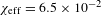
– The minimal CA (GCA: BODNER-Target without a thin gold overcoat) is
 $\unicode[STIX]{x1D712}_{\text{g}}=1.2\times 10^{-3}$
for D–T and
$\unicode[STIX]{x1D712}_{\text{g}}=1.2\times 10^{-3}$
for D–T and
 $\unicode[STIX]{x1D712}_{\text{g}}=1.08\times 10^{-3}$
for
$\unicode[STIX]{x1D712}_{\text{g}}=1.08\times 10^{-3}$
for
 $\text{D}_{2}$
. For simplicity, we take the same value
$\text{D}_{2}$
. For simplicity, we take the same value
 $\unicode[STIX]{x1D712}_{\text{g}}=10^{-3}$
for
$\unicode[STIX]{x1D712}_{\text{g}}=10^{-3}$
for
 $\text{D}_{2}$
and D–T to estimate the time
$\text{D}_{2}$
and D–T to estimate the time
 $\unicode[STIX]{x1D70F}_{\text{Form}}$
(Equation (11)).
$\unicode[STIX]{x1D70F}_{\text{Form}}$
(Equation (11)).
– The maximal CA (ThCA: BODNER-Target with a thin gold overcoat) is equal to
 $\unicode[STIX]{x1D712}_{\text{eff}}\sim 6.5\times 10^{-2}$
(
$\unicode[STIX]{x1D712}_{\text{eff}}\sim 6.5\times 10^{-2}$
(
 $\text{D}_{2}$
/D–T) and shows a significant drop in the fuel freezing time during FST layering (Table 5).
$\text{D}_{2}$
/D–T) and shows a significant drop in the fuel freezing time during FST layering (Table 5).
The BODNER-Target layering time.

Analyzing the filling stage for the BODNER-Target[Reference Ito, Nagai, Norimatsu, Nikitenko, Tolokonnikov, Koresheva, Fujimura, Azechi and Mima8] we considered three different materials for the shell: polyimide, polystyrene and glow-discharged polymer. However, when analyzing the layering stage, the necessary set of shell material parameters is available only for polystyrene (PS)[22]. For this reason, we computed the FST layering time for two options: ‘PS –
 $\text{D}_{2}$
’ and ‘PS – D–T’. In the case of a porous layer, the effective conductivity could be obtained from the Clausius–Mossotti equation[Reference Aleksandrova, Belolipetskiy, Chtcherbakov, Kalabuhov, Koresheva, Koshelev, Kutergin, Nikitenko, Osipov, Panina, Safronov, Timasheva, Timofeev, Usachev, Tolley, Edwards and Spindloe21]. As for the temperature of target entry to the LC,
$\text{D}_{2}$
’ and ‘PS – D–T’. In the case of a porous layer, the effective conductivity could be obtained from the Clausius–Mossotti equation[Reference Aleksandrova, Belolipetskiy, Chtcherbakov, Kalabuhov, Koresheva, Koshelev, Kutergin, Nikitenko, Osipov, Panina, Safronov, Timasheva, Timofeev, Usachev, Tolley, Edwards and Spindloe21]. As for the temperature of target entry to the LC,
 $T_{\text{in}}$
, we chose two values:
$T_{\text{in}}$
, we chose two values:
(a) Maximum value
 $T_{\text{in}}$
– close to the temperature
$T_{\text{S}}$
for fuel separation into the liquid and vapor (assume using shells with a high tensile strength).
$T_{\text{in}}$
– close to the temperature
$T_{\text{S}}$
for fuel separation into the liquid and vapor (assume using shells with a high tensile strength).(b) Working value
$T_{\text{in}}$
– close to the temperature
$T_{\text{d}}$
under the SC depressurization before layering (assume using shells with a weak tensile strength).


In the course of modeling, we used a simulation code for rapid fuel layering inside moving free-standing IFE targets[Reference Aleksandrova, Bazdenkov and Chtcherbakov19–Reference Aleksandrova, Belolipetskiy, Chtcherbakov, Kalabuhov, Koresheva, Koshelev, Kutergin, Nikitenko, Osipov, Panina, Safronov, Timasheva, Timofeev, Usachev, Tolley, Edwards and Spindloe21] and optimized it for the BODNER-Target computations within the FST layering method. It is based on solving the Stephen’s problem for moving boundaries between the fuel phases (gas, liquid and solid) and for a nonlinear boundary condition on the outer shell surface. Heat transport outside the target is via conduction through a small contact area. The computational tools allow one to model the layering time as a function of the target and LC parameters, as well as other experimental conditions. The obtained results are summarized in Table 5. The main conclusion is as follows – the FST layering time does not exceed 23 s for
 $\text{D}_{2}$
fuel and 30 s for D–T fuel.
$\text{D}_{2}$
fuel and 30 s for D–T fuel.
The next step is the computation of a set of optimization parameters related to the LC geometry to maintain the process of BODNER-Target fabrication by the FST layering method. Our study has shown that in the case of GCA (which is the reference point for ThCA under temperature profiling along the LC) the target can be fabricated by the FST layering method using a double-spiral LC manufactured during the experimental modeling (Table 6).
Double-spiral LC (mockup testing results).

a Note: PS shell is used in this study as a surrogate target.
The following results were obtained for two temperatures
 $T_{\text{in}}$
of target entry into the LC (compare Tables 5 and 6).
$T_{\text{in}}$
of target entry into the LC (compare Tables 5 and 6).
For
 $T_{\text{in}}\sim T_{\text{d}}$
, for both
$T_{\text{in}}\sim T_{\text{d}}$
, for both
 $\text{D}_{2}$
and D–T, the double-spiral LC specifications are those at which the TIP criterion
$\text{D}_{2}$
and D–T, the double-spiral LC specifications are those at which the TIP criterion
 $\unicode[STIX]{x1D70F}_{\text{Form}}<\unicode[STIX]{x1D70F}_{\text{rol}}$
is valid for the BODNER-Target.
$\unicode[STIX]{x1D70F}_{\text{Form}}<\unicode[STIX]{x1D70F}_{\text{rol}}$
is valid for the BODNER-Target.
For
 $T_{\text{in}}\sim T_{\text{S}}$
and
$T_{\text{in}}\sim T_{\text{S}}$
and
 $\text{D}_{2}$
fuel, the TIP criterion is valid.
$\text{D}_{2}$
fuel, the TIP criterion is valid.
For
 $T_{\text{in}}\sim T_{\text{S}}$
and D–T fuel, the TIP criterion is not valid (
$T_{\text{in}}\sim T_{\text{S}}$
and D–T fuel, the TIP criterion is not valid (
 $\unicode[STIX]{x1D70F}_{\text{Form}}=28.5$
s and
$\unicode[STIX]{x1D70F}_{\text{Form}}=28.5$
s and
 $\unicode[STIX]{x1D70F}_{\text{rol}}=23.5$
s).
$\unicode[STIX]{x1D70F}_{\text{rol}}=23.5$
s).
Nevertheless, the double-spiral LC works in this case as well because if the spiral angle varies slightly along the spiral length then one can scale down or scale up the target speed and, correspondingly, the rolling time
 $\unicode[STIX]{x1D70F}_{\text{rol}}$
. In addition, the length of Spiral 2 can be extended to
$\unicode[STIX]{x1D70F}_{\text{rol}}$
. In addition, the length of Spiral 2 can be extended to
 ${\sim}1.7$
m to meet the TIP criterion.
${\sim}1.7$
m to meet the TIP criterion.
Another option for BODNER-Targets is a three-fold-spiral LC manufactured during the experimental modeling (Table 7).
Three-fold-spiral LC (mockup testing results).

a Note: PS shell is used in this study as a surrogate target.
The computation has shown that within
 ${\sim}$
5 s after the start (which corresponds to
${\sim}$
5 s after the start (which corresponds to
 $S=0.7$
m along the spiral path), target motion proceeds with a constant velocity
$S=0.7$
m along the spiral path), target motion proceeds with a constant velocity
 $V_{\text{max}}=0.3~\text{m}/\text{s}$
. As the total length of the spiral (Specifications #1) is 9.187 m, then we have
$V_{\text{max}}=0.3~\text{m}/\text{s}$
. As the total length of the spiral (Specifications #1) is 9.187 m, then we have
 $(9.187-0.7)/0.3=28.29$
s. Thus, the total rolling time is
$(9.187-0.7)/0.3=28.29$
s. Thus, the total rolling time is
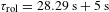 $\unicode[STIX]{x1D70F}_{\text{rol}}=28.29~\text{s}+5~\text{s}$
(elapsed time before achievement of
$\unicode[STIX]{x1D70F}_{\text{rol}}=28.29~\text{s}+5~\text{s}$
(elapsed time before achievement of
 $V_{\text{max}}$
)
$V_{\text{max}}$
)
 $=$
33.29 s, which is in good agreement with the experiment (Table 7). Thus, we can realize the rolling conditions for BODNER-Target fabrication and satisfy the TIP criterion in the case of a three-fold-spiral LC even with a certain time margin. Nevertheless, further development of computational models of the targets response during their movement in the LC is required to optimize the FST layering time (especially
$=$
33.29 s, which is in good agreement with the experiment (Table 7). Thus, we can realize the rolling conditions for BODNER-Target fabrication and satisfy the TIP criterion in the case of a three-fold-spiral LC even with a certain time margin. Nevertheless, further development of computational models of the targets response during their movement in the LC is required to optimize the FST layering time (especially
 $\unicode[STIX]{x1D70F}_{\text{Sym}}$
) and to plan experiments with different IFE targets or under special experimental conditions.
$\unicode[STIX]{x1D70F}_{\text{Sym}}$
) and to plan experiments with different IFE targets or under special experimental conditions.
For example, the proposed three-fold-spiral LC (Specifications #1, Table 7) can have a short extra spiral (Specifications #2, Table 8) so that two spirals ‘Spiral 3
 $+$
Spiral 4’ make a combined layering channel (CLC)[Reference Aleksandrova and Koresheva1], which, as a matter of fact, consists of these spirals assembled one after another: acceleration Spiral 3
$+$
Spiral 4’ make a combined layering channel (CLC)[Reference Aleksandrova and Koresheva1], which, as a matter of fact, consists of these spirals assembled one after another: acceleration Spiral 3
 $+$
deceleration Spiral 4. This allows one to reduce the target velocity at the CLC output (if needed). It takes no more than 1.5 s at
$+$
deceleration Spiral 4. This allows one to reduce the target velocity at the CLC output (if needed). It takes no more than 1.5 s at
 $\unicode[STIX]{x1D6FC}=3^{\circ }$
.
$\unicode[STIX]{x1D6FC}=3^{\circ }$
.
Combined three-fold-spiral LC.

Thus, BODNER-Targets with
 $\text{D}_{2}$
/D–T fuel can be fabricated by the FST layering method using
$\text{D}_{2}$
/D–T fuel can be fabricated by the FST layering method using
 $n$
-fold-spiral LCs at
$n$
-fold-spiral LCs at
 $n=2,3$
.
$n=2,3$
.
A few comments should be made regarding the ThCA. The GCA expansion caused by heat transfer in the case of a 0.03-
 $\unicode[STIX]{x03BC}\text{m}$
gold layer in the BODNER-Target design gives
$\unicode[STIX]{x03BC}\text{m}$
gold layer in the BODNER-Target design gives
 $\unicode[STIX]{x1D712}_{\text{eff}}=6.5\times 10^{-2}$
. For both
$\unicode[STIX]{x1D712}_{\text{eff}}=6.5\times 10^{-2}$
. For both
 $\text{D}_{2}$
and D–T fuel,
$\text{D}_{2}$
and D–T fuel,
 $\unicode[STIX]{x1D70F}_{\text{Form}}<0.5$
s (Table 5), and LC-temperature profiling becomes necessary to increase
$\unicode[STIX]{x1D70F}_{\text{Form}}<0.5$
s (Table 5), and LC-temperature profiling becomes necessary to increase
 $\unicode[STIX]{x1D70F}_{\text{Liquid}}$
and obtain a uniform layer. In this instance,
$\unicode[STIX]{x1D70F}_{\text{Liquid}}$
and obtain a uniform layer. In this instance,
 $T_{\text{in}}$
can be
$T_{\text{in}}$
can be
 ${\sim}$
21 K, as the hydrogen isotope vapor pressures near the triple point determine the minimum operating pressures (Table 3) to consider an injection filling procedure. In Ref. [Reference Ito, Nagai, Norimatsu, Nikitenko, Tolokonnikov, Koresheva, Fujimura, Azechi and Mima8], it is noted that filling of the polymer shells with a cryogenic liquid fuel is suitable for the FST method because the fusion fuel in the shell directly before the FST layering has a two-phase state ‘liquid
${\sim}$
21 K, as the hydrogen isotope vapor pressures near the triple point determine the minimum operating pressures (Table 3) to consider an injection filling procedure. In Ref. [Reference Ito, Nagai, Norimatsu, Nikitenko, Tolokonnikov, Koresheva, Fujimura, Azechi and Mima8], it is noted that filling of the polymer shells with a cryogenic liquid fuel is suitable for the FST method because the fusion fuel in the shell directly before the FST layering has a two-phase state ‘liquid
 $+$
vapor’ (Figures 2 and 3). As stated in Ref. [Reference Wittman23], future direct-drive inertial fusion cryogenic targets will be filled with D–T mixtures through fill tubes of a few tens of micrometers in diameter. A testing facility has been constructed at the Laboratory for Laser Energetics (University of Rochester, USA) to determine the temperature and pressure requirements.
$+$
vapor’ (Figures 2 and 3). As stated in Ref. [Reference Wittman23], future direct-drive inertial fusion cryogenic targets will be filled with D–T mixtures through fill tubes of a few tens of micrometers in diameter. A testing facility has been constructed at the Laboratory for Laser Energetics (University of Rochester, USA) to determine the temperature and pressure requirements.
2.3 BODNER-Target self-heating from the beta-decay of tritium
The target self-heating is a natural process driven by bulk fuel heating from the beta-decay of tritium contained in the D–T mixture. The radioactive transformation parameters have the following values: the half-life period is
 $T_{1/2}=12.33$
years and the average decay energy is 5.54 keV[Reference Souers13]. The law of radioactive transformation is quite simple:
$T_{1/2}=12.33$
years and the average decay energy is 5.54 keV[Reference Souers13]. The law of radioactive transformation is quite simple:
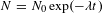 $N=N_{0}\exp (-\unicode[STIX]{x1D706}t)$
, where
$N=N_{0}\exp (-\unicode[STIX]{x1D706}t)$
, where
 $N_{0}$
is the initial number of radioactive nuclides at
$N_{0}$
is the initial number of radioactive nuclides at
 $t=0$
and
$t=0$
and
 $\unicode[STIX]{x1D706}$
is the decay constant. If in the obtained equation we substitute the half-life period
$\unicode[STIX]{x1D706}$
is the decay constant. If in the obtained equation we substitute the half-life period
 $T_{1/2}$
instead of time
$T_{1/2}$
instead of time
 $t$
, then we can find the relationship between the decay constant
$t$
, then we can find the relationship between the decay constant
 $\unicode[STIX]{x1D706}$
and the period
$\unicode[STIX]{x1D706}$
and the period
 $T_{1/2}$
. Indeed, since the following ratios are valid:
$T_{1/2}$
. Indeed, since the following ratios are valid:
 $$\begin{eqnarray}\displaystyle & & \displaystyle N(T_{1/2})=N_{0}/2,\quad N_{0}\exp (-\unicode[STIX]{x1D706}T_{1/2})=N_{0}/2\quad \text{and}\quad \nonumber\\ \displaystyle & & \displaystyle \exp (-\unicode[STIX]{x1D706}T_{1/2})=1/2,\nonumber\end{eqnarray}$$
then the decay constant is equal to
 $\unicode[STIX]{x1D706}=\ln 2/T_{1/2}$
. Subject to the obtained equality, we can rewrite the radioactive transformation law in a form suitable for estimation:
$\unicode[STIX]{x1D706}=\ln 2/T_{1/2}$
. Subject to the obtained equality, we can rewrite the radioactive transformation law in a form suitable for estimation:
 $$\begin{eqnarray}N=N_{0}\exp (-t\ln 2/T_{1/2}).\end{eqnarray}$$
Since the half-life period (12.33 years) is much longer than the FST layering time (tens of seconds),
 $N\sim N_{0}$
and the decay rate can be estimated as
$N\sim N_{0}$
and the decay rate can be estimated as
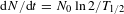 $\text{d}N/\text{d}t=N_{0}\ln 2/T_{1/2}$
. Then the average output capacity from the beta-decay
$\text{d}N/\text{d}t=N_{0}\ln 2/T_{1/2}$
. Then the average output capacity from the beta-decay
 $P_{\unicode[STIX]{x1D6FD}}$
is
$P_{\unicode[STIX]{x1D6FD}}$
is
 $$\begin{eqnarray}P_{\unicode[STIX]{x1D6FD}}=\frac{N_{0}\ln 2}{T_{1/2}}\langle E_{\text{decay}}\rangle ,\end{eqnarray}$$
where
 $E_{\text{decay}}$
is the decay energy. The average value of this energy is 5.5 keV. To estimate self-heating of the BODNER-Target, the average beta-decay capacity
$E_{\text{decay}}$
is the decay energy. The average value of this energy is 5.5 keV. To estimate self-heating of the BODNER-Target, the average beta-decay capacity
 $(P_{\unicode[STIX]{x1D6FD}}=790~\unicode[STIX]{x03BC}\text{W})$
should be compared to the minimum heat removal from the target (target without gold overcoat) due to contact conductivity between the shell wall and the LC wall (
$(P_{\unicode[STIX]{x1D6FD}}=790~\unicode[STIX]{x03BC}\text{W})$
should be compared to the minimum heat removal from the target (target without gold overcoat) due to contact conductivity between the shell wall and the LC wall (
 $Q_{\text{out}}>\text{63,000}~\unicode[STIX]{x03BC}\text{W}$
). The desired ratio
$Q_{\text{out}}>\text{63,000}~\unicode[STIX]{x03BC}\text{W}$
). The desired ratio
 $\unicode[STIX]{x1D6EF}$
will be equal to
$\unicode[STIX]{x1D6EF}$
will be equal to
 $$\begin{eqnarray}\unicode[STIX]{x1D6EF}=P_{\unicode[STIX]{x1D6FD}}/Q_{\text{out}}=0.0125.\end{eqnarray}$$
When assessing the influence of the beta-decay of tritium, we proceeded from the fact that all the generated heat assimilates. Therefore, the obtained value
 $\unicode[STIX]{x1D6EF}<1.3\%$
means that this additional heat source is negligible in the process of BODNER-Target fabrication by the FST layering method.
$\unicode[STIX]{x1D6EF}<1.3\%$
means that this additional heat source is negligible in the process of BODNER-Target fabrication by the FST layering method.
3 Practical FST-engineering for the BODNER-Target
Even a brief comparison of the computation results (Table 5) gives an idea of the strong changes in the FST layering time for different target designs. For example, a thin gold overcoat in the BODNER-Target design (
 $0.03~\unicode[STIX]{x03BC}\text{m}$
,
$0.03~\unicode[STIX]{x03BC}\text{m}$
,
 $\unicode[STIX]{x1D70C}=19.3~\text{g}/\text{cm}^{3}$
) shortens the FST layering time from 30 s to 0.5 s. Another feature is that the time for
$\unicode[STIX]{x1D70C}=19.3~\text{g}/\text{cm}^{3}$
) shortens the FST layering time from 30 s to 0.5 s. Another feature is that the time for
 $\text{D}_{2}$
/D–T fuel solidification does not represent any difficulties, but the increase in time
$\text{D}_{2}$
/D–T fuel solidification does not represent any difficulties, but the increase in time
 $\unicode[STIX]{x1D70F}_{\text{Liquid}}$
(target cooling from
$\unicode[STIX]{x1D70F}_{\text{Liquid}}$
(target cooling from
 $T_{\text{in}}$
down to
$T_{\text{in}}$
down to
 $T_{\text{TP}}$
) to reach layer uniformity on account of target rotation is one of the essential components of the FST layering method. Technologically, it provides precise control of the following input parameters: initial target temperature before FST layering
$T_{\text{TP}}$
) to reach layer uniformity on account of target rotation is one of the essential components of the FST layering method. Technologically, it provides precise control of the following input parameters: initial target temperature before FST layering
 $T_{\text{in}}$
, LC design and LC temperature (to be exact, temperature profiling along the LC).
$T_{\text{in}}$
, LC design and LC temperature (to be exact, temperature profiling along the LC).
∙ Optimization of the temperature
 $T_{\text{in}}$
. Now we pay attention to the conditions which influence the choice of
$T_{\text{in}}$
. Now we pay attention to the conditions which influence the choice of
 $T_{\text{in}}$
. In order to overcome the gravitational fuel sag to the shell bottom, the FST layering method uses a moving target that allows the difficulties inherent in the cryogenic layer formation in any fixed target to be avoided. In a batch of rolling targets (Figure 3) the time for liquid layer symmetrization,
$T_{\text{in}}$
. In order to overcome the gravitational fuel sag to the shell bottom, the FST layering method uses a moving target that allows the difficulties inherent in the cryogenic layer formation in any fixed target to be avoided. In a batch of rolling targets (Figure 3) the time for liquid layer symmetrization,
 $\unicode[STIX]{x1D70F}_{\text{Sym}}$
(defined by the target trajectory in the LC), must be less than
$\unicode[STIX]{x1D70F}_{\text{Sym}}$
(defined by the target trajectory in the LC), must be less than
 $\unicode[STIX]{x1D70F}_{\text{Liquid}}$
, or in other words,
$\unicode[STIX]{x1D70F}_{\text{Liquid}}$
, or in other words,
 $\unicode[STIX]{x1D70F}_{\text{Liquid}}$
must exceed the time for the liquid fuel to spread onto the inner shell surface to achieve the required layer uniformity (Figure 6(a)). Consider two striking examples (Figures 6(b) and 6(c)).
$\unicode[STIX]{x1D70F}_{\text{Liquid}}$
must exceed the time for the liquid fuel to spread onto the inner shell surface to achieve the required layer uniformity (Figure 6(a)). Consider two striking examples (Figures 6(b) and 6(c)).
In experiments #1 (
 $T_{\text{in}}=21$
K) and #2 (
$T_{\text{in}}=21$
K) and #2 (
 $T_{\text{in}}=15$
K, slightly above the freezing point of hydrogen (
$T_{\text{in}}=15$
K, slightly above the freezing point of hydrogen (
 $\text{H}_{2}$
)), two polystyrene shells (
$\text{H}_{2}$
)), two polystyrene shells (
 $\varnothing \sim 1$
mm) filled with gaseous
$\varnothing \sim 1$
mm) filled with gaseous
 $\text{H}_{2}$
were used up to
$\text{H}_{2}$
were used up to
 $P_{\text{f}}=765$
atm at 300 K (
$P_{\text{f}}=765$
atm at 300 K (
 $\unicode[STIX]{x1D70C}_{\text{f}}\sim 40~\text{mg}/\text{cm}^{3}$
,
$\unicode[STIX]{x1D70C}_{\text{f}}\sim 40~\text{mg}/\text{cm}^{3}$
,
 $\unicode[STIX]{x1D703}=1.33$
). The cryogenic layer thickness is
$\unicode[STIX]{x1D703}=1.33$
). The cryogenic layer thickness is
 $W\sim 90~\unicode[STIX]{x03BC}\text{m}$
at 5.5 K. The value
$W\sim 90~\unicode[STIX]{x03BC}\text{m}$
at 5.5 K. The value
 $\unicode[STIX]{x1D70F}_{\text{Sym}}$
is identical for both targets, as they have the same design and move in the same cylindrical LC (Table 9).
$\unicode[STIX]{x1D70F}_{\text{Sym}}$
is identical for both targets, as they have the same design and move in the same cylindrical LC (Table 9).
The TIP criterion (Equation (2)) is executed for both cases as well:
 $\unicode[STIX]{x1D70F}_{\text{Form}}<\unicode[STIX]{x1D70F}_{\text{Res}}$
. However,
$\unicode[STIX]{x1D70F}_{\text{Form}}<\unicode[STIX]{x1D70F}_{\text{Res}}$
. However,
 $\unicode[STIX]{x1D70F}_{\text{Liquid}}$
differs by a factor of three because of the difference in temperatures
$\unicode[STIX]{x1D70F}_{\text{Liquid}}$
differs by a factor of three because of the difference in temperatures
 $T_{\text{in}}$
(Table 9, last column). Figures 6(b) (#1) and 6(c) (#2) show the obtained results.
$T_{\text{in}}$
(Table 9, last column). Figures 6(b) (#1) and 6(c) (#2) show the obtained results.
Existence time of the liquid phase at different temperatures
 $T_{\text{in}}$
.
$T_{\text{in}}$
.

It is significant for practical FST-engineering that no symmetrization effect is observed in case #2 because the characteristic time of liquid phase existence is extremely small and makes
 $\unicode[STIX]{x1D70F}_{\text{Liquid}}=0.97$
s (
$\unicode[STIX]{x1D70F}_{\text{Liquid}}=0.97$
s (
 $T_{\text{in}}=15$
K), whereas in case #1
$T_{\text{in}}=15$
K), whereas in case #1
 $\unicode[STIX]{x1D70F}_{\text{Liquid}}=2.97$
s (
$\unicode[STIX]{x1D70F}_{\text{Liquid}}=2.97$
s (
 $T_{\text{in}}=21$
K). This indicates that
$T_{\text{in}}=21$
K). This indicates that
 $\unicode[STIX]{x1D70F}_{\text{Liquid}}$
is a key parameter, and must be sufficient for achievement of the ultimate goal as related to layer uniformity.
$\unicode[STIX]{x1D70F}_{\text{Liquid}}$
is a key parameter, and must be sufficient for achievement of the ultimate goal as related to layer uniformity.
Note that this problem is most serious at
 $\unicode[STIX]{x1D703}>1$
(Figures 9 and 10) because, compared with
$\unicode[STIX]{x1D703}>1$
(Figures 9 and 10) because, compared with
 $\unicode[STIX]{x1D703}<1$
, the large change in the amount of liquid fuel following the temperature drop might tend to induce a low-modal behavior of the liquid–vapor interface in the rolling target. Figure 6(c) shows just such ‘frozen’, extremely asymmetrical modes. For an illustration (see Figure 10(b)), we used superdurable glass shells[Reference Merkuliev, Akunets, Borisenko, Bushuev, Gromov, Dorogotovtsev, Isakov, Koresheva, Nikitenko, Tolokonnikov and Isakov16] (
$\unicode[STIX]{x1D703}<1$
, the large change in the amount of liquid fuel following the temperature drop might tend to induce a low-modal behavior of the liquid–vapor interface in the rolling target. Figure 6(c) shows just such ‘frozen’, extremely asymmetrical modes. For an illustration (see Figure 10(b)), we used superdurable glass shells[Reference Merkuliev, Akunets, Borisenko, Bushuev, Gromov, Dorogotovtsev, Isakov, Koresheva, Nikitenko, Tolokonnikov and Isakov16] (
 $\varnothing =250~\unicode[STIX]{x03BC}\text{m}$
with a thickness of 20
$\varnothing =250~\unicode[STIX]{x03BC}\text{m}$
with a thickness of 20
 $\unicode[STIX]{x03BC}\text{m}$
,
$\unicode[STIX]{x03BC}\text{m}$
,
 $\unicode[STIX]{x1D70C}_{\text{f}}=48.15~\text{mg}/\text{cm}^{3}$
,
$\unicode[STIX]{x1D70C}_{\text{f}}=48.15~\text{mg}/\text{cm}^{3}$
,
 $\unicode[STIX]{x1D703}=1.6$
) filled up to
$\unicode[STIX]{x1D703}=1.6$
) filled up to
 $P_{\text{f}}=1100$
atm (similar to the BODNER-Target) to demonstrate the change in the amount of liquid fuel upon a change in temperature.
$P_{\text{f}}=1100$
atm (similar to the BODNER-Target) to demonstrate the change in the amount of liquid fuel upon a change in temperature.
 $\text{H}_{2}$
–liquid–vapor interface behavior (meniscus) for
$\text{H}_{2}$
–liquid–vapor interface behavior (meniscus) for
 $\unicode[STIX]{x1D703}\leqslant 1$
(1, vapor; 2, liquid). In (a), with
$\unicode[STIX]{x1D703}\leqslant 1$
(1, vapor; 2, liquid). In (a), with
 $\unicode[STIX]{x1D703}=0.69$
(polystyrene shell,
$\unicode[STIX]{x1D703}=0.69$
(polystyrene shell,
 $\varnothing =940~\unicode[STIX]{x03BC}\text{m}$
, fill pressure
$\varnothing =940~\unicode[STIX]{x03BC}\text{m}$
, fill pressure
 $P_{\text{f}}=305$
atm at 300 K), the meniscus varies typically. In (b), with
$P_{\text{f}}=305$
atm at 300 K), the meniscus varies typically. In (b), with
 $\unicode[STIX]{x1D703}=0.91$
(
$\unicode[STIX]{x1D703}=0.91$
(
 $\varnothing =949~\unicode[STIX]{x03BC}\text{m}$
,
$\varnothing =949~\unicode[STIX]{x03BC}\text{m}$
,
 $P_{\text{f}}=445$
atm), near the critical density for
$P_{\text{f}}=445$
atm), near the critical density for
 $\text{H}_{2}$
, the meniscus varies greatly, from strongly concave downwards at
$\text{H}_{2}$
, the meniscus varies greatly, from strongly concave downwards at
 $T=14$
K to almost flat at
$T=14$
K to almost flat at
 $T=33$
K (a flat meniscus indicates the same material properties on both sides of the meniscus when approaching the critical point).
$T=33$
K (a flat meniscus indicates the same material properties on both sides of the meniscus when approaching the critical point).

 $\text{H}_{2}$
–liquid–vapor interface behavior for
$\text{H}_{2}$
–liquid–vapor interface behavior for
 $\unicode[STIX]{x1D703}>1$
(1, vapor; 2, liquid). (a)
$\unicode[STIX]{x1D703}>1$
(1, vapor; 2, liquid). (a)
 $\unicode[STIX]{x1D703}=1.32$
(polystyrene shell,
$\unicode[STIX]{x1D703}=1.32$
(polystyrene shell,
 $\varnothing =980~\unicode[STIX]{x03BC}\text{m}$
,
$\varnothing =980~\unicode[STIX]{x03BC}\text{m}$
,
 $P_{\text{f}}=765$
atm); (b)
$P_{\text{f}}=765$
atm); (b)
 $\unicode[STIX]{x1D703}=1.6$
(superdurable glass shell,
$\unicode[STIX]{x1D703}=1.6$
(superdurable glass shell,
 $\varnothing =250~\unicode[STIX]{x03BC}\text{m}$
,
$\varnothing =250~\unicode[STIX]{x03BC}\text{m}$
,
 $P_{\text{f}}=1100$
atm).
$P_{\text{f}}=1100$
atm).

In practice, it is known that such a low-modal perturbation would rapidly damp out in the liquid, but considering that
 $\unicode[STIX]{x1D70F}_{\text{Liquid}}$
can be sufficiently small (Table 5), it is necessary to use other means of protection. An actual route to providing acceptable layer uniformity is using different LC geometries to optimize two major factors ‘LC design and LC temperature’. The order of efficiency rating is as follows: cylindrical LCs, then
$\unicode[STIX]{x1D70F}_{\text{Liquid}}$
can be sufficiently small (Table 5), it is necessary to use other means of protection. An actual route to providing acceptable layer uniformity is using different LC geometries to optimize two major factors ‘LC design and LC temperature’. The order of efficiency rating is as follows: cylindrical LCs, then
 $n$
-fold-spiral LCs (
$n$
-fold-spiral LCs (
 $n=1,2,3$
), and finally LCs of more complex geometry (e.g., a conic spiral LC).
$n=1,2,3$
), and finally LCs of more complex geometry (e.g., a conic spiral LC).
∙ Optimization of the LC design and LC temperature. These parameters are the means by which it is possible to meet the goal of FST-LM creation (Figure 11(a)).
A variety of IFE target designs can be balanced by a corresponding choice of the LC design.

There exist numerous target designs supporting the various concepts for IFE power plants, and the fabrication techniques must have maximum flexibility to accommodate changes in target designs. During FST layering, the variety of target designs is balanced by a corresponding choice of LC designs. Several interchangeable LCs – cylindrical and spiral – were manufactured and tested. An interesting case is a combined layering channel (CLC), which consists of two spirals assembled one after another: acceleration Spiral 1 and deceleration Spiral 2 (panels (1) and (2) in Figure 11(d)) in order to zero the target speed at the CLC output[Reference Aleksandrova and Koresheva1]. The double-spiral LCs are our latest developments towards optimizing the FST layering process for targets with a diameter over 2 mm because they maintain the increase in time of the target residence in the LC and of fuel layer symmetrization during target rolling (Table 6). We have also started experiments with three-fold-spiral LCs. The obtained results are presented in Tables 7, 8 and Figure 11(b). Under the study, the LCs are manufactured with some variations in their parameters, such as inclination angle, total length, diameter and number of turns for each spiral in the three-fold-spiral LC. This allows a fuller understanding for developing the optimal processes for advanced fuel layering within moving free-standing targets. To make it more precise, the study basically focuses on the issue of how to integrate two major factors ‘LC design and LC temperature’ to realize successful FST layering for different target designs. The working principle of temperature profiling along the LC is illustrated in Figure 11(c). Technologically, it is possible to provide that a different number of spiral turns will stay within the same interval of the spiral height
 $\unicode[STIX]{x0394}l$
at a practically equal temperature gradient
$\unicode[STIX]{x0394}l$
at a practically equal temperature gradient
 $\unicode[STIX]{x0394}T$
. In doing so, winding of turns cannot be arbitrary (Figure 12), but has to be interfaced with the help of transition curves (TrCs) – for example, a Cornu spiral in which the curvature increases linearly with arc length[Reference Walton and Meek24, Reference Gobithaasan, Ali and Miura25].
$\unicode[STIX]{x0394}T$
. In doing so, winding of turns cannot be arbitrary (Figure 12), but has to be interfaced with the help of transition curves (TrCs) – for example, a Cornu spiral in which the curvature increases linearly with arc length[Reference Walton and Meek24, Reference Gobithaasan, Ali and Miura25].
A standard case of LC winding. The difficulty in designing TrCs arises from the need to have smooth target travel along the LC to avoid sudden changes in the acceleration.

The Cornu spiral is one of the TrCs. The underlying mathematical equation is the Fresnel integral. Using it as a transitional arch in road construction is functionally most interesting, because it gives a useful effect when the road stretch has the form of a part of the Cornu spiral – the car steering at turns works without breaks. Such a bend of the road allows one to implement a turn without an essential reduction of the speed. For FST-LM, design of the TrCs is a special task when constructing the LC. The following TrCs can be considered as well: cubic parabola, cardioid and Vienna arch. Successful operation of TrCs depends on detailed accounting of the LC parameters, and on the existence of a reliable database of the target material properties at room and cryogenic temperatures.
4 Concluding remarks
The LPI long-term research effort results in creation of a unique technology for advanced fuel layering within moving free-standing targets according to the ‘layering
 $+$
delivery’ scheme to produce targets for high-repetition-rate laser facilities. In this article, original results of modeling the
$+$
delivery’ scheme to produce targets for high-repetition-rate laser facilities. In this article, original results of modeling the
 $\text{D}_{2}$
/D–T layering time for a well-known target design were presented. We studied the possibility of fabricating BODNER-Targets (Figure 1) by the FST layering method (Figures 2 and 3). Our analysis has shown the following.
$\text{D}_{2}$
/D–T layering time for a well-known target design were presented. We studied the possibility of fabricating BODNER-Targets (Figure 1) by the FST layering method (Figures 2 and 3). Our analysis has shown the following.
– The total FST layering time does not exceed 23 s for
 $\text{D}_{2}$
fuel and 30 s for D–T fuel. This is a necessary condition for mass manufacturing of BODNER-Targets whilst minimizing the tritium inventory, which is one of the most important safety objectives.
$\text{D}_{2}$
fuel and 30 s for D–T fuel. This is a necessary condition for mass manufacturing of BODNER-Targets whilst minimizing the tritium inventory, which is one of the most important safety objectives.
– Dynamical layer symmetrization allows one to obtain a smoothly layered fuel for a time of about 80% of the total layering time. Nevertheless, the time for liquid fuel spreading on the interior of spherical shells can be reduced due to valid-velocity-range calculations with the aim of placing the target on the optimal trajectory for each proposed geometry of the LC. Development of state-of-the-art computational models for the target response during its motion in the LC becomes an important factor in determining spreading time during FST layering.
– The influence of the additional heat source (beta-decay of tritium) is negligible, and it should not be taken into account in BODNER-Target fabrication by the FST method.
– A foam layer has little effect on the FST layering time if the pore concentration is large (80% and more), which is quite true for the BODNER-Target design (Figure 1).
– A foam layer has little effect on the layer uniformity because the BODNER-Target includes a spherical uniform layer of pure D–T (190-
 $\unicode[STIX]{x03BC}\text{m}$
thickness) over the CH foam layer (Figure 1).
$\unicode[STIX]{x03BC}\text{m}$
thickness) over the CH foam layer (Figure 1).
– A foam layer stimulates the formation of multiple crystals of different orientations to obtain ultrafine fuel layers, thus avoiding the formation of coarse-grained crystalline structures and single-crystal-like layers. It is promising for FST layering, but it is a problem for the beta-layering method.
– Delicate metal overcoats of different configuration and composition are related to advanced developments in the area of IFE target filling and layering. The first efficient results obtained at LPI in this area are presented in Ref. [Reference Aleksandrova, Bazdenkov, Chtcherbakov, Gromov, Koresheva, Koshelev, Osipov and Yaguzinskiy20], in which we have deposited Pd (150 Å thick, 1 Å
 $=$
0.1 nm) and Pt/Pd (200 Å thick) on CH shells, filled these shells with fuel, and then formed ultrafine cryogenic layers inside them by the FST layering method.
$=$
0.1 nm) and Pt/Pd (200 Å thick) on CH shells, filled these shells with fuel, and then formed ultrafine cryogenic layers inside them by the FST layering method.
– BODNER-Targets with
 $\text{D}_{2}$
/D–T fuel can be fabricated by the FST layering method using
$\text{D}_{2}$
/D–T fuel can be fabricated by the FST layering method using
 $n$
-fold-spiral LCs at
$n$
-fold-spiral LCs at
 $n=2,3$
. We highlight that at present only curved LCs in a specialized geometry (including a conic spiral as well) and moving targets have been successfully used to develop an FST-LM with repeatable operation, which works with a target batch moving along the LC.
$n=2,3$
. We highlight that at present only curved LCs in a specialized geometry (including a conic spiral as well) and moving targets have been successfully used to develop an FST-LM with repeatable operation, which works with a target batch moving along the LC.
– Periodic mechanical disturbances applied to the target (vibrations in the range of 5–10 kHz) are a further option in fuel structurization during cryogenic layer freezing[Reference Aleksandrova and Koresheva1] to accomplish specific technological tasks for further optimization of the FST layering method for BODNER-Targets. Therefore, we plan experiments using a classical FST-LM combined with a special vibrator to launch high-frequency waves in the top part of the LC, which will in turn work as a wave guide, maintaining a vibration loading on the moving targets during their layering[Reference Aleksandrova, Akunets, Koresheva, Koshelev and Timasheva5].
Here several remarks should be made concerning the fuel structure. As shown in Refs. [Reference Aleksandrova, Belolipetskiy, Koresheva and Tolokonnikov3, Reference Aleksandrova, Koresheva, Ospov, Timasheva, Tolokonnikov, Panina, Belolipetskiy and Yaguzinskiy4], any considerable anisotropy
 $\unicode[STIX]{x1D709}$
of
$\unicode[STIX]{x1D709}$
of
 $\text{H}_{2}$
and
$\text{H}_{2}$
and
 $\text{D}_{2}$
results in the layer degrading due to roughening of the layer surface before the target reaches the chamber center. It can also result in a dependence of the shock velocity on the grain orientation. Taking into account that
$\text{D}_{2}$
results in the layer degrading due to roughening of the layer surface before the target reaches the chamber center. It can also result in a dependence of the shock velocity on the grain orientation. Taking into account that
 $\unicode[STIX]{x1D709}$
is 20% for longitudinal sound and 33% for transverse sound[Reference Wanner and Meyer12], the formation of isotropic fuel is of vital importance. In this context, the FST layering method is a valuable tool to meet the goal in the BODNER-Target for study of laser direct drive using isotropic hydrogen fuel in target compression experiments when the wave front has to be extremely smooth to avoid Rayleigh–Taylor instabilities caused by perturbations due to the grain structure. For comparison, hydrogen fuel with a different ordering of the layer structure can be fabricated as well. Below we list possible research fields using the FST layering method.
$\unicode[STIX]{x1D709}$
is 20% for longitudinal sound and 33% for transverse sound[Reference Wanner and Meyer12], the formation of isotropic fuel is of vital importance. In this context, the FST layering method is a valuable tool to meet the goal in the BODNER-Target for study of laser direct drive using isotropic hydrogen fuel in target compression experiments when the wave front has to be extremely smooth to avoid Rayleigh–Taylor instabilities caused by perturbations due to the grain structure. For comparison, hydrogen fuel with a different ordering of the layer structure can be fabricated as well. Below we list possible research fields using the FST layering method.
– Rapid FST layering (
 ${<}$
30 s) allows one to obtain isotropic ultrafine solid layers from the hydrogen isotopes in a form that meets the requirements of implosion physics. As noted above, the FST layering method is also very promising for obtaining such layers from D–T mixture, because
${<}$
30 s) allows one to obtain isotropic ultrafine solid layers from the hydrogen isotopes in a form that meets the requirements of implosion physics. As noted above, the FST layering method is also very promising for obtaining such layers from D–T mixture, because
 $\text{T}_{2}$
(
$\text{T}_{2}$
(
 $\unicode[STIX]{x1D702}=25\%$
) is considered as a high-melting-point additive to the fuel content (25% of
$\unicode[STIX]{x1D702}=25\%$
) is considered as a high-melting-point additive to the fuel content (25% of
 $\text{D}_{2}$
, 50% of D–T, and 25% of
$\text{D}_{2}$
, 50% of D–T, and 25% of
 $\text{T}_{2}$
). Additives keep the grain size stable, and hence maintain the thermal and mechanical stability of a layer as a whole. Such layers are referred to as layers with self-inherent survival features, which are of critical importance for finished target delivery into the IFE reaction chamber. This allows one to propose a new option for IFE target delivery: the target is formed in the FST-LM at
$\text{T}_{2}$
). Additives keep the grain size stable, and hence maintain the thermal and mechanical stability of a layer as a whole. Such layers are referred to as layers with self-inherent survival features, which are of critical importance for finished target delivery into the IFE reaction chamber. This allows one to propose a new option for IFE target delivery: the target is formed in the FST-LM at
 $T_{0}\sim 5$
K and then its temperature rises to 18.3 K during its delivery (
$T_{0}\sim 5$
K and then its temperature rises to 18.3 K during its delivery (
 $T_{0}$
can be any value from the interval
$T_{0}$
can be any value from the interval
 $T_{0}<18$
K, depending on the IFE chamber design).
$T_{0}<18$
K, depending on the IFE chamber design).
– Considering that during FST layering the target transport is target injection, the idea of preparing a liquid layer by first making a uniform solid layer and then melting it during free-fall (after target injection to the reaction chamber) looks promising for the fabrication of isotropic liquid fuel as well. This approach can be used in preparing a so-called critical target when the fill density in the shell is close to the critical fuel density[Reference Aleksandrova, Koresheva, Ospov, Timasheva, Tolokonnikov, Panina, Belolipetskiy and Yaguzinskiy4].
– Besides IFE advantages, several fundamental challenges such as compression experiments with laser-driven targets to investigate the matter equation of state (EOS) need to be addressed. The FST layering method can fabricate special research targets with a fuel state characterized by a different micro-structural length or grain size[Reference Aleksandrova, Koresheva, Ospov, Timasheva, Tolokonnikov, Panina, Belolipetskiy and Yaguzinskiy4]. Using these targets, as well as the critical and liquid targets under extreme conditions of high temperature and pressure, is of specific interest for EOS studies.
Thus, in IFE usage, fuel layering within free-standing and line-moving targets is a credible pathway to reliable, consistent, and economical target supply. Our latest effort, and most successful effort so far, underlies future research on the creation of the FST-LM as a means for a steady-state target-producing device, which is compatible with a noncontact schedule of target delivery to the reaction chamber[Reference Olson, Leeper, Yi, Kline, Zylstra, Peterson, Shah, Braun, Biener, Kozioziemski, Sater, Biener, Hamza, Nikroo, Berzak Hopkins, Ho, LePape and Meezan9]. Multiple target protection methods, including outer protective cryogenic layers, metal coatings of different configurations and compositions, nano-coatings for specific applications, co-injection of a special protective cover ahead of the target, etc. were analyzed in Ref. [Reference Aleksandrova and Koresheva26].
The IFE targets with ultrafine cryogenic layers[Reference Aleksandrova, Akunets, Koresheva, Kuteev and Nikitenko27] offer the prospect of using an isotropic fuel structure for plasma generation with an intensive thermonuclear reaction. Such targets for application in high-repetition-rate laser facilities allow one to test reactor-scaled technologies and identify key issues that need to be considered for the commercialization of IFE.
Acknowledgements
This work was supported by the International Atomic Energy Agency under Research Contract No. 20344 and by the Russian Government in the frame of the State Task Program.


 Open access