


Introduction
Recently, self-oscillating active integrated antennas (SOAIAs) have attracted considerable attention in the fields of wireless power transfer (WPT), radio-frequency identification systems (RFID), and wireless charging applications [Reference Kumari, Basu and Koul1–Reference Moitreya, Biswas and Akhtar3]. A key approach to realizing SOAIAs is the direct integration of active components, like transistors, with the passive radiator [Reference Kumari, Basu and Koul1–Reference Moitreya, Biswas and Akhtar3]. This integration enables the SOAIA to convert DC power directly into electromagnetic waves, thereby eliminating the need for an external oscillator [Reference Chu, Chen, Tsai and Ma4]. The result is a more compact, efficient, and simplified system. The antenna structure itself serves a dual purpose: it acts as a radiating element, transmitting the generated signal, and simultaneously forms a crucial part of the oscillating circuit. This dual functionality not only reduces the overall size and complexity of the system but also enhances its performance by ensuring precise and stable oscillation.
In the literature, several methodologies have been proposed for developing self-oscillating active integrated antennas. These include packaged cavity designs [Reference Giuppi, Georgiadis, Collado and Bozzi5], phase-locked loop (PLL) implementations [Reference Andrews and Hall6], cross-coupled oscillator configurations [Reference Amiri, Masoumi and Shahabadi7, Reference Tsai, Chu and Tzyh-Ghuang8], various reconfigurable methods [Reference Cheng-Hsun and Tzyh-Ghuang9–Reference Singh, Basu and Koul12], injection-locking networks [Reference Kai, Hummer and Klein13–Reference Ip and George15], and feedback loop strategies [Reference Mueller, Lee, Romanofsky, Kory, Lambert, Van and Miranda16, Reference Rakhi, Basu and Koul17], among others. For instance, in [Reference Giuppi, Georgiadis, Collado and Bozzi5], a compact and tunable antenna oscillator is introduced, which includes a patch antenna with an SIW cavity resonator, operating in the X-band with a frequency tuning capability from 11.87 GHz to 12.36 GHz. As reported in [Reference Tsai, Chu and Tzyh-Ghuang8], the integration of an active patch antenna with a phase-locked loop results in reduced phase noise and stabilized 4 GHz oscillation. This technology further allows for advancements in carrier frequency control, loop modulation, and channel switching. As described in [Reference Cheng-Hsun and Tzyh-Ghuang9], two planar antennas are driven by a cross-coupled oscillator comprising two bipolar transistors. By employing a differentially symmetric design, the second harmonic in the SOAIA is suppressed, reducing phase noise. When employing reconfigurable methods, self-oscillating active integrated antennas can adjust or change their operating parameters, such as oscillation frequency and radiation pattern. In [Reference Lin and Tzyh-Ghuang10], this method is implemented by incorporating two PIN diodes into a radiator, allowing for switching between two resonant modes. Another approach described in [Reference Cheng-Hsun and Tzyh-Ghuang9], involves integrating a varactor diode with a PIN diode into a frequency-reconfigurable self-oscillating active integrated antenna, enabling tuning of the oscillation frequency across two distinct bands. As per reference [Reference Singh, Basu and Koul12], an active integrated antenna that is self-oscillating and reversible in frequency and pattern was developed by the utilization of two PIN diodes to modify the radiator structure and a varactor diode to modify the resonant modes. Using a switching network to modify the phase of two patch antennas in order to provide three distinct radiation states is an alternative way to achieve pattern reconfigurability [Reference Kai, Hummer and Klein13].
This study investigates the design, optimization, and fabrication of a compact self-oscillating active integrated antenna with a nearly 1 GHz tuning range in the X-band (8.35–9.21 GHz), focusing on achieving high output power and high effective isotropic radiated power with low phase noise. This work introduces several important improvements to extend our previous 5 GHz WLAN oscillator design [Reference El Moudden, Elhamadi, Touhami, Moldovan Et and Gligor18] to the X-band (8.35–9.21 GHz). These enhancements include the redesign and simulation of the ring antenna, with dimensions tailored for efficient operation in the X-band. This process involved careful miniaturization and layout optimization to reduce parasitic effects and preserve signal integrity at high frequencies. We also added an LsCs circuit in series with the transistor drain, choosing the component values (Ls = 1.8 nH, Cs = 0.3 pF) through small-signal admittance analysis to precisely achieve the desired oscillation frequency. To facilitate accurate measurements, an SMA port was added, and an auxiliary generator technique was used to control the frequency more precisely, whereas our previous study [Reference El Moudden, Elhamadi, Touhami, Moldovan Et and Gligor18] relied on the oscPort analysis method, which often fails to converge under strong nonlinearities or certain topologies due to its reliance on linear approximations. These limitations make it unsuitable for direct frequency optimization, especially in co-simulation scenarios where circuit and electromagnetic models are closely coupled. The auxiliary generator technique offers greater flexibility and robustness, making it particularly well suited for optimization routines by enabling automatic sweeping or fine adjustment of the generator frequency to accurately determine the oscillation frequency. In addition, this work includes Equivalent Isotropically Radiated Power (EIRP) calculation and phase noise characterization, providing a more comprehensive assessment of the oscillator’s performance. This refined approach enhances the system’s applicability for wireless communication networks, facilitating seamless deployment and scalability.
The paper is organized as follows: the section “Topology of the proposed self-oscillating active integrated antenna” details the design and optimization methodology used to develop the frequency-tunable SOAIA. The section “Co-simulation results” presents simulation results from both small- and large-signal analyses, and the section “Validation of measured performance” validates these results through experimental measurements.
Topology of the proposed self-oscillating active integrated antenna
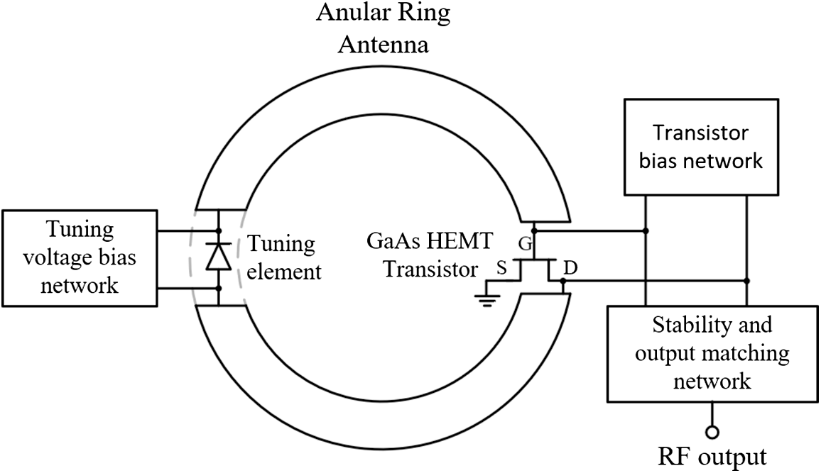
The architecture of the proposed self-oscillating active integrated antenna with extended frequency tuning is illustrated in Fig. 1.
Architecture of the proposed self-oscillating active integrated antenna.

In this proposed architecture, the feedback element is implemented by using an annular ring antenna with a C-shaped form. The transistor’s gate and drain are directly connected to this antenna. The passive antenna functions as both a radiating element and provides the necessary feedback to make the circuit oscillate. This dual function is crucial for maintaining the oscillation without the need for additional external components. For the design of the tunable SOAIA proposed, we implement a technique using an auxiliary voltage generator. This technique has proven highly effective in optimizing oscillator performance [Reference Suarez19]. In the auxiliary generator technique, an artificial generator is introduced at a specific frequency, noted as ωAG, which matches the expected oscillation frequency. This generator helps the harmonic balance simulation converge to an oscillating solution, instead of a non-oscillating one. It acts like a virtual oscillator that guides the system toward its natural behavior during the simulation. Two types of auxiliary generators can be used: voltage generators, which are connected in parallel at a circuit node, and current generators, which are connected in series within a circuit branch [Reference Suarez19]. In this work, a voltage generator is employed, connected in parallel with the transistor gate. The ideal filter avoids short-circuiting any other frequency except ωAG. In series with the voltage generator is an ideal band pass filter to avoid short-circuiting frequency components where ω ≠ ωAG.
This section is divided into three subsections: the first describes the passive antenna design, the second presents the proposed layout of the tunable self-oscillating antenna, and the third shows the electromagnetic results, including the S11 response, gain versus oscillation frequency, and radiation patterns.
Passive antenna configuration
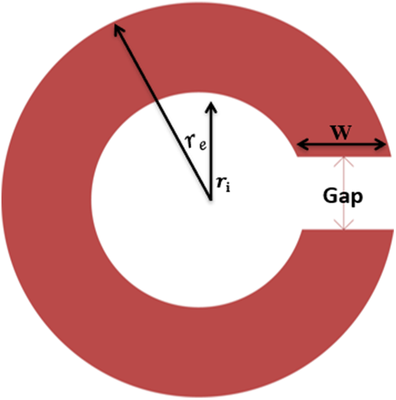
In this study, we have chosen the C-shaped antenna loop. The antenna gap was designed to match the dimensions of the transistor to ensure optimal integration. This design utilizes a RO4003C substrate, which has the specifications that include: with a substrate height of h = 0.508 mm, a dielectric constant of ε r = 3.38, and a loss tangent of tanδ = 0.0027. Table 1 provides detailed information on the antenna’s specific parameters, and Fig. 2 shows the design of this antenna.
Configuration the C-shaped antenna loop.

Passive antenna parameters

Active integrated antenna configuration
The first step after the design of the passive antenna with specific parameters in Advanced Design System (ADS) is to create a gap in the ring where both the capacitor and varactor diode will be placed. Bias lines are added to the circuit, and then perform an electromagnetic simulation using Momentum microwave, which is used for designs requiring comprehensive full-wave electromagnetic simulations, including the impact of microwave radiation effects. This will allow us to evaluate the reflection coefficient, bandwidth, radiation pattern, and gain of the passive antenna. The details of this simulation are provided in the section “Electromagnetic results.” The GaAs HEMT transistor used is an MGF4918D, biased at V GS = −0.5 V and V DS = 4.5 V. The chosen varactor diode, SMV-2019, can be adjusted from 2 to 16 V. The oscillator was built using a single dielectric substrate. Figure 3 illustrates the layout of the tunable SOAIA proposed.
Self-oscillating active integrated antenna with extended frequency tuning. (a) Equivalent circuit diagram. (b) Proposed layout.

A comparison between Fig. 3 of the present work and Fig. 7 from the previous study [Reference El Moudden, Elhamadi, Touhami, Moldovan Et and Gligor18] reveals several key modifications aimed at adapting the design for X-band operation. Notably, a filter has been incorporated at the output to suppress undesired harmonics and improve oscillator stability. Furthermore, an SMA port has been integrated to facilitate output measurement [Reference El Moudden, Elhamadi, El Bakkali and Touhami20].
Next, we continue with the co-simulation method to integrate the active elements with the passive antenna and verify the start-up conditions for the proposed tunable SOAIA. To enhance oscillator stability, An LsCs circuit is connected in series with the transistor drain. The component values (Ls = 1.8 nH, Cs = 0.3 pF) were determined through [Reference Suarez19]. This procedure begins with the selection of the biasing point, a small-signal analysis to obtain negative resistance, and the calculation of the reactive elements to set the desired oscillation frequency based on small-signal admittance analysis of the proposed tunable SOAIA at the target frequency. This circuit not only ensures stable oscillation but also accurately defines the operating frequency by filtering out undesired signals, thereby enhancing stability and minimizing frequency drift [Reference Bowick21]. The corresponding admittance analysis results, comparing the circuit’s behavior with and without the LsCs network, are presented in Fig. 6.
We present the small- and large-signal simulations for the proposed SOAIA in the subsections “Small-signal analysis for oscillation start-up” and “Large-signal verification of oscillation stability”, respectively.
Electromagnetic results
Electromagnetic simulation is a computational method employed to model and analyze the behavior of electromagnetic fields and waves across different environments and materials. In this article, we conducted an electromagnetic simulation using an electromagnetic simulator, which accounts for radiation effects. This capability allows us to visualize the radiation pattern and obtain gain values. We set the simulation frequency range from 5 GHz to 12 GHz using an adaptive sweep. Single points were added at each oscillation frequency to observe the gain at each frequency, with a total of 50 points selected. The simulation results were completed very quickly, indicating the effectiveness of the optimization method used due to the reduced simulation time. This simulation provides the reflection coefficient, bandwidth, gain, and 3D radiation pattern of a passive antenna.
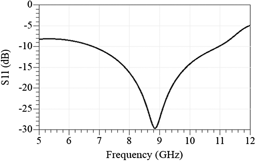
The reflection coefficient S11 was obtained at the port intended for subsequent connection to the transistor’s drain terminal. The passive antenna achieves a reflection coefficient of −29.195 dB at 8.86 GHz, with a 4 GHz bandwidth spanning from 6.8 GHz to 10.8 GHz. At 8.86 GHz, the antenna obtains a gain of 2.11 dBi. The S11 findings are displayed in Fig. 4. Figure 5(a) provides the gain versus oscillation frequency, and Fig. 5(b) presents the 3D radiation pattern. These results allowed us to achieve a gain range of 1.789–2.282 dBi within the required interval of 8.35–9.21 GHz. The gain values over the oscillation frequency range confirm the antenna’s suitability for EIRP calculation in a self-oscillating active integrated antenna, while the radiation pattern validates its radiative performance.
Reflection coefficient S11 for a passive antenna.

Passive antenna analysis: (a) Gain variation vs. oscillation frequency. (b) 3D radiation pattern.

We present specifics on the small- and large-signal simulations for the proposed SOAIA with extended frequency tuning in the subsections “Small-signal analysis for oscillation start-up” and “Large-signal verification of oscillation stability”.
Co-simulation results
The proposed SOAIA is depicted in the section “Topology of the proposed self-oscillating active integrated antenna.” To validate the overall behavior of the circuit, we performed a co-simulation method using both small- and large-signal analyses. The co-simulation method is a technique used for integrating passive and active components [Reference Ahmad, Lars and Jonsson22]. In this article, we integrate a GaAs HEMT transistor, an SMV-2019 varactor diode, and a capacitor with an annular ring antenna.
Small-signal analysis for oscillation start-up
The preliminary phase of oscillator start-up involves conducting small-signal simulations. When employing admittance analysis to guarantee the start-up of the oscillation, the total admittance of the system must have a negative real component to compensate for losses and a zero imaginary component at the resonant frequency [Reference Kurokawa23]. The condition to ensure a stable oscillation is given by the following equation [Reference Suarez19]:
 \begin{equation}\begin{gathered}
\,Y\,_T^r\,(V \cong 0,{\omega _0}^\prime ) \lt 0 \hfill \\
\,Y\,_T^r\,(V \cong 0,{\omega _0}^\prime ) = 0 \hfill \\
\frac{{\partial \left( {\,Y\,_T^r\,\,\left( {V \cong 0,{\omega _0}^\prime } \right)} \right)}}{{\partial \omega }}\, \gt 0 \hfill \\
\end{gathered} \end{equation}
\begin{equation}\begin{gathered}
\,Y\,_T^r\,(V \cong 0,{\omega _0}^\prime ) \lt 0 \hfill \\
\,Y\,_T^r\,(V \cong 0,{\omega _0}^\prime ) = 0 \hfill \\
\frac{{\partial \left( {\,Y\,_T^r\,\,\left( {V \cong 0,{\omega _0}^\prime } \right)} \right)}}{{\partial \omega }}\, \gt 0 \hfill \\
\end{gathered} \end{equation} In this context, V ≅ 0 suggests that the admittance function is analyzed under small-signal conditions, and examining condition (1) provides a stability analysis of the system. Achieving the desired resonant frequency condition  $Y\,_T^r\,(V \cong 0,{\omega _0}^\prime ) = 0$ with a positive slope $Y\,_T^r\,({\omega _0}^\prime )/\partial \omega \gt 0$ ensures stable oscillation close to ${\omega _0}^\prime $. Hence, in small-signal situations, the resonance frequency ω0′ will approximate
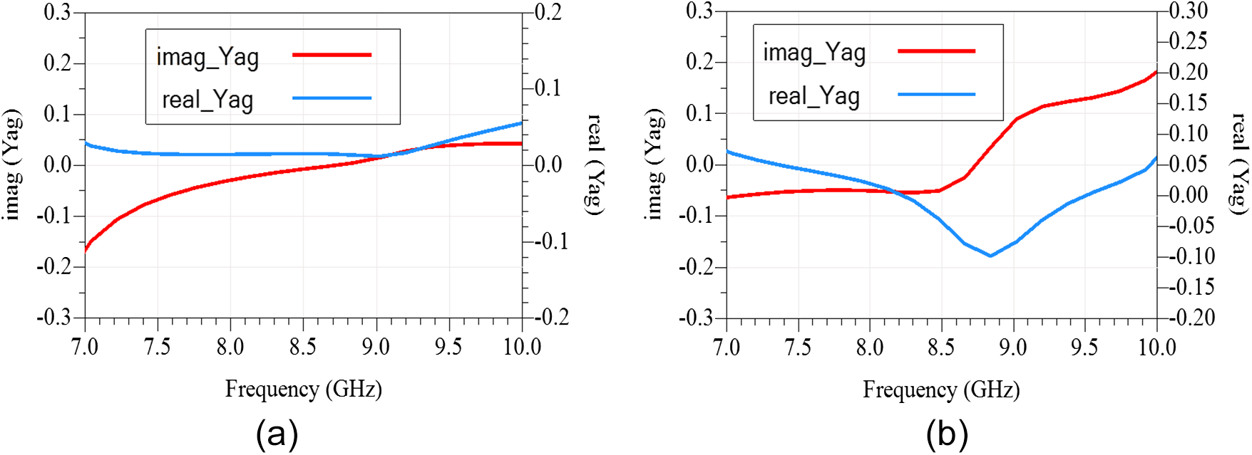
  ${\omega _0}$, although it is generally not the same [Reference Suarez19]. Figure 6 shows the result of the investigation of the small-signal admittance of the proposed SOAIA in GaAs HEMT technology. The oscillation condition was not fulfilled, as shown in Fig. 6(a). However, by adding the LsCs in series to the transistor drain with precisely fixed values of Ls = 1.8 nH and Cs = 0.3 pF, we successfully achieved the required oscillation condition, as illustrated in Fig. 6(b). The real part of the admittance takes a negative value from 8.3 GHz to 9.38 GHz, and the imaginary part equals zero at the frequency 8.68 GHz.
Small-signal admittance analysis of the proposed self-oscillating active integrated antenna with extended frequency tuning. (a) Without the stability circuit LsCs, the SOAIA start-up conditions are not fulfilled. (b) With the stability circuit LsCs, the SOAIA start-up conditions are fulfilled.

Large-signal verification of oscillation stability
After validating the oscillation start-up using small-signal analysis, this section focuses on verifying the behavior of the proposed tunable self-oscillating active integrated antenna under large-signal conditions. A large-signal stability analysis is conducted based on the periodic steady-state solution obtained through harmonic balance analysis. This approach enables a thorough evaluation of the nonlinear behavior of the circuit components to ensure that the oscillations are stable and self-sustained [Reference Suárez and Ramírez24]. By simulating the SOAIA under large-signal conditions, we were able to observe how the circuit behaves when subjected to high power levels, which is crucial for understanding its performance in practical applications.
The findings from the harmonic balance simulations are depicted in Fig. 7(a). At V var = 2 V, the oscillation frequency obtained from the simulation is 8.35 GHz, and an output power of 10.928 dBm is achieved, with the second harmonic at −10.319 dBm (16.7 GHz) and the third harmonic at −27.106 dBm (25.05 GHz). From these values, the harmonic rejection ratios are calculated as approximately 21.25 dB for the second harmonic (HRR2) and 38.03 dB for the third harmonic (HRR3). These results indicate good suppression of unwanted harmonics, confirming the oscillator’s spectral purity and linearity, which are important for minimizing interference and ensuring stable operation. As a validation of the method and the stability of the oscillator, a transient simulation was also run, and the resulting waveform instead is shown in Fig. 7(b). In the comparison between harmonic balance and transient analysis, we obtained the same frequency.
Harmonic balance and transient analysis of a tunable self-oscillating active integrated antenna proposed. (a) Power spectrum of the output power as a function of frequency at V var = 2 V. (b) Output voltage as a function of time domain.

In a voltage-controlled self-oscillating, a straightforward technique can be implemented to maximize the frequency tuning range. The bias voltage of varactor diode was varied from 2 V to 16 V. The results obtained using this method are presented in Fig. 8.
Simulation results. (a) Spectrum of the SOAIA with extended frequency tuning. (b) Oscillation frequency as a function of the varactor diode voltage, ranging from 2 V to 16 V.

Figure 8(a) consists of two parts: the first shows the output spectrum of the proposed SOAIA across the extended voltage tuning range, including the fundamental, second, and third harmonics at each tuning point, providing insight into harmonic behavior and spectral purity. The second part highlights the selected operating band, where each value of diode voltage V var corresponds to a specific oscillation frequency, demonstrating the continuous tunability of the oscillator. Figure 8(b) illustrates the variation in oscillation frequency with respect to diode voltage. This analysis resulted in an oscillator operating within a frequency range of 8.35–9.21 GHz, with output power varying from 10.928 dBm to 8.062 dBm. These results confirm the effectiveness of the proposed technique.
The phase noise of the simulated is −112.693 dBc/Hz, −132.693 dBc/Hz, and −172.731 at 100 kHz, 1 MHz, and 100 MHz, respectively. Figure 9 shows the corresponding results.
Phase noise of the self-oscillating active integrated antenna.

Validation of measured performance
The results of the simulation were shown in the preceding section. The validation of the measurement is presented in this section. The manufactured self-oscillating active integrated antenna with voltage tuning is shown in Fig. 10. Its dimensions are  $0.23 \times 0.27\,\lambda _0^2$. The experimental validation of this circuit was performed using a spectrum analyzer (Keysight E4407B, 5 KHz–26.5 GHz).
Fabricated prototype of the proposed self-oscillating active integrated antenna with extended frequency tuning.

In this article, we directly connected the RF port of the SOAIA circuit to the spectrum analyzer using an SMA cable, after calibrating the device and setting the bias voltages to V GS = −0.5 V and V DS = 4.5 V. The measurement setup is provided in Fig. 11(a). Figure 11(b) shows the experimental validation of the output power at V var = 2 V.
(a) Measurement setup. (b) Experimental validation of the output power at V var = 2 V.

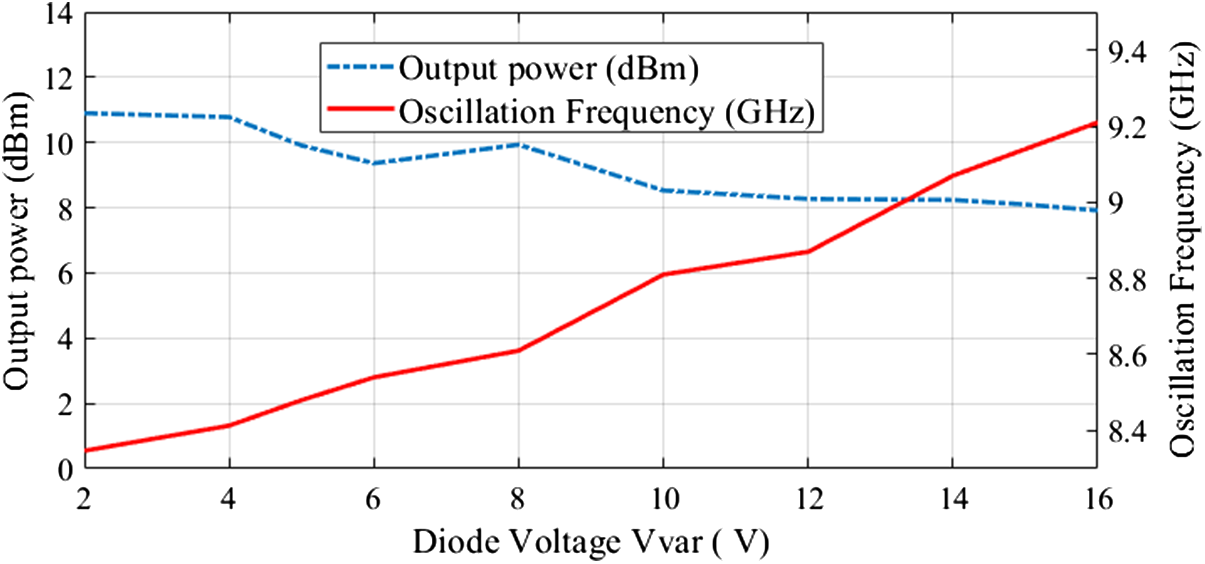
To validate the oscillation, we varied the value of diode voltage V var, sweeping it from 2 V to 16 V. This method allows us to measure the output power and oscillation frequency whenever we change the V var value. With each adjustment of the diode’s bias, the oscillation frequency shifted. Figure 12 represents the experimental validation of the output power and oscillation frequency for varying the diode voltage.
Experimental validation of the output power and oscillation frequency as a function of the diode voltage V var ranging from 2 V to 16 V.

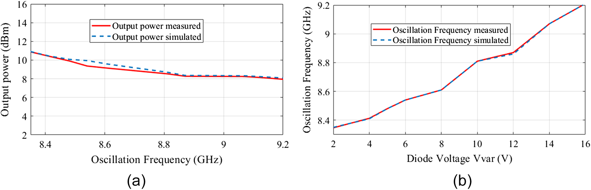
According to these results, we obtained an oscillator operating in a frequency band from 8.347 GHz to 9.210 GHz with output power ranging from 10.9 dBm to 7.916 dBm. The simulation and measured results are compared in Fig. 13, which demonstrates a good match and confirms the accuracy of our design.
Evaluation of simulated and measured results. (a) Output power as a function of oscillation frequency. (b) Oscillation frequency as a function of the diode voltage V var, ranging from 2 V to 16 V.

After simplifying the measurement of the output power of the proposed oscillator, we calculated the EIRP by adding the gain of the passive antenna to the measured output power. The formula used is given by the following equation [Reference Hasan, Nishiyama and Toyoda25]:
 \begin{equation}EIRP{\text{ }}\left( {dBm} \right){\text{ }} = {\text{ }}{P_t}\left( {dBm} \right){\text{ }} + {\text{ }}{G_{ant}}\left( {dBi} \right)\end{equation}
where Pt is the oscillation output power measured and G ant is the gain of antenna.
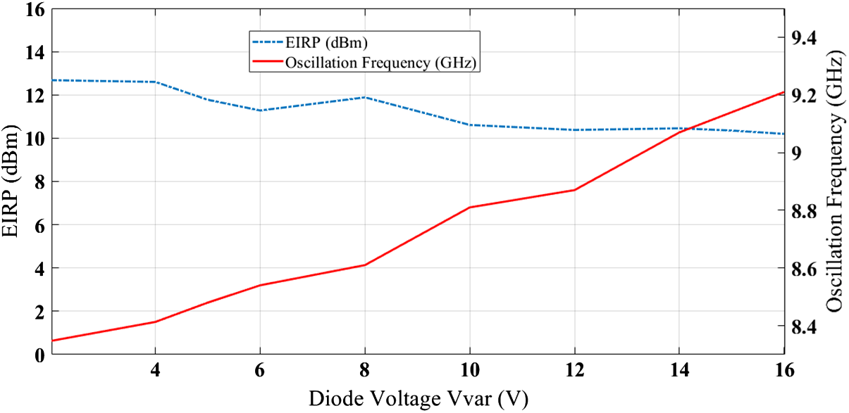
Figure 14 illustrates the EIRP and oscillation frequency results as a function of the V var. The proposed SOAIA exhibits effective isotropic radiated power ranging from 12.680 dBm to 10.198 dBm within the frequency interval of 8.35–9.21 GHz.
Experimental validation of EIRP and oscillation frequency as functions of the diode voltage V var, ranging from 2 V to 16 V.

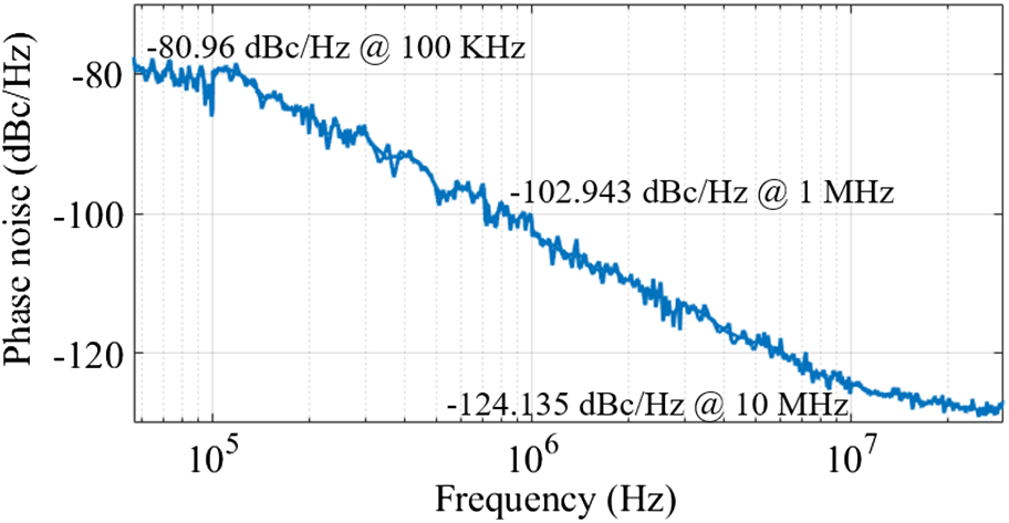
The phase noise was measured using a spectrum analyzer (Rohde & Schwarz FPL1026, 5 kHz–26.5 GHz). The measurement phase noise values are −80.96 dBc/Hz at 100 kHz, −102.943 dBc/Hz at 1 MHz, and −124.135 dBc/Hz at 10 MHz. Figure 15 presents the results of these measurements. Therefore, we can confirm that the proposed circuit produces an acceptable level of phase noise.
Experimental phase noise validation of the proposed self-oscillating active integrated antenna.

As shown in Table 2, a comprehensive performance summary of the self-oscillating AIA antenna proposed in this study is presented, compared to those documented in recent publications.
State-of-the-art review of self-oscillating active integrated antenna

The newly proposed SOAIA shows significant improvements across several performance metrics. In the study referenced as [Reference Zhang, Chen, Qi and Zhang26], a unique schematic with tunable frequency capabilities is presented. However, compared to the design we propose, several advantages of our approach stand out clearly. Firstly, our design achieves a more compact size, making it more suitable for applications where space constraints are critical. Secondly, the output power of our proposed SOAIA is significantly higher, which can enhance the performance in various practical scenarios. Thirdly, our design offers a much broader oscillation frequency range. Specifically, while the frequency range in [Reference Zhang, Chen, Qi and Zhang26] is limited to 25 MHz, our design boasts an impressive frequency range of nearly 1 GHz. Furthermore, compared with the other circuits listed in Table 2, our work consistently provides superior performance with respect to antenna gain, output power, and EIRP. The simplicity of the proposed circuit is another notable advantage, as it not only facilitates measurement and testing but also reduces overall complexity. This simplicity, combined with improved performance, makes our design a highly advantageous option for a wide range of applications. Therefore, the proposed SOAIA outperforms recent designs in terms of output power, frequency range, antenna gain, and EIRP, while being easier to measure and implement. These advantages make it a compelling choice for a variety of practical uses where performance and simplicity are paramount.
Conclusion
This study successfully developed, optimized, simulated, and evaluated a self-oscillating active integrated antenna with tunable frequency capabilities in the X-band. Performance validation was conducted through rigorous small- and large-signal analyses, supported by harmonic balance simulations in ADS. The integration of an LsCs circuit in series with the transistor drain, along with the addition of an SMA port, enhanced frequency stability and tunability while simplifying circuit measurements. Simulation results demonstrated output power levels ranging from 10.928 to 8.062 dBm, while measured output power varied between 10.90 and 7.91 dBm within the 8.35–9.21 GHz range. The strong agreement between simulated and measured results confirms the accuracy and reliability of the proposed design. The effective isotropic radiated power was observed between 12.68 and 10.198 dBm across an oscillation bandwidth of nearly 1 GHz. Additionally, phase noise measurements of −102.943 dBc/Hz at 1 MHz and −124.135 dBc/Hz at 10 MHz further validated the oscillator’s stability. This high-performance design presents promising opportunities for advancing research into tunable self-oscillating array antennas, facilitating improvements in next-generation radio communication systems and radar technologies.
Competing interests
The authors declare that they have no known competing financial interests or personal relationships that could have appeared to influence the work reported in this paper.

Hanaa El Moudden was born in Tetouan, Morocco, in 1998. He received his bachelor’s degree in 2019 and his master’s degree in Electronics and Telecommunications in 2021 from Abdelmalek Essaadi University, Tetouan, Morocco. He is currently conducting research in the Laboratory of Intelligent Systems Design (ISD) while pursuing his PhD. As part of his doctoral research, he was a researcher under an Erasmus+ scholarship with the Communications Engineering Department at the University of Cantabria, Spain. His research focuses on the design and optimization of advanced high-performance active integrated antennas, such as oscillators and amplifiers, for the analysis and design of microwave circuits.

Franco Ramírez (Senior Member, IEEE) received the Licentiate degree in electronic systems engineering from the Military School of Engineering (EMI), La Paz, Bolivia, in 2000, and the PhD degree in communications engineering from the University of Cantabria, Santander, Spain, in 2005. From 1999 to 2000, he worked at Ericsson de Bolivia Telecomunicaciones, Santa Cruz de la Sierra, Bolivia, where he was involved in projects related to Global System for Mobile Communications (GSM) and Time-Division Multiple Access (TDMA) technologies. From 2009 to 2013, he was a Research Fellow of the “Ramón y Cajal” Program, funded by the Spanish Ministry of Science and Innovation, at the Communications Engineering Department, University of Cantabria, where he is currently an Associate Professor. His research interests include phase noise, stability, and the development of nonlinear techniques for the analysis and design of autonomous microwave circuits.

Tajeddin Elhamadi was born in Alhoceima, Morocco, in 1982. He obtained his master degrees in Electronics and Telecommunications in 2013 from Abdelmalek Essaadi University. In 2017, he obtained his PhD degree in physics from Abdelmalek Essaadi University, Tetouan, Morocco. Currently, Elhamadi is a Professor at the Faculty of Sciences, Abdelmalek Essaadi University, Tetouan, Morocco. He directs his research in the information systems and telecommunications laboratory. His research work focuses on the characterization and modeling of microwave devices using neural networks, as well as the design of microwave circuits in GaAs and GaN MMIC technology. His research interests also include the optimization of planar circuits using evolutionary algorithms. In particular, the optimization of planar antennas by the genetic algorithm and the particle swarm optimization algorithm. Recently, he was introduced to the field of artificial intelligence and machine learning and their applications in the field of robotics and self-driving.

Naima Amar Touhami received DESA in Instrumentation and Electronics and PhD degree in Electronics and Telecommunication from the University of Abdelmalek Essaadi in 2002 and 2009, respectively. She received the AECID scholarship from the Spanish Ministry of Foreign Affairs (2005–2008) and participated in several research projects. She is a Professor of Electronics and Telecommunications at the University of Abdelmalek Essaadi and a member of EIRT. She has supervised master’s and bachelor’s degree students. She has more than 40 journal papers and 40 conference papers. She has participated in the organization of some conferences and events for PhD students. Her research interests include synthesis of advanced high-performance active and passive circuits such as antennas, filters, diplexer, amplifier, and mixer.


 Open access