


Introduction
Emerging wireless applications such as 5G+ communications, internet-of-things and ultra-reliable low-latency communications are driving the demand for multiband RF transceivers able to support various communication standards while effectively utilizing the electromagnetic spectrum [Reference Popovski, Trillingsgaard, Simeone and Durisi1]. To streamline their deployment, multiband RF filters with the minimal insertion loss (IL) (i.e., highest quality factor (Q)), compact size, and minimum reflection (absorptive or reflectionless) need to be incorporated in their RF front-ends to reduce the size of existing filter banks, enable future expansions to new applications and enhance their signal to noise ratio [Reference Hueber and Staszewski2, Reference Rais-Zadeh, Fox, Wentzloff and B3]. Alternative designs of absorptive or reflectionless BPFs designs have been reported to date. These include complementary diplexer architectures-based reflectionless BPFs [Reference Gómez-García, Muñoz-Ferreras and Psychogiou4, Reference Gómez-García, Muñoz-Ferreras and Psychogiou5], lossy-stub-based BPFs [Reference Wu, Li and Liu6, Reference Gómez-García, Yang and Munoz-Ferreras7], balanced-circuit-based BPFs [Reference Guyette, Hunter and Pollard8, Reference Ma, Wei, Heng, Luo, Guo and Cao9], and BPFs with even/odd-mode sub-circuit compensation [Reference Lee, Lee, Nam and Lee10]. However, none of these designs meet the stringent requirements for compactness and low IL/ high Q factor values demanded by wireless communication transceivers. They have considerable large physical size attributed to the size of their resonators with low quality factor (Q) values, typically ranging from 20 to 150.
Acoustic wave resonator (AWR)-based filters such as the ones based on surface acoustic wave (SAW), bulk acoustic wave resonator technologies are the most popular filtering architectures for portable RF transceivers due to their high Q (1,000–10,000 depending on the technology and frequency of operation) and chip-scale size [Reference Yang, Gao and Gong11, Reference Tseng, Yang, Hsiao, Chen and Wu12]. However, their transfer functions (TFs) are limited by narrow fractional bandwidth (FBW), which is typically around 0.4–0.8kt2 (kt2 is the electromechanical coupling coefficient) [Reference Gong and Piazza13].
Furthermore, most existing filters exhibit single-band TFs, leading to large-size filter banks when needing to incorporate multiband operability in the RF transceiver [Reference Tseng, Yang, Hsiao, Chen and Wu12]. While dual-band AWR-based filtering TFs have been introduced in refernce [Reference Acosta, Guerrero, Verdú and de Paco14], they are limited to only two passbands and are difficult to design. This is due to relying on AWRs with different TF characteristics, which are difficult to customize. Additionally, many of them are reflecting the unwanted RF signal energy in their stopbands which are prone to cause instabilities to their preceding/proceeding active stages. Recently, a modular AWR-based filtering concept utilizing hybridly integrated acoustic-wave lumped-element resonator (AWLR) configurations was presented. This concept enables the realization of custom quasi-elliptic RF filtering TFs with enhanced FBW [Reference Psychogiou, Gómez-García, Loeches-Sánchez and Peroulis15], continuously tunable FBW [Reference Psychogiou and Simpson16–Reference Nasser and Psychogiou19], and bandpass-to-bandstop reconfigurability [Reference Psychogiou and Simpson16, Reference Luhrs, Simpson and Psychogiou20, Reference Psychogiou, Gómez-García and Peroulis21]. Moreover, the AWLR-based concept has been further expanded to realize dual-band bandpass and bandstop TFs, as exemplified in [Reference Psychogiou, Gómez-García, Loeches-Sánchez and Peroulis15, Reference Psychogiou and Simpson16, Reference Psychogiou, Gómez-García and Peroulis18]. Despite demonstrating high levels of TF versatility (e.g., bands tuned in terms of bandwidth (BW) or are intrinsically switchable [Reference Luhrs, Simpson and Psychogiou20]), they are based on (i) multi-resonant multistage configurations that require a large number of lumped-element (LE) inverters whose loss affects the in-band IL and the out-of-band rejection or (ii) on multiple RF-switched bandpass filter (BPF) paths [Reference Zhao and Psychogiou22] whose size scales with the number of bands. In yet another approach, AWLRs based BPFs with quasi-reflectionless characteristics have been reported in references [Reference Psychogiou, Simpson and Gómez-García23, Reference Psychogiou and Gómez-García24]. However, they are limited to single-band modes of operation. Furthermore, none of the aforementioned concepts has enabled a multiband response with compact size (i.e., fewer LE components per AWLR stage) and reflectionless characteristics.
Given the limitations mentioned above, this manuscript introduces the RF design and practical development of a new class of AWLR-based multiband BPFs with reconfigurable reflection characteristics, compact physical size, improved out-of-and isolation, and lower IL when compared to previously-reported AWLR BPFs. This is achieved by using a unique multi-resonant resonator configuration that is shaped by in-parallel cascaded AWRs. A preliminary demonstration of the concept was presented in reference [Reference Nasser and Psychogiou25]. This concept is further expanded in this manuscript through additional design examples demonstrating additional TF capabilities.
Furthermore, the concept is extended to facilitate symmetric quasi-reflectionless characteristics. This is achieved by incorporating at its RF input/output two resistively terminated multi-resonant AWLR stages. The validity of this concept is demonstrated through the manufacturing and testing of dual-band and triple-band prototypes with reflective and quasi-reflective characteristics. The manuscript is organized as follows. In the “Theoretical foundations” section, the generalized filtering concept is introduced alongside its main design principles. The experimental validation of the concept is presented in the “Experimental validation” section. Finally, the main contributions of this work are discussed in the “Conclusion” section.
Theoretical foundations
Generalized multiband AWLR-based filter concept using multi-resonant stages
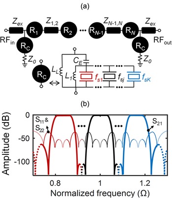
The generalized concept of the reflective multiband Nth order AWLR-based BPF concept is illustrated in Fig. 1(a). It is based on N high-Q multi-resonant bandpass-type AWLR stages (Ri) that are cascaded in-series with N-1 impedance inverters. Each multi-resonant stage comprises one lumped-inductor L0i and K distinct one-port type AWRs (represented by their Butterworth-Van-Dyke circuit model [Reference Psychogiou, Gómez-García and Peroulis26] where CMj, LMj, RMj are the motional capacitance, inductance, and resistance that resonate at the series resonance fsj, and C0j is the parasitic capacitance) whose fsj (j = 1, 2, …, K) defines the location of each passband. As such, each multi-resonant stage contributes to the filtering TF to K poles at fsj. By selecting L0i to resonate with the sum of the AWRs’ parasitic capacitances C0 =  ${{\Sigma }}_1^K$C0j at f0i (i = 1, 2, …, N) the series resonances of each AWR are decoupled from their antiresonances and create (K+1) transmission zeros (TZs). The multi-resonant stages Ri are coupled to the RF-ports through impedance inverters Zex and are cascaded using (N-1) impedance inverters (Z 1,2–ZN-1, N) to form an Nth order quasi-elliptic filtering TF shaped by K•(N)-pole and N•(K+1)-TZ, as illustrated by the conceptual response in Fig. 1(b).
Multiband quasi-elliptic AWLR-based BPFs using multi-resonant AWLR stages with reflective response characteristics: (a) Generalized circuit schematic of the reflective multiband AWLR-based BPF comprising N in-series cascaded bandpass-type multi-resonant stages (black circles) (R1, …, RN) and N-1 impedance inverters (black rectangles). Each multi-resonant stage comprises one LE inductor and K in-parallel cascaded AWRs, each with a different series resonant frequency fsK, where fsK is the center frequency of the Kth passband; (b) Conceptual S-parameters of the reflective multiband AWLR-based BPF that exhibits K bands shaped by K•(N) poles and a total of N•(K+1)•(TZs).

The Nth order multiband AWLR-based BPF can be adapted to achieve symmetric quasi-reflectionless characteristics. This is accomplished by incorporating two resistively terminated bandstop-type multi-resonant AWLR stages (RC) at the RF input/output ports of the first (R1) and last stage (RN). In this manner a symmetric quasi-reflectionless multiband TF can be created as a result of the generalized block diagram depicted in Fig. 2(a). Each RC multi-resonant stage comprises two lumped-inductors L1 and LL, one lumped-capacitor CE, and K distinct one-port type AWRs (each resonating at the series resonance fsj, j = 1, 2, …, K). The K AWRs and L1 are in-parallel cascaded and are connected in series to the CE and loaded by the inductor LL. The inductor L1 decouples the series resonances of the AWRs from their antiresonances, and together with CE and LL they create a multiband bandstop-type filtering response that is formed by K stopbands. The FBW of the K stopbands FBW is controlled by altering the values of L1, CE, and LL [see Fig. 9 for K = 2 example]. The RC stages are designed to have a complementary response to the Ri stages. When resistively terminated and connected to the input/ output of the R1 and RN, the signal reflected at the input of R1 is transmitted through RC and dissipated in the resistive termination. Similarly, the signal reflected at the output of RN is transmitted through RC and dissipated in the resistive termination.
Multiband quasi-elliptic AWLR-based BPFs using multi-resonant AWLR stages with quasi-reflectionless response characteristics: (a) Generalized circuit schematic of the quasi-reflectionless AWLR multiband BPF. The quasi-reflectionless response is obtained by connecting two resistively terminated bandstop-type multi-resonant AWLR stages (R C) at the RF input/output ports of the multiband AWLR BPF in Figure 1(a). Each RC stage comprises one LE inductor (L1) that is connected in-parallel to K AWRs. These are connected in series to a LE capacitor CE and are loaded with a LE inductor LL; (b) Conceptual S-parameters of the quasi-reflectionless multiband AWLR-based BPFs.

This allows tailoring a symmetric quasi-reflectionless Nth order multiband BPF response as depicted in the conceptual response in Fig. 2(b) and will be further developed through practical examples in the “Quasi-reflectionless multiband AWLR-based BPFs” section.
Reflective multiband AWLR-based BPF
To elucidate the operating principles of the reflective-type multiband AWLR-based BPF concept, a second-order dual-band BPF (K = 2, N = 2) example is considered in Fig. 3(a) using two commercially available SAW resonators from TST SAW with kt2 = 0.12%, fs 1 = 1033.3 MHz (LM 1 = 22.47µH, CM 1 = 1.056fF, and C0 1 = 1.142pF) and fs 2 = 1040 MHz (LM 2 = 19.42µH, CM 2 = 1.206fF, and C0 2 = 1.272pF). The filter consists of two in-series cascaded dual-band bandpass-type AWLR stages (each one is formed by two distinct AWRs resonating at fs 1 and fs 2 and one LE inductor L0i) that are interconnected through the impedance inverters Zex and Z 1,2, utilizing a total of four SAW resonators. It exhibits a quasi-elliptic TF that is shaped by two two-pole passbands and six-TZ, i.e., four-pole/six-TZ. Unlike traditional AWR-based filter designs, its FBW can be designed to be wider than the 0.4–0.8kt2 limit by only by adjusting Zex and Z 1,2. Notably, wider FBWs are obtained through increasing the values of Zex and Z 1,2, as demonstrated in the linear circuit S-parameter simulations in Fig. 4. The achievable BW ranges are Band 1: BW1 = 0.47–2.5 MHz (i.e., FBW1 = 0.38–2kt2) and Band 2: BW2 = 0.54–3.05 MHz (i.e., FBW2 = 0.43–2.44kt2).The out-of-band isolation characteristics of the multiband BPF can be reconfigured to achieve alternative isolation profiles by adjusting the location of TZs around the passbands, as illustrated in Fig. 5. These TZs can be tuned by changing f01 and f02, which are practically controlled by altering the inductance of the LE inductors L01 in stage R1 and L02 in stage R2, of the TF shown in Fig. 3(a). Additionally, the TZs can be merged by setting f01 = f02 = 1.0013fs. The resonant frequencies f0i and fsj are defined as (fs 1 = 1/2π∙[LM 1∙CM 1]1/2, fs 2 = 1/2π∙[LM 2∙CM 2]1/2, fs = [fs 1∙fs 2]1/2, C0 = C01+C02, f01 = 1/2π∙[L01∙C0]1/2 and f0 2 = 1/2π∙[L0 2∙C0]1/2).
Dual-band BPF shaped by two multi-resonant stages and exhibits a four-pole/ six-TZ transfer function: (a) Circuit schematic; (b) Simulated S-parameters using linear circuit simulations (Zex = 86 Ω, Z 1,2 = 37 Ω, f0 1 = 0.988fs, f0 2 = 1.0138fs, fs 1 is the series resonant frequency of the commercially available SAW resonator with LM 1 = 22.47µH, CM 1 = 1.056fF, and C0 1 = 1.142pF, fs2 is the series resonant frequency of the commercially available SAW resonator with LM2 = 19.42µH, CM 2 = 1.206fF, and C0 2 = 1.272pF, both SAW resonators have a kt2 = 0.12%, and fs = (fs 1∙fs 2)1/2).

Simulated S-parameters of the two-stage dual-band BPF in Figure 3(a) for alternative FBWs obtained by altering the Zex and Z 1,2 impedance values. In these examples, f0 1 = 0.988fs and f0 2 = 1.0138fs.

S-parameters of the two-stage dual-band BPF showing TZs tuning.

To demonstrate the multiband AWLR based BPF’s the performance considering practical realization effects, its TF is plotted in Fig. 6 as a function of finite QM 1, QM 2 (unloaded Q of the AWRs 1 and 2), and QLE (unloaded Q of the LEs at 1030 MHz). As observed, a finite QM mainly influences the depth of the TZs, while the out-of-band isolation levels are almost unaffected, even with a low QLE of around 50. Importantly, with low QLE = 50 the passbands’ overall effective Q (Qeff 1,2 = 4,000 and 4,100) remains as high as the AWR’s unloaded Q (QM 1,2 = 6,930 and 7,230).
Simulated S-parameters of the two-stage dual-band BPF in Figure 3(a) as a function of QM and QLE.

It should be noted that LE inductors exhibiting QLE > 100 are commercially and can be used for a practical realization [27]. The maximum achievable FBW is limited by the maximum realizable impedance inverter values of Zex and Z 1,2. For example, in Fig. 4, the maximum achievable FBW for bands 1 and 2 is 2 and 2.44kt2, respectively, when Zex = 117 Ω and Z 1,2 = 305 Ω. To realize high impedance Z = 305Ω at f = 1GHz using LE technology, the required LC equivalent of a π-network impedance inverter is L = Z/(2π·f) = 47nH and C = 1/(2π·f·Z) = 0.5pF. Achieving accurate impedance inverter values higher than 300 Ohm at 1GHz or higher frequencies on a PCB using off-the-shelf surface-mount device (SMD) LE components is challenging due to the need for lower capacitances (less than 0.5pF), which are hard to realize accurately given SMD capacitors typically have tolerances of  $ \pm $(0.05–0.1)pF [28], plus the parasitic capacitance from SMD soldering onto the PCBs is about 0.05pF.
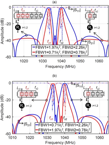
To address this constraint, the FBW of the TF can be expanded by augmenting the total capacitance C Tj = M∙CM (M is the total number of AWRs with fsj) in the corresponding circuit branch of each passband. This is accomplished by increasing the number of AWRs for each passband achieved by cascading multiple of them in parallel, as depicted in Fig. 7(a) while utilizing impedance inverters of the same characteristics. In this example, tripling the number of the AWRs (i.e., using three-resonators per fsj) widens the FBWs of bands 1 and 2 by 2.9 times compared to the standard AWLR scenario (where only one AWR is employed per fsj).
Simulated S-parameters of the two-stage dual-band BPF in Figure 3(a): (a) FBW enhancement by increasing the number of SAW resonators in the multi-resonant AWLR stage for each fsj without needing to alter the impedance inverters; (b) Independent FBW control by increasing the SAW resonators in the multi-resonant AWLR stage that corresponds to specific fsj without needing to alter the impedance inverters. In these examples, the impedance inverters are set to Zex = 62.7 Ω and Z 1,2 = 86.25 Ω.

The increase in the number of SAW resonators in AWLR stages also allows for independent control of the FBW of each passband. This is materialized by increasing the number of SAW resonators in the multi-resonant AWLR stage that control the specific band of interest as shown in Fig. 7(b) and without needing to alter the impedance inverters. In this example, by tripling the number of AWRs corresponding to band 1 (i.e., using three resonators per fs 1), the FBW of band 1 widened by 2.9 times compared to the standard AWLR case (where only one AWR is utilized per fs 1), while the FBW of band 2 remains the same as in the standard AWLR case. On the contrary, by tripling the AWRs corresponding to band 2, the FBW of band 2 is widened whereas the FBW of band 1 remains the same as in the standard AWLR case. Moreover, the multiband AWLR concept can be easily extended to accommodate additional operating bands. This is illustrated in Fig. 8, where a two-stage-based BPF is considered, comprising two bandpass-type multi-resonant AWLR stages shaped by three distinct AWRs cascaded in parallel, with the following characteristics kt2 = 0.12%, fs 1 = 1029.9 MHz (LM 1 = 22.04µH, CM 1 = 1.056fF, and C0 1 = 1.142pF), fs 2 = 1033.3 MHz (LM 2 = 22.47µH, CM 2 = 1.084fF, and C0 2 = 1.122pF) and fs 3 = 1040 MHz (LM 3 = 19.42µH, CM 3 = 1.206fF, and C0 3 = 1.272pF). The filter uses a total of six SAW resonators and exhibits three bands centered at 1029.9, 1033.36, 1040 MHz and having FBWs of 1.58, 1.39, 1.73kt2.
Simulated S-parameters for a two-stage triple-band BPF by incorporating in the multi-resonant AWLR stages (Ri) three distinct AWRs with series resonant frequencies fs 1, fs 2, and fs 3 that correspond to the center frequencies of band 1, 2, and 3 respectively.

Quasi-reflectionless multiband AWLR-based BPFs
To demonstrate the operating principles of the symmetric quasi-reflectionless multiband BPF, we first present the operating principles of the bandstop-type multi-resonant AWLR stage.
Specifically, the schematic and linear simulation of a dual-band single stage (K = 2) bandstop-type AWLR (RC) are shown in Fig. 9. The RC is shaped using two distinct AWRs – SAW resonator from TST with kt2 = 0.12%, fs 1 = 1033.3 MHz (LM 1 = 22.47µH, CM 1 = 1.056fF, and C0 1 = 1.142pF) and fs 2 = 1040 MHz (LM 2 = 19.42µH, CM 2 = 1.206fF, and C0 2 = 1.272pF)–, two LE inductors L 1 and LL and one capacitor CE. The inductor L 1 decouples the series resonances of the AWRs from their antiresonances, and together with CE and LL, they create a dual-band bandstop-type filtering response with two stopbands, as shown by the simulated results in Fig. 9. The FBW of the two stopbands can be increased by increasing the value of CE and by decreasing the values of L1, and LL. This characteristic is exploited in the quasi-reflectionless filter to control the reflection levels.
Power transmission (|S21| = |S12|) and reflection (|S11| = |S22|) responses of the bandstop-type multi-resonant AWLR stage illustrating FBW control by altering L1, CE, and LL.

In Fig. 10, a symmetric quasi-reflectionless single-stage dual-band BPF (N = 1, K = 2) is considered using the BSF stage in Fig. 9. The design process includes the following: (i) adjusting both the bandpass-type and bandstop-type stages to complement each other’s responses [see power transmission response in Fig. 10(a)] and (ii) connecting the R1 stage in the main filtering channel and incorporating two resistively terminated RC stages at the input/output of the R1, as depicted by the block diagram in Fig. 10(b). In this manner, the R1 stage determines the overall power transmission response of the symmetric quasi-reflectionless stage, while the reflected power at its stopband regions dissipates in the resistive termination of the RC stages, achieving quasi-reflectionless behavior with a maximum reflection level of −10dB, as demonstrated in the linear simulated example in Fig. 10(b). In this example, the quasi-reflectionless AWLR stage utilizes a total of six AWRs.
Power transmission (|S21| = |S12|) and reflection (|S11| = |S22|) responses of the (a) bandpass-type multi-resonant AWLR stage and its complementary bandstop-type multi-resonant AWLR stage; (b) and the quasi-reflectionless dual-band stage. Simulated S-parameters using linear circuit simulations (f0 1 = 0.988fs, f0 2 = 1.0138fs, L1 = 6.94nH, CE = 1.01pF, LL = 26.6nH).

The symmetric quasi-reflectionless multiband BPF concept can be extended to realize higher order TFs. An example of a two-stage dual-band (N = 2, K = 2) quasi-reflectionless BPF TF is shown in Fig. 11. It incorporates two in-series cascaded dual-band bandpass-type AWLR stages, R1 and R2, which are coupled through impedance inverters Zex and Z 1,2, and are connected to two resistive-terminated dual-band bandstop-type AWLR stages (RC) exhibiting complementary characteristics to R1 and R2. The two resistive-terminated RC stages are connected at the input/output of R1 and R2. The quasi-reflectionless two-stage dual-band BPF utilizes a total of eight AWRs.
Two-stage dual-band quasi-reflectionless AWLR-based BPF shaped by two multi-resonant AWLR stages and two resistively-terminated multi-resonant AWLR stages with complementary transfer function. It exhibits a four-pole/six-TZ transfer function: (a) Circuit schematic; (b) Simulated S-parameters using linear circuit simulations (Z 1,2 = 56.5 Ω, f0 1 = 0.988 fs, f0 2 = 1.0138 fs, f 1 = 1.24 fs, CE = 1.91 pF, LL = 12.14 nH).

As shown by the linear simulation in Fig. 11, the TF exhibits a symmetric quasi-reflectionless quasi-elliptic response shaped by two two-pole passbands and six-TZ, i.e., a four-pole/six-TZ configuration with passbands centred at 1033.36 and 1040 MHz, with FBWs of 0.5 and 0.4kt2, respectively. The power transmission response is determined by the main filtering channel based on the bandpass-type AWLRs R1 and R2, while the reflected power at the stopband regions is dissipated in the resistive termination of the bandstop-type stages RCs connected at the input/output side of R1 and R2, achieving a symmetric quasi-reflectionless behavior with a maximum reflection level of −10 dB. The AWLR stages used in this example are identical to those shown in Fig. 10. Furthermore, an example of a three-stage triple-band (N = 3, K = 3) quasi-reflectionless BPF TF is provided in Fig. 12, demonstrating the scalability of the concept to higher order and higher number of passbands. The TF consists of three in-series cascaded triple-band bandpass-type AWLR stages, R1, R2, and R3, which are coupled through impedance inverters Zex, Z 1,2, and Z 2,3, and connected to two resistive-terminated triple-band bandstop-type AWLR stages (RC) exhibiting complementary characteristics to R1, R2, and R3. The two resistive-terminated RC stages are connected at the input/output of R1 and R3. The quasi-reflectionless three-stage triple-band BPF utilizes a total of 15 AWRs. As it can be shown in the linear simulation in Fig. 12, the TF exhibits a symmetric quasi-reflectionless quasi-elliptic response shaped by three three-pole passbands and twelve-TZ, i.e., a nine-pole/twelve-TZ configuration with passbands centered at 1029.9, 1033.36, and 1040 MHz, having FBWs of 0.47, 0.52, and 0.4kt2, respectively. The power transmission response is determined by the main filtering channel based on the bandpass-type AWLRs R1, R2, and R3, while the reflected power at the stopband.
Three-stage triple-band quasi-reflectionless BPF shaped by three multi-resonant AWLR stages and two resistively-terminated bandstop-type multi-resonant AWLR stages. It exhibits a nine-pole/ twelve-TZ transfer function: (a) Circuit schematic; (b) Simulated S-parameters using linear circuit simulations (Z ex = 50 Ω, Z 1,2 = Z 2,3 = 52 Ω, f0 1 = 0.988 fs, f0 2 = 1.0138 fs, f 1 = 1.24 fs, CE = 1.91 pF, LL = 12.14 nH).

regions is dissipated in the resistive termination of the bandstop-type stages RCs, achieving a symmetric quasi-reflectionless characteristics with maximum reflection level of −10 dB. The multi-resonant AWLRs are based on three distinct AWRs with the following characteristics: kt2 = 0.12%, fs1 = 1029.9 MHz (LM1 = 22.04µH, CM 1 = 1.056fF, and C01 = 1.142pF), fs2 = 1033.3 MHz (LM 2 = 22.47µH, CM 2 = 1.084fF, and C0 2 = 1.122pF), and fs 3 = 1040 MHz (LM 3 = 19.42µH, CM 3 = 1.206fF, and C0 3 = 1.272pF).
Experimental validation
To experimentally validate the quasi-elliptic multiband BPF concept with reconfigurable reflection characteristics, three filtering prototypes were designed manufactured and tested. Their RF design was performed using the design guidelines in the “Theoretical foundations” section, linear and EM simulations using the software packages ADS from Keysight and Ansys from HFSS. The prototypes were implemented on a 0.813mm thick Rogers 4003C substrate. All impedance inverters were represented by their equivalent π-type first-order LE networks. Furthermore, commercially available SAW resonators from TST SAW Inc [29]. were used for the implementation of the AWLRs.
Reflective multiband AWLR-based BPFs
Two second-order reflective multiband AWLR-based BPF prototypes were designed, manufactured, and experimentally tested. The first prototype is a dual-band (i.e., N = K = 2) BPF with passbands centred at 1033.4 and 1039.9 MHz, while the second prototype is a triple-band BPF (i.e., N = 2 and K = 3) with passbands centred at 1029.9, 1033.4, and 1039.9 MHz. The layout of the dual-band prototype is illustrated in Fig. 13(a), and a photograph of the manufactured prototype is shown in Fig. 13(b) along with the utilized SMD components. As shown the dual-band BPF prototype uses a total of four AWRs.
Second-order dual-band AWLRs BPF: (a) Filter layout; (b) Photograph of the manufactured prototype; (b) RF-measured power transmission (|S21| = |S12|) and reflection (|S11| = |S22|) response of the manufactured prototype alongside its corresponding EM-simulated response using (i) single-mode (black trace), (ii) multi-mode (blue trace) SAW BVD models.

Its RF-measured response is shown in Fig. 13(c). Additionally, its corresponding EM simulated responses using the single-mode BVD model in Fig. 1(a). The presence of spurious responses near the passbands is inherent to the SAW resonator and can be represented in simulations using the multi-mode BVD model [Reference Psychogiou, Gómez-García, Loeches-Sánchez and Peroulis15]. Importantly, these spurs are unrelated to the RF filter design methodology or the proposed integration scheme. For verification purposes, the EM simulated state using the extended multi-mode BVD model is also provided in Fig. 13(c). Overall, the EM simulated state shows a good agreement with the RF measured ones. The measured RF performance exhibits the following characteristics: (i) low band: fcen = 1033.2 MHz, 3-dB BW = 0.96 MHz that corresponds to FBW = 0.78kt2, minimum in-band IL 2.4 dB that corresponds to an extracted Qeff of 6,200 and (ii) high band: fcen = 1039.9 MHz, 3-dB BW = 1.25 MHz i.e. FBW = 1kt2, IL of 1.63 dB that corresponds to an extracted Qeff of 6,700. The out-of-band isolation was measured above 24 dB over the entire stopband region.
The layout of the triple-band prototype is illustrated in Fig. 14(a), and a photograph of the manufactured prototype is shown in Fig. 14(b) along with the utilized SMD components. As seen the triple-band BPF prototype uses a total of six AWRs. Its measured response is depicted in Fig. 14(c) alongside its corresponding EM simulated states which seems in a fairly good agreement. The measured RF performance shows the following characteristics: (i) low band: fcen = 1029.83 MHz, 3-dB BW = 0.65 MHz that corresponds to FBW = 0.53kt2, minimum in-band IL 3.95 dB that corresponds to an extracted Qeff of 5,400, (ii) middle band: fcen = 1033.4 MHz, 3-dB BW = 0.6 MHz, i.e. FBW = 0.48kt2, min-IL of 3.88 dB that corresponds to an extracted Qeff of 6,000 and (iii) high band: fcen = 1039.9 MHz, 3-dB BW = 0.87 MHz, i.e. FBW = 0.7kt2, min-IL of 3-dB that corresponds to an extracted Qeff of 6,000. The out-of-band isolation was measured above 30 dB across the entire measured stopband region. Overall, the manufactured prototypes validate the proposed multiband reflective BPF concept.
Second-order triple-band AWLRs BPF: (a) Filter layout; (b) Photograph of the manufactured prototype; (c) RF-measured power transmission (|S21| = |S12|) and reflection (|S11| = |S22|) response of the manufactured prototype alongside its corresponding EM-simulated response.

Quasi-reflectionless multiband AWLRs
A two-stage dual-band (i.e., N = K = 2) quasi-reflectionless BPF prototype with passbands centred at 1033.4 and 1039.9 MHz was developed and experimentally measured. The layout and a photograph of the manufactured prototype are depicted in Fig. 15(a) and (b). The prototype utilities a total of eight AWRs. Its RF-measured performance is shown in Fig. 15(c) in addition to the corresponding EM simulated response using measured SAW resonators for comparison purposes, and they appear to be in good agreement. The measured RF response is summarized as follow: (i) in-band 1: fcen = 1033.4 MHz, 3-dB BW = 0.46 MHz (i.e., FBW = 0.38kt2), min-IL 5.45 dB corresponding to Qeff of 5,500 and (ii) in-band 2: fcen = 1039.96 MHz, 3-dB BW = 0.65 MHz (i.e. FBW = 0.52kt2), min-IL of 3.2 dB with Qeff of 6,300. The overall TF is shaped by two two-pole passbands and six-TZ, i.e., four-pole/ six-TZ, with a quasi-reflectionless behavior exhibiting a maximum reflection level of −11.5 dB. Additionally, the out-of-band isolation was measured above 40 dB throughout the entire stopband region.
Symmetric quasi-reflectionless second-order dual-band AWLR BPFL: (a) Filter layout; (b) Photograph of the manufactured prototype; (c) RF-measured power transmission and reflection response.

Comparison with state-of-the-art AWR filters
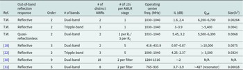
A comparison of the proposed multiband AWLR-based BPF concept with state-of-the-art AWR-based multiband filters is presented in Table 1. When compared with the concepts in references [Reference Psychogiou, Gómez-García and Peroulis18] and [Reference Zhao and Psychogiou22], the proposed concept leads to smaller size, requiring fewer LEs per stage. The reflective type BPF in this work utilizes only one LE inductor per stage, whereas in references [Reference Psychogiou, Gómez-García and Peroulis18] and [Reference Zhao and Psychogiou22], five LE components are required. The reduced number of required LEs results in a smaller filter layout. Furthermore, when compared with the filters in references [Reference Sun, Yang, Zhang, Zhang and Pang30] and [Reference Azarnaminy and Mansour31], the proposed configuration uses fewer number of distinct AWR resonators to form the passbands. Moreover, this is the only multiband AWLR BPF concept that facilitates symmetric quasi-reflectionless characteristics, compared toreferences [Reference Psychogiou, Gómez-García and Peroulis18, Reference Zhao and Psychogiou22, Reference Sun, Yang, Zhang, Zhang and Pang30], and [Reference Azarnaminy and Mansour31], which exhibit reflective type out-of-band responses.
Comparison with state-of-the-art AWR-based multiband BPFs

Conclusion
This paper presented a detailed design methodology and a practical realization scheme for miniaturized multiband AWLR-based BPFs with enhanced FBW (>0.4–0.8kt2) and reconfigurable reflection characteristics. The proposed multiband AWLR BPF concept relies on high-Q multi-resonant-AWLR bandpass-stages that are interconnected in-series using LE impedance inverters. Additionally, a method for achieving symmetric quasi-reflectionless characteristics by integrating resistively-terminated bandstop-type AWLR stages is presented. The multiband AWLR concept has been experimentally validated using three distinct filtering prototypes demonstrating dual and triple-passbands with reflective or quasi-reflectionless characteristics. These prototypes were designed, manufactured, and tested at L-band, demonstrating passbands with Qeffs > 5,000 and FBWs > 0.4kt2. The prototype with quasi-reflectionless characteristics validates the symmetric quasi-reflectionless multiband BPF concept, showing a maximum reflection level of −11.5 dB across its measured RF response.
Funding statement
This work was supported in part by Research Ireland project No. 20/RP/8334.
Competing interests
The authors report no conflict of interest.

Mohammed R. A. Nasser received the bachelor’s degree in electrical engineering from the Islamic University of Gaza, Gaza, Palestine, in 2017, and the master’s degree in electrical engineering from Akdeniz University, Antalya, Turkey, in 2020.
He is currently a Graduate Student with the Tyndall National Institute, Cork, Ireland and the School of Engineering, University College Cork, Cork. His current research interests include designing reconfigurable planar and acoustic-resonator-based RF/microwave filters. Mr. Nasser is a member of the Microwave Theory and Techniques Society.

Dimitra Psychogiou received the Dipl.-Eng. degree in Electrical and Computer Engineering from the University of Patras, Patras, Greece, in 2008, and the Ph.D. degree in Electrical Engineering from the Swiss Federal Institute of Technology (ETH), Zürich, Switzerland, in 2013. She is currently a Professor of Electrical and Electronic Engineering at the University College Cork (UCC) and the Head of the Advanced RF Technology Group at Tyndall National Institute, Cork Ireland. Prior to joining UCC, she was a Sr. Research Scientist with Purdue University, West Lafayette, IN, USA and an Assistant Professor with the University of Colorado Boulder, Boulder, CO, USA. Her current research interests include RF design and characterization of reconfigurable microwave and millimeter-wave passive components, RF-MEMS, acoustic wave resonator-based filters, tunable filter synthesis, frequency-agile antennas, and additive manufacturing technologies for 3D antenna sub-systems. Her research has been presented in more than 230 publications and has received multiple awards including the 2023 IEEE MTT-S Outstanding Young Engineer Award, the 2021 Roberto Sorrentino Prize, the SFI Research Professorship Award, the 2020 NSF CAREER Award the 2020 URSI Young Scientist Award and the Junior Faculty Outstanding Research Award from UC Boulder. Prof. Psychogiou is a Senior Member of IEEE and URSI and a member of the IEEE MTT-S Filters and Passive Components (TC-5) and Microwave Control Materials and Devices (MTT-13) committees. Furthermore, she serves on the Technical Review Board of various IEEE and EuMA conferences and journals. She is currently serving as a President for URSI Ireland, as a Co-Chair of TC-13 and the Secretary of USNC-URSI Commission D. Prof. Psychogiou is an Associate Editor of the IEEE Microwave and Wireless Components Letters and the International Journal of Microwave and Wireless Technologies. Previously, she was an Associate Editor of the IET Microwaves, Antennas and Propagation Journal.


 Open access