


1. Introduction
In recent years, the flexural pivots are increasingly utilized in the fields of precision engineering, aerospace, optical instrumentation, and gyroscope with the advantages of lightweight, infinitesimal resolution, reduced maintenance, and increased reliability [Reference Dearden, Grames, Orr, Jensen, Magleby and Howell1, Reference Shu, Liu, Kearney, Anton, Lai and Maser2]. Some applications with improved performances (i.e., robotic joint [Reference Carricato, Duffy and Parenti-Castelli3, Reference Ma, Dong, Palmer, Arreguin, Liao, Wang and Axinte4], cell manipulator [Reference Tanikawa, Ukiana, Morita, Koseki, Ohba and Fujii5], and ultra-accurate CNC [Reference Choi, Sreenivasan and Choi6]) were achieved successfully with the help of the flexural pivots. In addition, the shape memory alloy (SMA), as a novel smart material and sensitive to temperature, is extensively utilized as the actuator in the automotive [Reference Mohd Jani, Leary, Subic and Gibson7], robotic [Reference Zhou and Ma8], and biomedical fields [Reference Menciassi, Moglia, Gorini, Pernorio, Stefanini and Dario9]. However, currently, one of the most challenges for the SMA is that the back force needs to be provided to drive the SMA back to its initial position when the power is off. The conventional solution is to install a torsional spring, but this involves lots of challenges for the miniaturization. Promisingly, the flexural pivot, which realize the motion by its material deformation, is an ideal/promising mechanism to be combined with the SMA actuator for the further dimension miniaturization and performance enhancement.
Some researchers have paid much attention on the flexible pivots. Up to now, lots of work have been concentrated on the accuracy characteristics (i.e., stiffness model [Reference Zhao and Bi10], center shift [Reference Zhao, Bi and Yu11], and stress distribution [Reference Merriam, Lund and Howell12]) of the single-beam-based compliant mechanisms (i.e., generalized crossing pivot [Reference Junior and et al13], cartwheel hinge pivot [Reference Shusheng, Hongzhe and Jingjun14, Reference Pei, Yu, Zong, Bi and Su15], and butterfly flexural pivot [Reference Pei, Yu, Zong and Bi16]). Besides that, attention was also paid on establishing the theoretical models and experimental validation of the passive working flexible pivots. For example, Bi [Reference Shusheng, Hongzhe and Jingjun14] and Pei [Reference Pei, Yu, Zong, Bi and Su15] demonstrated the kinematic models of the load–displacement relationship on the single cartwheel pivot using the beam theory method and the pseudo-rigid-body method, respectively. Then, Ezekiel [Reference Merriam, Lund and Howell12] analyzed the behavior and benefits of the cartwheel pivot (i.e., enter drift, motion range, stress distribution, and stiffness), aiming to propose the flexure pivots with zero center shift characteristic. Furthermore, Kang [Reference Kang and Gweon17] researched the dynamic performance of the single cartwheel pivot by establishing the dynamic equation, then the finite element method (FEM) simulations and hammer test experiments were utilized to validate the proposed equations. Besides that, some researchers focused on the crossing pivot, which has similar characteristics to the cartwheel pivot. Awtar [Reference Awtar, Slocum and Sevincer18] stressed the characteristics (i.e., motion range, accuracy, and stiffness) of a beam-based flexure module to provide a simple yet accurate theoretical model that could parametrically predict the behavior/performance in the early stage for the designer. Pei [Reference Xu, Jingjun, Guanghua and Shusheng19] established the stiffness model of leaf-type isosceles trapezoidal flexural pivot using the pseudo-rigid-body method. Then the validation was performed by the finite element analysis method under different rotation angle inputs. Zhao [Reference Zhao, Bi and Yu20] proposed the theoretical model of a generalized cross-spring pivot about the stiffness and stress characteristics, in which the effects of different parameters on the performance variation were discussed separately for further parameter optimization. Jon [Reference Gomez, Booker and Mellor21] made a further investigation on the shape optimization of the crossing-spring pivot for minimum stress to increase the output rotation stroke. Zelenika [Reference Zelenika and De Bona22] addressed the characteristic variation of the crossing-spring pivot-based high-precision rotation mechanism under lateral loads to research the center drift. The trajectory of the geometrical center was measured and compared with the theoretical calculation under rotation inputs. However, most of the literature focused on the theoretical model establishment and characteristics reaction of the single unit flexural pivot. The practical application of the mechanisms with the flexural components, which is equally important with the academic research, is ignored, restricting the further development.
Furthermore, the SMA is an intelligent material that can change the phase of the internal crystal structure according to the external temperature [Reference Ma, Dong and Arreguin23, Reference Ma, Dong and Axinte24], enabling the stress and strain to be produced. These characters enable the SMA material to be an intelligent actuator for the challenging areas (i.e., robotics, aerospace, and biomedical). In some applications, the SMA was fabricated in plate/ribbon form for the intelligent systems, requiring the detailed constitutive model to be established to predict the reorientation of martensite variants and ferro-elasticity features. This model has the advantage to accurately predict the thermomechanical behavior of the SMA material but needs further adjustment to adapt to the mechatronic system [Reference Bodaghi, Damanpack, Aghdam and Shakeri25–Reference Bodaghi, Shakeri and Aghdam27]. As an alternative, the SMA wires have been widely used as the actuator due to its natural advantages (e.g., large mass/power ratio and good stability). Some researchers paid attention to the rotational joints that are driven by SMA wires. For example, Kolansky [Reference Kolansky, Tarazaga and Ohanian28] made a rotational joint that is controlled by two opposed SMA wires, where the high-speed rotation response (4 Hz) was obtained with the convective cooling method. Further, Guo [Reference Guo, Pan, Wee and Yu29] designed a novel compliant (torsional spring was used) differential rotation joint, which was driven by two differential SMA wires to increase the output displacement stroke. Then, Price [Reference Price, Jnifene and Naguib30] fabricated a dexterous 3-finger SMA forced robot hand, which is constituted by three rotational joints in each finger to further the research of SMA wires in the rotational joint. Besides using the SMA wire/spring as an actuator in rotational joints, some researchers focused on the SMA-driven gripper and biomimetic fish. Yan [Reference Yan, Liu, Xu and Wang31] designed a gripper actuated by a pair of differential SMA springs, and experimental tests were implemented to obtain the output displacement of the gripper tip under different external temperatures. Villanueva [Reference Villanueva, Smith and Priya32] made a biomimetic robotic jellyfish driven by SMA wires, which could actuate the bending of the steel strips fixed on the bell, and the propulsion will be produced as a result. In addition, Heinonen [Reference Heinonen, Vessonen, Klinge and Järvinen33] presented a kind of variable stiffness mechanism constituted by a steel frame and a straightened SMA wire, in which the tension of the SMA wire can be adjusted by changing the external temperature, then the stiffness of the steel frame, as a result, can be controlled. However, the torsional springs have to be used in the previously mentioned SMA-driven mechanisms, which increases the size of the mechanism and complexes the structure.
The SMA-driven rotational joint, which is composed of an SMA actuator, rotational joint, and forces back mechanism, is one of the hot topics in recent years. However, as the torsional spring or differential SMA actuators are mostly adopted to realize the reciprocating motion of the joint, it is becoming more challenging to further minimize the dimension (Fig. 1). For example, Maeno [Reference Maeno and Hino34] designed a tiny five-fingered robot hand that is driven by SMA wires with the size of about one-third of human hand. However, the working cycle is too long to be used in real applications. A two DoFs Mini Hollow joint was developed and actuated by SMA wires to reduce the dimension of the system [Reference Manfredi and Cuschieri35]. Guo [Reference Guo, Pan, Wee and Yu29] proposed a novel compliant differential SMA-driven rotational joint with a torsional spring inside to increase the response speed. As the degradation phenomenon of the shape memory effect is becoming significant when the SMA wire is over-heated or over-stretched, which will decrease the performance of the differential actuator seriously. Ashrafiuon [Reference Ashrafiuon, Eshraghi and Elahinia36] made a three-degree-of-freedom robot arm composed of three SMA-driven rotational joints. The kinematics and dynamics of the SMA wire and the robot arm were established to explore the dynamic characteristics.
Examples of the SMA-driven rotational mechanisms: a) SMA actuated artificial hand [Reference Maeno and Hino34] (the rotation of the joint is driven by the SMA wire); b) two DoFs joint that actuated by SMA wires [Reference Manfredi and Cuschieri35]; c) a novel compliant differential SMA actuator [Reference Guo, Pan, Wee and Yu29]; d) three-link SMA actuated robot arm [Reference Ashrafiuon, Eshraghi and Elahinia36].

From the structure characters of the proposed rotational joint, the combination of flexible pivots and SMA actuator has the following attributes:
-
1. The flexible pivot is a kind of mechanism that the motion is achieved by the material deformation, enabling no backlash between the adjacent components.
-
2. The SMA is a kind of material that can produce relatively large output (i.e., strain and stress) compared with their mass/volume, which is an ideal combination for developing the miniature mechanisms.
-
3. The material deformation of flexible pivot can be utilized as the restoring force for the SMA material to the initial stage (i.e., martensite structure), which simplifies the structure.
To the best knowledge of the author, little attention has been paid on combining the flexural pivot and SMA wire to develop the high-accuracy and quick-response rotational mechanism, which is highly needed for constructing the miniature robots. In this paper, a class of novel SMA-driven flexible rotational mechanisms, which adopted the flexural pivots (e.g., crossing pivot, cartwheel pivot, and butterfly pivot) as the motion unit to be combined with the SMA actuators, was proposed and fabricated to demonstrate the concept proposed in this paper. As a result, the method (i.e., combining the flexural pivot and SMA actuator) presented in this paper provides an effective way for constructing the miniature and high-performance rotational mechanisms for spherical applications (i.e., robotic joint, clutch, engine, and positioning mechanism).
The structure of the paper is organized as follows: first, a class of flexible pivots was proposed and arranged, which have the potential to be combined with the SMA material for constructing the novel rotational joint. Then, to prove the feasibility of the proposed method, the cartwheel pivot was selected as a case study to be combined with SMA wire for fabricating the prototype. After that, the kinematic model of the system was developed by establishing the model of cartwheel pivot and constitutive equations of SMA wire, which provides the advantage for designing the control algorithm of the following experiments. Next, the experiments for model validation and performance tests were conducted with the developed control system. At last, the conclusion was presented.
2. A class of rotational SMA-driven mechanisms
Some conventional rotational SMA-driven mechanisms proposed by previous researchers were arranged at first to outline the advantages of using the SMA actuators in the rotational mechanisms, especially in the rotational joint. Then, a class of novel flexural pivots, which integrates the rotational motion and torsional spring characteristics, was proposed to provide a way for developing the novel rotational joint. After that, one kind of flexural pivot (i.e., cartwheel pivot) was chosen as a case to implement the concept proposed in this paper. Further, the prototype is fabricated for demonstrating the idea presented in this paper.
2.1 Conventional rotational mechanisms
To address the research gap, a new class of SMA-driven high-speed rotational mechanisms with the flexural pivots are proposed, which can be used in the robotic joint, positioning mechanism, and clutch. More importantly, the proposed rotational tool (Fig. 2) integrates the SMA actuator and flexural pivot for the first time, which demonstrates the possibility of combining the smart actuators (i.e., SMA actuator, magnetostrictive actuator, and laser-restrictive actuator) and compliant mechanisms (i.e., flexural pivot, flexural displacement magnification mechanism, and flexural developable mechanism).
A class of rotational mechanisms constituted by different kinds of leaf-spring segments: a) single-leaf pivot segment; b) cross-leaf pivot segment; c) multileaf pivot (radial arrangement of the leaf springs) segment; d) multileaf pivot (parallel arrangement of the leaf springs) segment; e) one example for the rotational mechanism configured by multisegment leaf springs; f) one possible solution for the rotational mechanism configured by single-segment leaf spring.
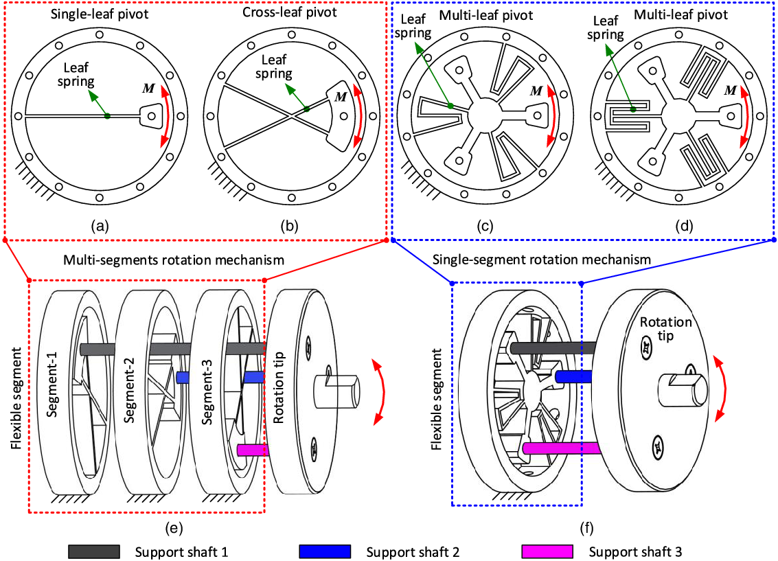
Specifically, the configuration of the rotational joint with different flexural pivots can be structured as follows:
-
1. Multisegment flexural pivots: Fig. 2 (e) presents the rotational joint with multisegment flexural pivots, where three flexural pivots are equally spaced to decrease the error and center drift. The rotation tip is fully connected with the three flexural pivots by the rigid shafts to realize the rotation accuracy under the external loads. The flexural pivots used in the example rotational joint can be in the form of single-leaf pivot (a), crossing pivot (b), butterfly pivot (c), and cartwheel pivot (d).
-
2. Single-segment flexural pivots: Fig. 2 (f) illustrates the rotational joint with single-segment flexural pivots, where only one flexural pivot can satisfy the motion requirement of the joint, but more numbers of this kind of flexural pivot segments can increase performances of rotational joint (i.e., stability, response speed, and accuracy). The flexural pivots used in single-segment flexural pivots can be in the type like multileaf pivots (c) and (d).
The multisegment and single-segment flexural pivots presented in Fig. 2 can be used as a kind of large-displacement flexural bearings individually, which some researchers have researched. But these kinds of flexural segments will be developed as a new class of actively rotational joints on special occasions (e.g., robotic, biomimetic, and aerospace) with the intelligent actuators (e.g., SMA material).
2.2 Feasibility analysis and prototype design
As the SMA wire can only provide limited stress during the temperature variation, the parameters for the flexural pivots (e.g., width, length, and thickness of the leaf spring) should be selected appropriately for obtaining the better rotation performance of theSMA wire-driven flexural rotational mechanism (SDFRM). The cartwheel pivot, which has better mechanical behaviors (e.g., large rotation stroke and small center drift), is selected to construct the SDFRM. To guide the structure of the SDFRM, the FEM simulation method is selected in this section to forecast the required external, which will be fitted with the mechanical parameters of the SMA wires (i.e., the pulley force), seen in Fig. 3.
Structure parameter illustration of the cartwheel pivot and the mechanical performance under the external loads: a) structure parameters illustration of the cartwheel pivot; b) output characteristics of cartwheel pivot under different external loads. Note: the output characteristics of an example SMA wire was illustrated in the figure (pink dotted line).
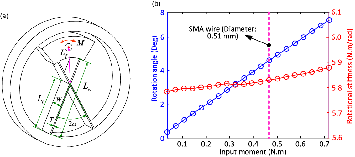
To improve the motion stability of the system, three cartwheel pivots (Fig. 3) with the identical parameters are equally spaced (120°) around the rotation center of the SDFRM. The structure of a single cartwheel pivot is shown in Fig. 3(a), which illustrates the main structural parameters for the better understanding. The external load ( $\boldsymbol{{M}}$
in Fig. 3(a)) is imposed on the upper part of the cartwheel pivot to actuate the rotation of the system. The ANSYS Workbench software is used to simulate the structure deformation of the cartwheel pivot under the given external loads. By changing the value of the external load, the output of the cartwheel pivot (i.e., rotation motion) can be obtained (seen as Fig. 3(b)), which can be used to the parameter selection of the SMA wires.
$\boldsymbol{{M}}$
in Fig. 3(a)) is imposed on the upper part of the cartwheel pivot to actuate the rotation of the system. The ANSYS Workbench software is used to simulate the structure deformation of the cartwheel pivot under the given external loads. By changing the value of the external load, the output of the cartwheel pivot (i.e., rotation motion) can be obtained (seen as Fig. 3(b)), which can be used to the parameter selection of the SMA wires.
Figure 3 (b) shows the responses of the cartwheel pivot under the different external loads. To guide the parameter selection of the SMA wires, the input–output simulation of the SDFRM is implemented with the aid of the ANSYS software. Specifically, the external load is imposed on the cartwheel pivot (i.e., varying from 0 N · m to 0.7 N · m) to obtain the rotation response of the SDFRM.
In order to achieve the reasonable rotation stroke of the cartwheel pivot for the practical application and model validation, the mechanical parameters (e.g., thickness and length of the spring leaf, angle and position of the cartwheel pivot) need to be carefully designed to match the parameter of the SMA wire (i.e., strain and stress). Based on the repeat simulation, the selected parameters of the cartwheel pivot can be seen from Table I, which are determined by considering the performance of the SMA wire. From the simulation of Fig. 3(b), the rotation stroke of the cartwheel can be around 4.5° under the given input load of around 0.47 N.m (nominated load generated by the SMA wire). Based on this result, the parameters of the cartwheel pivot are selected in this paper for the demonstration.
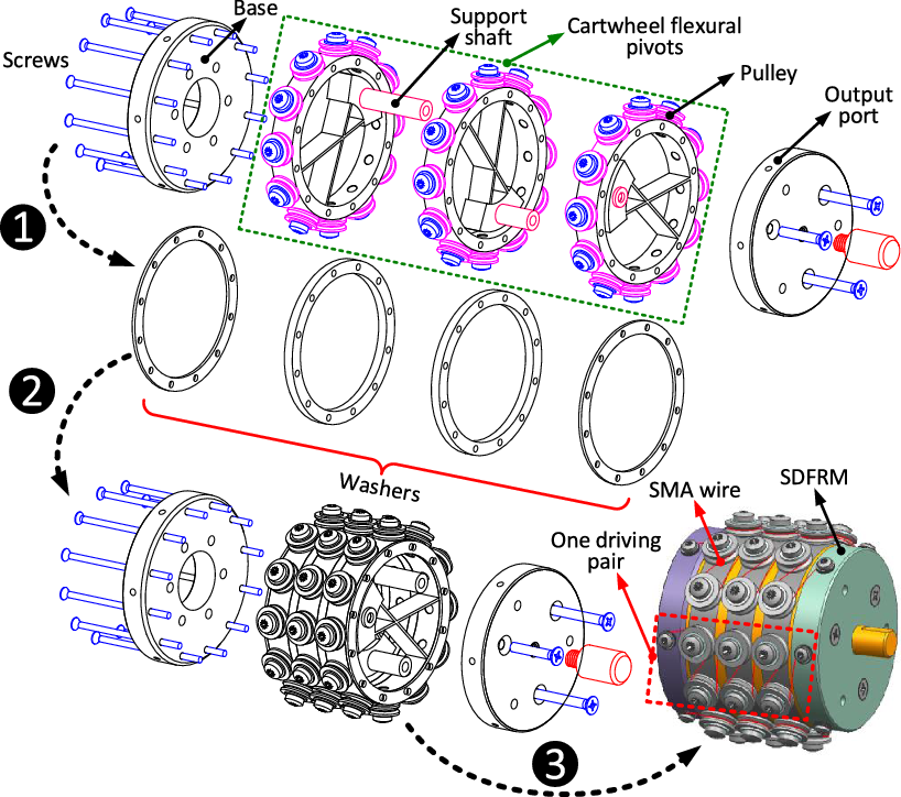
After proving the feasibility of using SMA wires to drive the rotation of the cartwheel pivot, the parameters (i.e., width, length, and angle of the leaf spring) are selected for designing the structure. The processes of the structure design for the SDFRM are shown in Fig. 4, where there are three stages for completing the whole design. In order to reduce the dimension of the SDFRM and increase the stroke, the long SMA wires are twined on the contour of the cartwheel pivots. In addition, the miniature pulleys are used to guide the shrinking of the SMA wires, which can significantly decrease the friction that caused by the relative sliding between SMA wires and support shafts. The output port, which is the rotation tip of the system, is connected to the cartwheel pivots by three support shafts and driven by several pairs of SMA wires. (Note: one end of the SMA wire is connected to the output port, while another is connected to the base of the system.)
A class of rotational mechanisms, which are constructed by the parallelly distributed flexural pivots, is arranged in the first part of this section. Furthermore, combining the rotational flexural mechanism with the SMA actuator is proposed to expand the development for further application. At last, one kind of rotational flexural pivot (i.e., cartwheel pivot), which has relatively high stiffness and small center drift, is chosen as an example for the further demonstration.
3. Model of the compliant joint
After designing the structure, the stiffness model, which is the essential characteristic of reflecting the static and dynamic performances of the SDFRM, is becoming important to design the control algorithm of the system. In addition, the number of the actuator (i.e., SMA wire) is changing to implement the rotation of the system, which provides a way to improve the performance of the system.
3.1 Load–rotation relationship of the single cartwheel pivot
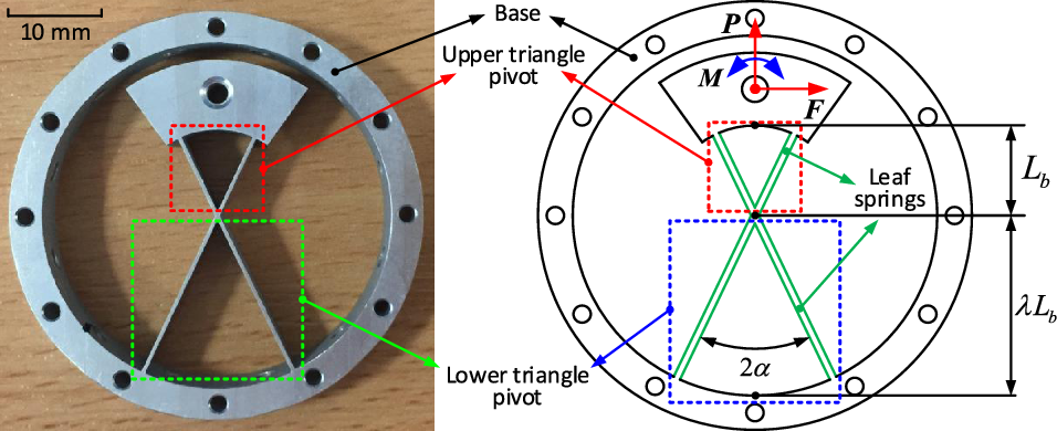
The load–relationship model of the conventional cartwheel pivot, which is constituted by two identical triangle flexural pivots, can be simplified by analyzing one triangle flexural pivot [Reference Shusheng, Hongzhe and Jingjun14]. However, for the SDFRM, all the moving parts (i.e., leaf springs and moving tip) are limited inside the ring base. To make the rotation axis of the cartwheel pivot located at the center of the ring base (enabling the three cartwheel pivots can be parallelly assembled with the same rotation center), the two triangle pivots are set unsymmetrical (i.e., lower triangle pivot is set more significant than an upper triangle, as seen in Fig. 5). The load–rotation model of the cartwheel pivot can then be used for the performance test and control algorithm design in the following.
The parameters of one cartwheel pivot.

Design process of the SDFRM. Three stages are described in designing the SDFRM: in stage 1: the three cartwheel flexural pivots, base, and output port, as well as the washers, are designed and displayed; in stage 2: the three cartwheel flexural pivots and washers are assembled as the flexible actuator for the rotational output; in stage 3: the base and output port are connected to the actuator, as well as the SMA wires are twinned around the pulleys for driving the rotation of the SDFRM. Note: the number of moving pairs can be varied for changing the performance and rotation range output for different applications.
The loads–displacement relationship of the example segment (cartwheel pivot) of SDFRM: a) the deflection of cartwheel under the external loads; b) exploded view for revealing the generated forces and displacements in critical points of leaf springs; c) forces in critical points of the rigid moving tip; d) enlarged view of the center drift; e) deformation simulation of the cartwheel with the aid of Ansys Workbench. Note: the black dashed lines of leaf springs indicate the initial position without deformation, while the solid red lines represent the deformed position under external loads.
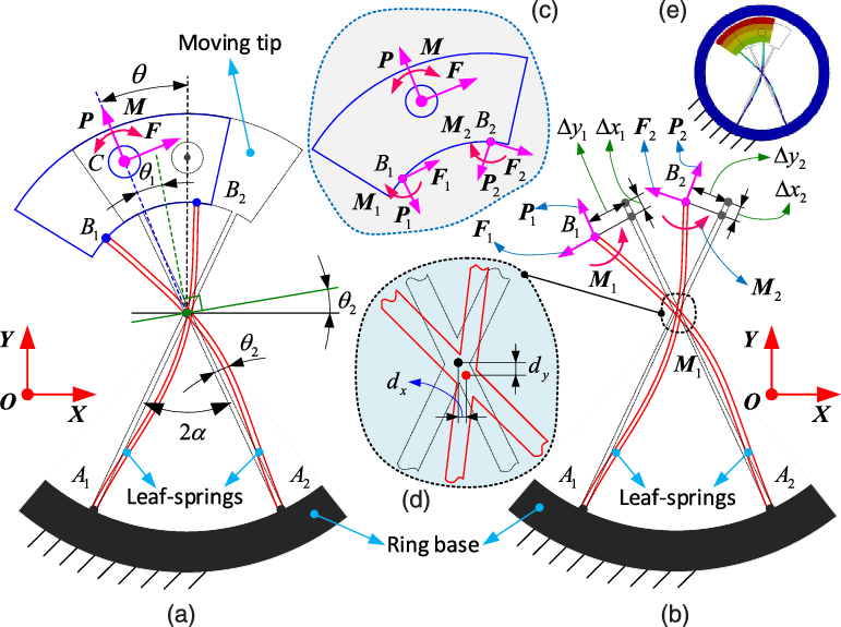
Figure 5 displays the load–displacement relationship of the unsymmetrical cartwheel pivot. The ring base of the cartwheel is assumed to be fixed on the ground. The external loads (i.e., horizontal force $\boldsymbol{{F}}$
, vertical force
$\boldsymbol{{F}}$
, vertical force $\boldsymbol{{P}}$
, and bending moment
$\boldsymbol{{P}}$
, and bending moment $\boldsymbol{{M}}$
) are imposed on the circle center of moving tip, which will cause the rotational motion of the moving tip (the deformations of leaf springs provide the rotation motion). As the two triangle pivots are different in this unsymmetrical cartwheel pivot, the rotation angles in the upper and lower triangle pivot will be different (regarded as
$\boldsymbol{{M}}$
) are imposed on the circle center of moving tip, which will cause the rotational motion of the moving tip (the deformations of leaf springs provide the rotation motion). As the two triangle pivots are different in this unsymmetrical cartwheel pivot, the rotation angles in the upper and lower triangle pivot will be different (regarded as $\theta _{1}$
and
$\theta _{1}$
and $\theta _{2}$
, respectively) under the given external loads. To analyze the force distribution in the leaf springs under the external loads, the exploded view is plotted to analyze better the generated force and displacements in cartwheel pivot (seen as Fig. 5 (b) and (c)). The center drift, which will influence the rotation accuracy of cartwheel pivot and DFMR, is defined and illustrated in Fig. 5 (d).
$\theta _{2}$
, respectively) under the given external loads. To analyze the force distribution in the leaf springs under the external loads, the exploded view is plotted to analyze better the generated force and displacements in cartwheel pivot (seen as Fig. 5 (b) and (c)). The center drift, which will influence the rotation accuracy of cartwheel pivot and DFMR, is defined and illustrated in Fig. 5 (d).
The cartwheel pivot can be regarded as a flexural mechanism, which is constituted by two triangle pivots that connected in centrosymmetric. Thus, modeling the unsymmetrical cartwheel pivot can be equivalented to analyzing the deformation of two triangle pivots under external loads, respectively.
The ring base of cartwheel pivot is assumed to be fixed on the ground, and the external loads (horizontal force $\boldsymbol{{F}}$
, vertical force
$\boldsymbol{{F}}$
, vertical force $\boldsymbol{{P}}$
, and bending moment
$\boldsymbol{{P}}$
, and bending moment $\boldsymbol{{M}}$
) are imposed on the circle center of the moving tip to drive the rotation of cartwheel pivot, which imitates the real force condition caused by SMA wires. Under this situation, the rotational motion is achieved by the deformation of the leaf springs to balance the external force.
$\boldsymbol{{M}}$
) are imposed on the circle center of the moving tip to drive the rotation of cartwheel pivot, which imitates the real force condition caused by SMA wires. Under this situation, the rotational motion is achieved by the deformation of the leaf springs to balance the external force.
According to the exploded view of cartwheel pivot in Fig. 5 (b), the force equilibrium balance equation can be established as follows:
 \begin{align} \begin{cases} \left(P_{2}-P_{1}\right)\sin \alpha +\left(F_{1}+F_{2}\right)=F\\[5pt] \left(P_{1}+P_{2}\right)\cos \alpha +\left(F_{1}-F_{2}\right)=P \end{cases} \end{align}
The moment equilibrium balance equation can be established similarly as follows:
 \begin{equation} \begin{array}{l} \left(M_{1}+M_{2}\right)+\left[\left(P_{1}-P_{2}\right)\cos \alpha +\left(F_{1}+F_{2}\right)\sin \alpha \right]L\sin \alpha \cos \theta _{1}\\[5pt] -\left[\left(P_{1}+P_{2}\right)\sin \alpha -\left(F_{1}-F_{2}\right)\cos \alpha \right]\text{\em L}\sin \alpha \cos \alpha =M \end{array} \end{equation}
where $F$
,
$F$
, $P,$
and
$P,$
and $M$
are the norms of the external load vectors (i.e., horizontal force
$M$
are the norms of the external load vectors (i.e., horizontal force $\boldsymbol{{F}}$
, vertical force
$\boldsymbol{{F}}$
, vertical force $\boldsymbol{{P}}$
, and bending moment
$\boldsymbol{{P}}$
, and bending moment $\boldsymbol{{M}}$
, respectively).
$\boldsymbol{{M}}$
, respectively). $P_{1}$
and
$P_{1}$
and $P_{2}$
,
$P_{2}$
, $F_{1}$
and
$F_{1}$
and $F_{2}$
,
$F_{2}$
, $M_{1}$
and
$M_{1}$
and $M_{2}$
are horizontal forces, vertical forces, and bending moments at points
$M_{2}$
are horizontal forces, vertical forces, and bending moments at points $B_{1}$
and
$B_{1}$
and $B_{2}$
, respectively.
$B_{2}$
, respectively. $\alpha$
is the half-angle of the intersection of the two leaf springs.
$\alpha$
is the half-angle of the intersection of the two leaf springs. $\theta _{1}$
is the rotation angle of the moving tip.
$\theta _{1}$
is the rotation angle of the moving tip. $L$
is the leaf spring length of upper triangle pivot, which can be expressed as
$L$
is the leaf spring length of upper triangle pivot, which can be expressed as $L=L_{w}-L_{b}$
(Fig. 3).
$L=L_{w}-L_{b}$
(Fig. 3).
In addition, the geometric constraint equation of cartwheel pivot after deformation can be established as
 \begin{align} \begin{cases} \left(\Delta _{y1}-\Delta _{y2}\right)\cos \alpha +\left(\Delta _{x1}+\Delta _{x2}\right)\sin \alpha =2\sin \alpha \left(1-\cos \theta _{1}\right)\\[5pt] \left(\Delta _{y1}+\Delta _{y2}\right)\sin \alpha +\left(\Delta _{x1}-\Delta _{x2}\right)\cos \alpha =2\sin \alpha \sin \theta _{1} \end{cases} \end{align}
where $\Delta_{x1}$
and
$\Delta_{x1}$
and $\Delta_{y1}$
,
$\Delta_{y1}$
, $\Delta_{x2}$
and
$\Delta_{x2}$
and $\Delta_{y2}$
are the moving distance of points
$\Delta_{y2}$
are the moving distance of points $B_{1}$
and
$B_{1}$
and $B_{2}$
in
$B_{2}$
in $\boldsymbol{{X}}$
and
$\boldsymbol{{X}}$
and $\boldsymbol{{Y}}$
directions, respectively. Then, the relationship between the loads and displacements for a single triangle pivot can be obtained by combining the above five equations (i.e., two force balance equations, one-moment balance equation, and two geometrical constraint equations). However, as the above-established equations are too complicated to obtain the analytic solutions under the given external loads, the numerical method (e.g., iterative arithmetic) was adopted by the researchers to obtain the numerical solution but is too time consuming for the real-time application.
$\boldsymbol{{Y}}$
directions, respectively. Then, the relationship between the loads and displacements for a single triangle pivot can be obtained by combining the above five equations (i.e., two force balance equations, one-moment balance equation, and two geometrical constraint equations). However, as the above-established equations are too complicated to obtain the analytic solutions under the given external loads, the numerical method (e.g., iterative arithmetic) was adopted by the researchers to obtain the numerical solution but is too time consuming for the real-time application.
Some researchers have devoted themselves to the load–displacement analyses of triangle pivot. The corresponding methods for solving the above-established equations to get the rotational displacement under external loads were proposed. Thus, only the result for the load–displacement equation is displayed for a better understanding of the relationship between load input and displacement output, and the detailed process for deriving Eq. (4) has been omitted for refining this paper.
 \begin{equation} \theta =\frac{15\cos \alpha \left(m+f\cos \alpha \right)}{p\left(2+15\cos ^{2}\alpha \right)+120\cos \alpha } \end{equation}
The characteristic of a single triangle pivot for the load–displacement relationship is shown as Eq. (4), in which the nondimensional parameters (i.e., $m$
,
$m$
, $f$
, and
$f$
, and $p$
) are used to simplify the equation and make it more convenient for the usage.
$p$
) are used to simplify the equation and make it more convenient for the usage.
 \begin{equation} m=\frac{ML}{EI},f=\frac{FL}{EI},p=\frac{PL}{EI} \end{equation}
where $M$
,
$M$
, $F,$
and
$F,$
and $P$
are the norms of horizontal force vector (
$P$
are the norms of horizontal force vector ( $\boldsymbol{{F}}$
), vertical force vector (
$\boldsymbol{{F}}$
), vertical force vector ( $\boldsymbol{{P}}$
), and bending moment vector (
$\boldsymbol{{P}}$
), and bending moment vector ( $\boldsymbol{{M}}$
), respectively.
$\boldsymbol{{M}}$
), respectively.
It can be seen from Eq. (4) that the displacement of the triangle pivot is relative to the horizontal force, $\boldsymbol{{F}}$
, and the bending moment,
$\boldsymbol{{F}}$
, and the bending moment, $\boldsymbol{{M}}$
, while the vertical force,
$\boldsymbol{{M}}$
, while the vertical force, $\boldsymbol{{P}}$
, can actively change the stiffness of triangle pivot. Besides the external forces that can change the characteristics of triangle pivot actively, the intersection angle of two leaf springs (
$\boldsymbol{{P}}$
, can actively change the stiffness of triangle pivot. Besides the external forces that can change the characteristics of triangle pivot actively, the intersection angle of two leaf springs ( $2\alpha$
), as well as the ratio of upper and lower triangle pivot (
$2\alpha$
), as well as the ratio of upper and lower triangle pivot ( $\lambda$
), is also making the contribution to the characteristics of triangle pivot, which are illustrated as Fig. 6.
$\lambda$
), is also making the contribution to the characteristics of triangle pivot, which are illustrated as Fig. 6.
Structure illustration of the unsymmetrical cartwheel pivot. Two similar triangle pivots (i.e., upper and lower triangle pivots) with ratio $\lambda$
(i.e., intersection angle of two leaf springs) constitute the flexural parts of the cartwheel pivot.
$\lambda$
(i.e., intersection angle of two leaf springs) constitute the flexural parts of the cartwheel pivot.
As the unsymmetrical cartwheel pivot is constructed by two similar triangle pivots (parameters are different), the individual rotational displacements are different under the given external loads. Thus, the cartwheel pivot is divided into two triangle pivots (i.e., upper and lower triangle pivots in Fig. 6) to calculate the overall rotation displacement by adding the componential results, respectively.
The external loads (i.e., horizontal force, $\boldsymbol{{F}}$
, vertical force,
$\boldsymbol{{F}}$
, vertical force, $\boldsymbol{{P}}$
, and bending moment,
$\boldsymbol{{P}}$
, and bending moment, $\boldsymbol{{M}}$
) are imposed on the circle center of the rotational tip (Fig. 6). In the initial situation, there is no external load on the cartwheel pivot. Then the loads are imposed at the tip to study the load–displacement characteristics. After that, the static equations of upper and lower pivots are established separately to calculate the total rotational displacement.
$\boldsymbol{{M}}$
) are imposed on the circle center of the rotational tip (Fig. 6). In the initial situation, there is no external load on the cartwheel pivot. Then the loads are imposed at the tip to study the load–displacement characteristics. After that, the static equations of upper and lower pivots are established separately to calculate the total rotational displacement.
The lower triangle pivot, which has a similar structure with the upper triangle pivot, is regarded to have a different rotation angle, $\theta _{2}$
, with the upper triangle pivot. The loads imposed on the lower triangle pivot are calculated at first based on the load balance equation of the lower triangle pivot, which can be expressed as
$\theta _{2}$
, with the upper triangle pivot. The loads imposed on the lower triangle pivot are calculated at first based on the load balance equation of the lower triangle pivot, which can be expressed as
 \begin{align} \begin{cases} F_{1}=-F\cos \theta _{2}+P\sin \theta _{2}\\[5pt] P_{1}=P\cos \theta _{2}-F\sin \theta _{2}\\[5pt] M_{1}=M+2F\lambda L_{b}\cos \alpha \cos \theta _{2}-2P\lambda L_{b}\cos \alpha \sin \theta _{2} \end{cases} \end{align}
where $F_{2}$
,
$F_{2}$
, $P_{2}$
, and
$P_{2}$
, and $M_{2}$
are norms of the horizontal force, vertical force, and bending moment imposed on the lower triangle pivot, respectively;
$M_{2}$
are norms of the horizontal force, vertical force, and bending moment imposed on the lower triangle pivot, respectively; $\theta _{2}$
is the rotational angle of the upper triangle pivot; and
$\theta _{2}$
is the rotational angle of the upper triangle pivot; and $\lambda$
is the ratio between the length lower triangle pivot and upper triangle pivot.
$\lambda$
is the ratio between the length lower triangle pivot and upper triangle pivot.
After establishing the external loads that imposed on the lower triangle pivot using Eq. (6), the displacement, $\theta _{1}$
, can be calculated by substituting Eq. (6) into Eq. (4), which can be expressed as
$\theta _{1}$
, can be calculated by substituting Eq. (6) into Eq. (4), which can be expressed as
 \begin{equation} \theta _{1}=\frac{15\cos \alpha \left(2\lambda -1\right)\left[\left(f{\theta }_{2}^{2}+2p\theta _{2}\right)\cos \alpha -2\left(m+f\cos \alpha \right)\right]}{\left(2+15\cos ^{2}\alpha \right)\left[p{\theta }_{2}^{2}-2f\theta _{2}-2p\right]-240\cos \alpha } \end{equation}
As the two triangle pivots (i.e., upper and lower triangle pivots) are different in the unsymmetrical cartwheel, the angle displacements are different under the external loads (i.e., horizontal force, $\boldsymbol{{F}}$
, vertical force,
$\boldsymbol{{F}}$
, vertical force, $\boldsymbol{{P}}$
, and bending moment,
$\boldsymbol{{P}}$
, and bending moment, $\boldsymbol{{M}}$
), which are relative to the size of the triangle pivots.
$\boldsymbol{{M}}$
), which are relative to the size of the triangle pivots.
The total displacement of one unsymmetrical cartwheel pivot can be obtained by adding the two displacements in upper and lower triangle pivots together. As three identical cartwheel pivots are used in constructing the SDFRM, which are equally spaced around the rotational center, the rotational displacement, $\theta$
, can be expressed as
$\theta$
, can be expressed as
 \begin{equation} \theta =\left(\theta _{1}+\theta _{2}\right)/3 \end{equation}
As the cartwheel pivot adopted in SDFRM is constituted by two similar triangle pivots, the rotation displacements in the upper and lower triangle pivots are different, which is quite different from the traditional cartwheel pivot. Thus, the total displacement of the unsymmetrical cartwheel pivot should be obtained by calculating the two triangle pivots, respectively. In addition, the SDFRM proposed in this paper is constructed by three parallelly connected cartwheel pivots, leading to the load–displacement relationship becoming more complicated, which should be paid attention to modeling the load–displacement characteristic for the following control algorithm design.
3.2 Modeling the SMA wire
After establishing the load–displacement model of the selected mechanism (i.e., cartwheel pivot), the model of SMA wire is carried out for obtaining the overall model (i.e., cartwheel and SMA wire) of the rotational mechanism for the preparation of the following experiments. The constitutive thermal effect equation of the SMA wire is adopted to establish the degree of phase transformation with the variation of external temperature. In addition, the heat dissipation in the SMA wires is also considered, enabling us to establish the equation between power consumption and temperature variation for establishing the whole closed-loop system (i.e., from the power consumption to output displacement of the rotational system).
Based on the previous research, the basic constitutive thermal effect equation for an SMA wire can be expressed as [Reference Bodaghi, Damanpack, Aghdam and Shakeri25, Reference Bodaghi, Shakeri and Aghdam26]
 \begin{equation} \dot{\sigma }=E\dot{\varepsilon }+{\unicode[Times]{x03C9}} \dot{\xi }+{\unicode[Times]{x03B8}} \dot{T} \end{equation}
where $\sigma$
is the stress,
$\sigma$
is the stress, $E$
is the Young’s modulus,
$E$
is the Young’s modulus, $\varepsilon$
is the strain of the wire,
$\varepsilon$
is the strain of the wire, ${\unicode[Times]{x03B8}}$
is the thermoelastic coefficient,
${\unicode[Times]{x03B8}}$
is the thermoelastic coefficient, $T$
is the current temperature,
$T$
is the current temperature, ${\unicode[Times]{x03C9}}$
is the phase transformation coefficient, and
${\unicode[Times]{x03C9}}$
is the phase transformation coefficient, and $\xi$
is the martensite fraction. The symbol
$\xi$
is the martensite fraction. The symbol $(\!\cdot\!)$
represents the time derivation.
$(\!\cdot\!)$
represents the time derivation.
It can be seen from Eq. (9) that the SMA wire is balanced by the internal stress, stain, martensite fraction, and temperature. In most of the time, the temperature, $T$
, is the input variable, and the stress, stain, and martensite fraction of SMA wire, as the output variables, are changed correspondingly.
$T$
, is the input variable, and the stress, stain, and martensite fraction of SMA wire, as the output variables, are changed correspondingly.
In the heating stage, the temperature in the SMA wire is increasing gradually, and the martensite fraction (i.e., from martensite to austenite), $\xi$
, can be expressed as
$\xi$
, can be expressed as
 \begin{equation} \xi =\frac{\xi _{M}}{2}\left\{\cos \left[a_{A}\left(T-A_{s}\right)+b_{A}\sigma \right]+1\right\} \end{equation}
In the cooling stage, the temperature in the SMA wire is decreasing gradually, and the martensite fraction (i.e., from austenite to martensite), $\xi$
, can be expressed as
$\xi$
, can be expressed as
 \begin{equation} \xi =\frac{1-\xi _{A}}{2}\cos \left[a_{M}\left(T-M_{f}\right)+b_{M}\sigma \right]+\frac{1+\xi _{A}}{2} \end{equation}
where $M_{s}$
,
$M_{s}$
, $M_{f}$
,
$M_{f}$
, $A_{s}$
, and
$A_{s}$
, and $A_{f}$
are the temperatures of the martensite start, martensite finish, austenite start, and austenite finish, respectively.
$A_{f}$
are the temperatures of the martensite start, martensite finish, austenite start, and austenite finish, respectively. $\xi _{A}$
and
$\xi _{A}$
and $\xi _{M}$
are the fractions of austenite and martensite in the initial state.
$\xi _{M}$
are the fractions of austenite and martensite in the initial state. $a_{A}$
,
$a_{A}$
, $b_{A}$
,
$b_{A}$
, $a_{M}$
, and
$a_{M}$
, and $b_{M}$
are the constants derived from four transition temperature.
$b_{M}$
are the constants derived from four transition temperature.
As the SMA wire is heated by applying the current on the two ends, the temperature in the SMA wire can be calculated by establishing the equation between power consumption and heat dissipation using the law of energy conservation, as seen in Eq. (12).
 \begin{equation} \frac{V^{2}}{R}=m_{w}c_{p}\dot{T}+hA_{w}\left(T-T_{amb}\right) \end{equation}
where $V$
is the voltage applied on the SMA wire;
$V$
is the voltage applied on the SMA wire; $R$
is the resistance of the wire;
$R$
is the resistance of the wire; $m_{w}$
is the mass of the SMA wire;
$m_{w}$
is the mass of the SMA wire; $c_{p}$
is the heat constant of SMA wire;
$c_{p}$
is the heat constant of SMA wire; $\dot{T}$
is the rate of the temperature variation of the SMA wire;
$\dot{T}$
is the rate of the temperature variation of the SMA wire; $h$
is the heat convection factor, which can be expressed as
$h$
is the heat convection factor, which can be expressed as $h=h_{0}+h_{2}T^{2}$
;
$h=h_{0}+h_{2}T^{2}$
; $A_{w}$
is the surface area of the SMA wire;
$A_{w}$
is the surface area of the SMA wire; $T$
is the current temperature of the wire; and
$T$
is the current temperature of the wire; and $T_{amb}$
is the room temperature.
$T_{amb}$
is the room temperature.
After establishing the models of cartwheel pivot (Section 3.1) and SMA wire (Section 3.2), the overall model of SDFRM can be obtained by connecting the result of them. The working process of the system can be described as when the voltage is applied on the SMA wires from the initial stage (room temperature), the temperature on the SMA wire will be increased to force the phase transformation from martensite to austenite, and then the stress and strain will be produced. As a result, the SDFRM, constituted by three cartwheel pivots, is driven to rotate around the center axis by the SMA wires.
4. Model validation and dynamic performances test
With the prototyped SDFRM, the experimental setup (i.e., power supply, control system, temperature sensor, and angular sensor) is prepared for validating the models established in Section 3. After that, the control algorithm is designed to obtain the dynamic performances (i.e., step response and tracking response) of SDFRM for investigating the performance of the overall system (i.e., constituted by the cartwheel pivots and SMA wires).
4.1 Experimental setup
The SDFRM, which is composed of three flexural cartwheel pivots, is no longer just a passive rotational mechanism but can achieve active rotation when combined with the intelligent actuator (SMA wire). As the case study, 12 pulleys are circumferentially mounted on each cartwheel pivot to guide the twining/shrinking of the SMA wires.
The configuration of the experimental platform (Fig. 7) is shown as follows:
The experimental setup and structural illustration of SDFRM: a) the experimental setup of SDFRM for testing the rotational output under different voltages; b) the structure illustration of SDFRM (six sets of SMA wires are installed); c) the detail structure illustration of a single cartwheel pivot. Note: 12 pulleys are equally spaced around the outer ring of one cartwheel pivot to decrease the friction caused by SMA wires; the plastic screws and washers are used for the insulation of SMA wires.
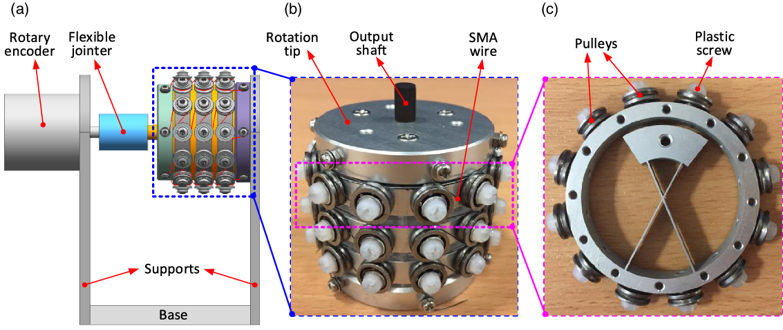
1. The base of the system is fixed on the support table.
2. Three cartwheel pivots (Fig. 7(c)) are installed on the base in sequence with 120° intervals and regarded to be fully connected with each other for constructing the SDFRM (Fig. 7(b)).
3. The rotational tip is connected to the three cartwheel pivots by the support shafts (Fig. 4), and the rotation of the tip is only achieved by the flexible deformation of the leaf springs in the cartwheels.
4. Rotary encoder (OMRON, type: E6B2-CWZ6C, 2000 P/R) is used to capture the rotation of the output tip.
5. Flexible jointer is used to connect the rotary encoder and SDFRM together.
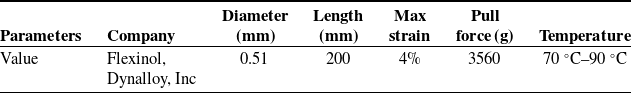
6. 1–6 sets of SMA wires are used to drive the rotation of the system. Parameters of the SMA wire can be checked from Table I.
7. Temperature sensor (NTC10KB3950) and current sensor (MC33926) are used to feedback the responses in SMA wires during the experiments.
8. Control system (i.e., hardwire, control algorithm, and human–computer interaction system) is constructed to implement the experiment and display the data collected from sensors at the same time.
The basic parameters of the SMA wires (e.g., diameter, length, and max strain) used in the gripper are shown in Table II. For the thermomechanical properties of the SMA wire, they can be checked from the existing publication [Reference Guo, Pan, Wee and Yu29].
The parameters of the SMA wire used in the rotational joint.
The hardwire connection of the control system for SDFRM is shown in Fig. 8. First, the graphical user interface is designed for sending the commands to the slave computer system and displaying the data collected from the sensors conveniently. Then, the control algorithm is programmed in the slave computer system to validate the model developed in section. After that, the power supper is adopted to drive the rotation of SDFRM and feed the operation of slave computer and sensors (i.e., rotary encoder, temperature sensor, and current sensor). At last, the A/D converters are used to transfer the analog single to the digital single.
Block diagram of the experimental setup for the SDFRM.

The working process of the control system shown in Fig. 8 can be illustrated as follows: first, when the command is sent from the host computer to the slave computer, the control algorithm running in the slave computer (shown as Fig. 10) will generate the analog single to the voltage amplifier, where the corresponding voltage is generated to power the SDFRM. Then, the rotation displacement will be generated after the voltage imposed on the SMA wires. After that, the temperature and current in the SMA wires are detected by the sensors and transferred into digital singles. At last, the signals of three channels (i.e., rotation angle, temperature, and current) are transmitted to the slave computer for the closed-loop control algorithm.
Model validation and performance test of SDFRM. The voltages (i.e., from 3 V to 8 V with 1 V increment) were utilized on the system for the model validation and performance test. Note: the material of the cartwheel pivot used in this paper is Aluminum 7070 (elastic modulus: 71.7 GPa; Poisson ratio:0.33).

4.2 Model validation
After configuring the experimental platform, the validation process of the overall system (i.e., cartwheel pivot and SMA wire) can be implemented under the different voltages. For doing this, the voltages applied on the SMA wires are gradually changed to actively adjust the external loads on the system, in which the characteristics (i.e., output range and response speed) of the system can be tested.
The validation process of SDFRM was conducted in this section to prove the model (cartwheel pivots and SMA wires) developed in Section 3. Based on the equations established in Section 3, the temperature of SMA wires can be controlled by changing the voltage, then the stress and strain will be produced by the phase transformation of SMA wire to actuate the rotation of SDFRM. Thus, to validate the proposed model, the voltage (i.e., 5 V) was imposed on the SMA wires to actuate the rotation of the system, and then the rotation motion was captured by the encoder system to be further compared with the theoretical calculation. In addition, for checking the performances of the system, different voltages (i.e., from 3 V to 8 V with 1 V increment) were applied on the system to check the output of the system, seen as Fig. 9.
It can be seen from Fig. 9 that the results obtained from the experiment and calculation can match well with each other under the selected voltages, which proves the correctness of the model proposed in this paper. The overall error between the test and calculation was 3.8% (i.e., 4.0% for 4 V and 3.6% for 5 V, respectively) under the given voltages on SDFRM. Taking the 5 V as an example, compared to the modeling accuracy in the cooling stage, the higher accuracy was achieved in the heating stage (i.e., 2.3% in the heating stage and 4.8% in the cooling stage, respectively). At the end of the cooling stage, the error between test and calculation was increasing after 15 s and kept constant (i.e., 0.1°) after 18 s. This happened mainly due to the property variation (i.e., lattice strain) of SMA material. In addition, the responses of SDFRM under different voltages (i.e., from 3 V to 8 V with 1V increment) were tested for further research of the performance. Overall, with the increase of voltage, the output of the system was increasing correspondingly. Specifically, the maximum output of SDFRM under 3 V, 4 V, 5 V, 6 V, 7 V, and 8 V was 0.3°, 2.4°, 3.0°, 3.5°, 3.7°, and 3.8°, respectively.
4.3 Tracking performance test
The aim of the tracking performance tests is to check the real-time characteristics of SDFRM when it is performing the continuous tracking tasks (i.e., step and continuous tracking, respectively). In order to check the real-time tracking performance of the SDFRM, the closed-loop control algorithm is designed.
4.3.1 Control algorithm design
The flowchart of the control algorithm for the dynamic performance test of the SDFRM system is shown in Fig. 10. The detail process can be illustrated as follows: first, when the desired rotation angle of the SDFRM is given for the control system, the actual angle of the SDFRM will be read and compared with the desired angle. If the difference between the desired value and actual value is larger than the setting value, $\delta$
, the voltage will be generated by the controller to heat the SMA wires; otherwise, the SMA wires will stop being heating; at the same time, the current and temperature sensors are working to feedback the real-time data to the control system for the security; then, with the increase of the temperature of the SMA wires, the phase transformation will be happened inside the SMA wire, where the strain/stress will be generated to drive the rotation of the SDFRM; at last, the generated stress from the SMA wires will actuate the plastic deformation of the cartwheel pivot (i.e., rotation motion).
$\delta$
, the voltage will be generated by the controller to heat the SMA wires; otherwise, the SMA wires will stop being heating; at the same time, the current and temperature sensors are working to feedback the real-time data to the control system for the security; then, with the increase of the temperature of the SMA wires, the phase transformation will be happened inside the SMA wire, where the strain/stress will be generated to drive the rotation of the SDFRM; at last, the generated stress from the SMA wires will actuate the plastic deformation of the cartwheel pivot (i.e., rotation motion).
Flowchart of the closed-loop control for the SDFRM.

4.3.2 Step response
The step response is performed to study the performance of the SDFRM under the given step input. The response speed of SDFRM has much relationship with the voltage and current, which can cause the temperature variation of the SMA wires. The temperature is the limitation for the response speed, as the SMA wire will be degenerated/broken when the temperature is higher than the required limitation. Overall, the current and temperature in SMA wire should be limited to a reasonable range to protect the system. Under these limitations, the parameter selection for the control algorithm is becoming more critical to obtain a high response speed without damaging the SMA wire.
The step response of the SDFRM, as well as the current and temperature variation, is shown in Fig. 11.
The step response of SDFRM under different inputs.

Fig. 11 presents the step responses of SDFRM with the proposed control algorithm, in which the rotation angles were varied from 0° to 2° with 0.5° increment at the first half of the test. Then the rotation angles were decreased from 2° to 0° with 0.5° increment at the rest of the test. From the experimental results, it can be found that the SDFRM can quickly respond to the given inputs (i.e., around 0.2 s) with good stabilization accuracy (i.e., average error: 1.5%). Precisely, the rotation errors in the first half of the test (i.e., rotation increasing stage, average error: 0.7%) were much smaller than the errors in the right part of the test (i.e., rotation decreasing stage, average error: 2.3%). This is due to the fact that the heating speed of SMA wires (i.e., length decrease) is quicker than the cooling speed (i.e., length recovery). This phenomenon is more apparent when the absolute remaining strain in the SMA wire is closing to zero, which can be proved at the time when the system is trying to back to the initial position (i.e., 0° rotation).
4.3.3 Continuous tracking response
The continuous tracking response of SDFRM is tested in this section by tracking the desired sinusoidal trajectories with different amplitudes and frequencies (seen in Fig. 12). The continuous tracking response of SDFRM represents the ability to track the given trajectories accurately and rapidly. Most of the time, the higher gain can increase the response speed of the system. However, the error will be enlarged to decrease the accuracy of the system.
The continuous tracking responses and errors of SDFRM for tracking the trajectories with different periods: a) the trajectory (i.e., amplitude: 0.75 mm, cycle: 20 s) with 1 mm offset to the positive direction; b) the period of the trajectory is 10 s (other parameters are same with (a)).

The experiments are divided into two groups based on the frequency of the trajectories (Fig. 12 (a): 20 s, Fig. 12 (b): 10 s). Then, the closed-loop control system was implemented to track the given path. The results are shown in Fig. 12.
It can be seen from Fig. 12 that the SDFRM can track the given trajectories (i.e., amplitude: 0.75 mm, offset: 1 mm, cycle: 20 s and 10 s in (a) and (b), respectively) with high accuracy. In Fig. 12 (a), the tracking error of SDFRM is within 0.05 mm. With the decrease of the period, the tracking error increases correspondingly (within 0.2 mm). This is because the speed of the phase transformation of the SMA wire has a limitation, which restricts the response speed of the SDFRM. In addition, from Fig. 12 (b), the peaks of tracking error are mostly happened at the down section of the sinusoidal curve, which reflects that the phase transformation speed from austenite to martensite is lower than the martensite to austenite. This is partly due to the fact that the natural dissipation speed is lower than the heating speed. Thus, in order to improve the tracking speed and accuracy, the assistant heat dissipation method may be a good option.
It needs to note that the above experiments (i.e., joint rotation that actuated by SMA wires) were carried out under the internal load of the cartwheel pivots, which is a complex nonlinear load that is caused by the material deformation. With the increase of the bending angle of SDFRM, the higher internal load will be generated to balance with the stress of the SMA wires. This is a complex coupling process as the final rotation angle of the SDFRM is decided by the nonlinearities of the cartwheel pivots and the thermomechanical effects of the SMA wires. As the main aim of this paper is to demonstrate the feasibility of combining the SMA wire with the flexural-based mechanism (cartwheel pivot was selected as an example) to reduce the complexity of the conventional rotational joints, the aforementioned complex nonlinearities and thermomechanical couplings are not considered at the current stage. In addition, as the nonlinear internal loads (i.e., caused by the material deformation of the cartwheel pivot) have been considered during the modeling and experiments, the additional tests under the external linear loads (e.g., constant dead weight hanged at the end) were not needed at the current stage.
Comparing with the existing SMA-based rotational mechanisms, the developed SMA-based joints have the potential to largely reduce the dimension and improve the accuracy, as the restoring force can be provided by the material deformation of the flexural hinges. Specifically, comparing with an existing example rotation joint [Reference Bodaghi, Shakeri and Aghdam26], the dimension is 60 mm for the diameter in this paper, while 200 mm length in the reference paper; the absolute positioning accuracy is 98.5% in this paper, compared with 90% in the reference paper.
In this part, after validating the kinematic model proposed in Section 3, the dynamic performances (i.e., step response and tracking response, respectively) were tested with the developed closed-loop control system. It can be seen from the validation result that the proposed model can be used to predict the kinematic response of SDFRM. In addition, with the developed closed-loop system, the SDFRM can realize the high-speed tracking with reasonable accuracy. The results show that it is feasible to combine the flexural-based mechanism with the intelligent actuator (i.e., SMA wire) to develop the new generation of rotational joints.
5. Conclusion
In this paper, a class of active rotational joints, which were constructed by the combination of flexural-based mechanisms (i.e., cartwheel mechanism and cross-leaf pivot) and intelligent actuator (i.e., SMA wire as an example), was proposed to improve the performance of the rotational joints in precision engineering. Specifically, a rotational mechanism was developed as an intelligent joint to realize the active rotation with the smart actuator, which develops the combination of flexible pivot and smart actuators. As a case study, the cartwheel pivot was selected in this paper to construct the flexible rotational mechanism to be combined with the SMA wires, which was followed by the corresponding theoretical modeling and dynamic tests. The novelties of the proposed system developed can be summarized as follows.
First, the first attempt to combine the flexural-based mechanism with the intelligent actuator to develop a new kind of rotational joint is novel in this paper. The developed rotational mechanism can be ideally applied as an actively rotational joint (with the build-in actuator) to primarily minimize the dimension of robotic system. More importantly, the relative motion between the adjacent parts was achieved by the material deformation of the flexural-based mechanism, enabling the developed method to be used in damp environments with little maintenance in the future. In addition, the lightweight and high-power weight actuator (i.e., SMA wire) can primarily reduce the weight of the rotational joint, which is another potential advantage to reduce the weight of the overall system.
Second, based on the concept developed in this paper (i.e., combining flexural mechanism and SMA wire to construct the rotational joint), the static model of flexural mechanism and thermal effect model of SMA wire were established to study the performance of the system (i.e., rotation output) with the relationship of inputs (i.e., the voltage of SMA wire). As a case study, the cartwheel pivot with the unsymmetrical distribution of spring leaf was adopted to provide the appropriate backing force and limited axis drift for combining with SMA wires. Then the static model of SDFRM was established by combining the kinematic models of cartwheel pivot and SMA wire.
Third, with the established experimental table (i.e., the prototype of SDFRM and control system, shown in Figs. 7 and 10, respectively), the validation process was performed to check the reliability of the model proposed in this paper. It can be seen from the testing that the developed model can be validated with an error of 3.6%, which proves the correctness of the proposed model. In addition, it can also be found that the higher modeling accuracy is obtained in the heating stage (2.3%) than the cooling stage (4.8%) of the SMA actuator.
Lastly, the dynamic performances of SDFRM were tested by tracking the step signals and sinusoidal trajectories, respectively. The closed-loop control algorithm was developed to study the tracking performance of the system. Specifically, the step response results indicated that the speed of the system (i.e., 0.2 s) was high to track the given signals. From the continuous tracking experiments (i.e., sinusoidal trajectories with different cycles), the system can track the planned trajectories within the error of 0.2 mm. Due to the limitation of heat dissipation speed of SMA wires, the tracking ability was becoming hard to be increased under the natural cooling method. For further improving the response speed of the system, the advanced cooling method (i.e., air convection and heat conduction) should be adopted.
Acknowledgments
The research leading to these results has received funding from China Scholarship Council and Beijing Institute of Technology.
Conflict of interest
The author(s) declare(s) that there is no conflict of interest.


 Open access