


1. Introduction
Industry 5.0 is introduced by the European Commission 10 years after the introduction of Industry 4.0. Industry 4.0 is discussed as technology-driven, while Industry 5.0 is presented as value-driven as it suggests bringing back humans in production [Reference Xu, Lu, Vogel-Heuser and Wang1]. Accordingly, Industry 5.0 brings the human touch with semi-autonomous robots inside a hybrid workspace in a mass product personalization concept. Using the intelligence of humans combined with tireless robots, flexible manufacturing could be adapted and upgraded for a mass (product) personalization which is limited in Industry 4.0 concepts. In this perspective, robots and humans will work together in same workspace. Humans focus on more complex tasks needing interpretation and robots do repetitive tasks. In human–robot co-working (such as physical cooperation, interaction, and task sharing), when humans and robots need to work in a same workspace, preventing human–robot collisions is an important and fundamental issue. Avoiding human–robot collisions in a shared workspace is the main topic of this paper such as discussed in ref. [Reference Demir, Döven and Sezen2].
The SPADER project (Sharing Production Activities in Dynamic Environment) [Reference Meziane, Otis and Ezzaidi3], presented as a new concept for Industry 5.0, could be applicable for cable-driven parallel mechanism (CDPM). CDPM consists of several components: a fixed base, an end effector, and m-cables to connect the base to end effector by set of pulleys and actuators. Compared to serial mechanisms, there are advantages for CDPM such as a large workspace and high dynamic. Also, CDPMs can be used to move or lift heavy objects in the industry [Reference Albus, Bostelman and Dagalakis4], as haptic interfaces [Reference Otis, Nguyen-Dang, Laliberte, Ouellet, Laurendeau and Gosselin5] and high-speed manipulators [Reference Kawamura, Kino and Won6]. CDPMs are useful for applications with high dynamic and velocity demands. High dynamic significantly increases the inertial effects of the moving end effector and must be considered in the end effector wrench computation. A controller can generate appropriate cable tension distribution for given end effector trajectories.
Researchers, active in the CDPM field, have been investigating on many challenges, such as dynamic trajectory planning [Reference Zhang, Shang and Cong7] and control [Reference Khosravi and Taghirad8]. In the fully constrained CDPM, each wrench applied on the end effector can be balanced by pulling each cable with a tensile force control [Reference Gouttefarde9]. Moreover, the end effector can be moved in some poses (positions and orientations) due to the control of cables length [Reference Bosscher, Riechel and Ebert-Uphoff10], and all degrees of freedom of the end effector can be controlled through the cables.
However, to constrain the end effector, the number of cables (m) should be greater than the number of degrees of freedom (DOF) or m ≥ DOF + 1. Given the above facts, wrench-closure workspace (WCW) is introduced as a set of a feasible pose of the end effector balanced through positive tension in the cables. The WCW is dependent on the geometry of the mechanism [Reference Lim, Yang, Yeo and Mustafa11, Reference Pham, Yeo, Yang, Kurbanhusen and Chen12]. On the other hand, if m ≤ DOF, then the mechanism is known as under-constrained.
As an example of cable behaviors, the mass and elasticity of cables impact on the position accuracy of the end effector as suggested in refs. [Reference Ottaviano and Castelli13–Reference Riehl, Gouttefarde, Krut, Baradat and Pierrot15]. Moreover, in addition to cables mass and elasticity, sagging and vibration explored in refs. [Reference Ottaviano, Arena and Gattulli16, Reference Weber, Cuvillon and Gangloff17] increase the cable length and then the position accuracy. In these studies, the cables are introduced by an elastic catenary. Considering the model of cables makes the system more complex for the position/velocity control, some papers assumed cables as massless inextensible lines [Reference Ming18] connecting the attachment points on the pulley with the end effector [Reference Roberts, Graham and Lippitt19].
Cables are wound around a pulley to release or retract the cable through actuators. Pott [Reference Pott20] discussed the influence of a pulley in the winch. However, only a few authors have addressed the influence of pulleys (by modeling a pulley) on the kinematics [Reference Pott20] and dynamic simulation of CDPM [Reference Miermeister and Pott21].
In SPADER projects, the collaboration between humans and robots is required to achieve high-performance control and sensing so that operators can share the same workspace with robots. There is some traditional solution to ensure user safety by isolating the robot by fences or laser curtains. These solutions stop the robot immediately when it is very close to a human and avoid any risk of collision, limiting the task’s flexibility. So, these methods are not applicable where humans and robots collaborate in the same physical workspace. The robots should respond accurately to human actions to have safe interaction in a shared workspace. In some applications where humans and robots are working in the same workspace, robots should track the predefined trajectory and perform some tasks such as assembly processes where the contact between humans and robots can be dangerous for humans. Whereas in CDPM mechanism, cables are hanging through the workspace, they can easily interfere with end effector, obstacles such as human limbs and other cables as mentioned by Nguyen and Gouttefarde [Reference Nguyen and Gouttefarde22]. Interference among cables and limbs could distort the whole end effector trajectory and cause a quick tension drift on the cables. Collision avoidance methods have been well studied for the case of serial and parallel robots. However, it is not well developed in the case of CDPM.
Makino et al. [Reference Makino and Harada23] designed a 6-DOF CDPM with eight cables using a rotational mechanism inside the end effector. Meanwhile, when a collision among cables is detected, control of cables is proposed by rotating the end effector around the vertical axis to change the configurations of the cables.
Lahouar et al. [Reference Lahouar, Ottaviano, Zeghoul, Romdhane and Ceccarelli24] adapt path planning method for cable robots that were developed for serial manipulators. Path planning is used when the robot is closed to an obstacle. An algorithm is used to detect the collision between the robot and the obstacle and between the cable and obstacle. This approach is used to find a free collision path in CDPM, whereas in the presented paper, we present a method to track predefined trajectory as a duplicated process. The most proposed approaches focus on finding a free collision path in CDPM. Still, these methods are not applicable for some processes where the trajectory is predefined and should not be changed, such as the assembly process. Reconfiguration of CDPM’s components, such as motorized reels, may improve the capability of CDPM and increase the workspace size [Reference Gagliardini, Gouttefarde and Caro25].
Workspace presented by Trautwein [Reference Trautwein, Reichenbach, Pott and Verl26] is used to determine the geometry of cable-driven parallel robots. The theoretical kinematics of CDPM and reconfiguration CDPM is proposed. Analyzing workspace by considering the collision avoidance among cables or obstacles is not presented. Whereast to avoid collision and track the predefined trajectory, the adaption of components positions or the workspace of the CDPM as geometric reconfiguration theory is proposed.
Gagliardini et al. [Reference Gagliardini, Gouttefarde and Caro25] focuses on relocation of attachment points on the base of Reconfigurable Cable Driven Parallel Mechanism or RCDPMs. According to the environment, the designer divides the defined workspace in n parts. Trying to predict the collision between cables and object in the workspace can be used to divide the workspace. Each part can be covered and represented by just one configuration. So, for each configuration, the designer defines the set of possible locations for attachment points. By placing the attachment points on the possible locations, many CDPM configurations can be generated. There are set of constraints such as interference between cables and wrench feasibility. So, some configurations satisfying the constraints are selected. Combination of these configuration is needed to optimize presented objective functions to maximize productivity and minimize reconfiguration time. The reconfiguration process in 10 steps is explained in ref. [Reference Gagliardini, Gouttefarde and Caro25]. To pass from one configuration to another, one or more cables must be disconnected from their initial attachment points and connected to new attachment points location. New attachment points position for all the configurations can be computed by an optimization algorithm to satisfy a set of constraints that are defined by the designer. This proposed method is used to reduce computational time, but it needs the knowledge of designer about trajectory to divide the workspace in n parts.
Xu and Park [Reference Xu and Park27] used rapidly exploring random tree (RRT) method to address moving cube obstacle avoidance. The Gilbert–Johnson–Keerthi (GJK) algorithm is used to detect collision. In ref. [Reference FarzanehKaloorazi, Masouleh and Caro28], presented by Farzaneh Kaloorazi et al., obstacles are considered as a circle- (planar case) or spherical (spatial case)-shaped, and interference with limbs and end effector edges are discussed. Obstacle-free workspace of two parallel manipulators (a 3-RPR PM and 6-DOF Gough–Stewart) introduced an interval-based methodology. Meanwhile, this methodology is known as a computationally intensive approach due to the limitation of interval analysis. It causes high computing time in a high-degree equations.
Youssef and Otis [Reference Youssef and Otis29] introduced an algorithm to prevent the collision between cables, whereas the trajectory of the end effector is unchanged. An algorithm is used to detect the contact between the two cables and which cables are in a higher position. So, it moves up the attachment points to increase the distance between the two cables to the safest threshold. In fact, first, the length of the cable and the pose of the end effector are determined, and second, distance between the cables are defined. If the distance between the two cables is less than the tolerance, the cable tension is computed, and finally, an increment on the attachment points is obtained.
This paper aims to model and analyze the reconfiguration of a 6-DOF parallel mechanism driven by eight cables to avoid collisions among cables and human limbs in the shared workspace. In this paper, a fully constrained CDPM can be introduced when the attachment points on the rails move vertically up and down. The length of cables can be modified according to the relocation of attachment points. The contribution of this paper is the collision avoidance among cables and human limbs (such as a moving obstacle in a dynamic workspace) in CDPM using Karush-Kuhn-Tucker (KKT) method. This idea applies by moving the linear displacement of attachment points on the rails to increase the shortest distance between cables and human limbs to a safe distance. This distance is computed by the KKT method as a collision detection algorithm. So, this algorithm can detect obstacles as quickly as possible. After distance detection, the algorithm moves reels or attachment points on the rails while keeping the desired trajectory of the end effector unchanged. Workspace analysis for all poses of the end effector is one of the important issues in designing CDPM. The effect of relocating the attachment points on the wrench feasible workspace of CDPM is presented, and then the feasible workspace was mapped for any change in the attachment points on rails. Section 2 is a review of previous research on technologies for collision avoidance in CDPM. In Section 3, a model of a 6-DOF mechanism driven by eight cables, given that the attachment points on the rails move vertically up and down, is presented. Sections 3.5 and 3.6 present the main contributions of this paper: the new reconfiguration is proposed to avoid collision among cables and human limbs by relocating attachment points on the rails. Also, KKT method is presented to compute the shortest distance between human limbs and cables while keeping the end effector trajectory unchanged. Section 4 presents the differences between original and final workspaces and discusses the performance of the proposed method for a circular trajectory. Section 5 discusses the limitation of this study. Some related works in the same criteria of this paper are discussed in the next section.
2. Related work
2.1 Non-reconfigurable CDPM
The CDPM faces some constraints because cables can pull the end effector, not push it [Reference Lahouar, Ottaviano, Zeghoul, Romdhane and Ceccarelli24]. Merlet and Daney [Reference Merlet and Daney30] indicates that collision between the cables and the end effector may limit the workspace. Nguyen and Gouttefarde [Reference Nguyen and Gouttefarde22] discussed that a collision may occur in some cases: (1) between cables, (2) between cables and the end effector (self-collision), (3) between the end effector and the environment, and (4) between cables and objects in the environment. In these situations, designing an algorithm to determine optimal trajectory motion between two collision-free configurations is important because the CDPM cables may collide with other cables, human, or static objects in the workspace.
Kowalczyk et al. [Reference Kowalczyk, Michałek and Kozłowski31] presented a vector field orientation control algorithm for the end effector in an environment with obstacles in order to track the desired trajectory. Also, the local artificial potential function (APF) [Reference Ge and Cui32] is used as a collision avoidance method that surrounds obstacles. So, a robot can be repulsed when it is close to the boundaries of obstacles. In the artificial potential field method, by defining the functions of artificial attraction and repulsion potential, the robot is attracted to the target and repelled by obstacles. Lyapunov function candidate is used to analyze stability. Lahouar et al. [Reference Lahouar, Ottaviano, Zeghoul, Romdhane and Ceccarelli24] worked on collision-free path planning for four-cable-driven parallel robot in order to avoid collisions between cables and obstacle and between cables.
There are some approaches in order to solve the path planning problem such as moving obstacles include APF methods [Reference Malone, Chiang, Lesser, Oishi and Tapia33], sample-based methods [Reference Otte and Frazzoli34], geometry-based methods [Reference Yang, Alvarez and Bruggemann35], and velocity obstacle-based methods [Reference Chakravarthy and Ghose36]. Bak et al. [Reference Bak, Hwang, Yoon, Park and Park37] presented a modified goal-biased RRT algorithm and GJK algorithm to find the distance between the robot and fixed objects and solve the cable collision problem. Zhang et al. [Reference Zhang, Shang and Cong38] proposed an improved RRT algorithm with a cost function in order to guarantee the obstacle avoidance and finding the optimal path. Bordalba et al. [Reference Bordalba, Porta and Ros39] proposed a method in order to find a collision-free path between two points while keeping the cables in tension and simultaneously adhering to the actuators and joints force capabilities. They validated their presented method by experimental data on a specific CDPM. Also, in the proposed method, positions and velocities of two points are needed to compute a collision-free path. A new method presented by Wischnitzer et al. [Reference Wischnitzer, Shvalb and Shoham40] allows collisions between cables by expanding the workspace compared to free-collision workspace mechanisms. The presented method formulates the inverse kinematics of 6-DOF redundant CDPM by considering two colliding cables while keeping a feasible and positive WCW. They presented theoretical and experimental results and expansion workspace compared with a free-collision one. However, the vibration problem due to colliding cables, especially in high-speed applications, is not studied. Also, the friction at the contact point between cables is not considered. Aref and Taghirad [Reference Aref and Taghirad41] studied the collisions between cables, cable to the body of 6-DOF cable-driven manipulator. The whole workspace could be indicated based on designing a full force feasible mechanism, and then the workspace boundaries are recognized by a collision-free algorithm. Analysis of this approach takes less computational time and is practical in real-time application, while the collision between cables and obstacles inside the CDPM workspace is not considered, whereas the effect of the collision avoidance method in the workspace is discussed in our presented paper. Pinto et al. [Reference Pinto, Moreira, Lima, Sousa and Costa42] proposed SPIDERobot as 4-DOF-driven mechanism for pick and place in industrial applications. A new approach is introduced based on visually locating the robot’s position and the position of obstacles to optimize the robot’s trajectory by visual interpretation of the workspace. This method can be helpful for collision avoidance between cables and the environment. Simulated models indicate that this approach is valid for cable mechanisms under constrain. However, this approach is not applied for reconfigurable, fully constrained CDPM. The authors do not present an analysis of the wrench or feasible workspace.
Wang et al. [Reference Wang, Zi, Qian and Zhang43] presented the WCW of planar 3-DOF cable robot without collision. This research finds the area where the end effector and obstacles are not colliding. The study did not evaluate workspace and the performance of the method on different spatial geometric configurations (motorized reel location) of the CDPM. Blanchet and Merlet [Reference Blanchet and Merlet44] investigated interference detection between the cable–cable and cable–objects for a 6-DOF freedom cable-driven robot by two algorithms based on interval analysis. The authors proposed a non-crossed cable model. The crossed cable configuration has a larger workspace and higher torques than the non-crossed cable configuration.
Otis et al. [Reference Otis, Perreault, Nguyen-Dang, Lambert, Gouttefarde, Laurendeau and Gosselin45] proposed a method to manage cable interference between two 6-DOF foot platforms in a cable-driven locomotion interface. This method estimates the cable interference geometrically for any constrained trajectory. Then, they proposed an algorithm that could determine which cable could be released from an active actuation state while keeping cables in tension to maintain the trajectory. The problem of tension discontinuity is solved by presenting a collision prediction scheme applied to redundant actuators. Also, the limitation of the workspace as the main issue due to folding two cables on each other is discussed. This workspace is limited due to one cable release of its actuation state. A sudden increase in tension of other cables may cause mechanical vibration and instability.
More recently, Meziane et al. [Reference Meziane, Cardou and Otis46] proposed a new approach in order to avoid collision between cables by using an admittance controller when a robot is in physical interaction with a human. Collision detection between two cables can cause changing the trajectory of the end effector. While moving the end effector toward a collision, the user feels a virtual force and pushes the end effector to increase the distance between the two cables but in the inverse direction of the current motion to avoid this collision.
These previously studied algorithms implemented with fixed configurations on CDPMs affected the performance of the system to avoid collision with obstacles. Also, these algorithms for complex tasks and cluttered environments are not very reliable because the geometric configurations of CDPMs are limited. Indeed, reconfiguration is introduced by relocating the positions of the attachment points on base (motorized reel location) to allow the initial desired trajectory.
2.2 Geometric reconfiguration of the base
Variable-structure CDPMs can be defined by allowing collisions between cables and fixed objects in the workspace. Allowing collisions along the length of cables is discussed by Rushton and Khajepour [Reference Rushton and Khajepour47]. Attachment points of cables can be changed when a collision is recognized along the length of a cable and cause changes in the dynamic structure of the mechanism. One of the significant advantages of variable-structure cable robot (VSCM) is the ability to cover a non-convex workspace. In comparison, moving obstacle is not discussed in this paper. Geometric reconfiguration method, proposed by Youssef and Otis [Reference Youssef and Otis29], allows avoiding collision between cables by relocating attachment points on rails. However, collision avoidance method between cable and moving obstacles is not presented by authors. Anson et al. [Reference Anson, Alamdari and Krovi48] investigated to add a moving base for a planar 3-DOF mechanism driven by four cables. Using mobile base for the CDPM increases kinematic redundancy which maximizes the size and quality of the WCW, but it requires precision to control.
A Tension Factor index tests the quality of the WCW. Also, the WCW is analyzed by comparing two planar mobile base configurations and a traditional CDPM. Two configurations, rectangular base and circular base, are introduced. Each base is restricted from moving on its linear rail in the rectangular configuration, and an angle is made between each rail and the two adjacent rails. Also, the bases are restricted from moving along a circular rail in a circular configuration. The authors mentioned that the circular base has a better WCW where the end effector could reach any position and orientation. This research focuses on planar CDPM, and cable interference avoidance is not presented.
2.3 Geometric reconfiguration of the end effector
Barbazza et al. [Reference Barbazza, Oscari, Minto and Rosati49] proposed a method as online reconfiguration of attachment points on the end effector for a 3-DOF under-constrained suspended CDPM with four cables. The reconfigurable end effector is presented by changing attachment points’ position at the end effector to avoid collisions with obstacles. Also, when the end effector is far from obstacles, the attachment points on the end effector can be reconfigured to increase performance. The algorithm can be defined to optimize trajectory in some processes, such as pick and place. But in this research, attachment points on the base are fixed, and analysis workspace caused by online reconfiguration is not evaluated.
2.4 The perspective of this article
The initial trajectory in the haptic system or collaborative physical human–robot interaction should be unchanged because the trajectory comes from an operator. Still, the collision between cables and obstacles constrains the performance of CDPM and can be dangerous for user safety. This paper focuses on the collision avoidance method to improve the performance of CDPM using geometric reconfiguration with workspace analysis. Whereas the workspace between humans and robots is shared, previous research adapts the end effector’s trajectory to avoid collision between cables or between cables and the environment or release a cable from its actuation state to keep the same trajectory. Some methods presented in previous section are used to track predetermined trajectory. Also, collision between cables and cables with obstacles are considered, whereas these methods may limit the workspace.
Geometric configuration of the cable-driven parallel mechanism: (a) Arrangement of attachment points on the rails and (b) arrangement of attachment points on the end effector.
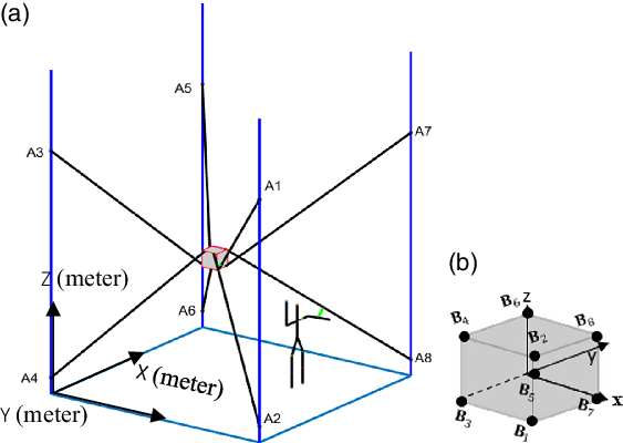
This paper presents a new method to detect and avoid collision between cables and human, while the trajectory of the end effector is unchanged and end effector tracks the trajectory inside the workspace. To perform this idea, a model of the interference between cables and human should be considered that is presented in Section 3.
3. Modeling the interference between cables and human
This section presents coordinate configuration and reconfiguration theory for the fully constrained CDPM. Modelling analysis of CDPM by symbolically establishing the coordinate system is then discussed. As a contribution to this paper, a new method based on the KKT condition to compute the distance between all cables and human limbs is proposed. Finally, the relocation of corresponding attachment points on the fixed frame is presented.
3.1 Coordinate system and attachment points
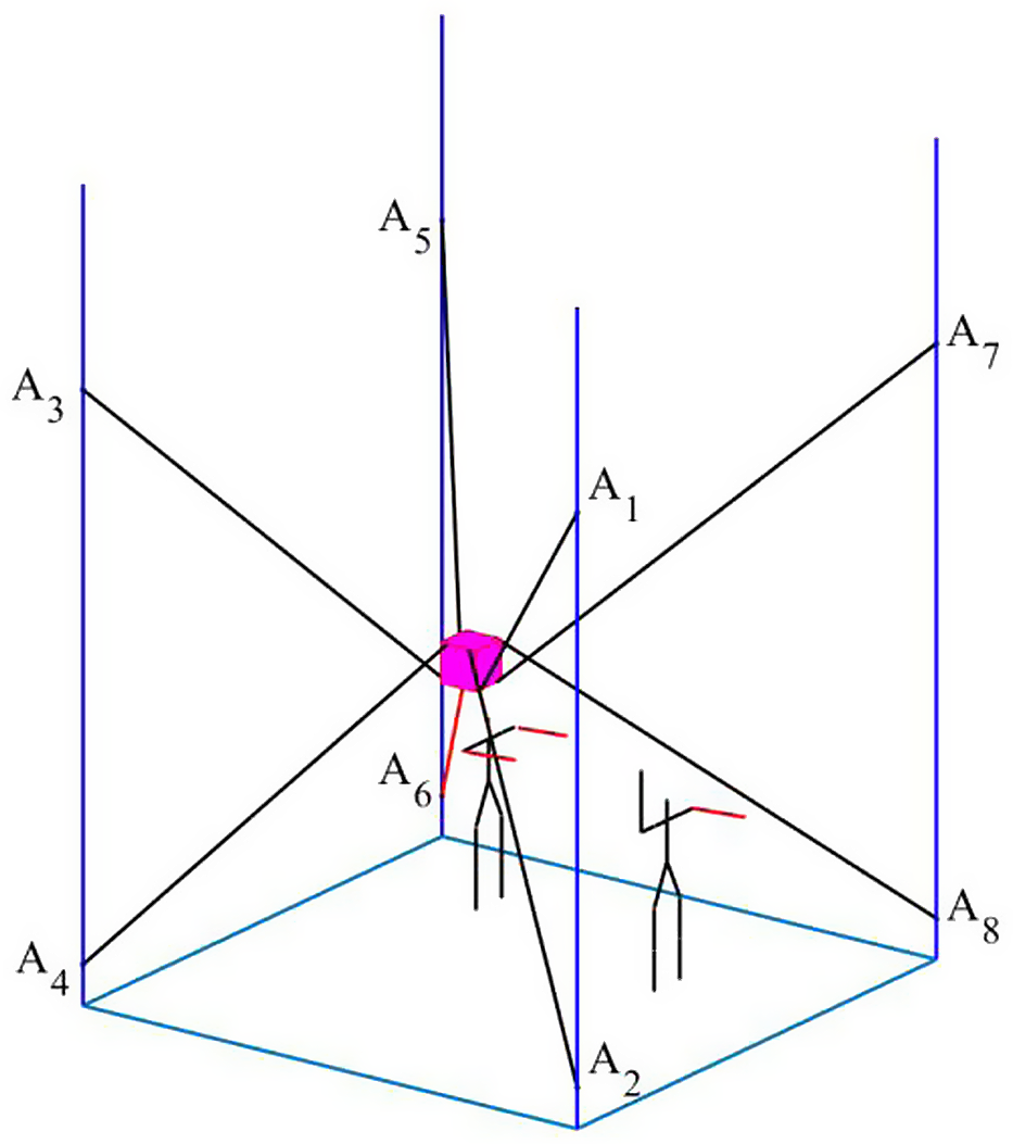
In this study, a fixed global frame (X–Y–Z) can be seen in Fig. 1, at the bottom left corner, and the Z axis direction is vertically upward, and the X–Y axes can be found according to right-hand rule. Whereas the attachment points on the rails are fixed in conventional CDPM, to avoid collision, our approach moves up/down the cable attachment points on the rail (reel location) in order to increase the distance between the human with cables to the safest threshold as suggested in ref. [Reference Haddadin, Albu-Schäffer and Hirzinger50]. As it can be observed in Fig. 1, servo-actuated reels are connected to the moving platform with eight cables to get a fully constrained CDPM in the six DOFs. Each cable is connected to the end effector at points $\mathbf{B}_{i}$
. To relocate the attachment points on rails
$\mathbf{B}_{i}$
. To relocate the attachment points on rails $\mathbf{A}_{i}$
, equations are obtained to find the desired cable length to reach a given end effector position and orientation. Suggested configuration is used to detect distance between cables and human and to obtain new position of attachment points on rails while keeping the end effector trajectory unchanged. In this research, the cables are considered massless and straight lines.
$\mathbf{A}_{i}$
, equations are obtained to find the desired cable length to reach a given end effector position and orientation. Suggested configuration is used to detect distance between cables and human and to obtain new position of attachment points on rails while keeping the end effector trajectory unchanged. In this research, the cables are considered massless and straight lines.
To verify the performance of the presented approach to avoid collision between cables and a human in the shared workspace, a human skeleton is inserted through a colliding distance with cables in simulation where the end effector performs its trajectories for its production tasks.
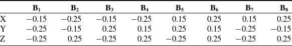
There are eight attachment points ( $\mathbf{B}_{i}$
) on the end effector (rectangular prism shape). The dimensions of the end effector are 0.5 × 0.5 × 0.5
$\mathbf{B}_{i}$
) on the end effector (rectangular prism shape). The dimensions of the end effector are 0.5 × 0.5 × 0.5 $\mathrm{m}^{3}$
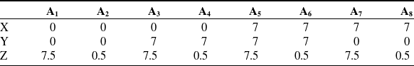
. The location of attachment points (
A
i) on the base and the locations of the attachment points (
$\mathrm{m}^{3}$
. The location of attachment points (
A
i) on the base and the locations of the attachment points ( $\mathbf{B}_{i}$
) on the end effector with respect to the local frame (
$\mathbf{B}_{i}$
) on the end effector with respect to the local frame ( $\varepsilon$
in meters) are observed respectively in Table I and Table II.
$\varepsilon$
in meters) are observed respectively in Table I and Table II.
Initial positions of the eight attachment points (m).
Local positions of the eight attachment points (m).
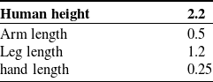
The human limbs length and human height are presented in Table III.
Human limbs length (m).
Kinematic and driving constraints are discussed in Sections 3.2 and 3.3. These constraints should be considered to evaluate forward and inverse kinematics. Kinematic constraint restricts moving attachment points only in vertical direction.
3.2 Kinematics constraints
The generalized coordinates of the system or $\vec {\mathbf{q}}$
consisting of
$\vec {\mathbf{q}}$
consisting of $\vec {\mathbf{q}}_{ac}$
and
$\vec {\mathbf{q}}_{ac}$
and $\vec {\mathbf{q}}_{er}$
are presented in (1):
$\vec {\mathbf{q}}_{er}$
are presented in (1):
(a) $\vec {\mathbf{q}}_{ac}$
is defined as generalized coordinates of the attachment points on the rail.
$\vec {\mathbf{q}}_{ac}$
is defined as generalized coordinates of the attachment points on the rail.
(b) $\vec {\mathbf{q}}_{er}$
is defined as generalized coordinates of the attachment points on the end effector.
$\vec {\mathbf{q}}_{er}$
is defined as generalized coordinates of the attachment points on the end effector.
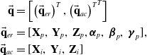 \begin{align} \vec {\mathbf{q}}& =\left[\left({\vec {\mathbf{q}}_{er}}\right)^{T}, {\left({\vec {\mathbf{q}}_{ac}}\right)^{T}}^{T}\right] \nonumber \\ \vec{\mathbf{q}}_{er} & = [\textbf{X}_{p},\,\textbf{Y}_{p},\,\textbf{Z}_{p},\boldsymbol\alpha_{p},\,\boldsymbol\beta_{p},\,\boldsymbol\gamma_{p}], \nonumber \\ \vec{\mathbf{q}}_{ac} &= [\textbf{X}_{i},\,\textbf{Y}_{i},\,\textbf{Z}_{i}] \end{align}
In this project, the movement in vertical direction is limited for each attachment points. Kinematic constraints for moving in X and Y directions have been restricted as follows [Reference Youssef and Otis29]:
 \begin{equation} \left[\begin{array}{c} \mathbf{x}_{i}\\[5pt] \mathbf{y}_{i} \end{array}\right]=\left(\begin{array}{c} \mathbf{k}_{i}^{1}\\[5pt] \mathbf{k}_{i}^{2} \end{array}\right)i=1\;to\;n \end{equation}
Cartesian coordinates of attachment points on reels in the global coordinate system are indicated by $\mathbf{x}_{i}$
and
$\mathbf{x}_{i}$
and $\mathbf{y}_{i}$
.
$\mathbf{y}_{i}$
. $\mathbf{k}_{i}$
is a constant and indicates attachment points position with respect to the fixed frame.
$\mathbf{k}_{i}$
is a constant and indicates attachment points position with respect to the fixed frame.
3.3 Driving constraints
The driving constraints are introduced as defined motion trajectories. In this project, three groups of driving constraints are considered.
-
a. The first group of driving constraints, due to the vertical motion of the eight attachment points on the rails, is presented in (3) as suggested in ref. [Reference Youssef and Otis29]:
(3)where \begin{equation} \mathbf{z}_{i}=\mathbf{c}_{i}\left(t,\vec {\mathbf{q}}\right)\text{for }i=1\;\text{to}\;\mathrm{n}, \end{equation}
$\mathbf{z}_{i}$
is defined as Z coordinate of each reel on the rails and
$\mathbf{c}_{i}\left(t,\vec {\mathbf{q}}\right)$
is a function to drive the attachment point vertically. Also, this function should depend on
$t$
(time),
$\vec {\mathbf{q}}$
(generalized coordinates), human limbs velocity, and sampling frequency for example.
\begin{equation} \mathbf{z}_{i}=\mathbf{c}_{i}\left(t,\vec {\mathbf{q}}\right)\text{for }i=1\;\text{to}\;\mathrm{n}, \end{equation}
$\mathbf{z}_{i}$
is defined as Z coordinate of each reel on the rails and
$\mathbf{c}_{i}\left(t,\vec {\mathbf{q}}\right)$
is a function to drive the attachment point vertically. Also, this function should depend on
$t$
(time),
$\vec {\mathbf{q}}$
(generalized coordinates), human limbs velocity, and sampling frequency for example.
For this research work, this value is fixed as a constant. Therefore, each attachment point can move vertically 0.1 m up and down in simulation as explained in Section 3.6.


-
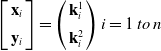
b. The second group of driving constraints can be introduced due to the extension and retraction of each cable attached to the end effector. It is indicated by changing the length of cables. The length of the cable can be defined by hypotenuse of a right-angle triangle by the vertices
$\mathbf{A}_{1}$
,
$\mathbf{B}_{1}$
, and
$\mathbf{B}_{1Z}$
. As can be seen in Fig. 2, these equations of second group constraint are presented as follows:


 \begin{equation} \left({{\mathbf{B}_{x}}}\right)_{i}^{2}+\left({{\mathbf{B}_{y}}}\right)_{i}^{2}+\left({\mathbf{A}_{i}}-\left({{\mathbf{B}_{z}}}\right)_{i}\right)^{2}=\mathbf{p}_{i}^{2}\,\,\,\text{for }i=1\;\text{to}\;\mathrm{n} \end{equation}
-
c. The third group of driving constraints in this paper is workspace analysis. Workspace analysis of CDPM is the ability of the end effector to translate or orient under some constraints. Five workspace categories are introduced: static equilibrium workspace, WCW, feasible wrench workspace, dynamic workspace, and collision-free workspace [Reference Duan and Duan51]. The feasible wrench workspace is presented as all possible positions and orientations of the end effector while maintaining a positive tension among all the cables. Set of positive tension vector in all the cables maintain each set of external wrenches acting on the end effector. The feasible wrench workspace is presented as follows:
(5)
\begin{equation}\tilde{\mathrm{w}}\vec {\mathbf{t}}+\vec {\mathbf{w}_{J}}=\vec {\mathbf{0}_{6}}\quad \mathrm{t}_{min}\lt \vec {\mathbf{t}}\lt \mathrm{t}_{max}\;\text{ and }\tilde{\mathrm{w}}=\left[\begin{array}{c@{\quad}c@{\quad}c} \vec {u_{1}} & \ldots & \vec {u_{8}}\\[5pt] \vec {r_{1}}\vec {u_{1}} & \ldots & \vec {r_{8}}\vec {u_{8}} \end{array}\right] \end{equation}
$\vec {\mathbf{w}_{J}}$
or external wrench acting on the end effector is weight of the end effector as 25 n in the Z direction.
$\tilde{\mathrm{w}}$
and
$\vec {\mathbf{t}}$
are structure matrix and tension in the cables, respectively. The two variables (
$\vec {r_{i}}$
and
$\vec {u_{i}}$
) in the structure matrix
$\tilde{\mathrm{w}}$
are explicit functions in the position and orientation of the end effector as well as the attachments points position. The tension of each cable is positive value, and it is between minimum tension
$\mathrm{t}_{min}$
= 20 and maximum tension
$\mathrm{t}_{max}$
= 90 n [Reference Youssef and Otis29].


Second group of driving constraints [Reference Youssef and Otis29].
Finally, the total constraint equations can be introduced as Eqs. (2) to (5). The next section presents the algorithm to solve the forward and inverse kinematics using these constraints.
3.4 Forward and inverse kinematic of proposed reconfiguration theory
3.4.1 Forward kinematic
In conventional CDPM, the forward kinematics is used to manipulate and control the position and orientation of the end effector as output given the cable lengths. However, in the reconfigurable CDPM, the forward kinematic algorithm is evaluated to compute cartesian coordinates of the reference frame of the end effector given the linear displacement of attachment points on rails $\mathbf{c}_{i}\left(t,\vec {\mathbf{q}}\right)$
and the eight cable lengths as inputs [Reference Youssef and Otis29].The Levenberg–Marquardt least squares method [Reference Moré52] is used to solve the forward kinematics problem.
$\mathbf{c}_{i}\left(t,\vec {\mathbf{q}}\right)$
and the eight cable lengths as inputs [Reference Youssef and Otis29].The Levenberg–Marquardt least squares method [Reference Moré52] is used to solve the forward kinematics problem.
3.4.2 Inverse kinematic
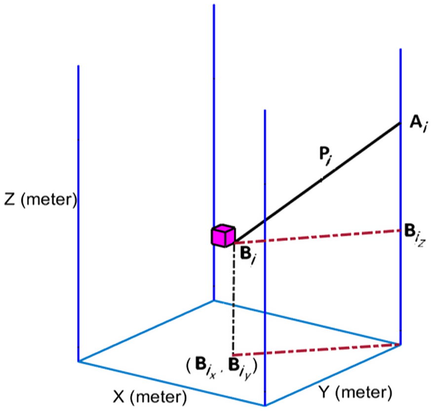
Figure 3 shows the schematic for the end effector and attachment points A
i, where O is the fixed global frame and $\varepsilon$
is a local frame attached to the end effector. This figure shows cable i and human limb as two-lines segments.
$\varepsilon$
is a local frame attached to the end effector. This figure shows cable i and human limb as two-lines segments.
Second group of driving constraints.
In the reconfigurable CDPM theory proposed in this paper, the inverse kinematics is defined as (5). Meanwhile, that variable inputs are introduced as the pose of the end effector and the attachment point’s location on the reels, and output is known as cable length. Regarding Fig. 3, the vector loop-closure equation or length of cables for cable i is introduced as follows:
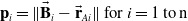 \begin{equation} \mathbf{p}_{i}=\| \vec {\mathbf{B}}_{i}-\vec {\mathbf{r}}_{Ai}\| \text{ for }i=1\;\text{to}\;\mathrm{n} \end{equation}
where (7) indicates the coordinates of point $\mathbf{B}_{i}$
as follows:
$\mathbf{B}_{i}$
as follows:
 \begin{equation} \vec {\mathbf{B}}_{i}=\vec {\mathbf{r}}_{ef}+\mathbf{R}\vec {\mathbf{r}}'_{\!\!i}\text{ for }i=1\;\text{to}\;\mathrm{n}\left(\text{number of cables}\right) \end{equation} $\vec {\mathbf{r}}_{ef}$
is the position vector of the center of mass of the end effector and R is introduced as rotation matrix of moving platform frame with respect to local frame.
$\vec {\mathbf{r}}_{ef}$
is the position vector of the center of mass of the end effector and R is introduced as rotation matrix of moving platform frame with respect to local frame. $\vec {\mathbf{r}}'_{\!\!i}$
is the local coordinate frame attached to the end effector
$\vec {\mathbf{r}}'_{\!\!i}$
is the local coordinate frame attached to the end effector $\varepsilon$
. Shortest distance computation can be used to detect collision between human and cables that is discussed in next section.
$\varepsilon$
. Shortest distance computation can be used to detect collision between human and cables that is discussed in next section.
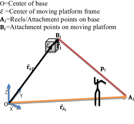
Vector formulation of the distance between limb and cables.
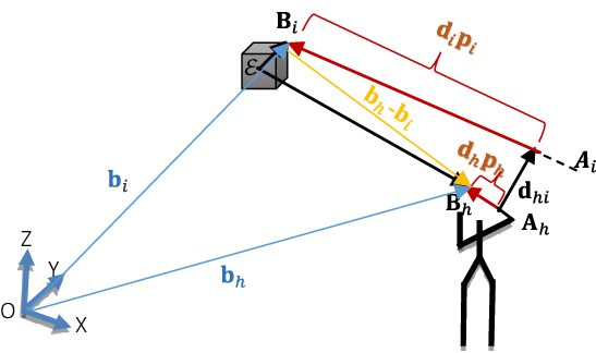
3.5 Shortest distance computation as collision detection between cables and human
Some formulations are introduced to define the interference contact points [Reference Otis, Nguyen-Dang, Laurendeau and Gosselin53]. One method is based on determining a line perpendicular to two lines to define the shortest distance. Whereas interference happens when the cables are coplanar, it is necessary to add a condition to recognize that an intersection occurs inside or outside the cable lengths. The shortest distance between cables can be geometrically computed as discussed in refs. [Reference Meziane, Cardou and Otis46] and [Reference Otis, Nguyen-Dang, Laurendeau and Gosselin53]. Two non-dimensional variables $\mathbf{d}_{h}$
and
$\mathbf{d}_{h}$
and $\mathbf{d}_{i}$
are introduced, where
$\mathbf{d}_{i}$
are introduced, where $\mathbf{d}_{i}\mathbf{p}_{i}$
and
$\mathbf{d}_{i}\mathbf{p}_{i}$
and $\mathbf{d}_{h}\mathbf{p}_{h }$
are illustrated by red lines in Fig. 4.
$\mathbf{d}_{h}\mathbf{p}_{h }$
are illustrated by red lines in Fig. 4. $\mathbf{A}_{i}\mathbf{B}_{i} \mathrm{and}$ $\mathbf{A}_{h}\mathbf{B}_{h}$
present the length of eight cables and human arm, respectively.
$\mathbf{A}_{h}\mathbf{B}_{h}$
present the length of eight cables and human arm, respectively. $\mathbf{d}_{i}\mathbf{p}_{i}$
is distance between
$\mathbf{d}_{i}\mathbf{p}_{i}$
is distance between $\mathbf{B}_{i}$
and the line that represents the shortest distance between cable and human.
$\mathbf{B}_{i}$
and the line that represents the shortest distance between cable and human. $\mathbf{d}_{h}\mathbf{p}_{h}$
is distance between
$\mathbf{d}_{h}\mathbf{p}_{h}$
is distance between $\mathbf{B}_{h}$
and the line that represents the shortest distance between cable and human. This new approach is used to avoid cables being parallel at infinity.
$\mathbf{B}_{h}$
and the line that represents the shortest distance between cable and human. This new approach is used to avoid cables being parallel at infinity. $\mathbf{d}_{hi}$
is introduced as a distance vector between cables and human as follows:
$\mathbf{d}_{hi}$
is introduced as a distance vector between cables and human as follows:
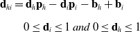 \begin{align} \mathbf{d}_{hi} & =\mathbf{d}_{h}\mathbf{p}_{h}-\mathbf{d}_{i}\mathbf{p}_{i}-\mathbf{b}_{h}+\mathbf{b}_{i} \nonumber \\[5pt] & \quad 0\leq \mathbf{d}_{i}\leq 1\;and\;0\leq \mathbf{d}_{h}\leq 1 \end{align} $\mathbf{d}_{h}$
and
$\mathbf{d}_{h}$
and $\mathbf{d}_{i}$
are coefficients of two cable lengths. The maximum length of cables is considered, when
$\mathbf{d}_{i}$
are coefficients of two cable lengths. The maximum length of cables is considered, when $\mathbf{d}_{h}$
and
$\mathbf{d}_{h}$
and $\mathbf{d}_{i}$
are in upper value or one. Nonlinear optimization method known as KKT conditions [Reference Taghirad and Bedoustani54, Reference Carricato and Merlet55] can guarantee the main goal to minimize the norm of
$\mathbf{d}_{i}$
are in upper value or one. Nonlinear optimization method known as KKT conditions [Reference Taghirad and Bedoustani54, Reference Carricato and Merlet55] can guarantee the main goal to minimize the norm of $\mathbf{d}_{hi}$
in (8) as a cost function. Several multipliers can solve the optimization problem by equality and inequality constraints. But in this paper, inequality constraints are considered. So, the problem is introduced as follows:
$\mathbf{d}_{hi}$
in (8) as a cost function. Several multipliers can solve the optimization problem by equality and inequality constraints. But in this paper, inequality constraints are considered. So, the problem is introduced as follows:
Minimise, $\parallel \mathbf{d}_{hi}\parallel _{2}$
Subject to:
 \begin{align} & -\mathbf{d}_{h}\leq 0 \nonumber \\[5pt] & \mathbf{d}_{h}-1\leq 0 \nonumber \\[5pt] &-\mathbf{d}_{i}\leq 0 \nonumber \\[5pt]& \mathbf{d}_{i}-1 \leq 0 \end{align}
The optimal values of the coefficients $\mathbf{d}_{h}$
and
$\mathbf{d}_{h}$
and $\mathbf{d}_{i}$
can help to find minimum distance. KKT theorem introduces the Lagrange multipliers, λ, with
$\mathbf{d}_{i}$
can help to find minimum distance. KKT theorem introduces the Lagrange multipliers, λ, with $\boldsymbol{\lambda }_{i}\geq 0$
and i = 1,…4, as each constraint [Reference Meziane, Cardou and Otis46]. The Lagrange function by inequality constraints is introduced as follows:
$\boldsymbol{\lambda }_{i}\geq 0$
and i = 1,…4, as each constraint [Reference Meziane, Cardou and Otis46]. The Lagrange function by inequality constraints is introduced as follows:
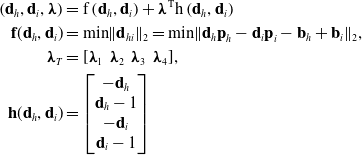 \begin{align} \left(\mathbf{d}_{h},\mathbf{d}_{i},\boldsymbol{\lambda }\right)&=\mathrm{f}\left(\mathbf{d}_{h},\mathbf{d}_{i}\right)+\boldsymbol{\lambda }^{\mathrm{T}}\mathrm{h}\left(\mathbf{d}_{h},\mathbf{d}_{i}\right) \nonumber \\ \textbf{f}(\textbf{d}_{h},\textbf{d}_{i}) & = \textrm{min} \|\textbf{d}_{hi}\|_{2} = \textrm{min} \|\textbf{d}_{h}\textbf{p}_{h}-\textbf{d}_{i}\textbf{p}_{i}-\textbf{b}_{h}+\textbf{b}_{i}\|_{2}, \nonumber \\ \boldsymbol{\lambda}_{T} &= [\boldsymbol{\lambda}_{1}\;\;\boldsymbol{\lambda}_{2}\;\;\boldsymbol{\lambda}_{3}\;\;\boldsymbol{\lambda}_{4}], \nonumber \\ \textbf{h}(\textbf{d}_{h},\textbf{d}_{i}) & = \left[\begin{matrix} -\textbf{d}_{h} \\ \textbf{d}_{h}-1 \\ -\textbf{d}_{i} \\ \textbf{d}_{i}-1 \end{matrix}\right] \end{align}
Meziane et al. [Reference Meziane, Cardou and Otis46] introduced the simplified equation with all conditions and cases. Different $\mathbf{d}_{h}$
and
$\mathbf{d}_{h}$
and $\mathbf{d}_{i}$
can be generated while Lagrange multipliers are activated and deactivated. However,
$\mathbf{d}_{i}$
can be generated while Lagrange multipliers are activated and deactivated. However, $\boldsymbol{\lambda }_{1}$
and
$\boldsymbol{\lambda }_{1}$
and $\boldsymbol{\lambda }_{2}$
or
$\boldsymbol{\lambda }_{2}$
or $\boldsymbol{\lambda }_{3}$
and
$\boldsymbol{\lambda }_{3}$
and $\boldsymbol{\lambda }_{4}$
could not be activated simultaneously, since
$\boldsymbol{\lambda }_{4}$
could not be activated simultaneously, since $\mathbf{d}_{h}$
(or
$\mathbf{d}_{h}$
(or $\mathbf{d}_{i}$
) cannot accept two values. Some cases are not acceptable when
$\mathbf{d}_{i}$
) cannot accept two values. Some cases are not acceptable when $\mathbf{d}_{i}$
is at the upper limit of the inequality constraint. In this situation, the lengths of cables are in high position; therefore, there is no collision between human and cables. But when
$\mathbf{d}_{i}$
is at the upper limit of the inequality constraint. In this situation, the lengths of cables are in high position; therefore, there is no collision between human and cables. But when $\mathbf{d}_{i}$
is at the lower limit of the inequality constraint or free, the collision between the human and the cables could be occurring. Six cases are introduced as follows:
$\mathbf{d}_{i}$
is at the lower limit of the inequality constraint or free, the collision between the human and the cables could be occurring. Six cases are introduced as follows:
Case 1: $\mathbf{d}_{h}$
and
$\mathbf{d}_{h}$
and $\mathbf{d}_{i}$
are found by the inequality constraints. Indeed,
$\mathbf{d}_{i}$
are found by the inequality constraints. Indeed, $0\leq \mathbf{d}_{h}\leq 1$
and
$0\leq \mathbf{d}_{h}\leq 1$
and $0\leq \mathbf{d}_{i}\leq 1$
. The Lagrange multipliers are free
$0\leq \mathbf{d}_{i}\leq 1$
. The Lagrange multipliers are free $\boldsymbol{\lambda }_{h}$
= 0. So, (10) can be observed as follows.
$\boldsymbol{\lambda }_{h}$
= 0. So, (10) can be observed as follows.
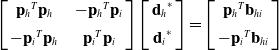 \begin{equation} \left[\begin{array}{c@{\quad}c} {\mathbf{p}_{h}}^{T}\mathbf{p}_{h} & {-\mathbf{p}_{h}}^{T}\mathbf{p}_{i}\\[5pt] {-\mathbf{p}_{i}}^{T}\mathbf{p}_{h} & {\mathbf{p}_{i}}^{T}\mathbf{p}_{i} \end{array}\right] \left[\begin{array}{c} {\mathbf{d}_{h}}^{*}\\[5pt] {\mathbf{d}_{i}}^{*} \end{array}\right]=\left[\begin{array}{c} {\mathbf{p}_{h}}^{T}\mathbf{b}_{hi}\\[5pt] {-\mathbf{p}_{i}}^{T}\mathbf{b}_{hi} \end{array}\right] \end{equation}
while $\colon \mathbf{b}_{hi}=\mathbf{b}_{h}-\mathbf{b}_{i}$
Case 2: $\mathbf{d}_{i}$
is located at the lower limit of the inequality constraint and
$\mathbf{d}_{i}$
is located at the lower limit of the inequality constraint and $\mathbf{d}_{h}$
is free. Therefore,
$\mathbf{d}_{h}$
is free. Therefore, $\boldsymbol{\lambda }_{3}=1$
is active, and
$\boldsymbol{\lambda }_{3}=1$
is active, and $\boldsymbol{\lambda }_{1}=\boldsymbol{\lambda }_{2}=0$
deactivated as well
$\boldsymbol{\lambda }_{1}=\boldsymbol{\lambda }_{2}=0$
deactivated as well $\boldsymbol{\lambda }_{4}=0$
.
$\boldsymbol{\lambda }_{4}=0$
.
 \begin{align} \begin{cases} {\mathbf{d}_{h}}^{\boldsymbol{*}}=\dfrac{{p_{h}}^{T}b_{hi}}{{p_{h}}^{T}p_{h}}\\[9pt] {\mathbf{d}_{i}}^{\boldsymbol{*}}=0 \end{cases} \end{align}
Case 3: $\mathbf{d}_{h}$
is the upper limit of the inequality constraint and
$\mathbf{d}_{h}$
is the upper limit of the inequality constraint and $\mathbf{d}_{i}$
is free. So,
$\mathbf{d}_{i}$
is free. So, $\boldsymbol{\lambda }_{2}$
= 1 is active and
$\boldsymbol{\lambda }_{2}$
= 1 is active and $\boldsymbol{\lambda }_{3}=\boldsymbol{\lambda }_{4}=0$
deactivated.
$\boldsymbol{\lambda }_{3}=\boldsymbol{\lambda }_{4}=0$
deactivated.
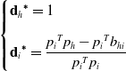 \begin{align} \begin{cases} {\mathbf{d}_{h}}^{\boldsymbol{*}}=1\\[9pt] {\mathbf{d}_{i}}^{\boldsymbol{*}}=\dfrac{{p_{i}}^{T}p_{h}-{p_{i}}^{T}b_{hi}}{{p_{i}}^{T}p_{i}} \end{cases} \end{align}
Case 4: when $\mathbf{d}_{h}$
is located at the lower limit of the inequality constraint and
$\mathbf{d}_{h}$
is located at the lower limit of the inequality constraint and $\mathbf{d}_{i}$
is free, so
$\mathbf{d}_{i}$
is free, so $\boldsymbol{\lambda }_{\mathbf{1}}$
= 1 is active and
$\boldsymbol{\lambda }_{\mathbf{1}}$
= 1 is active and $\boldsymbol{\lambda }_{3}$
=
$\boldsymbol{\lambda }_{3}$
= $\boldsymbol{\lambda }_{4}$
=
$\boldsymbol{\lambda }_{4}$
= $\boldsymbol{\lambda }_{2}$
= 0 is deactivated.
$\boldsymbol{\lambda }_{2}$
= 0 is deactivated.
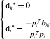 \begin{align} \begin{cases} {\mathbf{d}_{h}}^{\boldsymbol{*}}=0\\[9pt] {\mathbf{d}_{i}}^{\boldsymbol{*}}=\dfrac{-{p_{i}}^{T}b_{hi}}{{p_{i}}^{T}p_{i}} \end{cases} \end{align}
Case 5: $\mathbf{d}_{h}$
is at the upper limit of the inequality constraint and
$\mathbf{d}_{h}$
is at the upper limit of the inequality constraint and $\mathbf{d}_{i}$
is at the lower limit. Indeed
$\mathbf{d}_{i}$
is at the lower limit. Indeed $\boldsymbol{\lambda }_{\mathbf{1}}=1, \boldsymbol{\lambda }_{4}=1$
are active, and
$\boldsymbol{\lambda }_{\mathbf{1}}=1, \boldsymbol{\lambda }_{4}=1$
are active, and $\boldsymbol{\lambda }_{2}$
=
$\boldsymbol{\lambda }_{2}$
= $\boldsymbol{\lambda }_{3}$
= 0 is deactivated.
$\boldsymbol{\lambda }_{3}$
= 0 is deactivated.
 \begin{equation} \begin{cases} {\mathbf{d}_{h}}^{\boldsymbol{*}}=1\\[5pt] {\mathbf{d}_{i}}^{\boldsymbol{*}}=0 \end{cases} \end{equation}
Case 6: $\mathbf{d}_{h}$
and
$\mathbf{d}_{h}$
and $\mathbf{d}_{i}$
are located at the lower limit of the constraints.
$\mathbf{d}_{i}$
are located at the lower limit of the constraints. $\boldsymbol{\lambda }_{1}=\boldsymbol{\lambda }_{3}=1$
is activated and
$\boldsymbol{\lambda }_{1}=\boldsymbol{\lambda }_{3}=1$
is activated and $\boldsymbol{\lambda }_{2}=\boldsymbol{\lambda }_{4}=0$
is deactivated.
$\boldsymbol{\lambda }_{2}=\boldsymbol{\lambda }_{4}=0$
is deactivated.
 \begin{equation} \begin{cases} {\mathbf{d}_{h}}^{\boldsymbol{*}}=0\\[5pt] {\mathbf{d}_{i}}^{\boldsymbol{*}}=0 \end{cases} \end{equation}
Cable–human collision can be considered as two-line interference. A collision is detected when two lines get close to each other to a certain threshold value.
The next step is computation of $\mathbf{d}_{hi}$
for each value
$\mathbf{d}_{hi}$
for each value $\mathbf{d}_{h}$
and
$\mathbf{d}_{h}$
and $\mathbf{d}_{i}$
. The distance
$\mathbf{d}_{i}$
. The distance $\mathbf{d}_{hi}$
are the distance between the two points
$\mathbf{d}_{hi}$
are the distance between the two points $\mathbf{B}_{h}$
and
$\mathbf{B}_{h}$
and $\mathbf{B}_{i}$
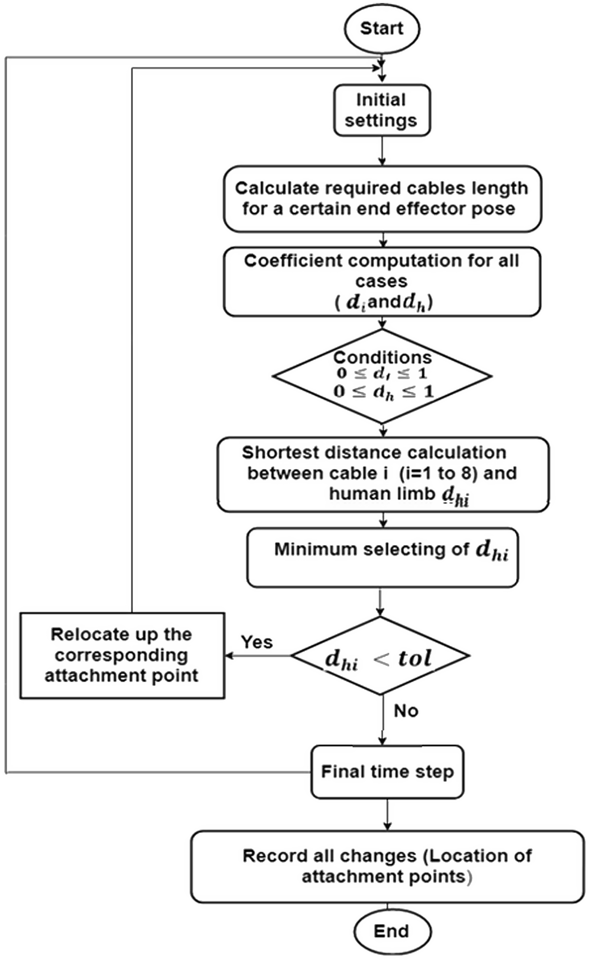
. The algorithm for the computation of the shortest distance between human and cables can be seen in Fig. 5. The first cable is selected, then coefficients for all six cases can be determined. In this case where the constraints are satisfied, the shortest distance according to (8) is then estimated. Hence, the computed shortest distance is compared with a threshold value such that the shortest distance value is increased by relocating vertically up and down the corresponding attachment point until the shortest distance between cables and human exceeds the threshold value, which means that the collision has been avoided, as it is discussed in later sections. The relocation theory of attachment points is discussed in the next section.
$\mathbf{B}_{i}$
. The algorithm for the computation of the shortest distance between human and cables can be seen in Fig. 5. The first cable is selected, then coefficients for all six cases can be determined. In this case where the constraints are satisfied, the shortest distance according to (8) is then estimated. Hence, the computed shortest distance is compared with a threshold value such that the shortest distance value is increased by relocating vertically up and down the corresponding attachment point until the shortest distance between cables and human exceeds the threshold value, which means that the collision has been avoided, as it is discussed in later sections. The relocation theory of attachment points is discussed in the next section.
Collision avoidance algorithm.
3.6. Cable interference avoidance – relocation of corresponding attachment points
After solving the inverse kinematics and the computation of the shortest distance between human and cables, the attachment points on the rails are relocating to solve the collision between cables and human while maintaining the end effector trajectory.
The shortest distance computation between human and cables depends on position of the human arm and the cables that can be found according to position of the attachment points on reels and the attachment points on end effector. In case of a near collision between human and cable $i$
(
$i$
( $i$
= 1 to 8), the reel moves up or down when
$i$
= 1 to 8), the reel moves up or down when $\mathbf{d}_{hi}$
is lower than threshold. Therefore, the position of the reel
$\mathbf{d}_{hi}$
is lower than threshold. Therefore, the position of the reel $i$
on the rail is displaced by a step as scalar
$i$
on the rail is displaced by a step as scalar $\Delta \mathrm{q}$
. Parameter
$\Delta \mathrm{q}$
. Parameter $\Delta \mathrm{q}$
is fixed at 1.5% of the distance between two attachment points on the one rail in Z direction. In this research, parameter
$\Delta \mathrm{q}$
is fixed at 1.5% of the distance between two attachment points on the one rail in Z direction. In this research, parameter $\Delta \mathrm{q}$
is selected theoretically 0.1 m. So, the new location of the attachment point
$\Delta \mathrm{q}$
is selected theoretically 0.1 m. So, the new location of the attachment point $\left(\vec {\mathbf{q}}_{{i_{z}}}\right)_{k+1}$
or
$\left(\vec {\mathbf{q}}_{{i_{z}}}\right)_{k+1}$
or $\left(\vec {\mathbf{q}}_{{i_{z}}}\right)_{new}$
is updated as follows: where the previous location of the attachment point
$\left(\vec {\mathbf{q}}_{{i_{z}}}\right)_{new}$
is updated as follows: where the previous location of the attachment point $\left(\vec {\mathbf{q}}_{{i_{z}}}\right)_{initial}$
or
$\left(\vec {\mathbf{q}}_{{i_{z}}}\right)_{initial}$
or $\left(\vec {\mathbf{q}}_{{i_{z}}}\right)_{k}$
moves as
$\left(\vec {\mathbf{q}}_{{i_{z}}}\right)_{k}$
moves as $\Delta \mathrm{q}$
on the rail:
$\Delta \mathrm{q}$
on the rail:
 \begin{equation}\left(\vec {\mathbf{q}}_{{i_{z}}}\right)_{k+1}=\left(\vec {\mathbf{q}}_{{i_{z}}}\right)_{k}+\Delta \mathrm{q}, \left(\vec {\mathbf{q}}_{{i_{z}}}\right)_{k}=\left(z_{i}\right)_{k}\end{equation}
k: actual sampling time
k + 1: next sampling time $z_{i}$
: position of attachment points in Z direction on the rail
$z_{i}$
: position of attachment points in Z direction on the rail
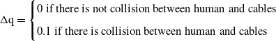 \begin{align*} \Delta \mathrm{q}=\begin{cases} 0\text{ if }\text{there is not collision between human and cables}\\[5pt] 0.1\text{ if }\text{there is collision between human and cables } \end{cases} \end{align*}
This theory can be valid by constraining the maximum vertical location of a reel on the rail where the attachment point should not overpass. The location of the reel can move vertically by a servo linear actuator. This idea of reconfiguration to avoid collision between cables and human limb simulated in Matlab is presented in Section 4.
4. Simulation of shortest distance cable–human collision avoidance
Relocation of the attachment points on the rails to avoid a collision between cables and humans is this project’s main goal. Matlab script is used to detect and eliminate cable–human interference in simulation.
In Sections 4.1, three positions (close to cables 8, 6, and 2) are selected to perform the presented algorithm when human is placed in different parts of the workspace. The algorithm avoids collision between human limbs and cables while the end effector keeps the trajectory unchanged, as shown in supplementary material, Video 1: (Experiment 1: One human in the workspace) [Reference Khoshbin, Youssef, Meziane and Otis56]. A simple inverse kinematics approach is used regarding the predefined trajectory and position of attachment points. Section 4.2 presents the feasible wrench workspace when a human is located near cables 8, 6, and 2, as shown in supplementary material, Video 1: (Experiment 1: One human in the workspace) [Reference Khoshbin, Youssef, Meziane and Otis56]. To show the ability of the algorithm to avoid collision between humans and cables, two or more humans are added to the workspace in Section 4.3, as shown in supplementary material, Video 2: Experiment 2 (Two humans in the workspace) [Reference Khoshbin, Youssef, Meziane and Otis57]. The 3D view of the one human is shown in Fig. 1. Two humans in the shared workspace are indicated in 3D, as shown in Fig. 6.
Two humans in shared workspace.
The method presented in this paper can be applied to three-dimensional objects. Whereas each 3D geometry can be represented by triangle mesh which comprises a set of triangles (connected by their edges), the 3D model of whole human body or other obstacles can be used for this suggested method.
Regarding the trajectory computation point, simple inverse kinematics approach is used, where the trajectory is defined previously. The number of AFLO (Algorithm FLoating-point Operation) of the code in Matlab is estimated at 278 for four functions inside the algorithm presented in Fig. 5. This algorithm is presented as follows (for each iteration):
-
1. Shortest distance computation between human and each cable with 147 AFLO
-
2. Collision avoidance algorithm with 11 AFLO
-
3. Cable length computation for each iteration with 24 AFLO
-
4. Cable tension computation for each iteration with 96 AFLO
An iteration corresponds to an update of the setpoint of the tensile force and pose which are submitted to the robot closed-loop controller. Meanwhile, capacity in GFLOPS of the computer [Reference Issa58] is 161, while the sampling period is 1 msec. The total execution time of the suggested algorithm is estimated at 1.72670807e-9 which is less than 70% sampling time 1.72670807e-9 $\lt$
0.007. The execution time is evaluated using this equation:
$\lt$
0.007. The execution time is evaluated using this equation:
 \begin{equation}\text{Execution time }=\frac{\mathbf{AFLO}\left(\mathbf{A}\text{lgorithm}\;\mathbf{FL}\text{oating point}\; \mathbf{O}\text{peration}\right)\text{in the algorithm }}{\text{Capacity in FLOPS of the computer}}\end{equation}
The capacity of the computer is evaluated using Linepack Xtreme x64 for Windows which estimates the number of FLOPS. The number of floating-point operations of the suggested algorithm (AFLO) is estimated using ref. [Reference Qian59]. In hard real-time application, the overall algorithm has to be less than 70% of the sampling period. Although, there is currently no physical model of the robot, it is possible to state that the suggested algorithm can operate in real time in the presence of a physical model of a cable-driven parallel robot.
Section 4 .1 discusses the results of collision avoidance between one human and two humans with cables in shared workspace.
4.1 Results
The presented method can determine the shortest distance as collision detection. If the shortest distance is lower than tolerance and close to collision, the algorithm moves the attachment point on rails and updates the cable lengths. The results of the shortest distance between cables and human can be seen in Fig. 7 for three situations when human is close to cables 8, cable 2, and cable 6 for circular trajectory. The end effector tracks the circular trajectory (as the desired trajectory) presented by Youssef and Otis [Reference Youssef and Otis29]. To guarantee human safety, the threshold between human and cable is considered as 0.35 m.
Shortest distance between cables and human near cable 8 (circular trajectory).
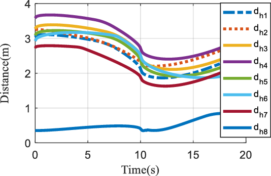
As shown in Fig. 7 when human is near cable 8, all cables except cable 8 are at acceptable distance from human limb. The distance between human near cable 8 and cables are $\mathbf{d}_{{h_{i}}}.$
It can be observed that the distance between cable 8 and human is less than threshold, and the position of cable 8 needs to be modified to avoid cable–human collision. Therefore, Fig. 8 shows that there is no change in the position of reels 1 to 7. The reels 2,4, and 6 are located at 0.5 m, and the reels 1, 3, 5, and 7 are located at 7.5 m.
$\mathbf{d}_{{h_{i}}}.$
It can be observed that the distance between cable 8 and human is less than threshold, and the position of cable 8 needs to be modified to avoid cable–human collision. Therefore, Fig. 8 shows that there is no change in the position of reels 1 to 7. The reels 2,4, and 6 are located at 0.5 m, and the reels 1, 3, 5, and 7 are located at 7.5 m.
Attachment point location of cables 1 to 7 – human near cable 8.
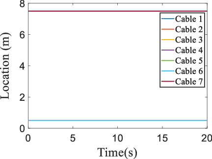
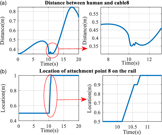
Figure 9 demonstrates the shortest distance between cable 8 and human and the relocation of attachment point 8. When the shortest distance between human and cable 8 falls below the threshold, detected by an algorithm at around 10 s, the relocation of attachment points on reels could avoid collision between cable 8 and the human limb. So, the distance is increased until the distance between cable 8 and human reaches a reliable distance and above the threshold.
Circular trajectory: (a) shortest distance between cable 8 and human (human is placed near cable 8) and (b) attachment point location of cable 8.
To investigate the performance of the proposed method, the results have been obtained when human is close to cable 2 and cable 6. Figure 10(b-1) shows the distance between human and cable 2 when human is located close to cable 2 and Figure 10(a-1) indicates the distance between human and cable 6 when human is placed near cable 6. There are four points that distance between human and cable 6 is in threshold, and three threshold points in distance between human and cable 2 can be seen in Fig. 10(b-2).
Circular trajectory: (a-1) distance between human and cable 6 (human is located close to cable 6), (a-2) attachment point position of cable 6 on the rail, (b-1) distance between human and cable 2 (human is located close to cable 2), and (b-2) attachment point position of cable 2 on the rail.
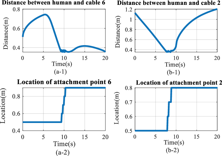
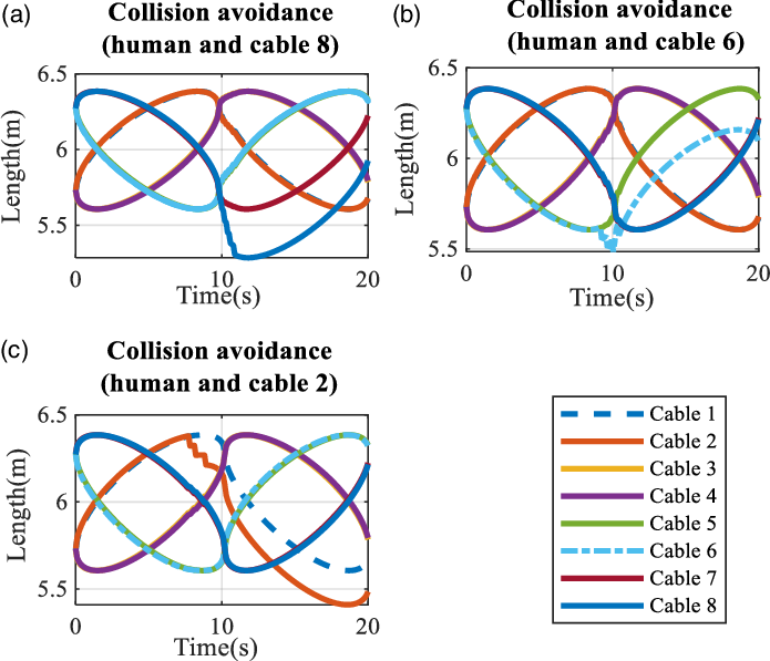
Figure 11 indicates the length of cables for all three situations. According to Fig. 11, there are changes suddenly in length of cables because of close distance between cable 8 and skeleton placed near cable 8 in Fig. 11(a), between human and cable 6 in Fig. 11(b) when human model is located near cable 6 and between human and cable 2 in Fig. 11(c).
Length of cables (circular trajectory): (a) human near cable 8, (b) human near cable 6, and (c) human near cable 2.
4.2 The wrench feasible workspace
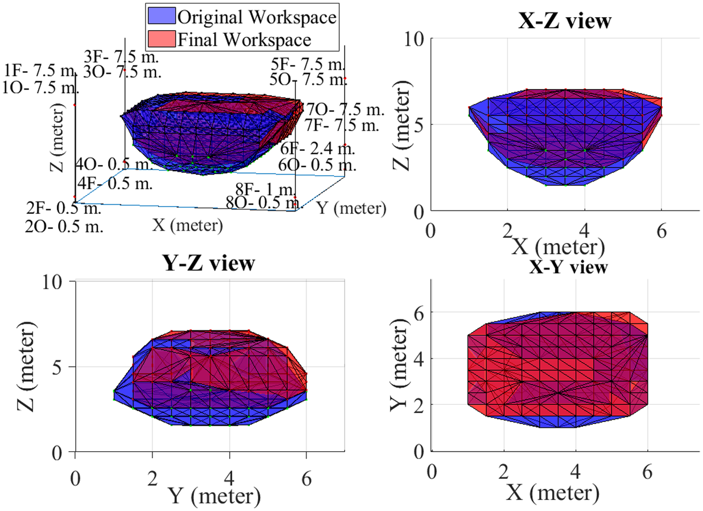
Firstly, cables tension distribution equation can be solved to map feasible workspace. The computational algorithm is used to map the reconfigurable workspace. Figure 12 indicates the initial (blue) and final (red) workspaces according to the reconfiguration of the mechanism due to circular motion of end effector and distance between human arm and cable 2, 6, and 8.
Circular trajectory (cables–human collision when human is near cable 8): (a) final and original workspaces 3D, (b) front view, (c) side view, and (d) top view.

As it can be observed in Fig. 12, final workspace is changed due to relocation of the attachment points on the rail, while trajectory of the end effector kept unchanged. Upper attachment points (1, 3, 5, and 7) are located Initially at 7.5 m. In Fig. 13, cable 8 was initially at 0.5 m and is moving to 1 m to avoid collision when human is located near cable 8. As can be seen in Fig. 12(a), the top part of the final workspace and the initial workspace are same. This can be clearly observed by comparing between the X–Z views Fig. 12(b). Meanwhile, there was no noteworthy change by comparing initial and final workspace the X–Y views (Fig. 12(d)) or the Y–Z views Fig. (12 c). The results for two other situations are observed in Figs. 13 and 14. The attachment point 2 in Fig. 13(b) is moved from 0.5 to 0.8 m. This movement could prove Fig. 12 where five points in threshold distance is observed. Also, Fig. 14(c) indicates initial and final workspaces when human is near cable 6; meanwhile, the attachment point 6 can be moved from 0.5 to 0.9 m in order to avoid collision between human and cable 6.
Circular trajectory (cables–human collision when human is near cable 2): (a) final and original workspaces 3D, (b) front view, (c) side view, and (d) top view.

Circular trajectory (cables–human collision when human is near cable 6): (a) final and original workspaces 3D, (b) front view, (c) side view, and (d) top view.

Figures 15, 16, and 17 indicate the difference between original and final workspaces and are presented by the boundary of some points of the end effector’s position in an original workspace that cannot be found in the final workspace. As can be seen in Figs. 15, 16, and 17, the final workspace is strictly smaller at the bottom part due to a change in the position of the attachment points on rails 8, 6, and 2. The position of the upper attachment points does not change in the initial and final workspace, and the final trajectory is inside the initial workspace.
Difference between original and final workspaces when human is near cable 8: (a) difference between final and original workspace 3D, (b) front view, (c) side view, and (d) top view.

Difference between original and final workspaces when human is near cable 2: (a) difference between final and original workspace 3D, (b) front view, (c) side view, and (d) top view.

Difference between original and final workspaces when human is near cable 6: (a) difference between final and original workspace 3D, (b) front view, (c) side view, and (d) top view.

4.3 Two humans inside the workspace
The risk of collision between humans and robots could be raised when many humans are in the workspace. The suggested algorithm can avoid collision between all humans and each cable. In addition of collision avoidance between one human and cables, collision avoidance between two humans located in the hybrid workspace generating up to three collision avoidances simultaneously using reel position relocalization strategy is discussed in this section. At the same time, the endeffector keeps its original trajectory setpoint. These two humans are in the workspace near cables 6 and 8. In this section, the first human #1 is located near cable 6 while both arms are moving, and the second one is located near cable 8 while only one arm of this human is moving. Figure 18 demonstrates the collision avoidance between the first arm of human #1 with cable 6 for 11 times. This algorithm avoids collision between left arm of human with cable 6 for 8 times.
(a) Distance between both first human arms and cable 6 and (b) distance between second human arm and cable 8.

Finally, as shown in Fig. 19, the algorithm moves attachment point 6 from 0.5 to 2.4 m. Meanwhile, moving attachment point 8 from 0.5 m to 1 m is indicated in Fig. 19 to avoid collision between the second human and cable 8. The first human moves both arms while one of the second human arms moves simultaneously through the workspace. Supplementary material, Video 2: Experiment 2 (Two humans in the workspace-Part 2) [Reference Khoshbin, Youssef, Meziane and Otis57] shows that attachment point 8 moves up (from 0.5 to 0.9 m) when the first human is located near cable 8. Meanwhile, the attachment point 6 moves up 1.9 m (from 0.5 to 2.4 m), while the end effector keeps its trajectory in the WCW.
Original and final workspaces.
5. Limitation of the study
Applications for cable-driven parallel robot have very high marketing potential as long as safety solutions are validated, which are highly complex on academic prototypes with a low level of maturity. So, the focus on large, shared workspace, while human safety is guaranteed, is the main contribution of this paper, but of course highly difficult to evaluate on a real installation.
The first limitation of this study is the experimentation using a full-scale CDPM. For safety issue, this paper does not present real-case experiment since the prototype do not have CSA Z434-14, 16, 18, 19 (ISO 10281) certifications (among others such as electric enclosure and control certification). The CDPM’s large workspaces could allow high velocity of the mobile part and could be highly dangerous for any participants. One risk comes from potential software bugs and broken hardware (motor encoders malfunction, etc.). A technical solution is proposed in this paper to ensure the safety of the human operator working in collaboration with the CDPR, but bugs and broken hardware are still not managed. Moreover, with a true, scaled installation, another challenge will be ethical issue for doing experimentation with human participants. As the CSA/ISO certification is not achieved, it is not possible to get an ethical certificate from Research Ethics Board (REB) Committee.
A second limitation of this paper is cable and reel modeling, considering the model of cables could make the system more realistic for the position/velocity control in the simulation. As suggested in refs. [Reference Ming18, Reference Roberts, Graham and Lippitt19], in this paper, the cables are assumed massless, and straight-line segments without sagging due to small size of suggested CDPM and the attachment points are simplified to ideal points [Reference Miermeister and Pott21] like many papers such as refs. [Reference Youssef60–Reference Kraus, Schmidt, Rajendra and Pott62].
Meanwhile, as third limitation, the inertia is not considered since the inertia of the cables is negligible compared to inertia of the end effector combined with the payload while using spectra cable in the size and dimension of our current CDPM. To ignore the cable inertia effect, the suggested method assumes also that the motion of the end effector is slow (Tool Center Point limited to 250 mm/sec and 150 N, during operation processes in order to meet ISO 10281), and a rate limiter is used in the algorithm (under the prescribed standard for human–robot collaboration in the same workspace) Safety of Robot Integration [63]). Although high velocities and accelerations can be generated in CDPM (low inertia of end effector, cables, and reels), it is forbidden in human–robot interaction according to CSA Z434 (ISO 10281).
In such limitations, cable vibration, cable sagging, reel, and models (such as static and dynamic models) are negligible in the simulation results presented in this paper. As velocity is limited for human–robot direct interaction, vibration is limited and could come from friction in a real-scale CDPM. These hypothesis (which are much more facts) are taken in this paper.
Finally, another limitation is data extraction from sensors. The data of human limb positions are collected from sensors, so there are some limitations due to sensors, such as Kinect, which provide lines to model limbs. Moreover, these limitations must be considered in order to guarantee the human safety by keeping a minimal distance between each cable and all segments representing the human limbs.
6. Conclusion and future works
CDPM industrial applications should be chosen with very high potential to market as long as safety solutions are validated, which is highly complex on the academic prototype with a low level of maturity. So, the focus on large, shared workspace CDPM, while human safety is guaranteed, is the main contribution of this paper. This paper demonstrates that CDPMs can be used for collaborative tasks with humans in the same workspace and proposes a technical solution to ensure the safety of the human operator.
In this study, a new model of a reconfigurable, fully constrained cable-driven parallel robot based on the relocation of the attachment points on the rail is presented. In this reconfiguration model, the attachment points on the rails can be movable, unlike conventional CDPM, where attachment points on the bases are fixed. The idea is collision avoidance between humans and cables while maintaining the desired trajectory of the end effector unchanged, which is limited by the mechanism’s kinetostatic capabilities. A proposed algorithm can detect collision between cables and human limbs using the KKT method and moves up and down the attachment points vertically on the given rail to increase the shortest distance between humans and cables to the safe threshold. This new approach was simulated by circular trajectories. So, the algorithm effectively detected a near collision between cables 2, 6, and 8 with the human limb during a circular trajectory of the end effector and increased attachment points’ location to a safe position. Finally, as can be seen in the results, the workspace is valid when the attachment points on reels are moved.
In future works, a robust controller can be designed to update the pose of the end effector, while the reconfiguration theory is used to avoid collision between cables and humans. A new algorithm to compute boundary workspace can be suggested. Reconfiguration theory by changing attachment points on the end effector can be evaluated for fully constrained CDPM. Meanwhile, the artificial potential field method can be extended in reconfiguration CDPM to estimate the safe relocation of attachment points on the rails.
Supplementary material
To view supplementary material for this article, please visit https://doi.org/10.1017/S0263574722000996
Funding
This work received financial support from the Fonds de recherche du Québec – Nature et technologies (FRQNT), under grant number 2020-CO-275043 and grant number 2016-PR-188869. This project uses the infrastructure obtained by the Ministère de l’Économie et de l’Innovation (MEI) du Quebec, John R. Evans Leaders Fund of the Canadian Foundation for Innovation (CFI), and the Infrastructure Operating Fund (FEI) under the project number 35395. Other financial support was used in this project. Natural Sciences and Engineering Research Council of Canada (NSERC) Discovery Grant number RGPIN-2018-06329.

Elham Khoshbin received her MSc degree in mechatronic engineering from Arak university in 2016. She is currently a PhD student at UQAC. Her research interests include human–robot interaction, control of cable-driven parallel robots, and reconfigurable parallel robots.
Khaled Youssef received the PhD degree from university of Quebec at Chicoutimi. His research activity focuses on multi-body dynamics, robotics, and linear and nonlinear optimization. He is currently a mechanical engineer at Metfab since 2019.

Ramy Meziane received a degree in electrical engineering (2008) and M.Sc. in Automatic Robotics (2010) from University of Science and Technology (USTHB) Algiers, Algeria. He received also another M.Eng. (Master) in real-time system engineering (2012) from Paul Sabatier University, Toulouse – France, and PhD degree in engineering from University of Quebec at Chicoutimi – Canada in 2018. Since April 2021, he has been with National Research Council Canada, where he is a Research officer. Dr. Meziane is also with Sept-iles college (ITMI) as researcher and Adjunct Professor at University of Quebec at Chicoutimi (LAR.i). His research interests are related to collaborative robotics and cyber-physical system.

Martin J.-D. Otis received the MSc degree in electrical engineering from University of Sherbrooke, Sherbrooke, QC, Canada, in 2004 (as a member of GRAMS in the Department of Electrical and Computer Engineering), and the PhD degree in electrical engineering and robotics from Laval University, Ville de Québec, QC, Canada, in 2009 (as a member of CVSL in the Department of Electrical, Computer Engineering and Robotic Laboratory). He is professor at University of Quebec at Chicoutimi, (2010) and is the LAR.i Director (2013); he is a member of ReSMIQ strategic network (FRQ-NT), research Center CISD and RISUQ network. He was a Post-Doctoral Fellow at Centre for Intelligent Machines, McGill University, Montréal, QC, Canada, in 2010. His research activity focuses on the design of high-performance industrial command and diagnosis, robot control, and system interaction.


 Open access