





1. Introduction
The Gas Dynamic Trap (GDT) (Ivanov & Prikhodko Reference Ivanov and Prikhodko2013) is an experimental facility designed to test key technologies for confining hot plasma in open-ended magnetic traps with a linear axisymmetric configuration. The GDT research programme primarily aims to validate the design of the Gas-Dynamic Multiple-mirror Trap (GDMT) project (Skovorodin et al. Reference Skovorodin2023), currently under development at the Budker Institute of Nuclear Physics (BINP) in collaboration with several domestic and international organisations.
Over the past two years, the GDT diagnostic suite has undergone substantial upgrades, including Thomson scattering system, plasma energy balance diagnostics, diagnostics for thermonuclear reaction products and other advanced instrumentation (Soldatkina et al. Reference Soldatkina2025). These enhancements have significantly improved the accuracy of energy balance analysis during neutral beam injection heating. In particular, at least 85 % of the neutral beam power captured by the plasma has been successfully accounted for across various loss channels (Soldatkina et al. Reference Soldatkina, Meyster, Yakovlev and Bagryansky2024). A series of experiments has been conducted to investigate the suppression of MHD instabilities through the interaction of high-beta plasma with surrounding conductive structures.
Experiments involving the injection of high-pressure plasma jets into the GDT have been performed to develop particle balance control technology for the GDT and future reactor-scale installations based on this concept. This injection method has proven effective both for generating the initial plasma required for neutral beam capture and for controlling plasma density during the main discharge phase. Additionally, electron cyclotron resonance heating (ECRH) experiments at the second harmonic have been carried out using a 54.5 GHz gyrotron with a power of up to 0.8 MW to provide supplementary heating of the electron component.
2. Main objectives of the experiment at the GDT facility
As noted in the introduction, the current GDT research programme aims to validate the design of the GDMT, whose technical design is under development.
In contrast to the earlier project version described in detail by Skovorodin et al. (Reference Skovorodin2023), the new design features a magnetic system based entirely on superconducting coils. During the first phase of technical design, the central section of the magnetic trap – including expander sections and plasma heating systems – will be constructed. Figure 1 presents a three-dimensional (3-D) model of the first-stage GDMT facility.
3-D model of the first stage of the GDMT facility.

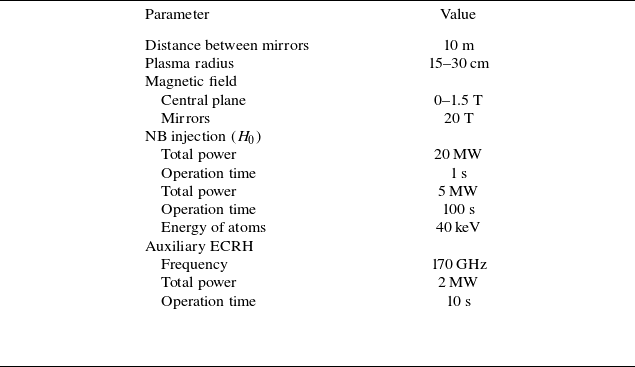
The main parameters of the first stage of the GDMT facility are presented in table 1.
Basic parameters of the first stage of the GDMT facility.

During the second development phase, multi-mirror (Budker, Mirnov & Ryutov Reference Budker, Mirnov and Ryutov1971; Postupaev et al. Reference Postupaev2017) or helical (Beklemishev Reference Beklemishev2013; Sudnikov et al. Reference Sudnikov, Ivanov, Inzhevatkina, Kozhevnikov, Postupaev, Tolkachev and Ustyuzhanin2024) sections will be added to mitigate longitudinal particle and energy losses. The facility under design will establish a physical basis for thermonuclear applications, including a neutron source and a prospective thermonuclear reactor based on an open-ended magnetic trap with a linear axisymmetric configuration.
Calculations presented by Moyzykh et al. (Reference Moyzykh2026) demonstrate that implementing the diamagnetic confinement regime with $\beta \to 1$
(Beklemishev Reference Beklemishev2016) in the central section, combined with effective suppression of axial losses by multi-mirror or helical sections, enables the development of deuterium–tritium (D–T) and even deuterium–deuterium (D–D) fusion reactors based on the GDMT concept operating under ignition conditions.
$\beta \to 1$
(Beklemishev Reference Beklemishev2016) in the central section, combined with effective suppression of axial losses by multi-mirror or helical sections, enables the development of deuterium–tritium (D–T) and even deuterium–deuterium (D–D) fusion reactors based on the GDMT concept operating under ignition conditions.
3. GDT facility
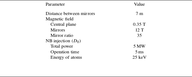
Figure 2 shows the GDT facility with its key components and primary diagnostic systems, which are described in detail by Soldatkina et al. (Reference Soldatkina2025). Table 2 lists the main engineering parameters of the GDT device.
Main parameters of the GDT facility.

Scheme of the GDT facility with its key elements and basic diagnostics.

Previous experiments at the GDT facility have yielded the following key results in the physics of open-ended magnetic traps.
-
(i) A method for suppressing losses caused by MHD instabilities has been developed and a plasma beta of $\beta \geqslant 0.5$
has been achieved in an axisymmetric magnetic field configuration (Simonen et al. Reference Simonen, Anikeev, Bagryansky, Beklemishev, Ivanov, Lizunov, Maximov, Prikhodko and Tsidulko2010).
$\beta \geqslant 0.5$
has been achieved in an axisymmetric magnetic field configuration (Simonen et al. Reference Simonen, Anikeev, Bagryansky, Beklemishev, Ivanov, Lizunov, Maximov, Prikhodko and Tsidulko2010). -
(ii) Processes governing axial thermal transport have been investigated in detail. A technique to overcome classical Spitzer thermal conductivity has been developed and electron heating up to 1 keV has been demonstrated (Bagryansky et al. Reference Bagryansky, Shalashov, Gospodchikov, Lizunov, Maximov, Prikhodko, Soldatkina, Solomakhin and Yakovlev2015; Soldatkina et al. Reference Soldatkina, Maximov, Prikhodko, Savkin, Skovorodin, Yakovlev and Bagryansky2020).
-
(iii) Approaches to mitigate the effects of kinetic instabilities have been identified Zaytsev et al. (Reference Zaytsev2014).

The current GDT experimental programme focuses on the following key tasks, essential for validating the GDMT project:
-
(i) development of MHD stabilisation techniques for high-beta plasma (
$\beta \to 1$
), including the use of a conductive wall and active feedback systems; -
(ii) electron cyclotron resonance heating (ECRH) and generation of the initial plasma;
-
(iii) investigation of radial transport processes;
-
(iv) warm plasma fuelling.

4. Upgrades to key GDT diagnostic systems
During the 2024–2025 upgrade campaign, several critical engineering systems and core diagnostic suites of the GDT facility were modernised.
-
(i) The vacuum system was converted to oil-free pumping technology.
-
(ii) The reliability of the magnetic mirror coils was enhanced.
-
(iii) A new second-harmonic X-mode electron cyclotron resonance heating system was developed.
-
(iv) Neutral beam power supply systems were redesigned for improved performance.
-
(v) The Thomson scattering diagnostic was upgraded to enhance spatial and temporal resolution.
-
(vi) A bolometer array was installed to measure charge-exchange losses in the central cell.
-
(vii) Diagnostics for fusion reaction products were expanded and modernised.
-
(viii) A Mirnov coil array was implemented for MHD instability monitoring.
4.1. Upgrade of Thomson scattering diagnostics
As a result of the upgrade, the Thomson scattering diagnostic system now enables time-resolved measurements of radial profiles of electron temperature and density. Its key components include:
-
(i) a Nd:YAG laser (wavelength 1064 nm) delivering a single pulse with 1.5 J energy;
-
(ii) a Beamtech SGR-30 PBLS laser operating at the same wavelength, providing 10 pulses per plasma shot with 3 J energy per pulse;
-
(iii) digital spectrometers based on bandpass interference filters for processing the scattered light signals (Lizunov et al. Reference Lizunov, Berbassova, Khilchenko, Maximov, Puryga and Zubarev2019).
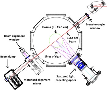
A dedicated calibration procedure employing Raman scattering in molecular gases is performed to ensure accurate determination of the absolute electron density. The diagnostic system enables measurements of electron temperature in the range of 20 eV to 3 keV with an accuracy of 3 %. The arrangement of diagnostic components near the GDT vacuum vessel is shown schematically in figure 3.
Arrangement of Thomson scattering diagnostic elements near the vacuum vessel of GDT device.

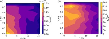
Figure 4 presents an example of the time evolution of radial electron density and temperature profiles in standard GDT operation mode measured with the upgraded Thomson scattering diagnostic.
Examples of temporal profiles of (a) radial electron density and (b) temperature profiles measured with the upgraded Thomson scattering diagnostic system in one of the discharges.

4.2. Upgrade of fusion product diagnostics at GDT
Experiments at the GDT facility are primarily carried out with deuterium plasma. The deuterium–deuterium (D–D) fusion reaction proceeds via two branches of approximately equal probability:
 \begin{align} {D} + {D} \xrightarrow {50\%} {}^3{\textit{He}}\ (0.82\ \mathrm{MeV}) + n\ (2.45\, \mathrm{MeV}),\\[-10pt]\nonumber \end{align}
 \begin{align} {D} + {D} \xrightarrow {50\%} {T}\ (1.01\ \mathrm{MeV}) + p\ (3.02\, \mathrm{MeV}). \end{align}
The fusion product diagnostics at GDT focus exclusively on detecting neutrons and protons. The spatial distribution of proton emission regions is measured using ultra-thin dead-layer silicon semiconductor detectors installed near the first wall inside the vacuum vessel. The GDT magnetic field is relatively weak; consequently, the gyroradii of 3.02 MeV protons from D–D fusion exceed the vessel radius. This allows localisation of the proton emission region with a spatial resolution of 20 $\times$
20 cm
$\times$
20 cm $^2$
using dedicated collimators (Pinzhenin & Maximov Reference Pinzhenin and Maximov2024).
$^2$
using dedicated collimators (Pinzhenin & Maximov Reference Pinzhenin and Maximov2024).
Axial proton yield profile measured before (6050 $\unicode{x03BC} s$
) and after (6650
$\unicode{x03BC} s$
) and after (6650 $\unicode{x03BC} s$
) the onset of the Alfvén ion cyclotron (AIC) instability.
$\unicode{x03BC} s$
) the onset of the Alfvén ion cyclotron (AIC) instability.

Figure 5 shows an example of axial proton yield profiles measured before and after the onset of the Alfvén ion cyclotron (AIC) instability. The coordinate $z \approx 170\,\rm cm$
corresponds to the turning point of hot ions with a pitch angle of
$z \approx 170\,\rm cm$
corresponds to the turning point of hot ions with a pitch angle of $45^\circ$
, matching the injection angle of the neutral beams. For comparison, results from the DOL kinetic code (Yurov, Prikhodko & Tsidulko Reference Yurov, Prikhodko and Tsidulko2016) are presented for three values of the angular spread of the hot ion distribution function. An angular spread of
$45^\circ$
, matching the injection angle of the neutral beams. For comparison, results from the DOL kinetic code (Yurov, Prikhodko & Tsidulko Reference Yurov, Prikhodko and Tsidulko2016) are presented for three values of the angular spread of the hot ion distribution function. An angular spread of $3^\circ$
approximately corresponds to the intrinsic divergence of the neutral beams. The data in figure 5 demonstrate that AIC instability development leads to a moderate increase in the angular spread of hot ions, but does not cause significant scattering into the loss cone, confirming earlier conclusions reported by Zaytsev et al. (Reference Zaytsev2014).
$3^\circ$
approximately corresponds to the intrinsic divergence of the neutral beams. The data in figure 5 demonstrate that AIC instability development leads to a moderate increase in the angular spread of hot ions, but does not cause significant scattering into the loss cone, confirming earlier conclusions reported by Zaytsev et al. (Reference Zaytsev2014).
Neutron flux measurements are performed using organic scintillation detectors. This diagnostic system has been retained without major modifications during the recent upgrade campaign.
4.3. Upgrade of energy balance diagnostics
A key parameter of a prospective fusion reactor based on an open magnetic trap is its energy efficiency; therefore, studying possible energy loss channels from the system is critically important for validating the design of such a reactor. To establish the energy balance within the trap, it is necessary to measure the amounts of energy supplied to the plasma and lost from it through various channels. The considered potential energy loss channels include: longitudinal losses to the plasma collector located beyond the trap’s mirror, losses to radial limiters that confine the plasma size and have direct contact with it, as well as losses due to charge exchange of plasma ions with residual gas. Research on energy loss channels is currently underway at the GDT, where a corresponding suite of diagnostics is being developed by Soldatkina et al. (Reference Soldatkina, Meyster, Yakovlev and Bagryansky2024).
In 2025, the system of pyroelectric bolometers measuring energy losses to the wall of the GDT central chamber was expanded with additional sensors. Eleven new detectors, equipped with shutters to protect against titanium deposition, were installed on the wall of the ‘western’ half of the vacuum chamber. Additionally, one more detector was installed in the ‘eastern’ half near the output ports of the neutral beam injectors, as an elevated level of charge-exchange losses is expected in this region due to plasma interaction with an active target – specifically, the atoms of the injected beams.
All sensors are equipped with a galvanically isolated battery-powered supply system, activated by a light pulse from the facility’s control system. Additionally, the data acquisition system for all sensors has been upgraded to extend the measurable signal range up to 66 W cm $^{-2}$
.
$^{-2}$
.
The upgraded pyrobolometer system, which previously allowed measurements in only one half of the central chamber, now covers the entire length of the GDT. Consequently, it becomes possible to measure energy losses from the plasma caused by charge exchange of ions with residual neutral gas, as well as losses due to electromagnetic radiation emitted from the plasma. The system enables the study of both temporal and spatial dependencies of power losses through these channels. Figure 6 shows a charge-exchange loss distribution to the vacuum chamber wall that is characteristic of GDT under a standard magnetic configuration: the highest power fluxes should be observed near the turning points of fast ions ( $z=\pm 190$
cm from the facility centre). However, the turning points have a certain width along the facility axis, which is why noticeable signals are also observed on adjacent sensors. Furthermore, the magnitude of charge-exchange losses strongly depends on the gas puffing scenario. In the example presented, gas was puffed from the eastern side of the facility, thus causing a high power density of charge-exchange losses to be observed on the
$z=\pm 190$
cm from the facility centre). However, the turning points have a certain width along the facility axis, which is why noticeable signals are also observed on adjacent sensors. Furthermore, the magnitude of charge-exchange losses strongly depends on the gas puffing scenario. In the example presented, gas was puffed from the eastern side of the facility, thus causing a high power density of charge-exchange losses to be observed on the $z = 204$
cm bolometer, located near the eastern turning point. Additionally, the high level of power flux at
$z = 204$
cm bolometer, located near the eastern turning point. Additionally, the high level of power flux at $z = 35$
cm is associated with the sensor’s location near the output port of the injected neutral beams and is presumably determined by a high level of charge exchange of fast ions in this region.
$z = 35$
cm is associated with the sensor’s location near the output port of the injected neutral beams and is presumably determined by a high level of charge exchange of fast ions in this region.
Example temporal dependencies of power losses to the vacuum chamber wall measured by the array of pyroelectric bolometers. Red colouring corresponds to the probes in the eastern half of the trap and blue to the western half.

Signals from individual sensors are used to calculate the total power losses to the vacuum chamber wall. For this purpose, the signal from each bolometer is multiplied by an area corresponding to the lateral surface of a cylinder with a radius of 45 cm (the distance from the facility axis to the sensors) and a height equal to the distance between the midpoints of the intervals to two adjacent sensors. Summing these values yields the instantaneous power losses to the facility wall; an example of such power calculations for one of the discharges is shown in figure 7.
Example of total measured power losses to the central chamber walls of the GDT during a discharge measured by the array of pyroelectric bolometers.

5. MHD plasma stabilisation using a conductive wall
To mitigate transverse transport associated with MHD instabilities, the vortex confinement method (Beklemishev et al. Reference Beklemishev, Bagryansky, Chaschin and Soldatkina2010) is currently employed at GDT. This technique requires direct electrical contact between the plasma and absorber electrodes. However, if axial losses are reduced below a certain threshold, this electrical contact will be disrupted.
A potential solution involves a two-stage approach:
-
(i) transition to a high-beta regime using vortex confinement;
-
(ii) suppression of MHD-driven losses through the interaction of plasma diamagnetic currents with image currents induced in surrounding conductive structures.
MHD stabilisation by a conducting wall has been extensively investigated over recent decades (see, for example, Kaiser & Pearlstein Reference Kaiser and Pearlstein1985; Berk, Wong & Tsang Reference Berk, Wong and Tsang1987) and in more recent studies (Zeng & Kotelnikov Reference Zeng and Kotelnikov2024; Kotelnikov Reference Kotelnikov2025). Recent analysis by Kotelnikov (Reference Kotelnikov2025) predicts the effectiveness of this stabilisation method for $\beta \geqslant 0.8$
, provided that the conducting wall configuration surrounding the plasma is optimised.
$\beta \geqslant 0.8$
, provided that the conducting wall configuration surrounding the plasma is optimised.
One of the key parameters of a conductive stabiliser is its proximity to the plasma boundary. To determine the minimum permissible distance between the plasma boundary and the stabiliser surface, an experiment was conducted using a movable limiter. The methodology of this experiment is illustrated in figure 8.
Method for determining the minimum permissible radius of the inner surface of a conducting stabiliser.

The gyroradii of hot ions with energies of approximately 25 keV are comparable to the characteristic plasma radius. Consequently, the orbits of a significant fraction of hot ions extend beyond the plasma boundary.
In this experiment, the dependencies of the diamagnetic signal and fusion reaction rate on the radial position of the movable limiter were measured. These dependencies are presented in figure 9. The diamagnetic signal is proportional to the total energy content of the hot ion population, while the fusion reaction rate depends strongly on both the total number and the energy spectrum of hot ions.
(a) Diamagnetic signals from loops positioned 14 and 74 cm from the central plane as a function of limiter radial position; (b) fusion reaction rate versus limiter position.

The data in figure 9 indicate that the inner radius of the conducting stabiliser may be set to 22 cm relative to the r = 0 axis. Based on these results and the analysis of Kotelnikov (Reference Kotelnikov2025), a preliminary design of the conducting stabiliser was developed. Its 3-D model is shown in figure 10.
3-D model of a conducting wall with an optimised configuration surrounding the plasma.

As noted previously, successful demonstration of MHD stabilisation using a conducting wall at the GDT requires achieving $\beta \geqslant 0.8$
(Kotelnikov Reference Kotelnikov2025). The maximum
$\beta \geqslant 0.8$
(Kotelnikov Reference Kotelnikov2025). The maximum $\beta$
value attained with the current GDT configuration is
$\beta$
value attained with the current GDT configuration is $\beta \approx 0.6$
(Simonen et al. Reference Simonen, Anikeev, Bagryansky, Beklemishev, Ivanov, Lizunov, Maximov, Prikhodko and Tsidulko2010). To reach
$\beta \approx 0.6$
(Simonen et al. Reference Simonen, Anikeev, Bagryansky, Beklemishev, Ivanov, Lizunov, Maximov, Prikhodko and Tsidulko2010). To reach $\beta \geqslant 0.8$
, two measures are planned:
$\beta \geqslant 0.8$
, two measures are planned:
-
(i) extension of the neutral beam injection pulse duration from 5 ms to 10 ms to enhance plasma diamagnetism;
-
(ii) use of the recently upgraded electron cyclotron resonance heating system to increase the electron temperature
$\langle T_e \rangle$
, extend the confinement time of hot ions, and thereby boost both plasma diamagnetism and the volume-averaged beta
$\langle \beta \rangle$
.


6. New second-harmonic X-mode ECRH system at GDT
A new electron cyclotron resonance heating system for the GDT facility was developed during 2024–2025 (Khusainov et al. Reference Khusainov, Balakin, Gospodchikov, Solomakhin and Shalashov2024). The system operates at the second harmonic of the X-mode with a frequency of 54.5 GHz, delivering up to 0.8 MW of microwave power for pulse durations of up to 10 ms. Figure 11 shows the layout of the upgraded ECRH system installed at GDT.
Layout of the upgraded second-harmonic X-mode ECRH system at GDT.

Radial profiles of electron density and temperature in discharges without ECRH (blue) and with ECRH applied (red) measured by Thomson scattering system and averaged over a series of discharges.

Preliminary experiments, the results of which are presented in figure 12, employed microwave injection from the low-field side (LFS), as illustrated in figure 11. During these experiments, the microwave power reaching the plasma boundary was 700 kW.
Although the preliminary results demonstrate a measurable increase in electron temperature, quasi-optical simulations (Khusainov et al. Reference Khusainov, Balakin, Gospodchikov, Solomakhin and Shalashov2024) predict low absorption efficiency for LFS injection. Figure 13 compares the simulated power deposition for LFS and high-field side (HFS) injection scenarios. Only 45 % of the incident power is absorbed in LFS injection due to reflection from the resonance layer, whereas HFS injection eliminates this reflection and achieves 96 % absorption efficiency. Based on the experimental results and simulation predictions, HFS microwave injection is being implemented to achieve higher electron temperature.
Figure 14 shows the design of the HFS microwave launch system.
Quasi-optical simulation results for microwave injection from the (a) low-field side (LFS) and (b) high-field side (HFS) (Khusainov et al. Reference Khusainov, Balakin, Gospodchikov, Solomakhin and Shalashov2024).

Design of the high-field side microwave launch system.

Figure 14. Long description
A cross-sectional view of a cylindrical structure with internal components and color-coded parts. The outer shell is gray with red supports. Inside, a blue cylindrical rod runs horizontally. Green and red components are visible near the top, with the green part appearing to be a support or connector. The red parts are likely structural supports or connectors. The gray shell has several circular cutouts and structural reinforcements.
7. Plasma injection for bulk plasma particle balance using a Marshall gun
To address the challenge of maintaining particle balance in the bulk plasma, we investigated plasma injection using a Marshall gun (Rashleigh & Marshall Reference Rashleigh and Marshall1978). Figure 15 illustrates the operating principle of the device.
First, the gap between two coaxial electrodes is filled with hydrogen or deuterium gas. Application of a bias voltage creates an electric field (red arrows), triggering electrical breakdown in the gas. Then, the discharge current (yellow arrows) flows through the plasma and returns via the central electrode, generating an azimuthal magnetic field (white arrows). The interaction between the radial current component in the plasma and the azimuthal magnetic field produces a Lorentz force that accelerates the plasma along the gun axis (blue arrows).
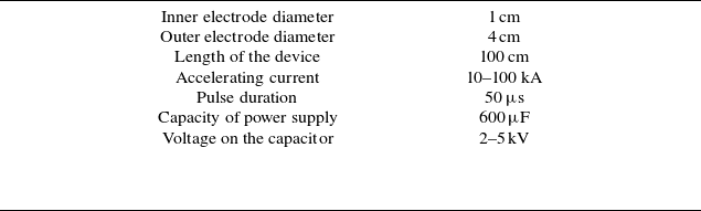
The parameters of the Marshall gun developed for GDT experiments are summarised in table 3.
The Marshall gun was installed in one of the GDT expander sections, replacing the standard arc plasma source (see figure 16). Results of preliminary injection experiments are presented in figure 17.
Parameters of the Marshall gun developed for GDT experiments.

Operating principle of the Marshall gun.

Installation of the Marshall gun in the expander section for plasma jet injection experiments.

Based on these preliminary results, the Marshall gun can be considered a viable particle injector concept for the GDMT facility. Further development is required to create an injector based on this principle with near-unity gas utilisation efficiency and a pulse repetition rate of ${\sim}1$
kHz, capable of delivering a cold particle flux equivalent to several kiloamperes of ion current into the axial region of the plasma column.
${\sim}1$
kHz, capable of delivering a cold particle flux equivalent to several kiloamperes of ion current into the axial region of the plasma column.
8. Conclusions
Experimental studies in support of the Gas-Dynamic Multiple-Mirror Trap (GDMT) concept are ongoing at the GDT facility. Key engineering systems and diagnostic suites have undergone substantial upgrades during the 2024–2025 campaign.
A preliminary design of an MHD stabilisation system based on a conducting wall has been developed, with an optimised inner radius of 22 cm determined experimentally.
A new second-harmonic X-mode ECRH system operating at 54.5 GHz has been commissioned. Preliminary experiments confirm the feasibility of this approach for electron heating, with quasi-optical simulations indicating that high-field-side injection will increase absorption efficiency from 45 % to 95 %.
The energy balance diagnostic system has been upgraded: an array of pyroelectric bolometers now spans the entire length of the GDT, enabling direct measurement of the total power flux from the plasma to the vacuum vessel wall.
Results of preliminary Marshall gun injection experiments: (a) temporal evolution of neutral beam power captured by the plasma; (b) temporal evolution of the diamagnetic signal.

Proof-of-principle experiments on bulk plasma fuelling using a Marshall gun injector have been successfully performed. The results support further development of this technique towards a high-repetition-rate ( ${\sim}1$
kHz) injector with near-unity gas utilisation efficiency for future GDMT-class devices.
${\sim}1$
kHz) injector with near-unity gas utilisation efficiency for future GDMT-class devices.
Acknowledgements
Editor Cary Forest thanks the referees for their advice in evaluating this article.
Funding
The study was supported by the Ministry of Science and Higher Education of the Russian Federation.
Declaration of interests
The authors report no conflict of interest.



 μs
μs μs
μs




 Open access

