


Introduction
In the fifth generation (5G) mobile radio access network, coherent beamforming spatial division multiplexing has been developed and commercially introduced by massive multiple-input–multiple-output (mMIMO) technology [Reference Marzetta1]. It has been shown that distributed mMIMO (D-MIMO) exhibits much higher cell capacity and significant spatial division selectivity in highly dense user equipment (UE) circumstances compared to collocated mMIMO (C-MIMO) [Reference Tawa, Kuwabara, Maruta and Kaneko2–Reference Tawa, Kuwabara, Maruta, Ando and Kaneko4], due to its larger spatial degree of freedom. Mobile phone operators prioritize energy efficiency as well as network capacity. mMIMO is an energy-efficient technology, as it delivers energy and data to where they are necessary using beamforming, in contrast to the fixed beam remote radio head that spreads energy almost wastefully everywhere. The theory and simulation of mMIMO’s bit efficiency and the number of simultaneous connected UE (K), taking into account significant hardware consumption, such as power amplifier (PA) efficiencies at base stations (BSs) and UEs, fixed power consumption (control signals, backhaul, etc.), power consumed by local oscillator (LO) at BSs, power required to run circuit components at both BSs and UEs, and the computational efficiency at both BSs and UEs, power required for backhaul traffic, and power required for coding and decoding of data signals, have been calculated and resulted in the existence of global optimum values in the number of transceivers M and the number of users K [Reference Björnson, Sanguinetti, Hoydis and Debbah5]. The simulated energy efficiency of simple conjugate beamforming and additional enhancement using max–min power control methods in 2 GHz cell-free mMIMO has been reported in reference [Reference Yang and Marzetta6]. The simulated energy efficiency of D-MIMO at the downlink (DL) transmit power as the denominator at arbitral frequencies has been reported in reference [Reference He, Li, Zheng and You7]. There is no mention of over-the-air (OTA) measurements nor comparative discussion focusing differences between D-MIMO and C-MIMO antenna geometrical arrangements yet.
This paper presents an experimentally measured OTA bit efficiency using the 28 GHz testbeds, comparing C-MIMO and D-MIMO in terms of the ratio (K/M) of simultaneously number of connected UE (K) to number of transceivers (M), where each UE is null steered by beams to other UEs in a cell using the zero-forcing (ZF) method. The UE’s reception signal-to-noise ratio (SNR) is dominated by the leakage signal deposition beams to others in a cell. Then paper generalizes the study to a realistic scenario serving a sub-6 GHz small cell to characterize the effective isotropic sensitivity (EIS) and bit efficiency of C-MIMO and D-MIMO, to clarify the impacts of spatial division selectivity on the bit efficiencies.
An earlier version of this paper was presented at the 53rd European Microwave Conference and published in its proceedings [Reference Kaneko, Kuwabara, Tawa and Maruta8]. This paper extends the earlier version by additionally discussing the necessity and design of the transmitter (TX), receiver (RX), and LOs synchronization over the distributed antennas (DAs) for the coherent beamforming comparing three architectures including radio over fibre (RoF) techniques, and the studies of simulated energy efficiencies comparing the two derivative details of ZF algorithms of conventional zero-forcing (CZF) and normalized zero-forcing (NZF) over various numbers of transceivers (M).
The remainder of this article is organized as follows. The “28 GHz testbeds and system parameters” section presents the review of the coherent beamforming C-MIMO and D-MIMO architectures, the 28 GHz OTA measurements layouts, and the system parameters. The “28 GHz siulation and OTA measurement” section presents the 28 GHz simulation and OTA measurements of DL SNR and bit efficiencies. The “Small-cell scenarios simulation” section expands the discussion to sub-6 GHz small-cell scenario simulations in cases of various number of transceivers and various number of UE, and the beam-forming methods cover CZF and NZF in D-MIMO and C-MIMO. Finally, Section V summarizes and provides the conclusion.
28 GHz testbeds and system parameters
Architectures for coherent beamforming across access point DAs
The acceptable phase fluctuation across DAs is 500 psec p-p, corresponding to a 5-degree p–p phase fluctuation at 28 GHz under the complete phase lock systems, to achieve a SNR greater than 24 dB for coherent beamforming 256 quadrature amplitude modulation (QAM) transmission. The commercially deployed synchronization technologies are available for the geometrically separated BSs. The most well-known synchronization systems for geometrically apart equipment on earth using signals from multiple artificial satellites are the global positioning system (GPS) and the global navigation satellite system (GNSS). Their known and achievable accuracies are around less than +/−100 nsec, which is insufficient for joint coherent beamforming. Another issue with using GPS or GNSS for BS DA synchronization indoors is that DAs within a system cannot always catch signals from the same combination of satellites. Today, the most popular synchronization system for BSs is the Institute of Electrical and Electronics Engineers (IEEE) 1588 Precision Time Protocol based on Ethernet. It realizes microsecond-order accuracy. Basically, those doesn’t provide coherent phase lock across the DAs, are insufficient for joint coherent beamforming.
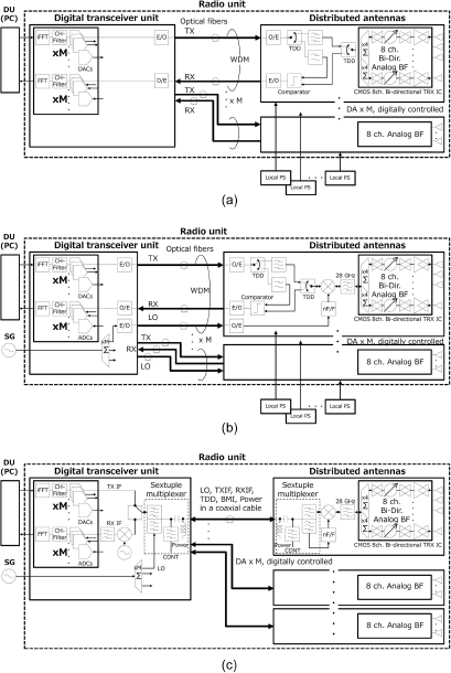
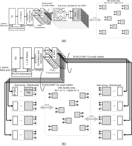
Figure 1 shows three kinds of the block diagram of the D-MIMO radio unit, which are capable of coherent beamforming across geometrically separated DAs. Figure 1(a) shows the fronthaul connection by the optical fibers with RoF technique. RoF is today one of most refined technique to establish a coherent connection between the geometrically separated units with low latency and extended connection length. The sub-6 GHz RoF based D-MIMO are demonstrated in references [Reference Sezgin, Aabel, Jacobsson, Durisi, He and Fager9, Reference Aabel, Jacobsson, Coldrey, Olofsson, Durisi and Fager10]. In particular, reference [Reference Aabel, Jacobsson, Coldrey, Olofsson, Durisi and Fager10] provides a details description of the calibration procedures between the TX and RX paths including TX fibers and RX fibers, for the 1-bit RoF system at sub-6 GHz. And Fig. 1(b) shows the possible enhancement of RoF to a millimeter-wave system combination using up- and down-converters. Figure 1(c) shows another fronthaul connection architecture using the coaxial cables with the sextuple multiplexer, featuring a single cable for each DA. In this system, the sextuple multiplexer is superimposing the LO signal, time-division duplexed TX, RX intermediate frequency (IF) signals, time division duplex (TDD) timing signal, static analog beamforming weights for each DA, and direct current (DC) power supply [Reference Tawa, Kuwabara, Maruta and Kaneko2]. In either case, where coaxial cables or RoF are for millimeter-wave D-MIMO, a LO distribution and up- and down-converters are necessary. The additional LO synchronization feature between DAs is not necessary as far as the LO signal is distributed from a LO generator. We developed and used a sextuple multiplexer that utilizes coaxial cable connection, due to the following considerations
28 GHz radio unit block diagram: (a) DAs and connected by the optical fibers with RoF technique; (b) DAs are connected by the optical fibers with RoF and the up- and down-converters, and (c) DAs are connected by the coaxial cables with the sextuple multiplexer and up- and down-converters.
.
– In the coaxial cable system, TX and RX cable paths can be treated part of the propagation channels under the reciprocity based ZF, after once the calibration has been completed. This is because, in a DA, a physically same path is used for both the uplink (UL) and DL. However, reciprocity over fibers is not guaranteed always due to the use of different wave lengths, as well as photo devices in the UL and DL.
– The calibrations are required to align the individual variation of each TX/RX ratio for the reciprocity based ZF, which are carried out in the same manner for both RoF and coaxial cable systems [Reference Tawa, Kuwabara, Maruta and Kaneko3].
– The noise figure (NF) of commercially available RoF modules is typically large [11], with values of several tens in decibel. This requires us to share the UL dynamic range with NF.
– Local power supplies are necessary at each DAs in RoF. However, the coaxial cable and multiplexer provide DC power, which is convenient for both the laboratory experiments at commercial deployment.
– Possible extension length by coaxial cable is several tens of meters, which is shorter than using RoF. However, the length is sufficient for D-MIMO OTA experiments and demonstrating the benefits of D-MIMO in the spatial division selectivity [Reference Tawa, Kuwabara, Maruta, Ando and Kaneko4].
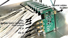
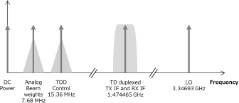
The LO frequency is 3.34693 GHz, and the TX and RX IF are 1.47456 GHz for minimizing the insertion loss of cables and realizing the separation between signals by the realistic band pass filters. The LO is multiplied by eight, and the TX and RX IF are linearly converted to and from 28 GHz at each DA. Figure 2 shows the photo of prototyped sextuple multiplexer and Fig. 3 shows the signals allocation on the frequency axis.
Photograph of the sextuple multiplexer.
Signals allocation on a frequency axis.
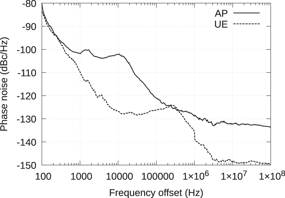
The fundamental LO signals at 3.34693 GHz are generated by Anritsu MG3700A and Rohde & Schwarz SMW200A for access point (AP) and UEs, respectively. Figure 4 shows the measured phase noise characteristics of AP LO and UE LO. The calculated RMS jitters, integrating phase noise from the DMRS interval to the bandwidth and multiplied to 28 GHz band, are 0.13 psec p–p and 0.03 psec p–p at AP and UEs, respectively. These are sufficient to achieve the phase accuracy requirement for 256QAM transmission as stated at the beginning of this section.
LO phase noise of AP and UE at 3.34693 GHz.
28 GHz C-MIMO and D-MIMO testbeds OTA layouts
Figure 5(a) and (b) show the functional block diagram of the testbeds and the OTA experiment layouts for C-MIMO and D-MIMO, respectively. The RF testbeds consist of an AP radio unit (RU) and UE RU. An AP RU has an eight-channel digital transceiver and eight DAs, which have up and down linear converters, a 28 GHz complementary metal oxide semiconductor (CMOS) eight-channel transceiver IC [Reference Pang, Li, Kubozoe, Luo, Wu, Wang, You, Fadila, Saengchan, Nakamura, Alvin, Matsumoto, Liu, Narayanan, Qiu, Liu, Sun, Huang, Tokgoz, Motoi, Oshima, Hori, Kunihiro, Kaneko, Shirane and Okada12], and eight antenna elements arranged at half-wavelength intervals. The CMOS IC integrates the transmit and receive amplifiers, phase shifters, and TDD switches. The UE RU has the same design and configuration as the AP RU. Total number of antenna element at AP is 64 consists of eight DAs.
Functional block diagram and OTA layouts: (a) C-MIMO and (b) D-MIMO.
For C-MIMO measurements, the eight DAs are bundled into a phased array antenna system. The horizontal antenna element interval is 30 mm as the mechanical dimension of DA unit, which is around six wavelengths and sufficient to constrain the spatial degrees of freedom for C-MIMO in comparison to D-MIMO. Figure 6(a) shows a photograph of the C-MIMO AP with bundled DAs.
Photographs: (a) C-MIMO AP phased array by bundling eight DAs and (b) D-MIMO AP and UE arrangement whole layout.
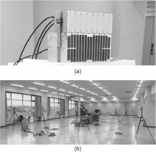
For D-MIMO measurements, all eight DAs surround the UE area. Four DAs are arranged at 3-meter intervals, and the other four DAs are located on the opposite side of the UE area, also at 3-meter intervals. The remaining four DAs are 17 meters apart. Figure 6(b) shows a photograph of the D-MIMO AP and UE layout.
System parameters
Table 1 shows the system parameters of the 28 GHz C-MIMO and D-MIMO testbeds, which are used in the simulation and measurements, except the small-cell simulation described in the next section. We note that the power consumption, including the radio units, digital transceivers, and the total maximum conductive power, of C-MIMO and D-MIMO are equal. The DA has the rated average equivalent isotropic radiated power (EIRP) of 22 dBm and has the −3 dB beam width of +/−30° in azimuth and +/−7° in elevation. The number of transceivers (M) is eight in CMIMO and D-MIMO. The C-MIMO AP consists of eight DAs rated average EIRP is 40 dBm.
System parameters of 28 GHz C-MIMO and D-MIMO testbeds
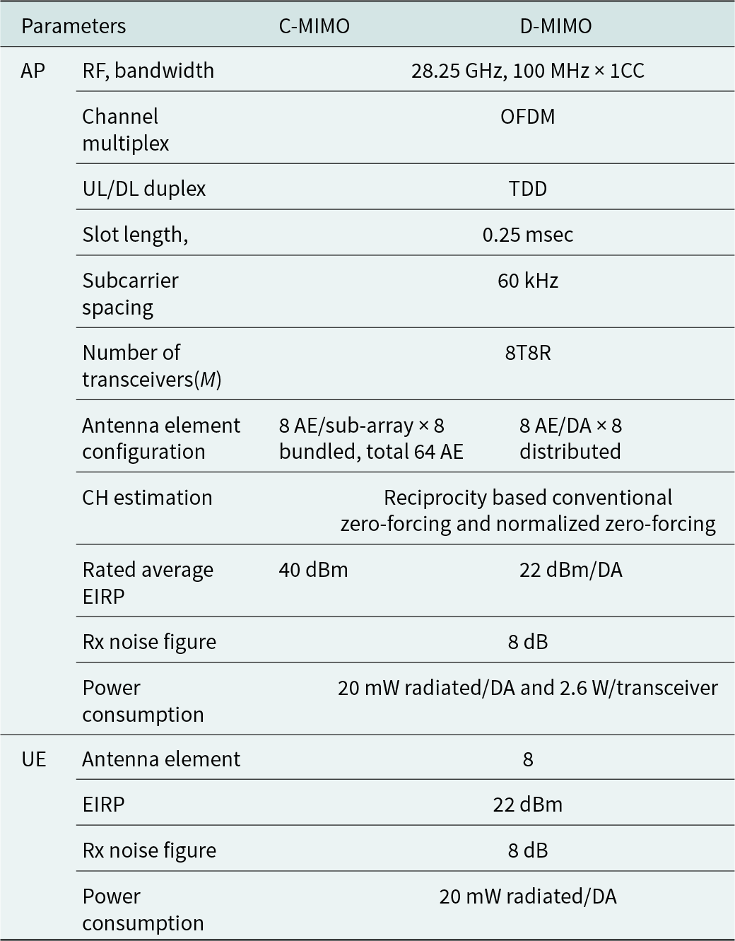
The number of UE of two, four, six, and eight are simulated and are measured. The UE are randomly and evenly located over the 8 m × 7 m area where line of sight (LoS) circumstances in both C-MIMO and D-MIMO measurements.
28 GHz simulation and OTA measurement
The channel estimation and creation of DL weights are based on the reciprocity-based ZF, i.e., each UE is null-steered from the summation of interference beams to other UEs in a cell. In this paper, we consider two derivatives of ZF. One is the CZF, where the DL weight is represented in Eq. (1), and the other is NZF, represented in (2), where the m-th row and k-th column element is divided by average amplitude  $a\left( k \right)$ for normalizing the summed conductive power over the layers. H is the propagation channel matrix observed from UL and has M (number of transceivers) rows and K (number of simultaneously connected layers) columns. There is no degradation, such as residual calibration error, phase noise, jitter, and nonlinearity, considered in the simulation. Furthermore, there is no motion of UE considered in the simulation and measurements.
 \begin{equation}{\mathbf{W}}_{{\text{CZF}}}^T = {{\mathbf{H}}^ + } = {\left( {{{\mathbf{H}}^H}{\mathbf{H}}} \right)^{ - 1}}{{\mathbf{H}}^H}\end{equation}
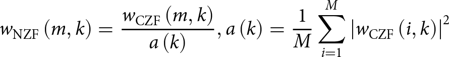 \begin{equation}{w_{{\text{NZF}}}}\left( {m,k} \right) = \frac{{{w_{{\text{CZF}}}}\left( {m,k} \right)}}{{a\left( k \right)}},{ }a\left( k \right) = \frac{1}{M}\mathop \sum \limits_{i = 1}^M {\left| {{w_{{\text{CZF}}}}\left( {i,k} \right)} \right|^2}\end{equation}
 Figure 7(a) shows the simulated complementary cumulative distribution function (CCDF) of the DL SNR at a UE using NZF, and Fig. 7(b) shows the corresponding OTA measurement. There are 2, 4, 6, and 8 UEs, occupying rectangular area variations of 0.3 × 0.2 m, 0.5 × 0.5 m, 1 × 1 m, 2 × 2 m, 4 × 3 m, 6 × 5 m, and 8 × 7 m, with UEs are randomly located in these various areas. We note that the electric field is not unique over the layers, which serve UEs individually, and the whole field is calculated and regenerated every time UE arrangements change. The DL reception and interference noise power for each individual UE at specific coordinates are summed over the null-steered beams to others and averaged over the other UEs’ ( $K - 1$) randomly distributed locations. Although the reception power of each UE generally decreases as the total number of UEs increases, assuming the total conductive power remains constant, D-MIMO exhibits smaller SNR dispersion across the number of UEs and their locations.
28 GHz DL SNR CCDF at UE: (a) simulated and (b) OTA measured.
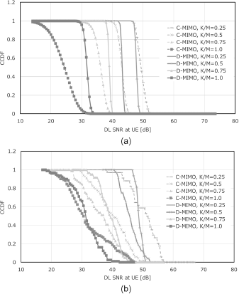
When K/M approaches 0.75, the throughput of both C-MIMO and D-MIMO systems reaches saturation [Reference Tawa, Kuwabara, Maruta, Ando and Kaneko4]. D-MIMO exhibits a 4 dB higher SNR than C-MIMO at a CCDF of 80%, with K/M = 0.75 in simulation. Moreover, D-MIMO exhibits a 7 dB higher SNR than C-MIMO at a CCDF of 80%, with K/M = 0.75 in OTA measurement. This result indicates that D-MIMO has a relatively higher energy efficiency than C-MIMO for serving the communication traffic to UE, especially in cases with a larger number of simultaneously connected UEs. The OTA measured D-MIMO SNR dispersion over the number of UEs and over the geometrical arrangement is smaller than that of C-MIMO. These tendencies and values are in good agreement with the simulated prediction in Fig. 7(a).
The determination of the bit efficiency is as follow.
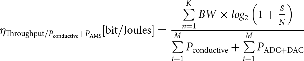 \begin{align}{\eta _{{\text{Throughput}}/{P_{{\text{conductive}}}} + {P_{{\text{AMS}}}}}}[ {{\text{bit}}/{\text{Joules}}} ] = \frac{{\sum\limits_{n = 1}^KBW \times lo{g_2}\left( {1 + \frac{S}{N}} \right)}}{{\sum \limits_{i = 1}^M{P_{{\text{conductive}}}} + \sum\limits_{i = 1}^M{P_{{\text{ADC}} + {\text{DAC}}}}}}{ }\nonumber\\ \end{align}
Here, we used the Shannon limit to calculate the throughput from the measured SNR, assuming an SNR upper limit of 40 dB, which is a reasonable assumption for realistic hardware implementation. The total RF conductive power and the consumption of digital-to-analog convertor (DAC) and analog-to-digital convertor (ADC) are considered as the denominator, since the spatial division selectivity is directly dependent on the number of transceivers M i.e., the degree of spatial freedom. We have omitted the hardware consumption depending on the practical implementation, such as low physical layer, LO oscillator, up- and down-converters, amplifiers and controlling circuits, to distinguish D-MIMO benefits from C-MIMO focusing their geometrical channels differences. The power of channel estimation computing is excluded as it is performed on a PC that is independent from the experimental testbeds.
Bit efficiencies of 99 Mbit/Joules and 192 Mbit/Joules are obtained for C-MIMO and D-MIMO, respectively, at K/M = 0.75 and a CCDF of 80%, according to Eq. (3).
Small-cell scenarios simulation
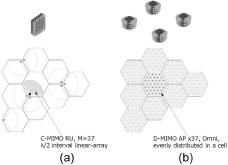
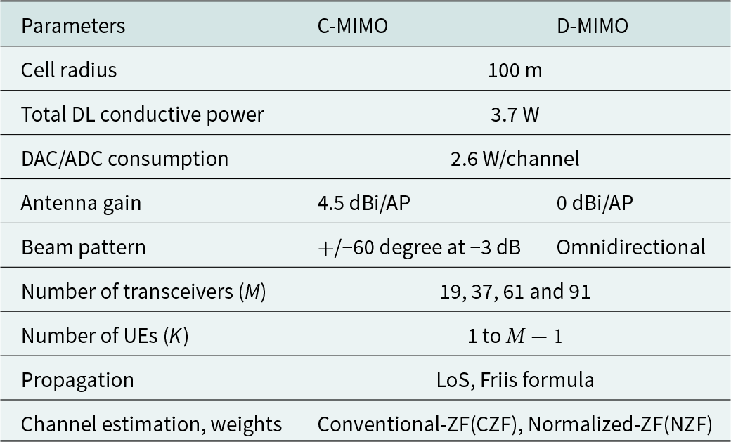
We expand the study to the simulation of a 3.75 GHz small-cell scenario, which is of the largest interest to the public today. We consider the cellular C-MIMO and D-MIMO serving a hexagonal small-cell with a radius of 100 meters under LoS circumstances, assuming an extremely high traffic demand area where mMIMO technology is required. The total rated radiated conductive powers are equal in both systems at 3.7 Watts. We assume a C-MIMO antenna gain of 4.5 dBi and a D-MIMO antenna gain per DA of 0 dBi. The numbers of transceivers (M) are 19, 37, 61, or 91, and the numbers of UEs (K) range from 1 to  $M - 1$. Figure 8 shows the (a) C-MIMO and (b) D-MIMO AP arrangements in the case where the number of transceivers is 37 for the examples. Table 2 presents the cell parameters used in the small-cell simulation. We note that these parameters can be easily transferred to 28 GHz and other radio frequencies by changing the geometrical size, as far as LoS circumstances are assumed. We have considered the DL transmitted conductive power as the denominators. Those are equal for D-MIMO and C-MIMO. We have omitted the hardware consumption depending on the practical implementation and power of channel estimation computing to focusing the geometrical propagation channel differences between D-MIMO and C-MIMO.
Arrangement of AP in case of M = 37: (a) C-MIMO and (b) D-MIMO.
Small-cell simulation parameters
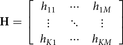
In this calculation, propagation matrix H under the Friis free space propagation follows.
 \begin{equation}{\mathbf{H}} = \left[ {\begin{array}{*{20}{c}}
{{h_{11}}}& \cdots &{{h_{1M}}} \\
\vdots & \ddots & \vdots \\
{{h_{K1}}}& \cdots &{{h_{KM}}}
\end{array}} \right]{\text{ }}\end{equation}
\begin{equation}{\mathbf{H}} = \left[ {\begin{array}{*{20}{c}}
{{h_{11}}}& \cdots &{{h_{1M}}} \\
\vdots & \ddots & \vdots \\
{{h_{K1}}}& \cdots &{{h_{KM}}}
\end{array}} \right]{\text{ }}\end{equation}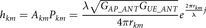 \begin{equation}{h_{km}} = {A_{km}}{P_{km}} = \frac{{\lambda \sqrt {{G_{AP\_AN{T_{}}}}{G_{UE\_AN{T_{}}}}} }}{{4\pi {r_{km}}}}{e^{\frac{{2\pi {r_{km}}}}{\lambda }j}}\end{equation}
 \begin{equation}{A_{km}} = \frac{{\lambda \sqrt {{G_{AP\_ANT}}{G_{UE\_ANT}}_{}} }}{{4\pi {r_{km}}}}\end{equation}
 \begin{equation}{P_{ij}} = {e^{\frac{{2\pi {r_{km}}}}{\lambda }j}}\end{equation}
Where, Akm represent the propagation losses between each AP antenna element and each UE, Pkm represent the phase differences between each AP antenna element and each UE, GAP_ANT is the antenna gain of AP (which is constant across all DAs), GUE_ANT is the antenna gain of UE (which is constant across all UEs), λ is wavelength at used frequency, and rkm represent the distances between each AP antenna element and each UEs.
The reception at each UE,  ${R_k}{\text{ }}\left( {k = 1{\text{ to }}K} \right)$ is calculated as:
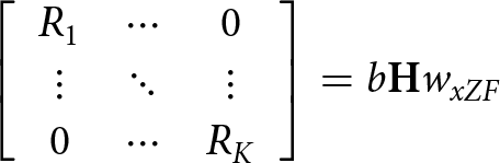 \begin{equation}\left[ {\begin{array}{*{20}{c}}
{{R_1}}& \cdots &0 \\
\vdots & \ddots & \vdots \\
0& \cdots &{{R_K}}
\end{array}} \right] = b{\mathbf{H}}{w_{xZF}}{\text{ }}\end{equation}
\begin{equation}\left[ {\begin{array}{*{20}{c}}
{{R_1}}& \cdots &0 \\
\vdots & \ddots & \vdots \\
0& \cdots &{{R_K}}
\end{array}} \right] = b{\mathbf{H}}{w_{xZF}}{\text{ }}\end{equation} Where,  ${w_{xZF}}$ is the DL weights calculated using (1) for CZF and additionally multiplied by (2) for NZF, and b is chosen for the total conductive power is equal to the system rated power avoiding saturation. The DL UE reception EIS heat-map can be obtained by repeating (4) to (8), where the UE locations are randomly changed across a cell.
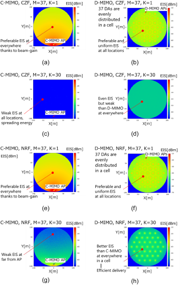
Figure 9 shows the simulated DL UE reception EIS heat-map using two derivatives of ZF in the case example of M = 37: (a) C-MIMO, CZF, M = 37, K = 1; (b) D-MIMO, CZF, M = 37, K = 1; (c) C-MIMO, CZF, M = 37, K = 30; (d) D-MIMO, CZF, M = 37, K = 30; (e) C-MIMO, NZF, M = 37, K = 1; (f) D-MIMO, NZF, M = 37, K = 1; (g) C-MIMO, NZF, M = 37, K = 30; and (h) D-MIMO, NZF, M = 37, K = 30, respectively. Then, Fig. 10 shows the simulated DL SNR CCDF at UE as the parameter of K/M from 0.03 to 0.97 in the case example of M = 37: (a) C-MIMO, CZF; (b) D-MIMO, CZF; (c) C-MIMO, NZF; and (d) D-MIMO, NZF.
Simulated DL UE reception EIS heat-map in case of (a) C-MIMO, CZF, M = 37, K = 1; (b) D-MIMO, CZF, M = 37, K = 1; (c) C-MIMO, CZF, M = 37, K = 30; (d) D-MIMO, CZF, M = 37, K = 30; (e) C-MIMO, NZF, M = 37, K = 1; (f) D-MIMO, NZF, M = 37, K = 1; (g) C-MIMO, NZF, M = 37, K = 30 and (h) D-MIMO, NZF, M = 37, K = 30.
Simulated DL SNR CCDF at UE in case example of M = 37 as the parameter of K/M: (a) C-MIMO, CZF; (b) D-MIMO, CZF; (c) C-MIMO, NZF and (d) D-MIMO, NZF.
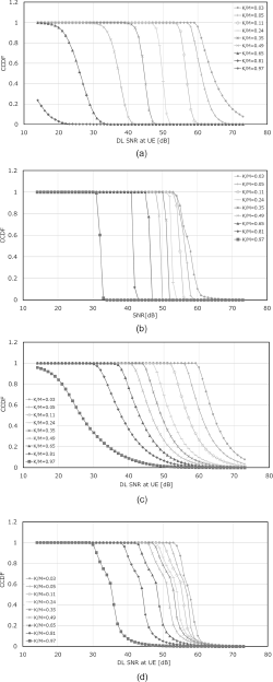
D-MIMO with NZF exhibits a 7 dB higher SNR at a CCDF of 80% and K/M = 0.81 than that of C-MIMO. In contrast, C-MIMO with NZF exhibits a 6 dB higher SNR at a CCDF of 80% and K/M = 0.03 than that of D-MIMO. It can be understood that the total radiated power of a particular layer in C-MIMO is larger than that in D-MIMO because the antenna element excitations are almost equal since they are collocated. However, D-MIMO’s antenna element excitations are nonuniform due to the ZF algorithm. C-MIMO can serve higher radiated power than D-MIMO for UEs in the case of a small K/M, which can be seen in the comparison of Fig. 9(a) and (b).
Due to CZF metrics (1), the DL weight amplitudes of each layer are inversely proportional to UL reception amplitudes at the BS. DL reception levels remain constant across UEs, and heat maps exhibit flatness within a cell, as observed in Fig. 9(c) and (d) when the number of connected UEs is large. The average DL reception EIS using NZF is greater than that using CZF, which indicates that NZF simultaneously achieves preferable cell capacity and coverage. These results are observed in the comparison between Fig. 9(c) and (g) at small K/M values and between Fig. 9(d) and (h) at large K/M values.
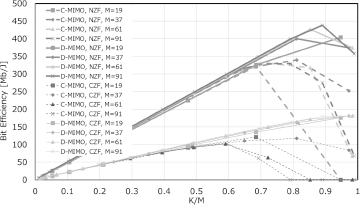
Figure 11 shows the summary of calculated bit efficiencies versus K/M. C-MIMO exhibits the maximum bit efficiency of 340 Mbit/Joules at K/M = 0.8, and D-MIMO exhibits a maximum of 440 Mbit/Joules at K/M = 0.9 using NZF. NZF exhibits approximately double the bit efficiency of CZF in both C-MIMO and D-MIMO across entire the K/M range. D-MIMO exhibits approximately 30% higher bit efficiency than C-MIMO in both CZF and NZF methods because D-MIMO’s saturated throughput is higher than that of C-MIMO [Reference Tawa, Kuwabara, Maruta, Ando and Kaneko4]. These are the most vivid benefits of D-MIMO compared to C-MIMO, as it can be understood that the average distances between APs and UEs in D-MIMO systems are smaller than those in C-MIMO systems.
Simulated bit efficiencies versus K/M at DL SNR CCDF of 80% as the parameters of architectures (C-MIMO, D-MIMO), beamforming methods (CZF, NZF) and number of transceivers M.
Conclusion
OTA measured and simulated bit efficiency in C-MIMO and D-MIMO using eight transceivers 28 GHz testbeds are presented. The measurement tendencies agreed well with the simulations. Next, we expanded our consideration to 3.75 GHz small-cell simulations.
- The 28 GHz OTA measured D-MIMO exhibits a 7 dB higher SNR than C-MIMO at a CCDF of 80% and a K/M ratio of 0.75, using NZF beamforming.
- The 28 GHz OTA measured D-MIMO bit efficiency (Throughput/(Pconductive + PAMS) reaches 192 Mbit/Joules using NZF beamforming.
- The generalized small-cell simulation predicts that the D-MIMO’s maximum bit efficiency is approximately 30% higher than C-MIMO in both CZF and NZF when K/M is greater than 0.75, due to the shorter average distances between UE and AP DAs in the D-MIMO system than C-MIMO.
- NZF beamforming exhibits almost double the bit efficiency of CZF in both C-MIMO and D-MIMO architectures.
- In experimental OTA measurements, the sextuple multiplexer that utilizes the coaxial cables connection between the centralized units to DAs provides the reciprocity based spatial division selectivity to distinguish D-MIMO from C-MIMO.
To the best of the author’s knowledge, reference [Reference Kaneko, Kuwabara, Tawa and Maruta8] is the first report on D-MIMO and C-MIMO bit efficiencies based on OTA measurements, and this paper is an extended version of it. Table 3 shows the benchmarking of bit efficiencies of BSs in comparison with previous works.
Benchmarking with previous works of mMIMO base station efficiencies
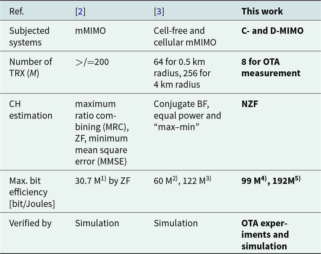
Note: 1) Global optimum, assuming all considerable HW consumption. 2), 3) Counting the total radiated conductive power for the consumption. 3GPP propagation loss considered. M = 64, 0.5 km cell radius and “max-min” power control: 2) cellular mMIMO; 3) cell-free mMIMO. Authors read the values from the figures. 4), 5) Calculated from measured SNR. Counting the total radiated conductive power and transceiver power consumption as the denominators. All UE are LoS from all AP and K/M = 0.75: 4) C-MIMO; 5) D-MIMO.
Acknowledgements
Authors thank Professor Kenichi Okada and his team at Tokyo Institute of Technology for the research and development of CMOS transceiver ICs.
Competing interests
The authors declare none.

Tomoya Kaneko received the B.S. degree in physics from Tokyo University of Science, Japan and the M.S. degree in science from University of Tsukuba, Japan, in 1984 and 1986 respectively. He joined NEC Corporation, Japan in 1986, where he has been engaged in design and development of Microwave and millimeter-wave circuits, their MCMs and sub-systems for radio communication systems. From 1999 to 2002, he was an engineer at NEC America Inc., USA, where he developed GaAs MMICs for millimeter-wave P–P radios. His current interests are millimeter-wave technologies and massive-MIMO considering their application to the mobile access networks. He had been serving as a TPC member and an overseas advisor of the IEEE BiCMOS and Compound Semiconductor Integrated Circuits and Technology Symposium (BCICTS) for 12 years.

Toshihide Kuwabara received the B.E. degree and the M.E. degree in electrical engineering from Waseda University, Japan, in 1991 and 1993 respectively. He joined NEC Corporation, Japan in 1993, and has been leading the development of millimeter-wave MMIC and sub-systems through design to production. His current focus is millimeter-wave and subTHz IC and system development toward beyond 5G and 6G. He is serving as a TPC member of the IEEE BiCMOS and Compound Semiconductor Integrated Circuits and Technology Symposium (BCICTS).

Noriaki Tawa received the B.Sc. degree from Hiroshima University, Japan, in 2003, and M.Sc. and Ph.D. degrees from Osaka University, Japan, in 2005, 2008, respectively. He had held research fellowships from Japan Society for the Promotion of Science from 2007 to 2008. In 2008 he entered NEC Corporation where he has been engaged in the high efficiency PAs and the bit-streamer technologies development for base-stations. He is currently focusing the digital beam-forming massive MIMO technology in quasi-/millimeter-wave frequency range and high efficiency PAs in sub-6 GHz range.

Yasushi Maruta received the B.E. degree in electrical engineering and the M.E. degree in electronics from Tohoku University in 1994 and 1996, respectively. He joined NEC Corporation in 1996, where he has been engaged in the development of baseband signal processing parts on base-stations for mobile wireless communication. He is currently focusing the massive-MIMO technology enhancement in millimeter-wave and sub-terahertz frequency range.


 Open access