


1. Introduction
We regularly encounter and interact with deformable objects in daily life, either in a professional or domestic capacity. Yet even for humans some delicate operations such as cutting, welding or gluing prove comparatively difficult for a manipulation task and require one’s full attention. In many cases, robotics and machine vision present opportunities to solve specific tasks that we would find either difficult or costly to carry out ourselves. These tasks become even more difficult for robots when interact with dynamic deformable objects directly/indirectly. Manipulator arms require accurate and robust tracking system to deal with the infinite-dimensional configuration space of the deformable objects.
Objects are classified based on their geometry into three classes: uniparametric, biparametric and triparametric [Reference Sanchez, Corrales, Bouzgarrou and Mezouar1]. In the robotics community, uniparametric objects refer to the objects with no compression strength (e.g. cables and ropes) or with a large strain (e.g. elastic tubes and beams). The robotic tasks related to linear deformable objects (LDOs) usually require estimating the object’s current shape (state) for the purpose of sensing, manipulation or a combination of both. There are a number of studies that investigated the manipulations tasks such as tying knots [Reference Yamakawa, Namiki, Ishikawa and Shimojo2], insertion of a cable through a series of holes [Reference Wang, Berenson and Balkcom3], untangling a rope [Reference Lui and Saxena4], manipulating a tube into a desired shape, [Reference Rambow5] etc. Manipulating the LDOs is a challenging task for the robot due to difficulties and weak accuracy of modelling of these hysteresis objects. To evaluate the state transition between the current condition and the desired condition of the LDO, it is necessary to abstract useful data from LDOs that are hyper degrees of freedom structures.
Recently, research in tracking deformable objects has been considerably raised among computer vision and robotics communities to address various applications in areas such as food industry, recycling waste materials by robots (e.g. nuclear waste, electrical vehicles battery packs), medical imagining, etc. In industries, one of the challenging issues in installing the robots is cable management which is not investigated broadly in the literature. Cable management has this potential to cause downtime in a robot work cell. Repetitive motions of the industrial robots could have huge impact on cabling of end effector tools, and consequently it reduces the cabling life span. Controlling the bend radius of cables to avoid pinching could be achieved by tracking the robot dresspack(s) in real time using depth camera(s), while the robot is operating.
In this study, we propose a method, based on slicing a captured pointcloud, as a means of tracking a dynamic LDO. This work lays the groundwork for executing precise tasks on LDOs and demonstrates the capability of the proposed method with a series of experiments on a cable-like object in both simulation and real world. In addition, in simulation it is demonstrated that the proposed tracking method integrated into a kinematic control of a robot in which the robot tracks the movement of a freely hanging LDO (i.e. deformable rope).
To demonstrate the efficacy of the proposed approach, we compare our novel approach to the contemporary tracking approach of Schulman et al. [Reference Schulman, Lee, Ho and Abbeel6]. We emphasise that while both approaches offer effective tracking, the use case of our approaches differs slightly. The approach of Schulman et al. is robust to obfuscation but requires the configuration of many dynamics parameters to enable this. Meanwhile, our approach requires the configuration of just two parameters resulting in reduced set-up time when prototyping.
In Section 2, advances in tracking and manipulating the LDOs will be investigated. This will be followed by a formal definition of the problem in Section 3 and our proposed approach to tackle the problem in Section 4. This is followed by a discussion of how we integrated the proposed approach with a kinematics system in Section 5. Finally, we describe and discuss the experiments carried out with the proposed approach in Section 6 before concluding in Section 7.
2. Related Work
In this section, we review the works related to tracking and extraction of key points of LDO using vision system. Tracking is a key step for improving the manipulation performance, as it assists with estimating the internal states of LDO. The common approach in tracking the LDO (e.g. rope) is to consider the LDO as a chain of connected nodes that the position of each node at each timestamp can be estimated by using the visual feedback (e.g. pointclouds). But creating a precise correspondence between the captured pointclouds and the rope segments would be a challenging task. In addition, the state estimator should have the capability of handling the occlusion and satisfying the objects’ physical constraints in real time. In this study, tracking a freely hanging rope in real time is considered as a case study; therefore, occlusion is not considered as part of this proposed method.
Research regarding manipulating the LDOs (e.g. rope, cabling, etc.) by a robot with visual feedback was started in 1987 and one of the earliest reference works in this field was published by Inaba et al. [Reference Inaba and Inoue7]. They developed a method for detecting and tracking a rope by extracting key features from the image data of object along a line. Although the accuracy of tracking was not reported in that study, it was demonstrated that the robot can manipulate a rope to pass it into a ring via direct visual feedback from a stereo vision system. Later, Byun et al. started working on determining a 3D pose for deformable objects using a stereo vision approach; however, this method is burdened by stereo correspondence problems [Reference Byun and Nagata8].
As previously mentioned, describing the condition of LDO is a key for the robot to manipulate the LDO. Generally, there are two main approaches to manipulation planning for LDOs; numerical simulation [Reference Moll and Kavraki9–Reference Javdani, Tandon, Tang, O’Brien and Abbeel11] and task-based decomposition [Reference Wakamatsu, Arai and Hirai12, Reference Saha and Isto13]. Matsuno et al. used a topological model and knot theory to tackle this problem [Reference Matsuno, Tamaki, Arai and Fukuda14]. They used charge-coupled device cameras to assess the anteroposterior relation of a rope at intersections. However, the approximation of the LDO’s deformation for constructing the error recovery was not considered. Javdani et al. [Reference Javdani, Tandon, Tang, O’Brien and Abbeel11] is inspired by the work of Bergou et al. [Reference Bergou, Wardetzky, Robinson, Audoly and Grinspun10] and proposed a method for fitting simulation models of LDOs to observed data. In this approach, the model parameters were estimated from real data using a generic energy function. Given that, the question remains that to what extent this method could be efficient for motion planning and controlled manipulation? Saha et al. has addressed some of the challenges in motion planning of LDOs [Reference Saha and Isto15,Reference Saha, Isto and Latombe16].
There are different deformable object classifiers [Reference Chang and Process17–Reference Zhou, Ma, Celenk and Chelberg19] for identifying a LDO (e.g. rope), but they have no capability in inferring the configuration of LDO. Vinh et al. demonstrated that a robot was taught to tie a knot by learning the primitives of knotting from human [Reference Vinh, Tomizawa, Kudoh and Suehiro20]. In their work, the key points were extracted form the stored trajectories manually in order to reconstruct the knotting task. The process of the manual extraction of the key points is challenging and time-consuming. Rambow et al. proposed a framework to manipulate the LDOs autonomously by dissecting task into several haptic primitives and basic skills [Reference Rambow5]. In their approach, coloured artificial markers were attached to be detected by RGB-D camera unit. In this study, we also use reflective markers that attached on a pipe to segment and detect the trajectory of a LDO.
In another study, Lui and Saxena proposed a learning-based method for untangling a rope [Reference Lui and Saxena4]. RGB-D pointclouds were used to describe the current state of the rope, and then max-margin method was used to generate a reliable model for the rope. The RGB-D data were pre-processed in order to create a linear graph, and a particle filter algorithm scores different possible graph structures. Although visual perception could potentially identify the rope configuration often, for untangling the complex knots (e.g. knots with multiple intersections overlap each other), other perceptions (e.g. tactile or active perception) are required.
For the first time, Navarro-Alarcon et al. proposed the idea of online deformation model approximation [Reference Navarro-Alarcon, Liu, Romero and Li21]. Later, this idea was well developed by other researchers like Tang et al. who proposed a state estimator to track deformable objects from pointcloud dataset using a non-rigid registration method called structure preserved registration (SPR). In another work, Jin et al. used a combined SPR and weighted least squares (RWLS) technique to approximate the cable’s deformation model in real time [Reference Jin, Wang and Tomizuka22]. Although the SPR-RWLS method is robust, but the approximation of a deformation model and trajectory planning is computationally expensive.
More recently, however, there have been several attempts to bridge the gap between providing real-time support alongside structural information. Schulman et al. [Reference Schulman, Lee, Ho and Abbeel6] and Tang et al. [Reference Tang, Fan, Lin and Tomizuka23,Reference Tang and Tomizuka24] both use an approach that probabilistically associates a pointcloud with a dynamic simulation of the deformable object being tracked. The main limitation of the proposed method by Schulamn et al. is ambiguity of the proposed tracking system in escaping from local minima in the optimisation [Reference Schulman, Lee, Ho and Abbeel6]. However, our study is inspired by the work presented by Schulman et al. [Reference Schulman, Lee, Ho and Abbeel6]; therefore, we have compared the results of our proposed method with his tracking system.
Later, Lee et al. proposed a strategy, built on the work of Schulman et al. [Reference Schulman, Lee, Ho and Abbeel6], for learning force-based manipulation skills from demonstration [Reference Lee, Lu, Gupta, Levine and Abbeel25]. In their approach, non-rigid registration (TPS-RPM algorithm) of the pointcloud of LDO was used for adapting demonstrated trajectories to the current scene. Non-rigid registration method only requires a task-agnostic perception pipeline [Reference Schulman, Lee, Ho and Abbeel6]. Huang et al. proposed a new method to improve the quality of non-rigid registration between demonstration and test scenes using deep learning [Reference Huang, Pan, Mulcaire and Abbeel26].
To estimate the state of a LDO in real time, Tang et al. proposed a state estimator regardless of noise, outliers and occlusion while satisfying the LDO’s physical constraints [Reference Tang and Tomizuka24]. In their closed-loop approach, a new developed non-rigid point registration method (i.e. proposed SPR algorithm) is combined with LDO’s virtual model in simulation. Meanwhile, Petit et al. [Reference Petit, Lippiello and Siciliano27] uses a combination of segmentation and the application of the iterative closest point (ICP) algorithm to derive a mesh to which the finite element method (FEM) is applied in order to track a deformable object. These approaches have made progress in many areas of deformable object tracking. In particular, they have attempted to overcome the issues caused by occlusion and provide a level of persistence to parts of the tracked object in order to achieve this.
3. Problem Definition
In Section 1, we mentioned a potential application of our proposed approach to assisting with tracking the robot’s cables to avoid robot makes a movement that damages the cables. For this reason, we will focus on tracking LDOs which comprises a part of the aforementioned scenario as the problem we wish to tackle as proof of concept. In order to represent this scenario, we could tackle a variety of tasks; however, we have chosen the task to be tracking a freely hanging cable for the purposes of our development and experimental process. In our experimental cases, we mimic a freely hanging cable swinging through various means in order to emulate the fast and erratic motion of a cable attached to a robotic arm.
To more formally define the problem we tackle in this work, we make three assumptions regarding the nature of the problem:
Assumption 1. The state of a LDO can be sufficiently described by a series of Euclidean coordinates or node positions $\mathbf{N}^x_f$
. These nodes joined together describe a path that passes roughly through the centre of the LDO.
$\mathbf{N}^x_f$
. These nodes joined together describe a path that passes roughly through the centre of the LDO.
Assumption 2. The surface of the LDO perceived by an observed pointcloud $\mathbf{O}$
is a reliable guide for the positioning of the aforementioned nodes. This is an inherent assumption to tackling the problem of LDO tracking when viewing the object from a single perspective.Footnote 1
$\mathbf{O}$
is a reliable guide for the positioning of the aforementioned nodes. This is an inherent assumption to tackling the problem of LDO tracking when viewing the object from a single perspective.Footnote 1
Assumption 3. Observed pointcloud $\mathbf{O}$
can be separated into sub-pointclouds
$\mathbf{O}$
can be separated into sub-pointclouds $\mathbf{N}^O_f$
such that
$\mathbf{N}^O_f$
such that $\mathbf{N}^x_f$
can be approximated from the contents of each corresponding sub-pointcloud in
$\mathbf{N}^x_f$
can be approximated from the contents of each corresponding sub-pointcloud in $\mathbf{N}^O_f$
. Provided there exists a ground truth
$\mathbf{N}^O_f$
. Provided there exists a ground truth $\mathbf{N}^x_f$
then by clustering observed points
$\mathbf{N}^x_f$
then by clustering observed points $\mathbf{o} \in \mathbf{O}$
to their nearest node, we can derive
$\mathbf{o} \in \mathbf{O}$
to their nearest node, we can derive $\mathbf{N}^O_f$
and naively take the centroids of
$\mathbf{N}^O_f$
and naively take the centroids of $\mathbf{N}^O_f$
to approximate
$\mathbf{N}^O_f$
to approximate $\mathbf{N}^x_f$
. Throughout the rest of this work, we utilise the centroids of
$\mathbf{N}^x_f$
. Throughout the rest of this work, we utilise the centroids of $\mathbf{N}^O_f$
combined with a pre-defined translation to approximate
$\mathbf{N}^O_f$
combined with a pre-defined translation to approximate $\mathbf{N}^x_f$
. A pre-defined translation accommodates for
$\mathbf{N}^x_f$
. A pre-defined translation accommodates for $\mathbf{O}$
only covering one side of the LDO, which would result in additional error if centroids alone were used.
$\mathbf{O}$
only covering one side of the LDO, which would result in additional error if centroids alone were used.
Assumption 4. Sub-pointclouds $\mathbf{N}^O_f$
that each consist of points with variance
$\mathbf{N}^O_f$
that each consist of points with variance $\sim\,\delta_\sigma$
satisfy the conditions required for Assumption. Here,
$\sim\,\delta_\sigma$
satisfy the conditions required for Assumption. Here, $\delta_\sigma$
is determined based on the diameter of the LDO, as the diameter will determine both the expected spread of points and the number of nodes required to represent the flexibility exhibited by the LDO. The logic here is that it is very unlikely that a LDO will be able to significantly deform along its length in a distance less than its diameter.
$\delta_\sigma$
is determined based on the diameter of the LDO, as the diameter will determine both the expected spread of points and the number of nodes required to represent the flexibility exhibited by the LDO. The logic here is that it is very unlikely that a LDO will be able to significantly deform along its length in a distance less than its diameter.
With the assumptions of our work established, the problem has been reduced to the means by which we derive sub-pointclouds $\mathbf{N}^O_f$
with variance
$\mathbf{N}^O_f$
with variance $\sim\,\delta_\sigma$
. For this, we propose our primary contribution: our novel slicing algorithm. This algorithm will be used to track a LDO by providing a trajectory/path through the LDO in real time. The approach is validated by both pure tracking experiments as well as experiments which involve a robot carrying out the task of tracking the length of the LDO as a test of its practical applicability.
$\sim\,\delta_\sigma$
. For this, we propose our primary contribution: our novel slicing algorithm. This algorithm will be used to track a LDO by providing a trajectory/path through the LDO in real time. The approach is validated by both pure tracking experiments as well as experiments which involve a robot carrying out the task of tracking the length of the LDO as a test of its practical applicability.
4. Outline of the Proposed Approach
In this section, we describe our proposed approach and explain the “track_deformable” node of the workflow illustrated in Fig. 1. Our proposed approach can be broken down into three steps. Firstly, the pointcloud is captured and filtered using positional and colour space filters such that the remaining points correspond to the LDO in question. The second step is to slice the pointcloud into several smaller node pointclouds recursively. Finally, the centroids of the resultant node pointclouds are used in a trajectory creation step, the output of which is a trajectory composed of waypoints that describe the current state of the tracked LDO.
Illustration of the robot operating system (ROS) architecture the proposed approach/kinematic control system integration is built around. The pointcloud is initially captured by the depth camera and passed onto the “track_deformable” node. Here the pointcloud is filtered before carrying out the slicing operation and planning a trajectory using the nodes resulting from the slicing step. The trajectory waypoints are then forwarded to the “trajectory_tracker” and “kinematic_system” nodes. The “trajectory_tracker” node maintains a record of recent trajectory waypoints in order to estimate the velocity and acceleration of the waypoints. The predicted waypoint velocities are then passed onto the “kinematic_system” node. Finally, the “kinematic_system” node uses the trajectory waypoints and their associated predicted velocities along with the current joint states to calculate joint velocities.
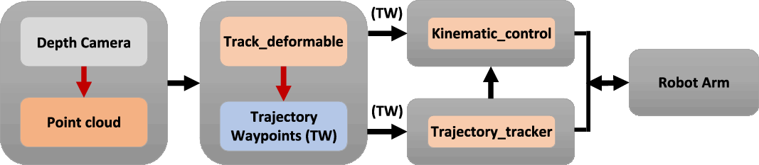
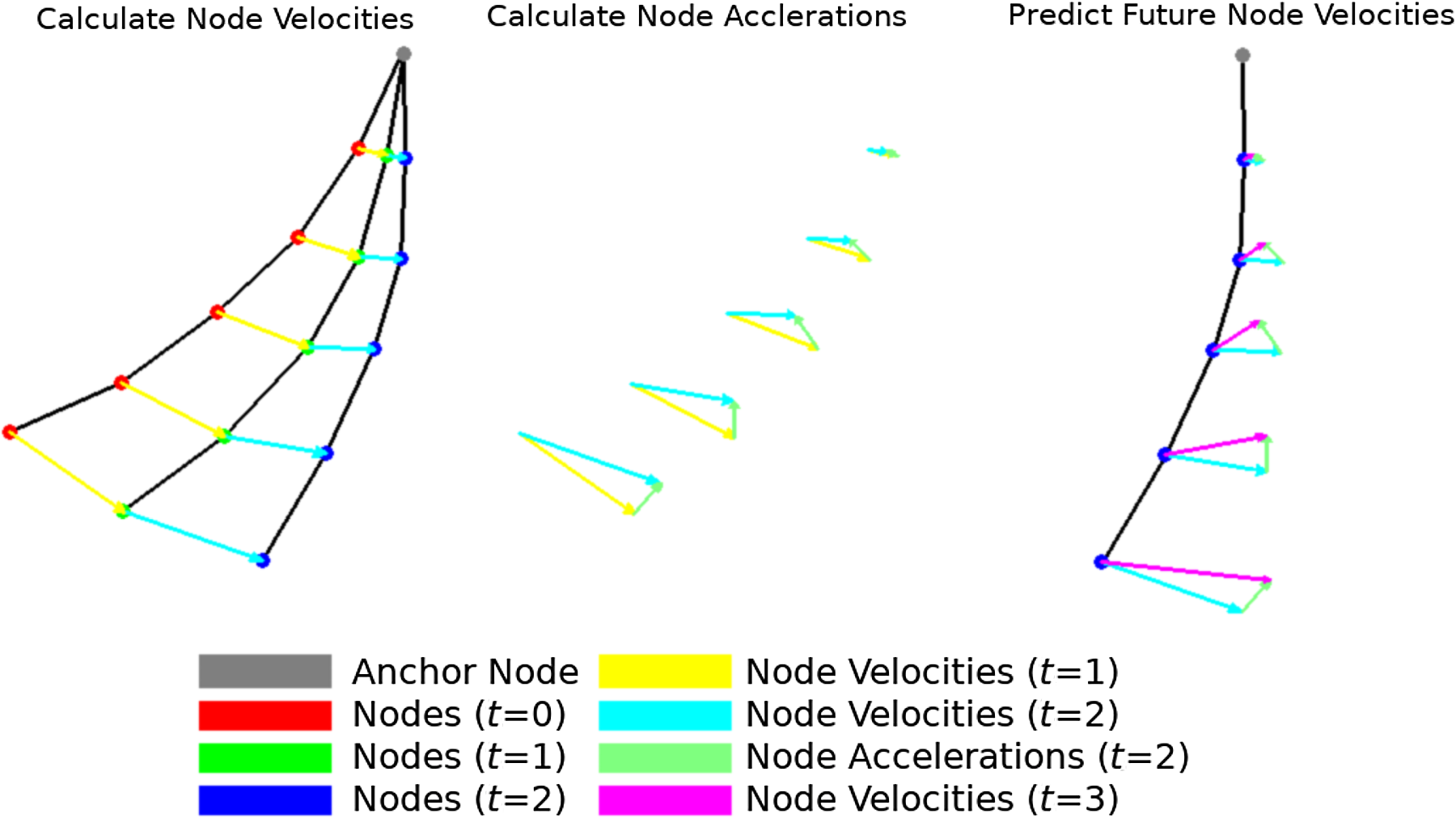
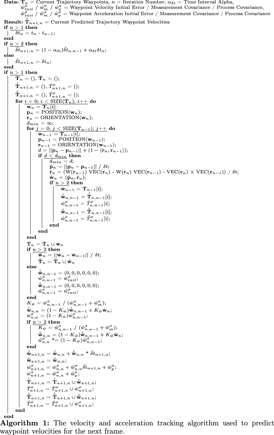
Illustration of the velocity/acceleration tracking process. The difference is calculated between the closest nodes between frames, and this combined with the timestamp difference gives each node’s velocity across the last frame. This process is then repeated with subsequent velocities to derive an acceleration across frames for each node. Finally, the velocity and acceleration for each node can be combined to form a prediction of what the velocity will be for the next frame. In this example, the distances are much larger than what would typically be seen and the use of Kalman filters is not included as part of the illustration.
4.1. Slicing
The approach we take to separate $\mathbf{O}$
into
$\mathbf{O}$
into $\mathbf{N}^O_f$
is to repeatedly bisect or “slice” the sub-pointclouds along their direction of greatest variance until a suitable variable has been reached, based on Assumption 4. This technique is inspired by viewing the LDO as a long object which we want to cut up with a knife (e.g. dough, a sausage). However, we further refine this view by always bisecting, as opposed to working our way along the LDO slicing as we go. This results in the maximum number of slices needed to reach a final node sub-pointcloud S being of complexity
$\mathbf{N}^O_f$
is to repeatedly bisect or “slice” the sub-pointclouds along their direction of greatest variance until a suitable variable has been reached, based on Assumption 4. This technique is inspired by viewing the LDO as a long object which we want to cut up with a knife (e.g. dough, a sausage). However, we further refine this view by always bisecting, as opposed to working our way along the LDO slicing as we go. This results in the maximum number of slices needed to reach a final node sub-pointcloud S being of complexity $O(\log_2 |\mathbf{O}|)$
. Meanwhile, the time complexity of the approach is
$O(\log_2 |\mathbf{O}|)$
. Meanwhile, the time complexity of the approach is $O(2^{S-1})$
. This ultimately results in an
$O(2^{S-1})$
. This ultimately results in an $O(|\mathbf{O}|)$
time complexity, suitable for application with pointclouds of varying resolution.
$O(|\mathbf{O}|)$
time complexity, suitable for application with pointclouds of varying resolution.
The proposed method first initialises $\mathbf{N}^O$
with
$\mathbf{N}^O$
with $\mathbf{O}$
:
$\mathbf{O}$
:
 \begin{equation} \mathbf{N}^O_0 = \{ \mathbf{O} \}\end{equation}
For each iteration of the algorithm, given the node sub-pointclouds $\mathbf{N}^O$
the corresponding node positions
$\mathbf{N}^O$
the corresponding node positions $\mathbf{N}^x$
and covariance matrix trace values
$\mathbf{N}^x$
and covariance matrix trace values $\mathbf{N}^\sigma$
are calculated:
$\mathbf{N}^\sigma$
are calculated:
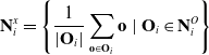 \begin{equation} \mathbf{N}^x_i = \left\{ \frac{1}{|\mathbf{O}_{i}|} \sum_{\mathbf{o} \in \mathbf{O}_{i}} \mathbf{o}\ |\ \mathbf{O}_{i} \in \mathbf{N}^O_i \right\}\end{equation}
 \begin{equation} \mathbf{N}^\sigma_i = \{ {\rm tr}(\Sigma(\mathbf{O}_{i}))\ |\ \mathbf{O}_{i} \in \mathbf{N}^O_i \}\end{equation}
 \begin{equation} \mathbf{N}_i = (\mathbf{N}^x_i, \mathbf{N}^O_i, \mathbf{N}^\sigma_i)\end{equation}
where $tr(\!\cdot\!)$
is the matrix trace and
$tr(\!\cdot\!)$
is the matrix trace and $\Sigma(\!\cdot\!)$
is the covariance matrix. Next, the node with the greatest covariance matrix trace value is determined:
$\Sigma(\!\cdot\!)$
is the covariance matrix. Next, the node with the greatest covariance matrix trace value is determined:
 \begin{equation} \hat{\mathbf{N}}_i = (\hat{\mathbf{x}}_i, \hat{\mathbf{O}}_i, \hat{\sigma}_i) = \mathop{\rm arg\,max}_{(\mathbf{x}_i, \mathbf{O}_i, \sigma_i) \in \mathbf{N}_i} \sigma_i\end{equation}
We bisect this node through $\hat{\mathbf{x}}_i$
perpendicular to the direction of the first component vector
$\hat{\mathbf{x}}_i$
perpendicular to the direction of the first component vector $\mathbf{v}_\lambda$
derived from the principal component analysis (PCA) of
$\mathbf{v}_\lambda$
derived from the principal component analysis (PCA) of $\hat{\mathbf{O}}_i$
:
$\hat{\mathbf{O}}_i$
:
 \begin{equation} \hat{\mathbf{O}}_{i,0} = \{ \mathbf{o} \in \hat{\mathbf{O}}_i\ |\ \langle \mathbf{o} - \hat{\mathbf{x}}_i, \mathbf{v}_\lambda \rangle \geq 0 \}\end{equation}
 \begin{equation} \hat{\mathbf{O}}_{i,1} = \{ \mathbf{o} \in \hat{\mathbf{O}}_i\ |\ \langle \mathbf{o} - \hat{\mathbf{x}}_i, \mathbf{v}_\lambda \rangle < 0 \}\end{equation}
From the two resulting sub-pointclouds, the next iteration is initialised:
 \begin{equation} \mathbf{N}^O_{i+1} = ( \mathbf{N}^O_{i} \setminus \{ \hat{\mathbf{O}}_i \} ) \cup \{ \hat{\mathbf{O}}_{i,0}, \hat{\mathbf{O}}_{i,1} \}\end{equation}
The iterations continue until the following condition is met:
 \begin{equation} \forall \sigma_{i} \in \mathbf{N}^\sigma_i : \sigma_{i} \leq \delta_\sigma\end{equation}
This results in all the members of $\mathbf{O}_i \in \mathbf{N}^O$
eventually having a covariance matrix trace
$\mathbf{O}_i \in \mathbf{N}^O$
eventually having a covariance matrix trace $\sigma_i$
below
$\sigma_i$
below $\delta_\sigma$
and ideally close to
$\delta_\sigma$
and ideally close to $\delta_\sigma$
. In the case where a bisection occurs when
$\delta_\sigma$
. In the case where a bisection occurs when $\sigma_i \gtrapprox \delta_\sigma$
, there is a risk of bisecting tangential to the cable rather than perpendicular to the cable, resulting in a “kink” in the final trajectory. In order to reduce the likelihood of such a kink forming and to remove nodes that may have been created due to the presence of noise, a node filtration is carried out based on the cardinality of the sub-pointclouds:
$\sigma_i \gtrapprox \delta_\sigma$
, there is a risk of bisecting tangential to the cable rather than perpendicular to the cable, resulting in a “kink” in the final trajectory. In order to reduce the likelihood of such a kink forming and to remove nodes that may have been created due to the presence of noise, a node filtration is carried out based on the cardinality of the sub-pointclouds:
 \begin{equation} \mathbf{N}^O_f = \{ \mathbf{O}_{n} \in \mathbf{N}^O_n\ |\ |\mathbf{O}_{n}| \geq \delta_O \}\end{equation}
where $\mathbf{N}^O_n$
corresponds to the node sub-pointclouds from the final iteration. From here, the node positions
$\mathbf{N}^O_n$
corresponds to the node sub-pointclouds from the final iteration. From here, the node positions $\mathbf{N}^x_f$
can be calculated, via the following:
$\mathbf{N}^x_f$
can be calculated, via the following:
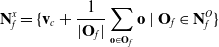 \begin{equation} \mathbf{N}^x_f = \{ \mathbf{v}_c + \frac{1}{|\mathbf{O}_{f}|} \sum_{\mathbf{o} \in \mathbf{O}_{f}} \mathbf{o}\ |\ \mathbf{O}_{f} \in \mathbf{N}^O_f \}\end{equation}
where $\mathbf{v}_c$
is a constant pre-defined translation vector used to accommodate for the error introduced by
$\mathbf{v}_c$
is a constant pre-defined translation vector used to accommodate for the error introduced by $\mathbf{O}$
being projected only on one side of the LDO.
$\mathbf{O}$
being projected only on one side of the LDO.
4.2. Trajectory creation
Once the nodes have been derived using the slicing algorithm, a trajectory representation can be created. We effectively want the trajectory to begin at a node at one end of the LDO and pass through each node in the correct order. To do this, the first waypoint node is determined with the following optimisation:
 \begin{equation}\mathbf{T}^N_0 = \mathop{\rm arg\,max}_{\mathbf{x}_f \in \mathbf{N}^x_f}\ - \langle\mathbf{R}^Y_C, \mathbf{x}_f \rangle\ + \sum_{\mathbf{x}_f^\prime \in \mathbf{N}^x} || \mathbf{x}_f - \mathbf{x}_f^\prime ||\end{equation}
where $\mathbf{R}^Y_C$
is the Y axis of the depth camera. This equation aims to find the node which is the greatest distance from all other nodes while preferencing nodes towards the top of the camera’s view. This preference is to increase the stability in terms of which end of the LDO is selected for the starting node. However, this preferencing is based on the assumption of a vertically aligned LDO, so this may require adjustment on circumstance. For example, rather than using a dot product-based metric, the preferencing could take into account the distance from the robot’s manipulator to each prospective node. Each successive node is then determined by another set of optimisations as follows:
$\mathbf{R}^Y_C$
is the Y axis of the depth camera. This equation aims to find the node which is the greatest distance from all other nodes while preferencing nodes towards the top of the camera’s view. This preference is to increase the stability in terms of which end of the LDO is selected for the starting node. However, this preferencing is based on the assumption of a vertically aligned LDO, so this may require adjustment on circumstance. For example, rather than using a dot product-based metric, the preferencing could take into account the distance from the robot’s manipulator to each prospective node. Each successive node is then determined by another set of optimisations as follows:
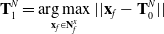 \begin{equation} \mathbf{T}^N_{1} = \mathop{\rm arg\,max}_{\mathbf{x}_f \in \mathbf{N}^x_f} || \mathbf{x}_f - \mathbf{T}^N_0 ||\end{equation}
 \begin{equation} \mathbf{T}^N_{i+1} = \mathop{\rm arg\,max}_{\mathbf{x}_f \in \mathbf{N}^x_f} \ln (|| \mathbf{x}_f - \mathbf{T}^N_i ||) + \langle \mathbf{T}^N_i - \mathbf{T}^N_{i-1}, \mathbf{x}_f - \mathbf{T}^N_i \rangle\end{equation}
Here, the second waypoint node is determined simply as the closest node to the first waypoint node based on $L^2$
distance. The subsequent waypoint nodes are determined via a combination of
$L^2$
distance. The subsequent waypoint nodes are determined via a combination of $L^2$
distance and the exponent of the dot product between the new and previous directions of the trajectory (i.e.
$L^2$
distance and the exponent of the dot product between the new and previous directions of the trajectory (i.e. $\mathbf{x}_f - \mathbf{T}^N_i$
and
$\mathbf{x}_f - \mathbf{T}^N_i$
and $\mathbf{T}^N_i - \mathbf{T}^N_{i-1}$
, respectively). However, for ease of reading, the function being maximised has been shifted into logarithmic space. Since the logarithmic function is strictly increasing it does not impact the result of the
$\mathbf{T}^N_i - \mathbf{T}^N_{i-1}$
, respectively). However, for ease of reading, the function being maximised has been shifted into logarithmic space. Since the logarithmic function is strictly increasing it does not impact the result of the $arg\,max$
operation, but it does make interpreting the dot product exponent easier.
$arg\,max$
operation, but it does make interpreting the dot product exponent easier.
Once the order of nodes has been determined, spline interpolation is used to smooth the transition between nodes to produce a trajectory $\mathbf{T}$
. This trajectory is in turn composed of a series of waypoints
$\mathbf{T}$
. This trajectory is in turn composed of a series of waypoints $\mathbf{w} \in \mathbf{T}$
. Then an orientation is derived for each waypoint frame in the trajectory. For the
$\mathbf{w} \in \mathbf{T}$
. Then an orientation is derived for each waypoint frame in the trajectory. For the $i{\rm th}$
waypoint in the trajectory
$i{\rm th}$
waypoint in the trajectory $\mathbf{w}_i$
with position
$\mathbf{w}_i$
with position $\mathbf{p}_i$
, the rotation matrix’s columns
$\mathbf{p}_i$
, the rotation matrix’s columns $\mathbf{R}_i = (\mathbf{R}^X_i, \mathbf{R}^Y_i, \mathbf{R}^Z_i)$
are determined as follows:
$\mathbf{R}_i = (\mathbf{R}^X_i, \mathbf{R}^Y_i, \mathbf{R}^Z_i)$
are determined as follows:
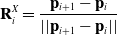 \begin{equation} \mathbf{R}^X_i = \frac{\mathbf{p}_{i+1} - \mathbf{p}_i}{|| \mathbf{p}_{i+1} - \mathbf{p}_i ||}\end{equation}
The convention of having the X axis as the frontal facing axis is followed, aligning the axis with the direction of travel for the waypoints. For the case that $\mathbf{w}_i$
is the final waypoint in the chain, there is no
$\mathbf{w}_i$
is the final waypoint in the chain, there is no $\mathbf{w}_{i+1}$
therefore set
$\mathbf{w}_{i+1}$
therefore set $\mathbf{R}^X_i = \mathbf{R}^X_{i-1}$
:
$\mathbf{R}^X_i = \mathbf{R}^X_{i-1}$
:
 \begin{equation} \mathbf{R}^Y_i = \mathbf{R}^X_i \times \mathbf{R}^Z_C\end{equation}
 \begin{equation} \mathbf{R}^Z_i = \mathbf{R}^X_i \times \mathbf{R}^Y_i\end{equation}
where $\mathbf{R}^Z_C$
is the Z axis of the depth camera. The aim here is to line up the Z axis of the waypoints with the Z axis of a robot arm’s end effector which assists with the kinematic control system integration/experimentation discussed in the following sections. The rotation matrix
$\mathbf{R}^Z_C$
is the Z axis of the depth camera. The aim here is to line up the Z axis of the waypoints with the Z axis of a robot arm’s end effector which assists with the kinematic control system integration/experimentation discussed in the following sections. The rotation matrix $\mathbf{R}_i$
for each waypoint is then converted into a quaternion
$\mathbf{R}_i$
for each waypoint is then converted into a quaternion $\mathbf{r}_i$
in preparation for calculations the velocity and acceleration tracking and the robot arm control will need to make. Each waypoint position and quaternion will combine to define a pose for each waypoint which collectively describe the state of the LDO.
$\mathbf{r}_i$
in preparation for calculations the velocity and acceleration tracking and the robot arm control will need to make. Each waypoint position and quaternion will combine to define a pose for each waypoint which collectively describe the state of the LDO.
5. Integration with a Kinematic Control System
This section discusses the integration of the proposed tracking approach into a kinematic control system. This corresponds to the “trajectory_tracker” and “kinematic_control” nodes of Fig. 1. The following section aims to accomplish three objectives. Firstly to discuss approaches which have been developed in tandem with the proposed approach to increase its effectiveness. Secondly to describe how to approach the task of integrating the proposed approach with a kinematic control system of a 7-DoF redundant robot arm. And finally to define in detail the implementation used for the experimentation involving kinematic control systems (See Case Study 2). To summarise the kinematic control system, its purpose is to track along the length of the LDO as it is in motion. This is a task which requires a high level of precision from the tracking system, as well as minimal latency and appropriate integration. Therefore, the described system acts as a good proof of concept to challenge the tracking technique as a means of validating its efficacy.
5.1. Velocity and acceleration tracking
While tracking the node positions for a deformable object is sufficient for determining the current configuration of the object, it poses a problem for systems with non-quasistatic properties. If a control system just attempts to follow a trajectory based off of nodes generated with the proposed method, then there will always be an inherent error involved in the tracing task. This is because a system which only uses the current position of the nodes can only adapt to motion in the system once the motion has already occurred. A fast feedback loop can help to mitigate this problem, but such an approach makes no real attempt to proactively account for the future motion of the deformable linear object.
Algorithm 1 provides detailed pseudocode of our means of proactively reacting to future motion by approximating the expected velocity and acceleration of each trajectory waypoint. This way, future motion can be accounted for by the kinematic control system via adjusting the end effector’s desired velocity.
5.2. Robotic arm control
Having described a means to plan a trajectory and estimate the expected velocity of its waypoints, it is finally possible to integrate this data with a kinematic control system. The control system we use focuses on moving to the next waypoint in the chain in order to trace the length of the object with the end effector. The next waypoint is initially set to the first waypoint in the chain, after reaching this point the end effector will attempt to move towards the first viable waypoint as defined as fulfilling the following three conditions:
 \begin{equation} \langle \mathbf{R}_E^X, \mathbf{p}_i - \mathbf{p}_E \rangle \geq 0\end{equation}
 \begin{equation} \langle \mathbf{R}_E^X, \mathbf{R}_i^X \rangle \geq 0\end{equation}
 \begin{equation} || \mathbf{p}_i - \mathbf{p}_E || \geq \delta_p\end{equation}
where $\mathbf{p}_E$
and
$\mathbf{p}_E$
and $\mathbf{R}_E^X$
are the position and X axis column of the rotation matrix for the end effector. Meanwhile,
$\mathbf{R}_E^X$
are the position and X axis column of the rotation matrix for the end effector. Meanwhile, $\mathbf{p}_i$
is the position of waypoint
$\mathbf{p}_i$
is the position of waypoint $\mathbf{w}_i$
and
$\mathbf{w}_i$
and $\delta_p$
is a linear distance threshold. Unlike the velocity and acceleration tracking, there is no concept of timesteps here, hence the difference in notation. These three conditions can be summarised as 1. Ensure the linear velocity vector to reach the waypoint approximately matches the current orientation of the end effector, 2. Ensure the orientation of the waypoint has approximately the same orientation as the end effector currently, 3. Ensure the waypoint is sufficiently far away from the end effector.
$\delta_p$
is a linear distance threshold. Unlike the velocity and acceleration tracking, there is no concept of timesteps here, hence the difference in notation. These three conditions can be summarised as 1. Ensure the linear velocity vector to reach the waypoint approximately matches the current orientation of the end effector, 2. Ensure the orientation of the waypoint has approximately the same orientation as the end effector currently, 3. Ensure the waypoint is sufficiently far away from the end effector.
The desired end effector velocity $\mathbf{v}$
is calculated as a combination of the difference between the end effector and its next waypoint
$\mathbf{v}$
is calculated as a combination of the difference between the end effector and its next waypoint $\Delta \mathbf{x}$
and the predicted velocities for the waypoint calculated previously
$\Delta \mathbf{x}$
and the predicted velocities for the waypoint calculated previously $\hat{\dot{\mathbf{x}}}$
:
$\hat{\dot{\mathbf{x}}}$
:
 \begin{equation} \mathbf{v} = \alpha\,\Delta \mathbf{x} + \beta \hat{\dot{\mathbf{x}}}\end{equation}
where $\alpha$
is the gain used to determine the waypoint approach velocity and
$\alpha$
is the gain used to determine the waypoint approach velocity and $\beta$
is the gain for the expected waypoint velocity.
$\beta$
is the gain for the expected waypoint velocity. $\beta$
must be tuned to account for systems in which high jerk is present. Meanwhile, as for
$\beta$
must be tuned to account for systems in which high jerk is present. Meanwhile, as for $\alpha$
it is calculated from a modified adaptive gain algorithm from the ViSP library [Reference Marchand, Spindler and Chaumette28]:
$\alpha$
it is calculated from a modified adaptive gain algorithm from the ViSP library [Reference Marchand, Spindler and Chaumette28]:
 \begin{equation}\alpha = (\lambda_0 - \lambda_\infty) e^{-\frac{{\dot{\lambda}}_0 }{\lambda_0 - \lambda_\infty} ||\Delta \mathbf{x}||} + \lambda_\infty\end{equation}
where $\lambda_0$
is the gain value when
$\lambda_0$
is the gain value when $||\Delta \mathbf{x}||$
is near zero,
$||\Delta \mathbf{x}||$
is near zero, $\lambda_\infty$
is the gain value when
$\lambda_\infty$
is the gain value when $||\Delta \mathbf{x}||$
is near infinity and
$||\Delta \mathbf{x}||$
is near infinity and ${\dot{\lambda}}_0$
is the rate of change for the gain when
${\dot{\lambda}}_0$
is the rate of change for the gain when $||\Delta \mathbf{x}||$
is near zero. All three of these parameters must be tuned for the system present.
$||\Delta \mathbf{x}||$
is near zero. All three of these parameters must be tuned for the system present.
In addition to the desired end effector Cartesian velocity $\mathbf{v}$
, we also calculate secondary objective desired joint velocities
$\mathbf{v}$
, we also calculate secondary objective desired joint velocities $\dot{\mathbf{q}}_d$
as follows:
$\dot{\mathbf{q}}_d$
as follows:
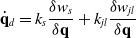 \begin{equation} \dot{\mathbf{q}}_d = k_s \frac{\delta w_s}{\delta \mathbf{q}} + k_{jl} \frac{\delta w_{jl}}{\delta \mathbf{q}}\end{equation}
where $w_s$
is the measure of manipulability proposed by Yoshikawa et al. [Reference Yoshikawa29],
$w_s$
is the measure of manipulability proposed by Yoshikawa et al. [Reference Yoshikawa29], $w_{jl}$
is a measure of how close the current joint configuration is to the joint limits, and
$w_{jl}$
is a measure of how close the current joint configuration is to the joint limits, and $k_s$
and
$k_s$
and $k_{jl}$
are the respective weightings for each of these measures.
$k_{jl}$
are the respective weightings for each of these measures.
The derivative of the measure of manipulability $w_s$
with respect to the joint states is used as a means to avoid joint configurations that would result in a singularity:
$w_s$
with respect to the joint states is used as a means to avoid joint configurations that would result in a singularity:
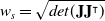 \begin{equation} w_s = \sqrt{det(\mathbf{J}\mathbf{J}^\intercal)}\end{equation}
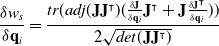 \begin{equation} \frac{\delta w_s}{\delta \mathbf{q}_i} = \frac{tr(adj(\mathbf{J}\mathbf{J}^\intercal) (\frac{\delta \mathbf{J}}{\delta \mathbf{q}_i} \mathbf{J}^\intercal + \mathbf{J} \frac{\delta \mathbf{J}^\intercal}{\delta \mathbf{q}_i}))}{2 \sqrt{det(\mathbf{J}\mathbf{J}^\intercal)}}\end{equation}
Meanwhile, the derivative of $w_{jl}$
with respect to the joint states is used to avoid joint limits using the maximum and minimum limits for each joint
$w_{jl}$
with respect to the joint states is used to avoid joint limits using the maximum and minimum limits for each joint $\mathbf{q}_i^{\max}$
and
$\mathbf{q}_i^{\max}$
and $\mathbf{q}_i^{\min}$
:
$\mathbf{q}_i^{\min}$
:
 \begin{equation} w_{jl} = -\frac{1}{2} \sum_{i = 0}^n \left(\frac{2 \mathbf{q}_i - (\mathbf{q}_i^{\max} + \mathbf{q}_i^{\min})}{2 (\mathbf{q}_i^{\max} - \mathbf{q}_i^{\min})}\right)^2\end{equation}
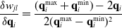 \begin{equation} \frac{\delta w_{jl}}{\delta \mathbf{q}_i} = \frac{(\mathbf{q}_i^{\max} + \mathbf{q}_i^{\min}) - 2 \mathbf{q}_i}{2 (\mathbf{q}_i^{\max} - \mathbf{q}_i^{\min})^2}\end{equation}
Having calculated both desired end effector Cartesian velocity $\mathbf{v}$
and secondary objective desired joint velocities
$\mathbf{v}$
and secondary objective desired joint velocities $\mathbf{q}_d$
, the output joint velocities are calculated as follows:
$\mathbf{q}_d$
, the output joint velocities are calculated as follows:
 \begin{equation} \dot{\mathbf{q}} = \mathbf{J}^+ \mathbf{v} + (\mathbf{I} - \mathbf{J}^+ \mathbf{J})\ \dot{\mathbf{q}_d}\end{equation}
where $\mathbf{I}$
is the identity matrix,
$\mathbf{I}$
is the identity matrix, $\mathbf{J}$
is the robot arm’s Jacobian matrix and
$\mathbf{J}$
is the robot arm’s Jacobian matrix and $\mathbf{J}^+$
is its pseudoinverse. As previously mentioned, the end effector velocities take precedence and so
$\mathbf{J}^+$
is its pseudoinverse. As previously mentioned, the end effector velocities take precedence and so $\mathbf{q}_d$
is projected into null space using
$\mathbf{q}_d$
is projected into null space using $(\mathbf{I} - \mathbf{J}^+ \mathbf{J})$
as a secondary objective.
$(\mathbf{I} - \mathbf{J}^+ \mathbf{J})$
as a secondary objective.
The task will complete when there are no more viable waypoints available. This allows for a smoother tracing motion by avoiding the need for the end effector to return to a waypoint that is narrowly missed. This approach does have the downside that if there are no more viable waypoints available due to the end effector moving too far from the object, then the procedure will prematurely terminate. Automatic detection of such cases could be carried out by measuring the distance from the end effector to the final waypoint on task completion or by considering a mean, total or root mean square of error over time. However, due to this kinematic control system’s use as a proof of concept, the implementation and analysis of such automatic detection are not covered here.
6. Experiments
Here, we present three experiments and provide discussion on the proposed approach based on the results. The first experiment aims to determine the accuracy of the slicing-based tracking approach in simulation where custom conditions can be easily defined. The second experiment extends the first experiment by measuring the accuracy of a kinematic control system that has been integrated with the proposed approach. The third experiment aims to validate the findings of the first simulation experiment with a real-world experiment. Prior to discuss the case studies, it will be explained how the pointclouds were captured and filtered.
6.1. Pointcloud capture and filtering
In order to capture a pointcloud $\mathbf{O}$
of the scene in which the LDO is situated, a depth camera is used. Prior to carrying out tracking, any irrelevant points should be removed from
$\mathbf{O}$
of the scene in which the LDO is situated, a depth camera is used. Prior to carrying out tracking, any irrelevant points should be removed from $\mathbf{O}$
. We utilised a positional filter combined with a CIELAB colour space filter [30] to obtain just the points of the tracked LDO. The CIELAB colour space was selected for our experiments based on an analysis of the ease of filtering the colour distribution for the object’s colour in each colour space. Any combination of filters or means of segmentation could be used here instead in order to obtain the set of points relevant to the object. However, the process of determining which filters ought to be applied is beyond the scope of this work.
$\mathbf{O}$
. We utilised a positional filter combined with a CIELAB colour space filter [30] to obtain just the points of the tracked LDO. The CIELAB colour space was selected for our experiments based on an analysis of the ease of filtering the colour distribution for the object’s colour in each colour space. Any combination of filters or means of segmentation could be used here instead in order to obtain the set of points relevant to the object. However, the process of determining which filters ought to be applied is beyond the scope of this work.
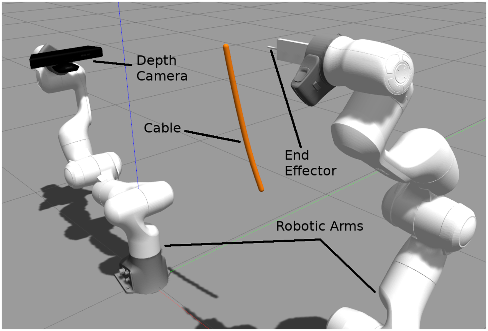
Screenshot of the simulation set-up used during experiments. Two 7-DoF redundant cobots (Franka Emika) are used where an RGB-D camera (Kinect) is mounted on one of the cobots (with eye-to-hand configuration) to provide the sensory data used by the proposed tracking approach. In this work, the depth camera arm remains static.
6.2. Case study 1: Tracking a deformable object in simulation
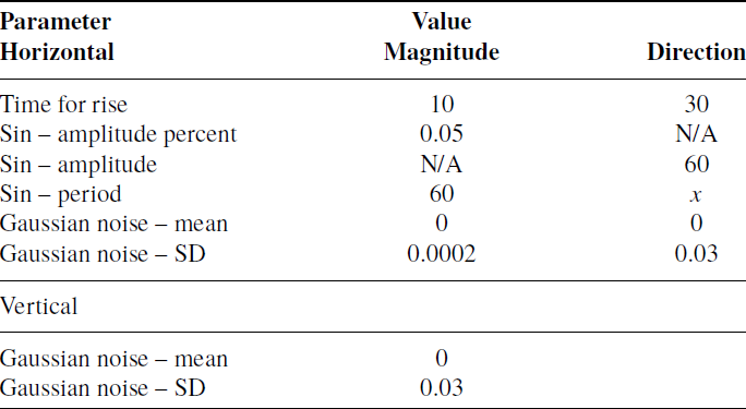
In this experiment, we aim to establish the accuracy of the tracking method under various kinematic conditions. This is done without consideration for any form of kinematic control system integration and is carried out in simulation to lower the risk of confounding variables. In order to establish the accuracy, a LDO was simulated in the Gazebo simulator v9.0.0 using a series of 10 pill-shaped links each $1.5 \times 1.5 \times 5.5\,$
cm (See Fig. 3). The cable was made to sway by utilising the wind physics of Gazebo. A wind velocity of
$1.5 \times 1.5 \times 5.5\,$
cm (See Fig. 3). The cable was made to sway by utilising the wind physics of Gazebo. A wind velocity of $1\,\mathrm{m/s}$
was applied parallel to the X axis with other parameters of the wind defined as shown in Table I. In this table, x refers to the independent variable that we controlled throughout the experiment. The values were derived from
$1\,\mathrm{m/s}$
was applied parallel to the X axis with other parameters of the wind defined as shown in Table I. In this table, x refers to the independent variable that we controlled throughout the experiment. The values were derived from $x = 1 / f$
where f is the frequency of the wind direction completing a period, varying from
$x = 1 / f$
where f is the frequency of the wind direction completing a period, varying from $0\,\mathrm{Hz}$
to
$0\,\mathrm{Hz}$
to $1.6\,\mathrm{Hz}$
inclusive. For a frequency of
$1.6\,\mathrm{Hz}$
inclusive. For a frequency of $0\,\mathrm{Hz}$
, the wind physics were simply disabled resulting in no movement in the cable.
$0\,\mathrm{Hz}$
, the wind physics were simply disabled resulting in no movement in the cable.
In order to measure the tracking accuracy, every $0.1\,\mathrm{s}$
in simulation time the most recent trajectory generated from tracking was compared with the ground truth. The ground truth trajectory was calculated as a series of straight lines connecting the start position, joint positions and end position of the cable. The linear error was calculated as the Euclidean distance from projecting from each waypoint to the ground truth trajectory. Meanwhile, given a waypoint the angular error was calculated by applying
$0.1\,\mathrm{s}$
in simulation time the most recent trajectory generated from tracking was compared with the ground truth. The ground truth trajectory was calculated as a series of straight lines connecting the start position, joint positions and end position of the cable. The linear error was calculated as the Euclidean distance from projecting from each waypoint to the ground truth trajectory. Meanwhile, given a waypoint the angular error was calculated by applying ${\cos}^{-1}(2{\langle \mathbf{r}_1, \mathbf{r}_2 \rangle}^2 - 1)$
to the waypoint orientation and the ground truth orientation, both in quaternion form. The ground truth orientation is calculated here as the orientation at the point resulting from the projection of the waypoint onto the ground truth trajectory. The orientation at a given point along the ground truth trajectory is based on the orientation of the link in the simulation corresponding to that part of the ground truth trajectory.
${\cos}^{-1}(2{\langle \mathbf{r}_1, \mathbf{r}_2 \rangle}^2 - 1)$
to the waypoint orientation and the ground truth orientation, both in quaternion form. The ground truth orientation is calculated here as the orientation at the point resulting from the projection of the waypoint onto the ground truth trajectory. The orientation at a given point along the ground truth trajectory is based on the orientation of the link in the simulation corresponding to that part of the ground truth trajectory.
The mean was then calculated for linear and angular error across all waypoints for that reading. This was carried out for a total period of $300\,\mathrm{s}$
in simulation time for a total of 3000 readings, across which mean and standard deviation were calculated for linear and angular error.
$300\,\mathrm{s}$
in simulation time for a total of 3000 readings, across which mean and standard deviation were calculated for linear and angular error.
Gazebo’s wind parameters.
To provide a basis for comparison with other contemporary deformable object tracking techniques, we perform this experiment with both the original approach of this paper and the tracking approach of Schulman et al. [Reference Schulman, Lee, Ho and Abbeel6]. However, it should be noted that since this approach only offers positional data, no angular error can be calculated for this approach.
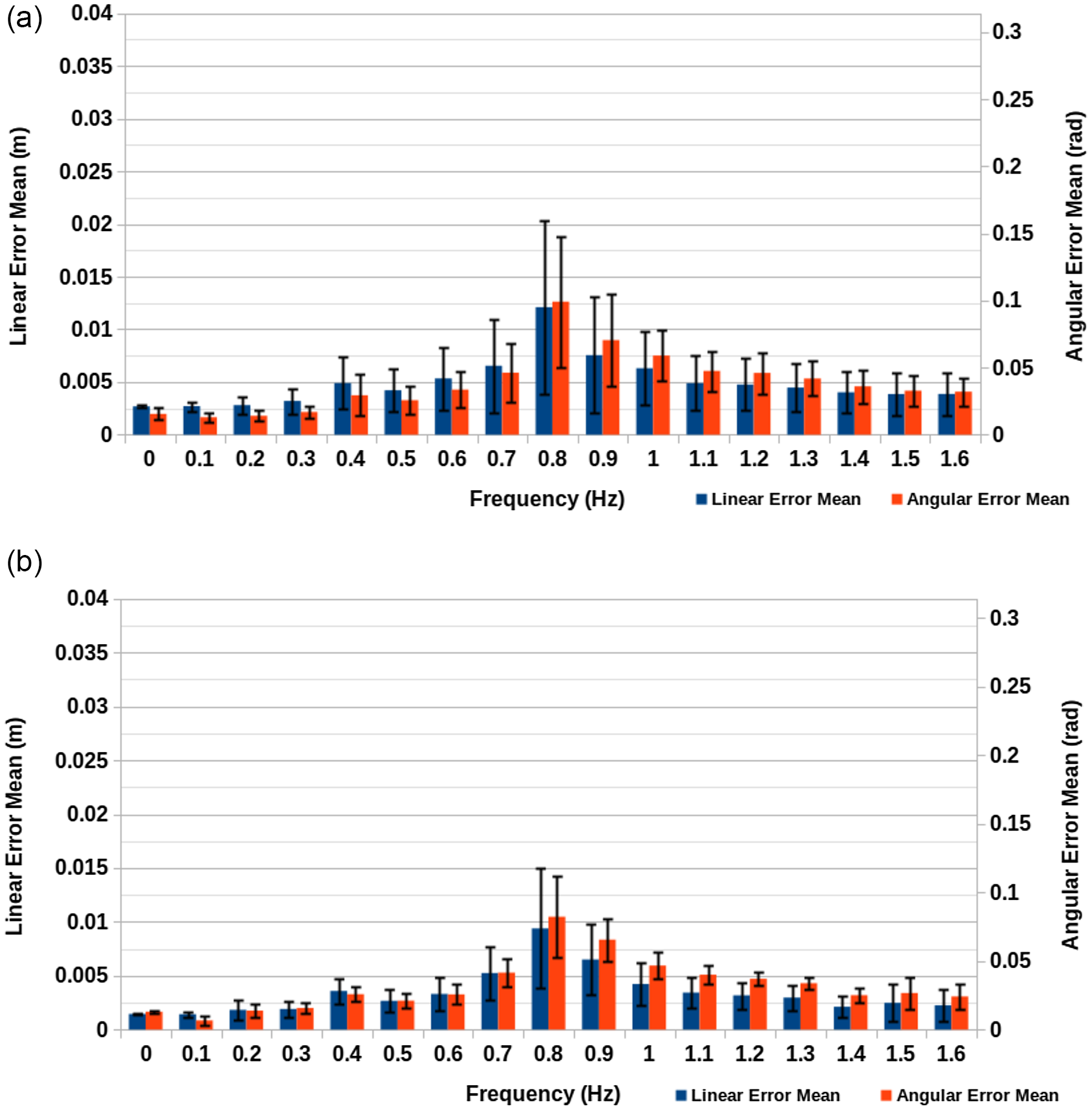
Simulation tracking accuracy results for original approach. (a) Real-time simulation speed at 30 fps with $480 \times 360$
resolution. (b) 10% of real-time simulation speed at 60 fps with
$480 \times 360$
resolution. (b) 10% of real-time simulation speed at 60 fps with $1280 \times 720$
resolution.
$1280 \times 720$
resolution.
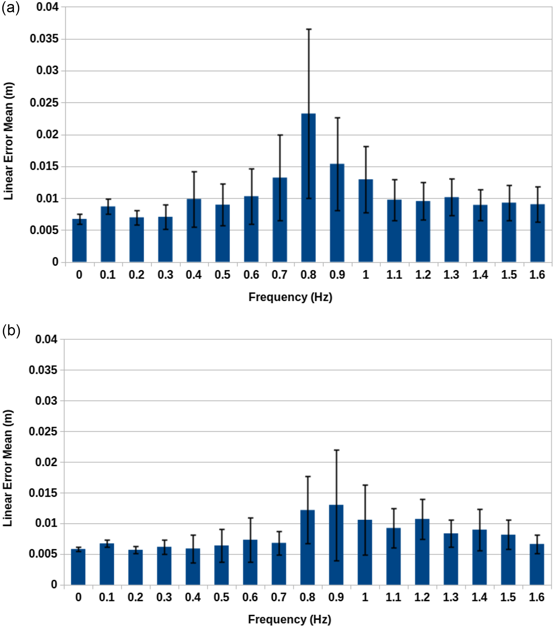
Simulation tracking accuracy results for Schulman et al. approach. (a) Real-time simulation speed at 30 fps with $480 \times 360$
resolution. (b) 10% of real-time simulation speed at 60 fps with
$480 \times 360$
resolution. (b) 10% of real-time simulation speed at 60 fps with $1280 \times 720$
resolution.
$1280 \times 720$
resolution.
Additionally, the entire experiment was repeated twice, once with real-time simulation speed at 30 frames per second (FPS) with $480 \times 360$
resolution and again with 10% of real-time simulation speed at 60 FPS with
$480 \times 360$
resolution and again with 10% of real-time simulation speed at 60 FPS with $1280 \times 720$
resolution. The purpose of repeating the simulation twice was to demonstrate the impact of both latency and low resolution on the algorithm’s performance with the intention of laying out a path for future improvements to the accuracy of the approach. For the purpose of comparison, all parts of the proposed approach were implemented to run on a single thread and experiments were carried out on a Dell XPS 15 9550 laptop with
$1280 \times 720$
resolution. The purpose of repeating the simulation twice was to demonstrate the impact of both latency and low resolution on the algorithm’s performance with the intention of laying out a path for future improvements to the accuracy of the approach. For the purpose of comparison, all parts of the proposed approach were implemented to run on a single thread and experiments were carried out on a Dell XPS 15 9550 laptop with $16\,\mathrm{GB}$
of RAM and an Intel Core i7-6700HQ processor.
$16\,\mathrm{GB}$
of RAM and an Intel Core i7-6700HQ processor.
An important aspect to consider when looking at the angular error is that the ground truth orientations are determined by the orientations of the 10 links making up the cable. Therefore, the ground truth trajectory contains 10 orientations which make no attempt to smooth the change in orientation between them, whereas the waypoints of the tracked trajectory do. This is done in order to make the trajectory more suitable for the kinematic control system experimented with in the next subsection. The result of these circumstances is that in both experiments, the overall angular error is artificially inflated.
Figure 4(a) and (b) show both sets of results for the original approach of this paper, each of which peak at $0.8\,\mathrm{Hz}$
. This is likely the result of
$0.8\,\mathrm{Hz}$
. This is likely the result of $0.8\,\mathrm{Hz}$
being close to the natural frequency of the system and therefore the point at which greatest amplitude is observed. In terms of the difference between the two sets of conditions, we can begin by considering the
$0.8\,\mathrm{Hz}$
being close to the natural frequency of the system and therefore the point at which greatest amplitude is observed. In terms of the difference between the two sets of conditions, we can begin by considering the $0\,\mathrm{Hz}$
case for both. Because there is zero motion in these cases, the camera FPS and simulation speed have no impact, only the camera resolution. Here the
$0\,\mathrm{Hz}$
case for both. Because there is zero motion in these cases, the camera FPS and simulation speed have no impact, only the camera resolution. Here the $480 \times 360$
resolution condition gives a linear error of
$480 \times 360$
resolution condition gives a linear error of $2.69 \pm 0.0892 \times 10^{-3}\,\mathrm{m}$
and an angular error of
$2.69 \pm 0.0892 \times 10^{-3}\,\mathrm{m}$
and an angular error of $1.55 \pm 0.447 \times 10^{-2}\,\mathrm{rad}$
. Meanwhile, the
$1.55 \pm 0.447 \times 10^{-2}\,\mathrm{rad}$
. Meanwhile, the $1280 \times 720$
resolution condition gives a linear error of
$1280 \times 720$
resolution condition gives a linear error of $1.45 \pm 0.0127 \times 10^{-3}\,\mathrm{m}$
and an angular error of
$1.45 \pm 0.0127 \times 10^{-3}\,\mathrm{m}$
and an angular error of $1.30 \pm 0.116 \times 10^{-2}\,\mathrm{rad}$
. As expected, the linear and angular error were reduced by using a higher resolution, demonstrating that one of the limiting factors of the algorithm’s accuracy is the camera resolution in use.
$1.30 \pm 0.116 \times 10^{-2}\,\mathrm{rad}$
. As expected, the linear and angular error were reduced by using a higher resolution, demonstrating that one of the limiting factors of the algorithm’s accuracy is the camera resolution in use.
If we instead look at the largest errors for both conditions, we have a linear error of $1.21 \pm 0.825 \times 10^{-2}\,\mathrm{m}$
versus
$1.21 \pm 0.825 \times 10^{-2}\,\mathrm{m}$
versus $9.38 \pm 5.57 \times 10^{-3}\,\mathrm{m}$
and an angular error of
$9.38 \pm 5.57 \times 10^{-3}\,\mathrm{m}$
and an angular error of $9.91 \pm 4.91 \times 10^{-2}\,\mathrm{rad}$
versus
$9.91 \pm 4.91 \times 10^{-2}\,\mathrm{rad}$
versus $8.22 \pm 3.00 \times 10^{-2}\,\mathrm{rad}$
for the first and second conditions, respectively. By calculating the ratio of differences between the conditions for linear error
$8.22 \pm 3.00 \times 10^{-2}\,\mathrm{rad}$
for the first and second conditions, respectively. By calculating the ratio of differences between the conditions for linear error $(12.1\,\mathrm{mm} - 2.69\,\mathrm{mm})/(9.38\,\mathrm{mm} - 1.55\,\mathrm{mm}) = 1.20$
and angular error
$(12.1\,\mathrm{mm} - 2.69\,\mathrm{mm})/(9.38\,\mathrm{mm} - 1.55\,\mathrm{mm}) = 1.20$
and angular error $(9.91\,\mathrm{mm} - 1.55\,\mathrm{mm})/(8.22\,\mathrm{mm} - 1.30\,\mathrm{mm}) = 1.21$
, we can see that there is a significant impact on the error resulting from an aspect other than the resolution change between the conditions. This result can be attributed to the difference in FPS and real-time factor for the simulation. Higher FPS results in lower latency by reducing the interval between frames and lower real-ime factor reduces latency by reducing computational load. Based on observations made during experimentation latency accounts for a large part of the error, therefore by increasing the FPS of the depth camera and the overall computational ability of the system performing tracking the potential accuracy can be improved.
$(9.91\,\mathrm{mm} - 1.55\,\mathrm{mm})/(8.22\,\mathrm{mm} - 1.30\,\mathrm{mm}) = 1.21$
, we can see that there is a significant impact on the error resulting from an aspect other than the resolution change between the conditions. This result can be attributed to the difference in FPS and real-time factor for the simulation. Higher FPS results in lower latency by reducing the interval between frames and lower real-ime factor reduces latency by reducing computational load. Based on observations made during experimentation latency accounts for a large part of the error, therefore by increasing the FPS of the depth camera and the overall computational ability of the system performing tracking the potential accuracy can be improved.
If we look instead at the results for the Schulman et al. approach shown in Figure 5(a) and (b), we see the results take a similar pattern to those given by this paper’s original approach. However, in both the 100% and 10% real-time simulation speed cases, the results are noticeably worse. In fact, the results given for 10% of real time for the Schulman et al. approach are as bad or worse than the fully real-time results for the original approach of his paper. This demonstrates the suitability of this approach in contrast to existing techniques for deformable object tracking. Here, the increase in error for the Schulman et al. approach can likely be attributed to both increased processing times and erratic behaviour in the underlying simulation of the tracking technique as a result of the high speed of the tracked object.
6.3. Case study 2: Kinematic control system integration experiment
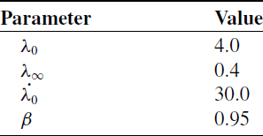
This experiment aims to establish the accuracy of the proposed approach in its entirety as part of a practical task. In terms of the simulation set-up, it was identical to that described in Case Study 1. In this experiment, the proposed tracking approach was combined with the proposed velocity and acceleration tracking and the robot arm control. The parameters used for the robot arm control can be seen in Table II. The end goal is to fully simulate the end effector tracing the length of the tracked object as a proof of concept of integrating the proposed approach with a kinematic control system.
The means of measuring linear and angular error were again identical to Case Study 1, except rather than measuring for every waypoint in the tracked trajectory the error was calculated from the end effector to the ground truth trajectory. In addition, rather than capturing $300\,\mathrm{s}$
worth of records, records were captured for the duration of the tracing motion by the robot. The error readings were recorded for a total of three repeated task executions. Occasionally, it was impossible to project from the end effector onto part of the ground truth trajectory and such readings therefore are marked as having zero linear and angular error. Following the completion of experimentation, these readings were manually removed as well as several readings from the beginning and end of the tracing motions to account for human timing error in starting/stopping the measurement programme. If ever the combined number of readings removed accounted for more than 5% of records for a case, the experimental case was repeated. Similar to Case Study 1 the experiment was repeated twice for the same two conditions.
$300\,\mathrm{s}$
worth of records, records were captured for the duration of the tracing motion by the robot. The error readings were recorded for a total of three repeated task executions. Occasionally, it was impossible to project from the end effector onto part of the ground truth trajectory and such readings therefore are marked as having zero linear and angular error. Following the completion of experimentation, these readings were manually removed as well as several readings from the beginning and end of the tracing motions to account for human timing error in starting/stopping the measurement programme. If ever the combined number of readings removed accounted for more than 5% of records for a case, the experimental case was repeated. Similar to Case Study 1 the experiment was repeated twice for the same two conditions.
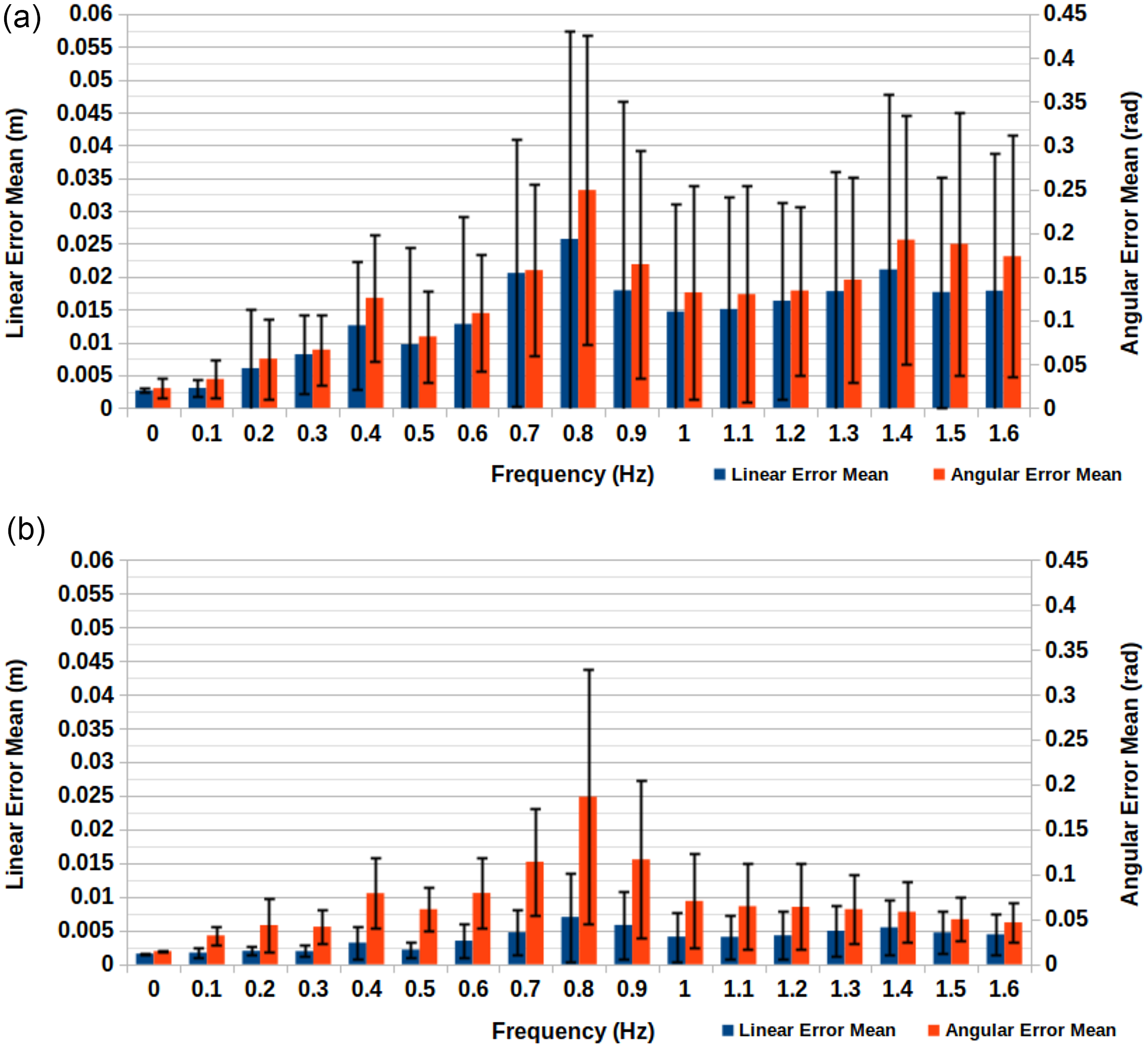
Figure 6(a) and (b) show both sets of results. If we focus on the linear error, the 30 FPS condition’s worst case was $2.58 \pm 3.18 \times 10^{-2}\,\mathrm{m}$
, while the 60 FPS condition’s worst case was
$2.58 \pm 3.18 \times 10^{-2}\,\mathrm{m}$
, while the 60 FPS condition’s worst case was $7.02 \pm 6.58 \times 10^{-3}\,\mathrm{m}$
. Therefore, under the 30 FPS conditions, we see a reduction in accuracy over the previous experiment, while instead under the 60 FPS conditions we see an improvement in accuracy over the previous experiment. The velocity and acceleration tracking has caused the most significant impact here. It is likely the main contributing factor allowing for the approach under the 60 FPS conditions to improve accuracy above that seen during the tracking accuracy experiment. However, this method is also affected by latency to a lesser degree and the necessity of having to move the robot’s end effector rather than just track a trajectory leads the approach to suffer greater than previously in cases involving additional latency. This explains why the 30 FPS conditions display such a drastic difference in linear error and further justifies the use of higher FPS and faster processing capabilities.
$7.02 \pm 6.58 \times 10^{-3}\,\mathrm{m}$
. Therefore, under the 30 FPS conditions, we see a reduction in accuracy over the previous experiment, while instead under the 60 FPS conditions we see an improvement in accuracy over the previous experiment. The velocity and acceleration tracking has caused the most significant impact here. It is likely the main contributing factor allowing for the approach under the 60 FPS conditions to improve accuracy above that seen during the tracking accuracy experiment. However, this method is also affected by latency to a lesser degree and the necessity of having to move the robot’s end effector rather than just track a trajectory leads the approach to suffer greater than previously in cases involving additional latency. This explains why the 30 FPS conditions display such a drastic difference in linear error and further justifies the use of higher FPS and faster processing capabilities.
Robotic arm control parameters.
Kinematic control system accuracy results. (a) Real-time simulation speed at 30 fps with $480 \times 360$
resolution. (b) 10% of real-time simulation speed at 60 fps with
$480 \times 360$
resolution. (b) 10% of real-time simulation speed at 60 fps with $1280 \times 720$
resolution.
$1280 \times 720$
resolution.
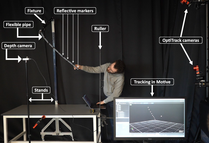
Experimental set-up: position of the reflective markers attached on the cable tracks by the motion capture systems. In addition, depth camera creates the mesh pointcloud of the pipe. Position of the depth camera w.r.t the word coordinate reference is recognised by single reflective marker attached on the depth camera. Motive is the motion capture software associated with the OptiTrack cameras.
Having discussed the linear error, it is worth exploring why the angular error varies less between the differing conditions and why it is noticeably higher here than in Case Study 1. The angular error for the 30 FPS condition’s maximum error case was $2.49 \pm 1.77 \times 10^{-1}\,\mathrm{rad}$
, while for the 60 FPS condition’s maximum error case it was
$2.49 \pm 1.77 \times 10^{-1}\,\mathrm{rad}$
, while for the 60 FPS condition’s maximum error case it was $1.86 \pm 1.42 \times 10^{-1}\,\mathrm{rad}$
. A large contributor to the large angular error is the fact that the desired orientation is determined by the current waypoint. Therefore, if the end effector is following the trajectory at a high velocity, then its desired orientation will change more rapidly which is harder to accommodate for. This combined with the smoothing issue discussed in the previous experiment explain why there is a much greater disparity between linear error values and angular error values between conditions.
$1.86 \pm 1.42 \times 10^{-1}\,\mathrm{rad}$
. A large contributor to the large angular error is the fact that the desired orientation is determined by the current waypoint. Therefore, if the end effector is following the trajectory at a high velocity, then its desired orientation will change more rapidly which is harder to accommodate for. This combined with the smoothing issue discussed in the previous experiment explain why there is a much greater disparity between linear error values and angular error values between conditions.
6.4. Case study 3: Real world experiment
This experiment aims to validate the results of the previous experiment by performing a similar experiment in the real world (Fig. 7). However, due to the difficulty in producing a precisely oscillating wind in the real world, we instead drop a flexible pipe from a series of heights. The pipe is $12.5\,\mathrm{mm}$
in radius and approximately
$12.5\,\mathrm{mm}$
in radius and approximately $70\,\mathrm{cm}$
in length and was affixed to a clamp at one end from which it could swing freely. To produce a ground truth against which we could compare tracking data, eight motion capture markers were attached along the length of the pipe at approximately
$70\,\mathrm{cm}$
in length and was affixed to a clamp at one end from which it could swing freely. To produce a ground truth against which we could compare tracking data, eight motion capture markers were attached along the length of the pipe at approximately $77\,\mathrm{mm}$
intervals, starting at the swinging end of the pipe. The positions of these markers are captured at 30 fps by a series of OptiTrack cameras.
$77\,\mathrm{mm}$
intervals, starting at the swinging end of the pipe. The positions of these markers are captured at 30 fps by a series of OptiTrack cameras.
Once again the pipe is tracked by two methods, both the original method proposed in this paper and the tracking method approach of Schulman et al. [Reference Schulman, Lee, Ho and Abbeel6]. The original method was carried out during the capture of the motion capture data; meanwhile, the Schulman et al. approach used for comparison was carried out on data captured in robot operating system (ROS) bag files.
The rope was dropped from heights ranging from $0\,\mathrm{mm}$
to
$0\,\mathrm{mm}$
to $45\,\mathrm{mm}$
at
$45\,\mathrm{mm}$
at $5\,\mathrm{mm}$
intervals. For each height, the drop is repeated three times. After the rope is dropped
$5\,\mathrm{mm}$
intervals. For each height, the drop is repeated three times. After the rope is dropped $15\,\textrm{s}$
of tracking/motion capture, data are recorded. When subsequently carrying out the analysis of the data, the first
$15\,\textrm{s}$
of tracking/motion capture, data are recorded. When subsequently carrying out the analysis of the data, the first $2\,\mathrm{s}$
is skipped to avoid capturing any spurious pointcloud data from the initial drop. Finally, when calculating the method, the mean error for a given case is almost identical to Case Study 1 except for the fact that only positional data are considered.
$2\,\mathrm{s}$
is skipped to avoid capturing any spurious pointcloud data from the initial drop. Finally, when calculating the method, the mean error for a given case is almost identical to Case Study 1 except for the fact that only positional data are considered.
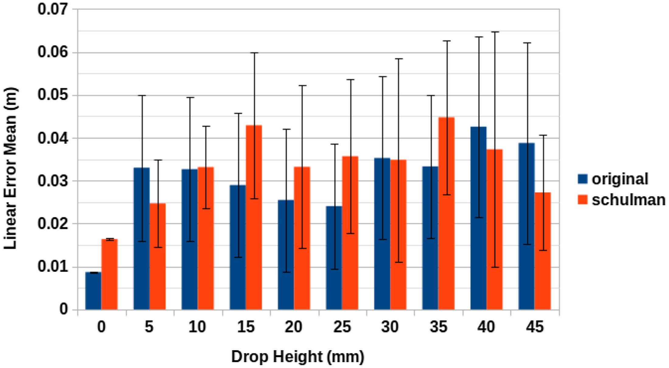
Figure 8 does not identify either of the two tracking methods as markedly better than the other. Out of the cases involving movement, drop heights of 10, 15, 20, 25 and $35\,\mathrm{mm}$
have the proposed method of this paper providing lower mean positional error values, mean the same is true for drop heights 5, 30, 40 and
$35\,\mathrm{mm}$
have the proposed method of this paper providing lower mean positional error values, mean the same is true for drop heights 5, 30, 40 and $45\,\mathrm{mm}$
for the Schulman et al. approach. Additionally, in all cases except the cases involving no drop, there is a large amount in variation in the linear error.
$45\,\mathrm{mm}$
for the Schulman et al. approach. Additionally, in all cases except the cases involving no drop, there is a large amount in variation in the linear error.
It would appear that the limiting factor in both cases is a combination of depth camera pointcloud resolution, accuracy and a lack of processing power to cope with larger pointclouds at a high rate of FPS. This explanation is reinforced by the results of Case Study 1, which demonstrated the bottleneck imposed on the accuracy of both methods by depth camera resolution and processing times. In this instance, these factors impeded the accuracy of each method to such a degree as to provide similar results for both approaches. Nonetheless, the accuracy of the results is similar to the accuracy demonstrated by Schulman et al. for a single RGBD camera. In their case, the tracking difficulty presented by the rope was due to occlusion by both the rope itself and the robot’s arms used for manipulation. In our case, we deliberately avoid such occlusion; however, the difficulty is instead derived from the speed and size of the swinging pipe.
Real-world tracking accuracy results: A comprehensive comparison between two tracking methods.
6.5. Discussion
Through the experiments detailed in the previous section, we have demonstrated that the proposed method has capability to track an LDO in simulation with a mean linear error of $0.970\,\mathrm{cm}$
, all the while with parts of the cable moving at speeds in excess of
$0.970\,\mathrm{cm}$
, all the while with parts of the cable moving at speeds in excess of $0.2\,\mathrm{m/s}$
. Furthermore, it has been demonstrated that by increasing the resolution and FPS of the depth camera, while reducing the computational load of the simulation we can reduce the mean linear error to
$0.2\,\mathrm{m/s}$
. Furthermore, it has been demonstrated that by increasing the resolution and FPS of the depth camera, while reducing the computational load of the simulation we can reduce the mean linear error to $0.702\,\mathrm{cm}$
while increasing the speed of various parts of the cable to be in excess of
$0.702\,\mathrm{cm}$
while increasing the speed of various parts of the cable to be in excess of $1\,\mathrm{m/s}$
. It is also worth noting that while several other works [Reference Schulman, Lee, Ho and Abbeel6,Reference Tang, Fan, Lin and Tomizuka23] use a detailed simulated model as part of their method, we use a simulation here purely for experimental purposes and our model as it stands requires little a priori information of the object to be tracked before it can be used.
$1\,\mathrm{m/s}$
. It is also worth noting that while several other works [Reference Schulman, Lee, Ho and Abbeel6,Reference Tang, Fan, Lin and Tomizuka23] use a detailed simulated model as part of their method, we use a simulation here purely for experimental purposes and our model as it stands requires little a priori information of the object to be tracked before it can be used.
These results were subsequently backed up by the results of the kinematic control system integration experiment. Here, the cases which were ran at 10% of real time with a higher resolution/FPS depth camera out performed the proposed approach by itself in terms of positional accuracy. The angular error was comparatively worse; however, even the worst-case mean equates to less than $15^\circ$
in angular error and this was for a case involving extremely high rates of angular change for the segments of the simulated LDO. The real-time cases had noticeably worse linear error; however, given the low error rates of the 10% of real-time and high-resolution/FPS cases, it is clear that the bottleneck on linear/angular error is processing time.
$15^\circ$
in angular error and this was for a case involving extremely high rates of angular change for the segments of the simulated LDO. The real-time cases had noticeably worse linear error; however, given the low error rates of the 10% of real-time and high-resolution/FPS cases, it is clear that the bottleneck on linear/angular error is processing time.
In addition, in the real-world experiment, we demonstrated an ability to track for a mean linear error of $3.03\,\mathrm{cm}$
across a variety of drop heights. Additionally, we found that the approach of Schulman et al. also provided a mean linear error of
$3.03\,\mathrm{cm}$
across a variety of drop heights. Additionally, we found that the approach of Schulman et al. also provided a mean linear error of $3.30\,\mathrm{cm}$
. Given the similarity in error values, the degradation in accuracy can likely be attributed to sensory and processing hardware imposing a bottleneck on the potential accuracy of either approach. This is reinforced by the results of the kinematic control system integration experiment.
$3.30\,\mathrm{cm}$
. Given the similarity in error values, the degradation in accuracy can likely be attributed to sensory and processing hardware imposing a bottleneck on the potential accuracy of either approach. This is reinforced by the results of the kinematic control system integration experiment.
Therefore, it is clear that the primary next step that should be taken is to both improve the speed with with computations can be carried out, both by running on more suitable hardware and utilising parallelism. Furthermore, future experimentation should be carried out with a real-time operating system to minimise variability in data processing times.
Finally, as discussed in Section 2, a feature of other contemporary methods which we have yet to explore is the ability to account for obscured parts of an object and maintain the structural integrity of the object throughout physical interactions. Currently, our model does not attempt to handle obscured parts of an object; furthermore, it does not consider the dynamics of the object. Facilitating some form of persistence here would expand the applications of this technique but allowing for greater levels of visual obstruction. Additionally, using this to enforce a level of temporal consistency may help to avoid erratic tracking output. The implementation of such persistence and the reduction of reliance on a priori knowledge of the object are suggested as strong avenues for future work.
7. Conclusion
In this work, an efficient novel method to tracking LDOs has been proposed. This involves repeatedly slicing a captured pointcloud of the object in question before constructing a mesh from nodes derived from the centroids of the sliced pointclouds. From here, a spline can be defined from the aforementioned nodes. This approach has been tested in both simulation and the real world. In simulation experiments, the proposed approach shows promise for tracking fast-moving LDOs accurately. Real-time tracking in simulation yielded a maximum case linear error of $1.21 \pm 0.825\,\mathrm{cm}$
, while tracking a
$1.21 \pm 0.825\,\mathrm{cm}$
, while tracking a $1.5$
-cm diameter LDO. Integration with a kinematic control system and analysis of the resultant worst-case error during a tracking task execution yield a maximum case error of
$1.5$
-cm diameter LDO. Integration with a kinematic control system and analysis of the resultant worst-case error during a tracking task execution yield a maximum case error of $2.58 \pm 3.18\,\mathrm{cm}$
. Meanwhile, in real-world experiments, we have demonstrated that the proposed method can compete with contemporary deformable object tracking methods.
$2.58 \pm 3.18\,\mathrm{cm}$
. Meanwhile, in real-world experiments, we have demonstrated that the proposed method can compete with contemporary deformable object tracking methods.
Acknowledgements
The authors would like to thank Dr Christopher Bibb for his technical support in installing the OptiTrack cameras.
Funding
This research was conducted as part of the project called “Reuse and Recycling of Lithium-Ion Batteries” (RELIB). This work was supported by the Faraday Institution [grant number FIRG005].
Data Availability Statement
The data that support the findings of this study are openly available in Figshare (https://figshare.com/s/9c24dda2aa383d38af1a) with doi (10.6084/m9.figshare.12084996) [Reference Rastegarpanah31].
Supplementary Material
To view supplementary material for this article, please visit https://doi.org/10.1017/S0263574721001065.


 Open access

