


1 Introduction
A wave packet with a vortex structure in the spatiotemporal dimension is called a spatiotemporal optical vortex (STOV)[ Reference Jhajj, Larkin, Rosenthal, Zahedpour, Wahlstrand and Milchberg1, Reference Dror and Malomed2], and has been a popular research subject in recent years. In view of its particular characteristic containing transverse orbital angular momentum (TOAM)[ Reference Allen, Beijersbergen, Spreeuw and Woerdman3], the STOV has significant potential applications in high-energy physics[ Reference Zhang, Ji and Shen4], high-speed information transmission[ Reference Huang, Li, Li, Zhang, Lu, Dorfman, Liu and Yao5] and quantum communication. There have been extensive researches on the STOV, such as its propagation characteristics[ Reference Huang, Wang, Shen, Liu and Li6– Reference Hancock, Zahedpour, Goffin and Milchberg9], frequency transforms[ Reference Hancock, Zahedpour and Milchberg10– Reference Chen, Kuai, Chen, Yu and Zhan13], manipulations[ Reference Chen, Kuai, Chen, Yu and Zhan13– Reference Zang, Wei, Kim and Chong15] and characterizations[ Reference Hancock, Zahedpour and Milchberg16, Reference Chen, Zhou, Li, Liu, Ciappina and Lu17]. When STOV lasers are extended to the relativistic field, they will present novel phenomena and great application value in the relativistic laser–matter interaction field simultaneously[ Reference Shi, Zhang, Arefiev and Shen18– Reference Guo, Zhang, Zhang and Shen20]. Recently, applications of STOVs with relativistic intensity (usually >1018 W/cm2) were proposed[ Reference Piccardo, Cernaianu, Palastro, Arefiev, Thaury, Vieira, Froula and Malka21] and the relevant simulations were conducted, including the generation of an isolated attosecond electron sheet[ Reference Sun, Wang, Dong, He, Shi, Lv, Zhan, Leng, Zhuang and Li22], γ photons and pairs[ Reference Zhang, Zhang and Xie23] and a γ-ray pulse[ Reference Sun, Xie, Wang, Weber, Zhang, Leng, Li and Xu24], generation of an intense spatiotemporal high harmonic[ Reference Zhang, Ji and Shen4, Reference Chen, Hu, Zhang and Yuan25– Reference Jiang, Zhang, Wu and Liu27], electron acceleration and generation of attosecond hard X-rays[ Reference Ju, Wu, Yu, Huang, Zhang, Wu, Zhou and Ruan28], governing interference photoelectron momentum distributions[ Reference Liu, Zhang, Zhang, Shi and Yao29].
For instance, in the direct laser-driven particle acceleration field, the STOV laser has unique advantages. Traditional ultra-intense Gaussian lasers accelerate high-energy particle beams with large divergence angles due to their unique Gaussian distribution of pondermotive force[ Reference Tian, Liu, Wang, Wang, Deng, Xia, Li, Cao, Lu, Zhang, Xu, Leng, Li and Xu30, Reference Thévenet, Leblanc, Kahaly, Vincenti, Vernier, Quéré and Faure31]. This is not conducive to many applications, such as fast ignition[ Reference Li, Yan, Ren, Wang, Tonge and Mori32, Reference Zhang, Cai, Zhou, Dai, Shan, Xu, Chen, Ge, Tang, Zhang, Wei, Liu, Gu, Du, Bi, Wu, Li, Lu, Zhang, Zhang, He, Yu, Yang, Wang, Zhang, Cui, Yang, Wu, Qi, Cao, Li, Liu, Yang, Ren, Tian, Yuan, Zheng, Cao, Zhou, Zou, Gu, Du, Ding, Zhang, Zhu, Zhang and He33], the generation of high-brightness radiation sources[ Reference Yu, Liu, Zhao, Zhu, Lu, Cao, Zhang, Shao and Sheng34, Reference Zhang, Zhao, Hu, Li, Lu, Cao, Zou, Sheng, Pegoraro, McKenna, Shao and Yu35] and the excitation of high-energy nuclear physics[ Reference Ledingham, McKenna and Singhal36]. The emergence of ultra-intense vortex lasers with spatial helical wavefront structures, such as Laguerre–Gaussian (LG) lasers[ Reference Wang, Jiang, Dong, Lu, Li, Xu, Sun, Yu, Guo, Liang, Leng, Li and Xu37], confines and modulates spatially high-energy particles, achieving the acceleration of collimated particle beams due to the spatial hollow pondermotive force distribution[ Reference Wang, Jiang, Shen, Yuan, Gan, Zhang, Zhai and Xu38, Reference Wang, Sun, Sun, Lv, Glize, Shi, Xu, Zhang, Wu, Hu, Qian, Zhu, Liang, Leng, Li and Xu39]. Meanwhile, the longitudinal orbital angular momentum (OAM) of the LG laser can be transferred to the accelerated particle source and generated radiation source[ Reference Wang, Shen, Zhang, Zhang, Shi and Xu40]. Nevertheless, such an LG laser can achieve spatial modulation of the particle beam, but lacks temporal modulation, which limits the application and development of high-energy particle beams and radiation sources in ultrafast fields[ Reference Drescher, Kienberger, Uiberacker, Yakovlev, Scrinzi, Westerwalbesloh, Heinzmann and Krausz41]. The emergence of the ultra-intense STOV laser is expected to solve this problem, because of its hollow pondermotive force distribution in spatiotemporal dimensions. This is expected to extend the spatial modulation by the LG laser to the spatiotemporal modulation by the STOV laser[ Reference Sun, Wang, Dong, He, Shi, Lv, Zhan, Leng, Zhuang and Li42], to generate collimated ultrafast particle pulses. At the same time, the transverse OAM carried by the STOV laser will be transferred to the particle beam, expanding a new degree of freedom on the basis of the LG laser.
However, schemes generating STOVs with single-pulse energy of more than 1 mJ are infrequently seen, let alone the ultra-intense STOV with tens of joules of pulse energy. Now, there are two types of universal methods to generate STOVs. One is based on the 4f system or analogous system[ Reference Huang, Wang, Shen and Liu7, Reference Chong, Wan, Chen and Zhan43], sculpturing the spatiotemporal structure in the Fourier plane by a phase mask. This method is only suitable for a small caliber (usually <1 mm) and narrow spectral width (usually <5 nm) for the limited propagation distance and limited caliber of the cylindrical lens used to align the beam. At the same time, the damage threshold of the grating is the dominant factor limiting the energy of STOVs below the mJ level. So, considering the restriction of the spot size, spectral width and grating damage threshold, the traditional 4f system is not suitable for ultra-intense STOV generation. Another method is to directly generate STOVs through micro-structured materials[ Reference Huang, Zhang, Zhu and Ruan44– Reference Zhang, Cui, Zeng, Chen, Liu, Wang, Wang, Zhang, Wang, Wu and Chan48]. The intensity of the STOV generated by this kind of method is also limited by the damage threshold of the materials. Meanwhile, the low efficiency and high cost hinder the practical application of this delicate component. In conclusion, neither the 4f system nor micro-structured materials have the ability to produce ultra-intense STOVs. Therefore, it is necessary to put forward a universal and robust method to generate STOVs with several or even tens of joules.
In this paper, a novel method for modifying a grating compressor to generate ultra-intense STOVs is proposed by utilizing the principle of the pulse shaper[ Reference Heritage, Weiner and Thurston49]. The simulation results demonstrated that the modified grating compressor system is able to generate STOVs with tens of joules of energy, and 1021 W/cm2 peak intensity can be achieved in the focus. At an existing ultra-high-peak-power facility, the Shanghai Ultra-intense Laser Facility (SULF), we can obtain STOVs with more than 1020 W/cm2 peak intensity, just by modifying the structure of the grating-based compressor in the chirped pulse amplification (CPA)[ Reference Strickland and Mourou50]. Finally, a proof-of-principle experiment was conducted to verify this method, with the corresponding simulation results proving its practicability.
2 Method
Since the damage threshold of the grating is the main factor limiting the peak intensity of STOVs, it is natural to expand the spot size of the input beam to increase the pulse energy. In addition, broadening the spectra is an excellent way of obtaining a shorter duration and more intense focal intensity. So, directly adopting a femtosecond light source with a broadband spectrum is beneficial. Nevertheless, the key process of generating STOVs is the introduction of spatial dispersion. During this process, broadening the spectra with adequate spatial dispersion will expand the diameter in the X direction, the result of which is that large-sized cylindric lens with a diameter of more than 1 m is needed. More importantly, wavefront distortion caused by the cylindric lens is unavoidable. Compared to the cylindric lens, the grating pair has the same dispersion and alignment functions but with a tiny wavefront distortion. In addition, so far, the production of large-scale gratings is feasible.
Furthermore, it is worth noting that the grating pair can introduce not only spatial dispersion but also negative temporal dispersion. To compensate for spatial dispersion, a symmetric grating pair should be set after the phase mask to compensate for the equal spatial dispersion. In addition, considering the negative temporal dispersion caused by the grating pairs, the input pulse should be positively pre-chirped.
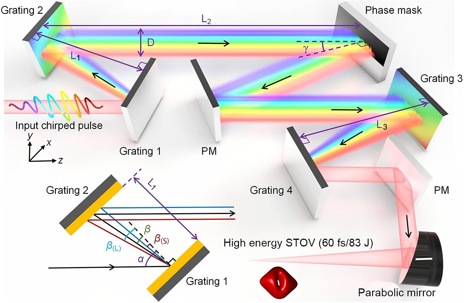
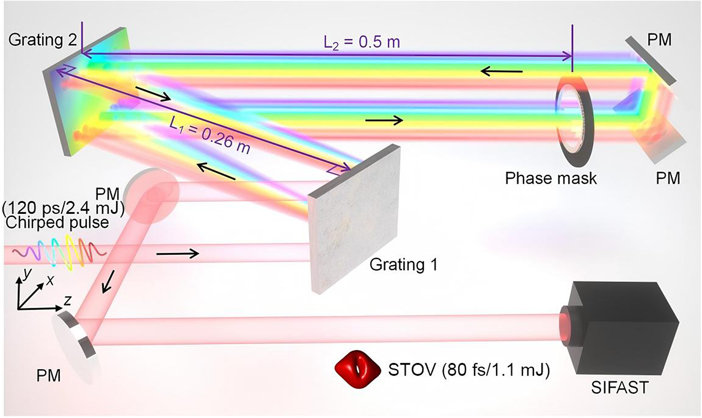
Fortunately, for ultra-high-peak-power lasers, the stretcher and compressor in CPA can induce pre-chirp to the input pulse and generate STOVs easily. The generation system is illustrated in Figure 1. Firstly, the first grating pair introduces appropriate spatial dispersion in the positively pre-chirped pulse. Then the phase mask is placed between the two grating pairs to modulate the spatial and spectral phase of the laser. Finally, after the spatially dispersive compensation by the second grating pair, the STOV can be generated in the near- or far-field of the four-grating compressor STOV generation system (FGC-SGS), depending on the function in the phase mask. Next, we will analyze the specific parameters of the FGC-SGS, based on the Fourier diffraction theory and dispersive theory.
Modified grating compressor for the generation of ultra-intense STOVs with 60 fs pulse duration and 83 J pulse energy. PM, plane mirror; L
1 and L
3, perpendicular distances of the first and second grating pair, respectively; D, diameter in the X direction after Grating 2; L
2, distance between Grating 2 and the phase mask; $\gamma$
, incident angle of the phase mask, which depends on the actual experimental condition.
$\gamma$
, incident angle of the phase mask, which depends on the actual experimental condition.

3 Numerical simulation
Based on the above analysis, the spatial dispersion and beam alignment are achieved by using a grating pair. In addition, the input pulse before Grating 1 should be positively chirped.
The input pulse can be represented as follows:
 $$\begin{align}{E}_1\left(x,y,t\right)&=\sqrt{I_0}\exp \left[-{\left({x}^2+{y}^2\;\right)}^{10}/{a}^{20}\right]\nonumber\\&\quad\cdot \exp \left[-\left(1+ iC\right){t}^2/2{T}_0^2\right].\end{align}$$
In Equation (1), ${I}_0$
is the peak intensity,
${I}_0$
is the peak intensity, $a$
is the radius of spot,
$a$
is the radius of spot, $C$
is the chirp amount and
$C$
is the chirp amount and ${T}_0$
is the temporal duration.
${T}_0$
is the temporal duration.
After the grating pair, the temporal and spatial dispersion introduced by the pair can be expressed with the following equation:
 $$\begin{align}\phi \left(\omega, {f}_x\right)={\phi}_0+{\phi}^{\prime}\Omega +\frac{\phi^{\prime \prime }}{2}{\Omega}^2+{\tau}_x\frac{f_x}{k_0}\Omega.\end{align}$$
Here, $\phi \left(\omega, {f}_x\right)$
is the relative phase delay of different temporal frequencies
$\phi \left(\omega, {f}_x\right)$
is the relative phase delay of different temporal frequencies $\omega$
and different transverse spatial frequencies
$\omega$
and different transverse spatial frequencies ${f}_x$
,
${f}_x$
, ${\phi}^{\prime }$
and
${\phi}^{\prime }$
and ${\phi}^{\prime \prime }$
are the group delay and group delay dispersion (GDD)[
Reference Martinez51], respectively, and
${\phi}^{\prime \prime }$
are the group delay and group delay dispersion (GDD)[
Reference Martinez51], respectively, and $\Omega =\omega -{\omega}_0$
is the frequency difference between each frequency component and the central frequency
$\Omega =\omega -{\omega}_0$
is the frequency difference between each frequency component and the central frequency ${\omega}_0$
. The last term on the right-hand side is the delays of spatial frequency by time, where
${\omega}_0$
. The last term on the right-hand side is the delays of spatial frequency by time, where ${\tau}_x$
is the delay coefficient[
Reference Khazanov52] and
${\tau}_x$
is the delay coefficient[
Reference Khazanov52] and ${k}_0=\frac{2\pi }{\lambda_0}$
is the wave number in vacuum.
${k}_0=\frac{2\pi }{\lambda_0}$
is the wave number in vacuum.
Therefore, the optical field after the grating pair is represented as follows:
Note that ${E}_1\left({f}_x,{f}_y,\omega \right)=\mathrm{FFT}_2\left[{E}_1\left(x,y,\omega \right)\right]$
is the two-dimensional Fourier transform in the spatial domain for
${E}_1\left({f}_x,{f}_y,\omega \right)=\mathrm{FFT}_2\left[{E}_1\left(x,y,\omega \right)\right]$
is the two-dimensional Fourier transform in the spatial domain for ${E}_1\left(x,y,\omega \right)$
, and
${E}_1\left(x,y,\omega \right)$
, and ${E}_1\left(x,y,\omega \right)= \mathrm{FFT}\left[{E}_1\left(x,y,t\right)\right]$
is the Fourier transform in the temporal domain. The optical field after the free propagation of distance L
2 can be expressed as follows:
${E}_1\left(x,y,\omega \right)= \mathrm{FFT}\left[{E}_1\left(x,y,t\right)\right]$
is the Fourier transform in the temporal domain. The optical field after the free propagation of distance L
2 can be expressed as follows:
where $H\left({f}_x,{f}_y,\omega \right)=\exp \left[ ikL- i\pi {\lambda}_0L\left({f}_x^2+{f}_y^2\right)\right]$
is the free propagation function.
$H\left({f}_x,{f}_y,\omega \right)=\exp \left[ ikL- i\pi {\lambda}_0L\left({f}_x^2+{f}_y^2\right)\right]$
is the free propagation function.
Then the optical field after the phase mask is as follows:
where $P\left(x,y\right)$
is the function of the phase mask.
$P\left(x,y\right)$
is the function of the phase mask.
The following processes are the same as the previous steps (Equations (4) and (3)) but with the reverse order. In addition, the optical field after the Grating 4 is ${E}_5\left(x,y,t\right)$
. The function of a parabolic mirror can be approximately written as
${E}_5\left(x,y,t\right)$
. The function of a parabolic mirror can be approximately written as ${F}_{\mathrm{PM}}=\exp \left[-\frac{i{k}_0\left({x}^2+{y}^2\right)}{2f}\right]$
, where
${F}_{\mathrm{PM}}=\exp \left[-\frac{i{k}_0\left({x}^2+{y}^2\right)}{2f}\right]$
, where $f$
is the focal length. Finally, the STOV is formed at the focus of a parabolic mirror.
$f$
is the focal length. Finally, the STOV is formed at the focus of a parabolic mirror.
4 Results
4.1 Ultra-intense STOV generation
For a 10th-order super-Gaussian input pulse with radius $a$
= 115 mm, 800 nm central wavelength, 30 fs duration (note that if not specifically stated, the pulse duration is the full width at half maximum, FWHM) and 1480 line/mm gold-plated gratings, employing a spiral phase mask, the STOV with topological charge
$a$
= 115 mm, 800 nm central wavelength, 30 fs duration (note that if not specifically stated, the pulse duration is the full width at half maximum, FWHM) and 1480 line/mm gold-plated gratings, employing a spiral phase mask, the STOV with topological charge $l$
= 1 is generated in the focal plane with
$l$
= 1 is generated in the focal plane with $f$
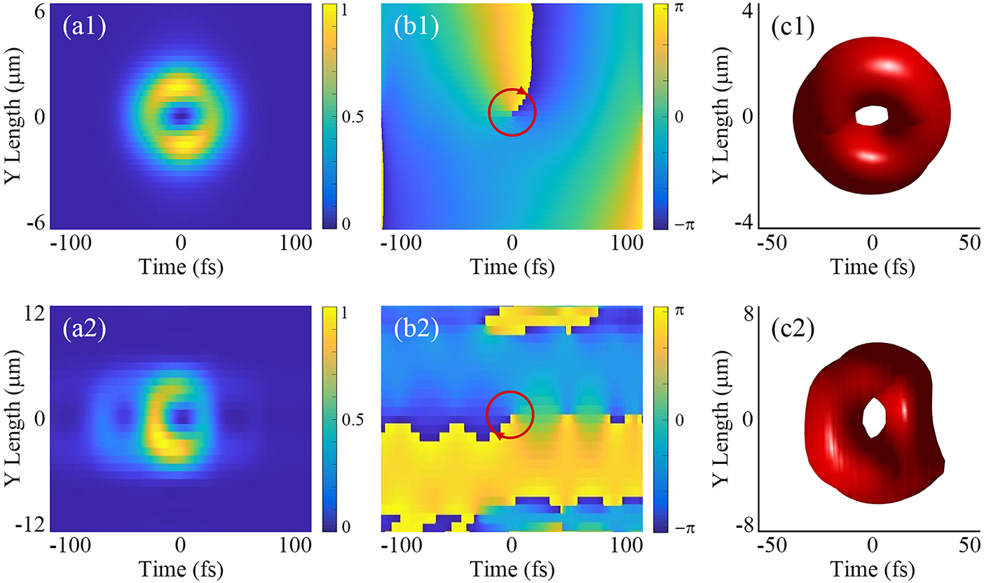
= 0.5 m, as shown in Figure 2. The intensity distribution presents a ringlike shape, with a phase singularity embedded in the Y–T plane, which is accorded with the description of the STOV. A doughnut form iso-surface is shown in Figure 2(c1), demonstrating that the direction of its intrinsic OAM is along the X-axis, but not the T-axis. More importantly, taking the damage threshold of the gold grating as 0.2 J/cm2, the maximal output energy can be up to 83.1 J in theory. Considering the spatial radius of the STOV in the focusing plane is about 3 μm and the pulse duration is about 60 fs, it is easy to obtain the theoretical maximal intensity of 5 × 10²¹ W/cm2. Considering that each grating’s diffraction efficiency is 87% in the compressor, the total energy conversion efficiency is about 58%.
$f$
= 0.5 m, as shown in Figure 2. The intensity distribution presents a ringlike shape, with a phase singularity embedded in the Y–T plane, which is accorded with the description of the STOV. A doughnut form iso-surface is shown in Figure 2(c1), demonstrating that the direction of its intrinsic OAM is along the X-axis, but not the T-axis. More importantly, taking the damage threshold of the gold grating as 0.2 J/cm2, the maximal output energy can be up to 83.1 J in theory. Considering the spatial radius of the STOV in the focusing plane is about 3 μm and the pulse duration is about 60 fs, it is easy to obtain the theoretical maximal intensity of 5 × 10²¹ W/cm2. Considering that each grating’s diffraction efficiency is 87% in the compressor, the total energy conversion efficiency is about 58%.
Simulation results of the generation of ideal (a1)–(c1) and practical (a2)–(c2) ultra-intense STOVs in the focal plane. Here, (a1) and (a2) are the intensity distributions of the STOV in the Y–T plane at the X = 0 position, (b1) and (b2) are the corresponding phase distributions and (c1) and (c2) are the iso-surfaces at one-third of the maximum intensity.

Although the STOV generated with the four-grating compressor is convenient for most high-power laser systems, the specific optical path and component size should be taken into full consideration. To maintain enough spatial dispersion, the perpendicular distance of the grating pair should be at least 6 m. The result of this is that Gratings 2 and 3 have to be wider to adapt to the dispersed spot. It is easy to calculate the diameter of the output pulse from Grating 2 with Equation (6):
In this formula, ${\beta}_{(\mathrm{L})}$
and
${\beta}_{(\mathrm{L})}$
and ${\beta}_{(\mathrm{S})}$
are the diffraction angles of the longest and shortest wave components, respectively, as shown in the embedded picture in Figure 1. In addition, the real spot width on the grating surface is
${\beta}_{(\mathrm{S})}$
are the diffraction angles of the longest and shortest wave components, respectively, as shown in the embedded picture in Figure 1. In addition, the real spot width on the grating surface is $D/\cos \left(\alpha \right)$
. Assuming the incident angle
$D/\cos \left(\alpha \right)$
. Assuming the incident angle $\alpha$
= 49° and the grating period d = 1/1480 mm, the corresponding grating width should be at least 1.32 m. Such a large-scale grating is under-producing[
Reference Han, Li, Jin, Cao, Kong and Shao53] and will be applied in a future ultra-high-peak-power laser facility.
$\alpha$
= 49° and the grating period d = 1/1480 mm, the corresponding grating width should be at least 1.32 m. Such a large-scale grating is under-producing[
Reference Han, Li, Jin, Cao, Kong and Shao53] and will be applied in a future ultra-high-peak-power laser facility.
On the other hand, the grating pairs introduced not only spatial dispersion but also temporal GDD, which is related to the grating pair perpendicular distance[ Reference Martinez51]. Therefore, it is necessary to calculate the duration of the positively pre-chirped pulse before the grating pair. If the generated STOV is a Fourier transform limit (FTL) pulse, the input pulse duration can be calculated with the following formula[ Reference Marcuse54]:

For L
1 = L
3 = 6 m, ${T}_{\mathrm{input}}$
= 3.00 ns.
${T}_{\mathrm{input}}$
= 3.00 ns.
Taking a real 1 PW facility, the SULF, as an example, the maximal grating size is 360 mm (H) × 565 mm (W), which limits the input beam size and perpendicular distance L 1. If the proper beam diameter is set to 100 mm, the maximal L 1 should be 2.6 m to make full use of the area of Grating 2. Substituting the practical laser parameters[ Reference Zhang, Wu, Hu, Yang, Gui, Ji, Liu, Wang, Liu, Lu, Xu, Leng, Li and Xu55] in the simulation model, we can obtain the intensity and phase distribution of the generated ultra-intense STOV, as shown in Figures 2(a2) and 2(b2). Besides the main spatiotemporal ring structure at T = 0, there are several interconnected rings with low energy distributed on both sides, because of the temporal sidelobes in the input pulse. In addition, the iso-surface at focus is displayed in Figure 2(c2), which is slightly different from that shown in Figure 2(c1). Although the nonuniformity of the intensity distribution in the spatial domain and the non-ideal spectrum distorted the STOV shape, it still maintained an intact vortex state. Besides, according to the above results, we can calculate the corresponding peak intensity of the STOV, which is approximately 0.14 × 10²¹ W/cm2. This intensity is much greater than the relativistic intensity of 1018 W/cm2 and is suitable for application in actual experiments. In addition, in the temporal domain, the practical input pulse should be stretched to 1.29 ns to match the perpendicular distances L 1 and L 3.
4.2 Effect of the phase mask function
It is well-known that the function of the phase mask directly decides the pulse structure in the focus. In the ultra-intense STOV generation process, the spot before the phase mask is expended more in the X direction. Therefore, it is necessary to adjust the distribution ratio of the vortex phase in the X and Y directions to construct a complete STOV shape. For any point $\left(x,y\right)$
on the phase mask, the phase that should be introduced at that position is decided by phase angle
$\left(x,y\right)$
on the phase mask, the phase that should be introduced at that position is decided by phase angle $\theta$
. The phase angle
$\theta$
. The phase angle
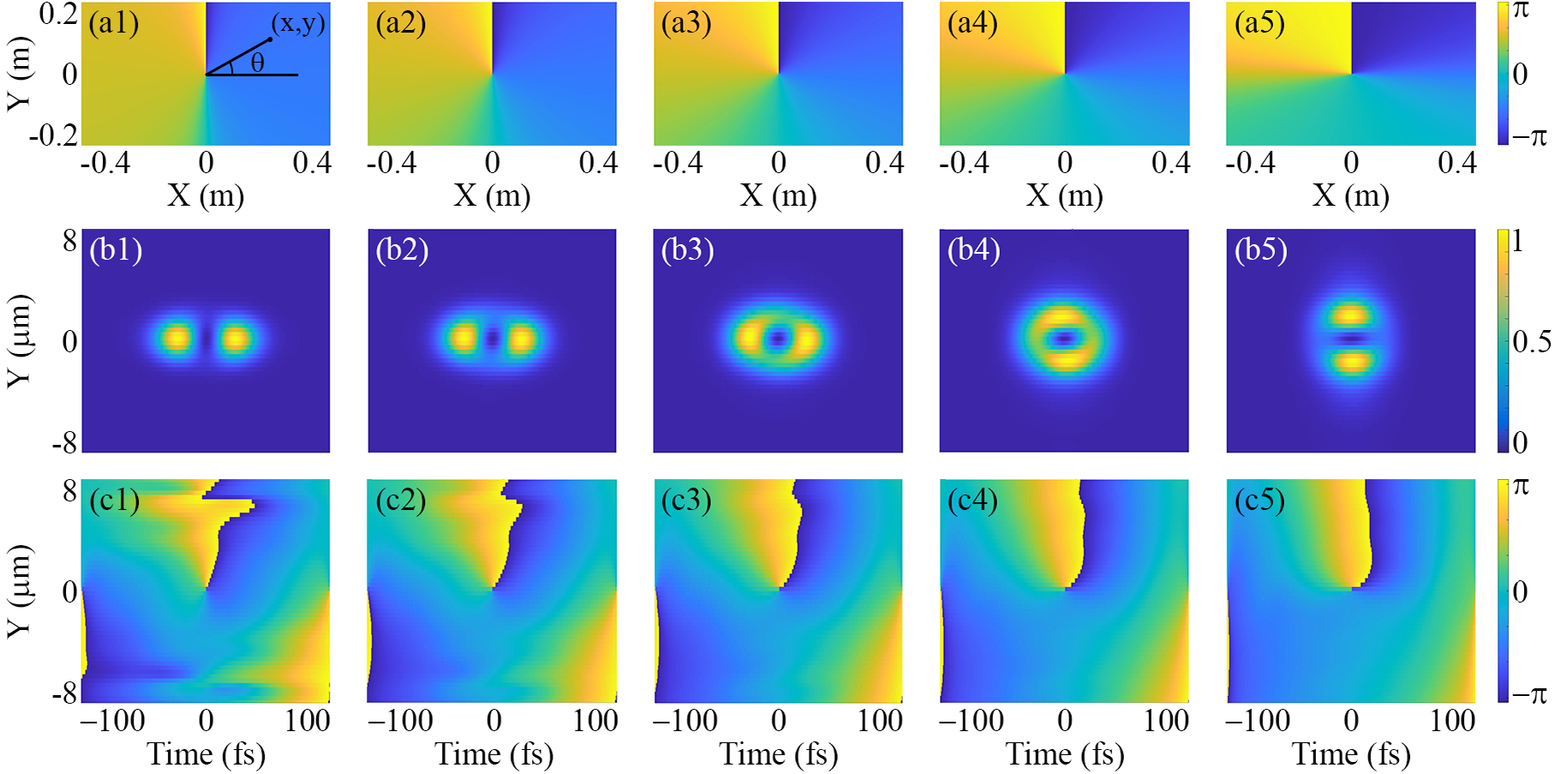
 $\theta =\arctan \left(\sigma \cdot \frac{y}{x}\right)$
is marked in Figure 3(a1). Therefore, the phase mask function can be written as follows:
$\theta =\arctan \left(\sigma \cdot \frac{y}{x}\right)$
is marked in Figure 3(a1). Therefore, the phase mask function can be written as follows:
(a1)–(a5) The different functions of the phase mask, with $\sigma$
= 0.2, 0.5, 1, 2, 5 in sequence. Here, (b1)–(b5) and (c1)–(c5) are the corresponding intensity and phase distributions in the focus, respectively.
$\sigma$
= 0.2, 0.5, 1, 2, 5 in sequence. Here, (b1)–(b5) and (c1)–(c5) are the corresponding intensity and phase distributions in the focus, respectively.

where $\sigma$
is the distribution ratio coefficient, used to adjust the distribution ratio in the X and Y directions, and
$\sigma$
is the distribution ratio coefficient, used to adjust the distribution ratio in the X and Y directions, and $l$
is the topological charge of the phase mask, which is equal to 1 in this section. Similar to the previous simulation, the STOV intensity and phase distributions in the focus with
$l$
is the topological charge of the phase mask, which is equal to 1 in this section. Similar to the previous simulation, the STOV intensity and phase distributions in the focus with $\sigma$
from 0.2 to 5 are illustrated in Figure 3. With the increase of
$\sigma$
from 0.2 to 5 are illustrated in Figure 3. With the increase of $\sigma$
, the phase distribution range in the X direction is narrowed gradually, as shown in Figures 3(a1)–3(a5), resulting in a regular evolution from a transverse double-lobe structure to a circinate structure and finally to a longitudinal double-lobe structure, as shown in Figures 3(b1)–3(b5). In addition, the corresponding phase distributions are displayed in Figures 3(c1)–3(c5). Obviously, when
$\sigma$
, the phase distribution range in the X direction is narrowed gradually, as shown in Figures 3(a1)–3(a5), resulting in a regular evolution from a transverse double-lobe structure to a circinate structure and finally to a longitudinal double-lobe structure, as shown in Figures 3(b1)–3(b5). In addition, the corresponding phase distributions are displayed in Figures 3(c1)–3(c5). Obviously, when $\sigma$
= 2, we can obtain the most appropriate spatiotemporal spiral structure. This is because for a large aperture spot, the spatially dispersed pulse should be uniformly modulated by the spiral phase gradient. This means that the function in the phase mask should opportunely match the spot size on the mask. For a practical input pulse, the function is affected by the spot size, the dispersive ability of grating and the distance L
2, which can be strictly determined by simulation.
$\sigma$
= 2, we can obtain the most appropriate spatiotemporal spiral structure. This is because for a large aperture spot, the spatially dispersed pulse should be uniformly modulated by the spiral phase gradient. This means that the function in the phase mask should opportunely match the spot size on the mask. For a practical input pulse, the function is affected by the spot size, the dispersive ability of grating and the distance L
2, which can be strictly determined by simulation.
4.3 High-order ultra-intense STOVs
In the above text, we talked about the generation of an ultra-intense STOV with topological charge $l$
= 1. In this part, high-order ultra-intense STOVs with
$l$
= 1. In this part, high-order ultra-intense STOVs with $l$
= 2, 3, 4 were produced in simulation, as shown in Figure 4. All the STOVs were generated with
$l$
= 2, 3, 4 were produced in simulation, as shown in Figure 4. All the STOVs were generated with $\sigma$
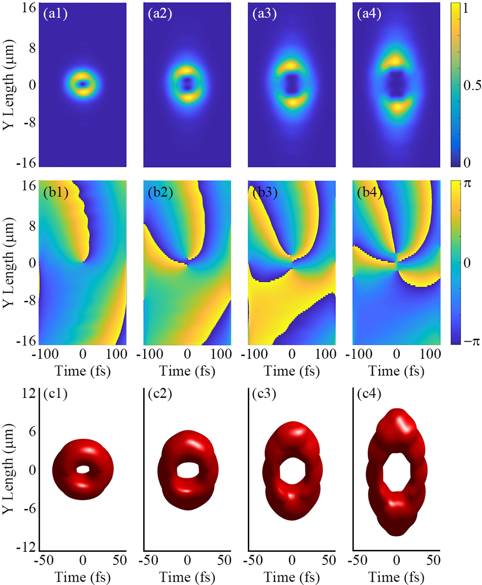
= 2. In the first line, it is easy to observe that the number of holes in the vortexes increased with the increasing topological charge. Simultaneously, the number of phase vortexes also increased in sequence, as shown in the second line. Due to the impact of phase singularities, the hole of the iso-surface enlarged with the increase of topological charge, but the entire wave packet still maintained a complete doughnut shape, as shown in the third line.
$\sigma$
= 2. In the first line, it is easy to observe that the number of holes in the vortexes increased with the increasing topological charge. Simultaneously, the number of phase vortexes also increased in sequence, as shown in the second line. Due to the impact of phase singularities, the hole of the iso-surface enlarged with the increase of topological charge, but the entire wave packet still maintained a complete doughnut shape, as shown in the third line.
Simulation results of STOVs with topological charges $l$
= 1, 2, 3, 4, in turn. Here, (a1)–(a4) and (b1)–(b4) are the intensity and phase distributions in the focus, respectively, and (c1)–(c4) are the corresponding iso-surfaces at one-third of the maximum intensity (the multi-hole structure does not appear in (c2)–(c4) due to the large iso-surface value).
$l$
= 1, 2, 3, 4, in turn. Here, (a1)–(a4) and (b1)–(b4) are the intensity and phase distributions in the focus, respectively, and (c1)–(c4) are the corresponding iso-surfaces at one-third of the maximum intensity (the multi-hole structure does not appear in (c2)–(c4) due to the large iso-surface value).

Ultra-intense STOVs with topological charge $l$
> 1 provide a new variable in the research of strong-field physics, which can directly affect the TOAM of the generated radiation source and accelerated particle source. As the topological charge
$l$
> 1 provide a new variable in the research of strong-field physics, which can directly affect the TOAM of the generated radiation source and accelerated particle source. As the topological charge $l$
increases, higher-order charges (
$l$
increases, higher-order charges ( $l$
> 1) provide a larger phase difference and the associated longitudinal electric field within the singularity is inherently weaker than in the
$l$
> 1) provide a larger phase difference and the associated longitudinal electric field within the singularity is inherently weaker than in the $l$
= 1 case, potentially limiting the acceleration gradient. Furthermore, structural instability and spatial diffraction often cause higher-order singularities to degenerate into multiple
$l$
= 1 case, potentially limiting the acceleration gradient. Furthermore, structural instability and spatial diffraction often cause higher-order singularities to degenerate into multiple $l$
= 1 singularities during propagation; this splitting weakens the transverse focusing effect and leads to increased beam divergence. However, the significantly higher TOAM carried by these STOVs can be efficiently transferred to particles, offering a unique mechanism for generating high-TOAM particle beams for special applications in chiral light–matter interaction and vortex secondary radiation sources.
$l$
= 1 singularities during propagation; this splitting weakens the transverse focusing effect and leads to increased beam divergence. However, the significantly higher TOAM carried by these STOVs can be efficiently transferred to particles, offering a unique mechanism for generating high-TOAM particle beams for special applications in chiral light–matter interaction and vortex secondary radiation sources.
5 Experiment
To verify the practicality of this ultra-intense STOV generation scheme, a miniaturization device was constructed in the laboratory. The experimental schematic diagram is shown in Figure 5. A 1 kHz repetition Ti:sapphire CPA laser was used to produce the input pulse with 800-nm central wavelength, 120-ps pulse duration, 2.4 mJ energy and 6-mm spot diameter. The perpendicular distance L 1 between the grating pair is 0.26 m. The distance from the second grating to the phase mask L 2 equals 0.5 m. Similar to the STOV generating system in Figure 1, the STOVs were able to be produced in the far-field, or rather in the focus of a parabolic mirror with a spiral phase mask. Considering the measurement conditions, STOV pulses were generated in near-field by a 1-inch phase mask having 0-π phase distribution[ Reference Huang, Wang, Shen and Liu7]. For details about the simulation results of the STOVs obtained in the near-field in Figure 1 and in the far-field in Figure 5, please refer to the Supplementary Material. The phase function of the phase mask is as shown in the embedded picture in Figure 6(a1). The angle between the 0-π dividing line and X-axis is about 15°. With two plane mirrors, the pulses were reflected and backtracked to Grating 2 in a different horizontal plane. Finally, measurement of the generated STOV pulses was conducted with a home-made spectral interferometry with a fiber array for single-shot spatiotemporal characterization (SIFAST)[ Reference Xu, Shen, Chen, Liang, Wang, Liu and Li56]. The measurement results are illustrated in Figure 6.
Schematic diagram of the verification experiment. PM, plane mirror.

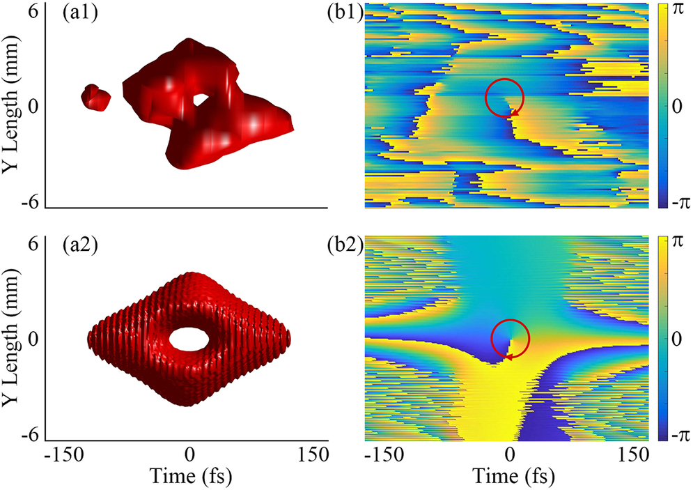
(a1), (b1) Measurement results of the iso-surface at 1/10 maximum intensity and phase distribution in the Y–T plane, respectively. The function of the phase mask is embedded in the left-hand part of (a1). (a2), (b2) The corresponding simulation results.

The measurement resolution of SIFAST is 0.4 fs in the temporal domain and 100 µm in the spatial domain. In addition, the measured temporal FWHM of the STOV is about 80 fs, which is close to the simulation result. In Figure 6(a1), the experimental result is basically the same as the simulation result in Figure 6(a2), despite the experimental result showing a little nonuniformity in intensity distribution, compared to the ideal iso-surface. This discrepancy is usually attributed to the uneven spectral distribution related to the original incident pulse, and phase distortion caused by the non-ideal grating pairs. These problems can be solved with high-quality large-scale grating pairs and a better light source in the high-peak-power laser facility. Also, the structure of singularity in Figure 6(a1) is clear in the Y–T plane, accorded with the position of the phase singularity in Figure 6(b1). For phase distribution, benefited from the high resolution of the SIFAST, the spiral phase was characterized distinctly, which is fundamentally identical to the simulation one. However, because the spiral phase of the STOV in the Y–T phase was very susceptible to the slight deformation of optical components, the phase distortion was unavoidable after several lenses in the measuring device. Also, the instability of the beam will affect the phase distribution for the measuring process, usually at the cost of tens of seconds.
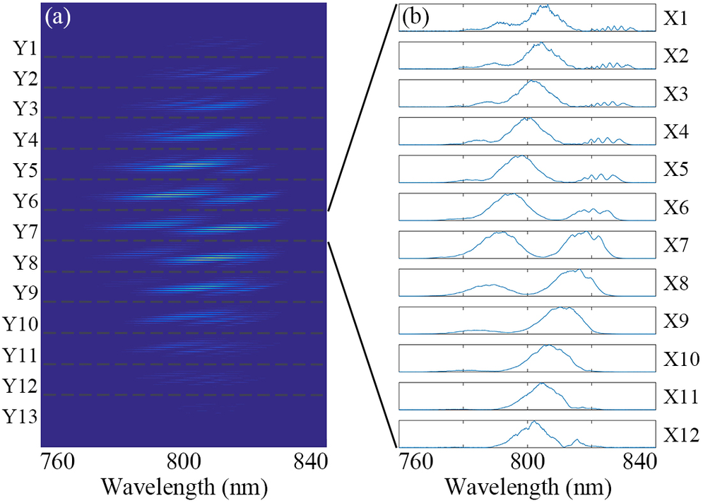
The three-dimensional (3D) spectral data of the pulses collected by SIFAST at intervals of 1.1 mm are shown in Figure 7. The spectra of the 13 × 12 points are plotted in Figure 7(a), where each group of the spectra between two dotted lines is the spectra of all the points in this row (rows Y1–Y13). In addition, the spectra of row Y7 are plotted in detail in Figure 7(b) (row Y7, subsets X1–X12). Due to the 0-π function of the phase mask, the boundary of the phase step separates the spectra in both the Y and X directions, as Figures 7(a) and 7(b) show. In particular, in row Y7, subset X7, the spectrum was divided into two lobes equally, without the spectral component of the central wavelength. It is precisely this two-part spectrum with a π phase difference that reconstitutes a wave packet without dispersion after the second grating pair, but a phase singularity was retained at the center. Therefore, from the directly measured spectral data, we can also infer that the characterization of the STOV is accurate and reliable.
(a) Three-dimensional spectral interferometry map measured by spatiotemporal spectrometer in SIFAST. (b) Spectra of subsets X1–X12, from line Y7.

The single-pulse energy of the generated STOV was 1.1 mJ, with about 46% conversion efficiency. The main loss in the generation system comes from the diffraction efficiency of the grating. So, the calculated diffraction efficiency of one grating is 82%, which is the same as the laboratory measurement result. Actually, the energy is constrained by the laser’s maximal output energy. In theory, it is possible to generate a STOV with 50 mJ energy using the device shown in Figure 5.
6 Conclusion
In this paper, we first analyzed the application background of the ultra-intense STOV and its significance in strong-field physics. Subsequently, we also introduced the potential methods for generating an ultra-intense STOV. Later, based on the ordinary 4f system, we proposed the FGC-SGS method for generating an ultra-intense STOV, which avoids the limitations of the grating damage threshold and the large-aperture cylindrical lens. It is the first time that an effective method has been provided for the generation of a STOV with tens of joules of energy. In Section 3, based on the Fourier diffraction formula and dispersive theory, we conducted a simulation of the physical process of this method and obtained the ultra-intense STOV at the focus. The results showed that for a super-Gaussian pulse with 800-nm central wavelength and 230-mm diameter, theoretically a STOV with 60-fs duration, 83-J energy and 5 × 10²¹ W/cm2 peak intensity can be obtained at the focal point. Furthermore, considering the parameters of a practical ultra-high-peak-power laser facility, the SULF, we obtained the information about the actual ultra-intense STOV that it could produce. Due to the limitations of the actual spot quality and pulse energy, the final peak intensity that could be achieved was approximately 0.14 × 10²¹ W/cm2. The influence of the phase mask function and the generation of a high-order ultra-intense STOV have also been thoroughly studied by simulations.
In Section 5, a verification experiment was conducted with a small-size FGC-SGS device. A STOV with about 1.1 mJ energy was generated in the near-field employing a 0-π phase mask with 46% conversion efficiency. The simulation results of the iso-surface and phase distribution were in good agreement with the experimental results, which once again proves the reliability and practicability of this method. On the other hand, while an ultra-intense STOV with tens of joules energy can be used in relativistic optics, a STOV with mJ level energy can significantly promote the field of nonlinear effect of the STOV, high-order harmonic STOV generation and interaction between the STOV and materials.
However, to achieve a STOV with relativistic intensity, we still currently face many problems that need to be solved urgently. A stable and high-energy laser source is the first necessary condition. In the proof-of-principle experiment, we achieved a 1.1 mJ STOV using a 6-mm-diameter beam. Nevertheless, due to the power limitation of the laser, this pulse energy is much lower than the damage threshold of the grating. Theoretically, for the same aperture beam, the maximum STOV energy that can be obtained is 56 mJ. However, this usually requires a laser with a peak power up to the terawatt level. At this point, the critical relativistic intensity of 1018 W/cm2 can be achieved. Fortunately, ultra-high-energy laser sources with energies reaching tens[ Reference Zhang, Wu, Hu, Yang, Gui, Ji, Liu, Wang, Liu, Lu, Xu, Leng, Li and Xu55] or even hundreds[ Reference Li, Gan, Yu, Wang, Liu, Guo, Xu, Xu, Hang, Xu, Wang, Huang, Cao, Yao, Zhang, Chen, Tang, Li, Liu, Li, He, Yin, Liang, Leng, Li and Xu57] of joules have already been constructed. This laser with peak power reaching the petawatt level makes it possible to obtain a STOV with an intensity three orders of magnitude higher than the critical relativistic intensity, as we discussed in Section 4.1. However, making full use of the energy of the laser source to construct STOVs remains a challenging task. For instance, due to the limitation of the grating size, the current 1 PW laser facility can only obtain STOVs with approximately 15.7 J energy, corresponding to 0.14 × 10²¹ W/cm2 peak intensity. To obtain higher energy, such as 83 J single-pulse energy STOVs, it is required that the grating size of the compressor should be 0.25 m (H) × 1.32 m (W). The good news is that the ongoing research on gratings has made it possible to manufacture gratings of this size[ Reference Han, Li, Jin, Cao, Kong and Shao53]. Gratings with a bandwidth of 400 nm and a diffraction efficiency of over 90% will greatly promote the progress of strong-field STOV research. In addition, a phase mask with large diameter and high reflectivity needs to be custom-made. Finally, for a high-energy laser facility, a sufficiently large vacuum environment capable of accommodating a long optical path and large-aperture beam is also indispensable.
Overall, the FGC-SGS method does not require any additional optical components except for the phase mask. It can generate ultra-intense STOVs simply by adjusting the existing four-grating compressor in a high-energy laser facility, which is both cost-saving and efficient. This simple and robust generation scheme of the ultra-intense STOV will bring new research opportunities to laser-driven plasma physics.
Acknowledgements
This work was supported by the Shanghai Municipal Natural Science Foundation (Grant No. 20ZR1464500), the National Natural Science Foundation of China (NSFC) (Grant Nos. 61905257 and U1930115), the Shanghai Municipal Science and Technology Major Project (Grant No. 2017SHZDZX02) and the Ministry of Science and Higher Education of the Russian Federation (Project No. FFUF-2024-0038).
Author contributions
J. L. and R. C. conceived the idea. R. C. performed the simulations. R. C., F. S. and Y. X. performed the experiments. J. L., R. C., Y. X., F. S. and X. S. analyzed the data. R. C. and F. S. prepared the paper and discussed it with all authors. J. L., W. W. and R. L. supervised the project.
Supplementary material
The supplementary material for this article can be found at http://doi.org/10.1017/hpl.2026.10124.


 Open access