





1. Introduction
Nuclear fusion technology promises a secure and sustainable way for energy production (Entler et al. Reference Entler, Horacek, Dlouhy and Dostal2018). Several fusion power plant concepts exist (Kuang et al. Reference Kuang2018; EUROfusion News 2022; The MANTA Collaboration et al. 2024), backed up with research projects (Creely et al. Reference Creely2020; Shuaibo Geng Reference Shuaibo Geng2020), aimed to overcome technical uncertainties associated with this technology. A fusion plant can use different types of fuels, such as deuterium–tritium (DT) or deuterium–deuterium (DD) gas plasma under specific conditions (such as temperature, density and others) to achieve the so-called Lawson criterion – a requirement for fusion. These conditions occur inside a specifically designed fusion chamber (reactor). DT fuel requires simpler plasma conditions, but tritium is rare and can be obtained either in nuclear reactors or should be produced in a fusion reactor intrinsically (so-called ‘tritium breeding’), which complicates it’s construction and cost. DD fusion requires harder conditions, but deuterium is an abundant source of fuel. Other fuels also exist (Boozer Reference Boozer2024), but they require either very scarce resources (rare helium isotope) or extreme plasma conditions (specifically, temperature) to achieve fusion and are deemed impractical.
To achieve fusion conditions for continuous power production, plasma magnetic confinement is deemed as the most straightforward approach. Several magnetic confinement systems exist, such as tokamak (Entler et al. Reference Entler, Horacek, Dlouhy and Dostal2018; Kuang et al. Reference Kuang2018; Creely et al. Reference Creely2020; Shuaibo Geng Reference Shuaibo Geng2020; EUROfusion News 2022; The MANTA Collaboration et al. 2024), stellarator (Grulke et al. Reference Grulke2024; Prost & Volpe Reference Prost and Volpe2024; Swanson et al. Reference Swanson2025) and open trap (Badger et al. Reference Badger1980; Henning et al. Reference Henning1983; Endrizzi et al. Reference Endrizzi2023; Gota et al. Reference Gota2024). Among these systems, open trap features a simplified magnet system and reaction chamber, and easier maintenance due to simpler construction (Thomas Reference Thomas2020), enabling some authors to even propose their usage as space travel thrusters (Endrizzi et al. Reference Endrizzi2023).
It is uncertain which magnetic confinement system will prevail and become commercially viable, motivating the authors to research the subject of fusion plant concepts with best in class commercial performance, combining high electric power output (consequently, high revenue), and competitive construction and running costs.
The proposed plant concept uses several technological novelties aimed to make it economically viable.
-
(i) Open trap plasma confinement provides:
-
(a) simple modular construction and maintenance of a linearly shaped reactor;
-
(b) evasion of tokamak and stellarator technology bottlenecks (such as a divertor).
-
-
(ii) Use of vortex (helical) magnet sections (Postupaev et al. Reference Postupaev, Sudnikov, Beklemishev and Ivanov2016) provide a radical reduction in axial losses (compared with other open trap designs (Endrizzi et al. Reference Endrizzi2023; Gota et al. Reference Gota2024)) facilitating DD fusion with several outputs:
-
(a) elimination of tritium supply chain bottleneck, providing fuel sustainability and minimal waste;
-
(b) simplification of reactor blanket design (tritium breeding system is replaced by neutron moderator);
-
(c) reduction of irradiation damage to magnet system, thus reducing operating costs.
-
-
(iii) Use of high-temperature superconducting (HTS) magnets for compact plasma confinement design and reduced cost (like most modern fusion projects).
The team of the paper represents developers of key features mentioned, combining specialists from two groups – Budker Institute of Nuclear Physics of Siberian Branch Russian Academy of Sciences (BINP SB RAS) and SuperOx LLC. The BINP SB RAS group has over 50 years of experience in design, construction and operation of open trap magnet systems for fusion, including the use of vortex magnetic sections (Ryutov Reference Ryutov1980). This team also already completed the first two milestones for commercial fusion proposed by industry leaders (Mumgaard Reference Mumgaard2024) (see more in § 4 of the present paper). SuperOx, founded in 2006, is one of the leading manufacturers of high-temperature superconducting (HTS) equipment. The company’s portfolio includes construction and operation of the world’s most powerful superconducting fault current limiter (rated for 220 kV electric grid) (Moyzykh et al. Reference Moyzykh2021) and production of a pilot 20 T HTS magnet mirror prototype for open trap (Baburin et al. Reference Baburin, Zapretilina, Hitrov, Kolomentseva, Mednikov, Moizykh, Ovsyannikov, Rodin and Shcherbakov2024) – confirming the team’s competitiveness in the production of HTS equipment of any complexity.
The proposed plant concept named VOYAGER (an abbreviation for Vortex Open Yttrium superconductor-Amplified electricity GEnerating Reactor – the highlights of the concept) is used in this paper for convenience and clarity.
The plant consists of:
-
(i) reactor assembly – a vessel with plasma, which generates heat and is surrounded with a magnet system for plasma confinement;
-
(ii) turbine plant – to generate electricity from fusion heat;
-
(iii) auxiliaries (cryogenic system, fuel handling system, plasma heating system, control and diagnostics equipment).
The reactor assembly consists of a central section, where most of the fusion occurs, two mirror section complexes, and two expander sections on each side (figure 1). Mirror section complexes (comprising transition, vortex and mirror sections) facilitate a specific magnetic field profile to minimise plasma energy losses. Expander sections provide escape route for particles in plasma, thus cleaning plasma in the central section from fusion products.
Conceptual reactor assembly design (not to scale; plasma heating equipment not shown for clarity).

2. Approach
2.1. Estimating commercial viability
Commercial viability is the ultimate goal of any business. Electricity generation uses the Levelised Cost of Electricity (LCOE) as a commercial viability indicator (Farina & Festa Reference Farina and Festa2023). Generally, LCOE is a measure of the average net present cost of electricity generation – if the plant LCOE is lower than electricity cost in the region – it is economically favourable to build it. To calculate the LCOE, one should estimate the plant’s key performance indicators (net electric power P net , capacity factor, construction CAPEX and operating OPEX costs, equipment lifetime) as well as macroeconomic indicators. Macroeconomic indicators were taken from the literature (escalation of 2 % and discount factor of 8 % annually (Farina & Festa Reference Farina and Festa2023)), while the plant’s key performance indicators were estimated in this paper. An LCOE sensitivity analysis was performed as well, with CAPEX, OPEX, net electric power P net and capacity factor being identified as risk factors.
2.1.1. Net electric power selection
A plant’s net electric power P net (the power it can provide to consumers) is chosen as a baseline parameter for LCOE optimisation as it strongly affects other indicators (specifically, costs). Usually a commercial plant, the net electric power is in range of 50–1200 MW, with the lower limit reserved for simple inexpensive gas-operated turbines and higher power for complex nuclear plants. Exceeding 1200 MW limit is unfavourable as it compromises grid stability, requiring additional costs to ensure grid operation in case of plant failure. To establish the relationship between net electric power and plant costs, it is necessary to understand how the plant net electric power relates to fusion plasma properties.
2.1.2. Fusion reactor indicators
Fusion plant net electric power P net can be calculated as follows:
 \begin{equation}P_{\textit{net}}=P_{\textit{gross}}-P_{\textit{aux}}-P_{\textit{heat}}/k,\end{equation}
where P gross is the total plant generator electric power, P aux is the plant’s auxiliaries power consumption (pumps, vents and other secondary equipment), P heat is the power delivered into the plasma for its heating and sustaining plasma temperature, and k is the plasma heating system’s efficiency (usually around 50 %). The ratio P heat /k is called gross plasma heating power in this article to avoid confusion since plasma heating power P heat is used to describe the amount of power injected into plasma, while the ratio P heat /k is used to describe losses in electric power due to operation of plasma heating systems.
Here,P gross is related to the plant’s heat-to-electricity conversion N coefficient (is usually in the range 35 %–45 % depending on the construction of a turbine island – more on that later); P tot is the total reactor heat power (produced by fusion reaction, and in case of tritium breeding, fission in blanket):
 \begin{equation}P_{\textit{gross}}=P_{\textit{tot}}N,\end{equation}
 \begin{equation}P_{\textit{tot}}=P_{\textit{fus}}+P_{\textit{fis}}.\end{equation}
A plant auxiliaries’ power consumption P aux is usually a fraction of the plant’s total electric power:
 \begin{align}P_{\textit{aux}}=P_{\textit{gross}}f,\end{align}
where f is the auxiliaries power fraction (usually 7 % electric power (Farina & Festa Reference Farina and Festa2023)). The plasma heating power can be expressed as a ratio of the plant’s fusion power to the fusion gain Q, indicating how fusion amplifies heating energy, induced by plasma heating systems:
 \begin{align}P_{\textit{heat}}=P_{\textit{fus}}/Q.\end{align}
For the VOYAGER plant, which uses DD fusion without tritium breeding, the plant total power equals the fusion power (P fus ). Thus, for the VOYAGER plant, one can express P net as follows:
 \begin{equation}P_{\textit{net}}=P_{\textit{fus}}N\!\left[1-f-1/\left(Qk\right)\right]\!.\end{equation}
The latest equation suggests the VOYAGER plant net electric power is strongly dependent on reactor design parameters such as fusion power P fus and gain Q that can vary greatly. Other parameters (N, f, k) do not affect the net electric power significantly, as they represent already optimised equipment (plasma heaters, turbines and other conventional devices).
2.1.3. Reactor fusion power and fusion gain optimisation
The VOYAGER fusion plant plasma is considered as a diamagnetic bubble of a radius a and a length L in a stationary regime. It confines a purely deuterium plasma of density n. Distribution functions of ions and electrons are both close to Maxwellian with a temperature T. The diamagnetic bubble formation condition is the equality of pressures of the plasma and the vacuum magnetic field B:
 \begin{equation}\frac{B^{2}}{8\pi }=2nT.\end{equation}
By definition, the magnetic field is close to zero inside the ‘bubble’ and rises up to vacuum one in a thin transition layer. The thickness of this layer is of the order of the ion gyroradius ρ i (Beklemishev Reference Beklemishev2016):
 \begin{equation}\rho _{i}=\frac{\textit{v}_{Ti}}{\varOmega _{i}},\quad \textit{v}_{Ti}=\sqrt{\frac{2T_{i}}{m_{i}}},\quad \varOmega _{i}=\frac{eB}{m_{i}c},\end{equation}
where m i and v Ti are deuterium mass and thermal velocity, Ω i is ion cyclotron frequency calculated by the vacuum field B, e is the elementary charge and c is the speed of light. Two types of losses are taken into account. The first is the escape rate of a diamagnetic configuration (Chernoshtanov Reference Chernoshtanov2022):
 \begin{equation}\tau _{\parallel }=\eta R_{\textit{v}}\tau _{\textit{gd}}\frac{a}{\rho _{i}},\quad \tau _{\textit{gd}}=\frac{RL}{\textit{v}_{\textit{Ti}}},\end{equation}
where τ
gd
is a gas-dynamic confinement time, enhanced by the factor of vortex section $R_{\textit{v}}$
, and R is the vacuum mirror ratio. The expression contains the product
$R_{\textit{v}}$
, and R is the vacuum mirror ratio. The expression contains the product $\eta \cdot R_{\textit{v}}$
with the factor of order of unity
$\eta \cdot R_{\textit{v}}$
with the factor of order of unity $\eta \sim 1$
. Therefore, product
$\eta \sim 1$
. Therefore, product $\eta \cdot R_{\textit{v}}$
is replaced by
$\eta \cdot R_{\textit{v}}$
is replaced by $R_{\textit{v}}$
for simplicity. The mirror field
$R_{\textit{v}}$
for simplicity. The mirror field $B_{m}$
is fixed at 20 T as an already achieved value for mirrors (Baburin et al. Reference Baburin, Zapretilina, Hitrov, Kolomentseva, Mednikov, Moizykh, Ovsyannikov, Rodin and Shcherbakov2024). Now, the mirror ratio is rewritten as R =
$B_{m}$
is fixed at 20 T as an already achieved value for mirrors (Baburin et al. Reference Baburin, Zapretilina, Hitrov, Kolomentseva, Mednikov, Moizykh, Ovsyannikov, Rodin and Shcherbakov2024). Now, the mirror ratio is rewritten as R = $B_{m}$
/B. Equation (2.9) does not depend on the vacuum magnetic field, thus:
$B_{m}$
/B. Equation (2.9) does not depend on the vacuum magnetic field, thus:
 \begin{equation}\tau _{\parallel }=R_{\textit{v}}\frac{aL}{\textit{v}_{\textit{Ti}}^{2}}\varOmega _{\textit{mi}},\end{equation}
where $\Omega_{mi}$
is the ion cyclotron frequency calculated by the mirror field
$\Omega_{mi}$
is the ion cyclotron frequency calculated by the mirror field $B_{m}$
. The current of axial losses does not depend on the device length, while the power of axial losses is defined by the average energies of escaping particles:
$B_{m}$
. The current of axial losses does not depend on the device length, while the power of axial losses is defined by the average energies of escaping particles:
 \begin{equation}J_{\parallel }=\frac{nV}{\tau _{\parallel }}=\frac{\pi a}{R_{\textit{v}}\varOmega _{mi}}n{\textit{v}}_{Ti}^{2},\quad P_{\parallel }=\kappa _{\parallel }\textit{TJ}_{\parallel },\end{equation}
where κ‖ is assumed to be constant κ‖ = 7. The second type is radiation losses for electrons:
 \begin{equation}P_{r}=P_{\textit{Br}}+\alpha _{\textit{cy}}P_{\textit{cy}}, \quad P_{\textit{Br}}=\pi a^{2}\textit{LC}_{\textit{Br}}n^{2}\sqrt{T},\quad P_{\textit{cy}}=2\pi a\rho _{\textit{i}}\textit{LC}_{\textit{cy}}B^{2}nT,\end{equation}
where P
Br
is Bremsstrahlung radiation generating in the whole plasma volume, P
cy
is cyclotron radiation generating in the transition layer, and coefficients C
Br
and C
cy
are taken from Huba (Reference Huba2013) and Peakman & Lindley (Reference Peakman and Lindley2023). The fraction of cyclotron radiation absorbed by the wall is denoted by α
cy
. The following calculation assumes that only α
cy
= 30 % of cyclotron radiation is lost; the rest of the power is reflected by the wall and returned to the plasma. Radial losses from the transition layer ( $J_{\bot}$
,
$J_{\bot}$
, $P_{\bot}$
) driven by Coulomb collisions were also analysed. It is found to produce 5 %–6 % of power and up to 40 % of particle losses.
$P_{\bot}$
) driven by Coulomb collisions were also analysed. It is found to produce 5 %–6 % of power and up to 40 % of particle losses.
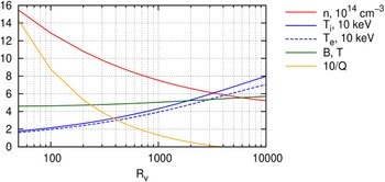
Dependence of plasma parameters (density n, ion temperature T
i
, electron temperature T
e
, vacuum magnetic field B and inverse fusion gain 10/Q) versus vortex section factor ( $R_{\textit{v}}$
).
$R_{\textit{v}}$
).

A purely deuterium–deuterium ‘primary’ fusion produces rather low power; to make the fusion reactor compact, the VOYAGER design uses ‘secondary’ fusion reactions with by-products (tritium and helium-3) to contribute to the overall fusion power, with an assumption that all the tritium produced in primary reactions is returned back into the plasma for the secondary reaction:
 \begin{equation}D+D\rightarrow \left\{\begin{array}{c@{\quad}c} 50\,{\% }\colon & p+T\\[3pt] 50\,{\% }\colon & n+{}^{3}\textit{He} \end{array}\right\},\quad D+T\rightarrow n+{}^{4}\textit{He},\quad D+{}^{3}\textit{He}\rightarrow p+{}^{4}\textit{He}.\end{equation}
The energy gain factor is
 \begin{equation}Q=\frac{P_{\textit{fus}}}{P_{\textit{heat}}},\quad P_{\textit{heat}}=P_{\parallel }+P_{\bot }+P_{\textit{r}}-P_{\textit{p}},\end{equation}
where P fus is the total fusion power, P p is the part of P fus released in charged products and spent for plasma heating, and P heat is the total external heat power introduced to the plasma.
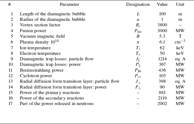
The listed equations were used to calculate fusion reactor parameters using BINP SB RAS proprietary calculation software, starting with fusion power P
fus
= 3 GW, and length and radius of diamagnetic bubble of 100 and 1 m, respectively (see figure 2). Notice the fusion gain of an open trap based reactor rises together with a vortex section factor, with ignition occurring at $R_{\textit{v}}$
= 3800 (P
heat
→ 0 and Q → ∞), see table 1.
$R_{\textit{v}}$
= 3800 (P
heat
→ 0 and Q → ∞), see table 1.
Parameters of reactor with ignited plasma.

The fusion power P
fus
, fusion gain Q and vortex section factor $R_{\textit{v}}$
are related to each other. For example, fusion gain Q rapidly rises with vortex section factor
$R_{\textit{v}}$
are related to each other. For example, fusion gain Q rapidly rises with vortex section factor $R_{\textit{v}}$
at a fixed fusion power P
fus
, as shown in figure 2. Understanding the relationship among these parameters is useful for reactor optimisation. Let us analytically consider the mode with fixed Q neglecting radial diffusion and cyclotron radiation for simplicity. The power balance equation (2.14) in this case gives
$R_{\textit{v}}$
at a fixed fusion power P
fus
, as shown in figure 2. Understanding the relationship among these parameters is useful for reactor optimisation. Let us analytically consider the mode with fixed Q neglecting radial diffusion and cyclotron radiation for simplicity. The power balance equation (2.14) in this case gives
 \begin{equation}P_{\parallel }=\left(\alpha -\frac{1}{Q}\right)P_{\textit{fus}}-P_{\textit{Br}},\end{equation}
where α is a fraction of fusion power that heats plasma. Fusion power and Bremsstrahlung power are both proportional to reactor length and density square as well as the right side of (2.15):
 \begin{equation}P_{\textit{fus}},P_{\textit{Br}}\sim Ln^{2}.\end{equation}
Parallel losses are defined by the density n and vortex section factor $R_{\textit{v}}$
:
$R_{\textit{v}}$
:
 \begin{equation}P_{\parallel }\sim \frac{n}{R_{\textit{v}}}.\end{equation}
Combining (2.15)–(2.17), one gets
 \begin{equation}R_{\textit{v}}\sim \frac{1}{\sqrt{P_{\textit{fus}}L}}.\end{equation}
Fusion power is proportional to VOYAGER reactor length since the heat dissipation via reactor walls is limited (see § 2.3.1 for more information), thus:
 \begin{equation}R_{\textit{v}}\sim \frac{1}{P_{\textit{fus}}}.\end{equation}
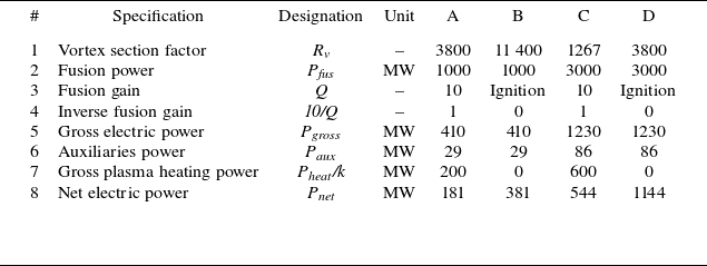
Thus, at a given fusion gain Q, the vortex section factor is inversely proportional to the reactor fusion power. It is reasonable to keep the vortex section factor $R_{\textit{v}}$
and fusion power P
fus
as low as possible to minimise plant complexity and cost, while keeping net electric power P
net
high to provide revenue, so balancing for Q, R
v
, P
fus
and P
net
is necessary to minimise LCOE. One can calculate several options for balancing listed in table 2. This table suggests the following.
$R_{\textit{v}}$
and fusion power P
fus
as low as possible to minimise plant complexity and cost, while keeping net electric power P
net
high to provide revenue, so balancing for Q, R
v
, P
fus
and P
net
is necessary to minimise LCOE. One can calculate several options for balancing listed in table 2. This table suggests the following.
-
(i) Options A and B suggest using low P fus (1000 MW) reactors to minimise the cost for reactor assembly. At this power level, high $R_{\textit{v}}$
is required to maintain reasonable Q. Options C and D use high P
fus
(3000 MW) to minimise
$R_{\textit{v}}$
. Notice designing a reactor with P
fus
higher than 3000 MW is not reasonable as it results in P
net
exceeding 1200 MW and thus is difficult to use in real-grid scenarios.
$R_{\textit{v}}$
is required to maintain reasonable Q. Options C and D use high P
fus
(3000 MW) to minimise
$R_{\textit{v}}$
. Notice designing a reactor with P
fus
higher than 3000 MW is not reasonable as it results in P
net
exceeding 1200 MW and thus is difficult to use in real-grid scenarios. -
(ii) Options A and C feature finite Q and thus require development of new, continuously operating heating systems (more on them next section), making cost predictions difficult. Thus, the cost and LCOE estimations for these set-ups were not calculated.
-
(iii) Options B and D have infinite Q due to sufficiently high
$R_{\textit{v}}$
and P
fus
, enabling us to design and estimate costs for VOYAGER components, specifically, plasma heating and other systems. Notice option B produces three times less net electric power, thus providing much lower revenue and requiring significant cost savings in both CAPEX and OPEX to achieve similar LCOE. Thus, option D was selected for further description in the article, though a qualitative comparison between options B and D is presented in § 3.


Options for balancing fusion power and vortex section factor in VOYAGER plant.

2.2. Power plant components design
2.2.1. Fusion chamber dimensions
Fusion power radiates from a plasma into a reactor wall and into expander sections in the form of neutrons and gamma-radiation. A fusion chamber wall should withstand such power, which limits the minimum chamber inner surface. Taking into account complete burn of tritium produced by the DD reaction (due to the tritium recycling system described later), 68 % of the total fusion energy (2002 MW) is released as fast neutrons (table 1). They immediately leave the fusion chamber after synthesis, passing through the fusion chamber first wall and are captured by a blanket. The acceptable neutron load on the first wall is estimated in the literature as 2.5–5 MW m−2 (Merola Reference Merola2009; Kuang et al. Reference Kuang2018; Lion et al. Reference Lion2025). For the VOYAGER option D with the highest expected fusion power (3000 MW) and assuming conservative 3 MW m−2 neutron load, the inner surface should be no less than 690 m2, translating to a 100 m long reactor central section with 1.1 m first wall radius. Those dimensions are large enough to accommodate plasma with dimensions proposed in § 2.2.2 and thus were used for subsequent cost estimations for reactor assembly.
2.2.2. Radiation protection
A significant portion of the plant energy is emitted as fast neutrons in the central section of the reactor requiring radiation protection for HTS coils. The rest of the energy is produced as fast ions that are absorbed by plasma receivers in expander sections with simpler radiation protection and heat dissipation design. The authors expect central section reactor components (wall, shielding, blanket and magnets) replacement every 25 years (maintenance period τ). Let us estimate the volume for protection as it influences magnet inner diameter, and overall system complexity and cost.
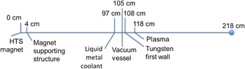
A blanket in the central section is placed between the plasma chamber and HTS magnets (figure 3). The blanket provides radiation protection for HTS magnets and collects heat for consequent conversion into electricity. The blanket consists of a tungsten first wall, vacuum vessel, liquid metal coolant (lead) and moderator (boron carbide) with a total 1.1 m thickness.
Central section cross-section. 0 cm signifies inner winding of HTS magnet, 218 cm signifies reactor axis centre.

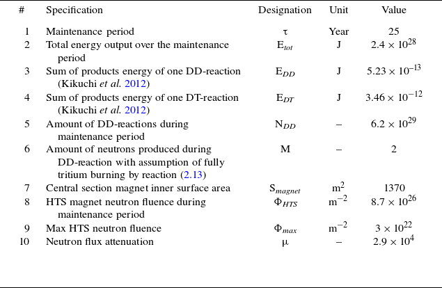
The HTS magnet should not be irradiated above the maximum HTS neutron fluence (Fischer et al. Reference Fischer, Prokopec, Emhofer and Eisterer2018) before maintenance (HTS magnet replacement). Neutron flux attenuation ( $\unicode{x03BC}$
) during the maintenance period is calculated with neutron fluence (
$\unicode{x03BC}$
) during the maintenance period is calculated with neutron fluence ( $\varPhi _{\textit{HTS}}$
) and values in the table 3 using (2.20)–(2.23).
$\varPhi _{\textit{HTS}}$
) and values in the table 3 using (2.20)–(2.23).
Parameters for radiation protection.

Neutron flux attenuation ( $\unicode{x03BC}$
) can be achieved with just 0.4 m of boron carbide (Thomas, Paluszek & Cohen Reference Thomas, Paluszek and Cohen2019) that can be located inside the 1.1 m thick blanket section, and thus enables blanket and magnet replacement within 25 years or 3 times during the 80-year expected plant lifetime.
$\unicode{x03BC}$
) can be achieved with just 0.4 m of boron carbide (Thomas, Paluszek & Cohen Reference Thomas, Paluszek and Cohen2019) that can be located inside the 1.1 m thick blanket section, and thus enables blanket and magnet replacement within 25 years or 3 times during the 80-year expected plant lifetime.
 \begin{equation}E_{\textit{tot}}=P_{\textit{fus}}\tau,\end{equation}
 \begin{equation}N_{\textit{DD}}=\frac{E_{\textit{tot}}}{(E_{\textit{DD}}+E_{\textit{DT}})},\end{equation}
 \begin{equation}\varPhi _{\textit{HTS}}=\frac{\textit{MN}_{\textit{DD}}}{S_{\textit{magnet}}},\end{equation}
 \begin{equation}\mu =\frac{\varPhi _{\textit{HTS}}}{\varPhi _{\textit{max}}}.\end{equation}
2.2.3. Fuel handling system: injection, removal of fusion products and separation
Deuterium fuel enriched with by-product tritium is injected into the reactor via pellets similar as Baylor et al. (Reference Baylor2009) to keep the tritium concentration at 5 % in the plasma. The key feature of open traps is the natural channel for removing impurities and reaction products. VOYAGER is a ‘flow’ system, so the accumulation of impurities, including helium, heavy (from the wall) and light (such as deuterium) elements, is not expected. All substances from the plasma escape through the mirror section rather equally – the retention times for all elements are similar. The deuterium flow required to maintain balance is approximately 800 eq. A and fusion reactions give approximately 2–3 eq. A of helium (table 1); the ratio of their densities will be approximately less than 1 %. With such density ratios, even a low degree of purification would not affect plasma ignition (Z eff ). Several approaches are suitable for separation: membrane diffusion (Willms Reference Willms2016) or gas centrifuge. Notice that separation is used not only for removal of non-reactive isotopes (specifically, helium) but also to acquire tritium for re-injection into plasma for increased fusion power (see § 2.2.2).
2.2.4. Magnet system design
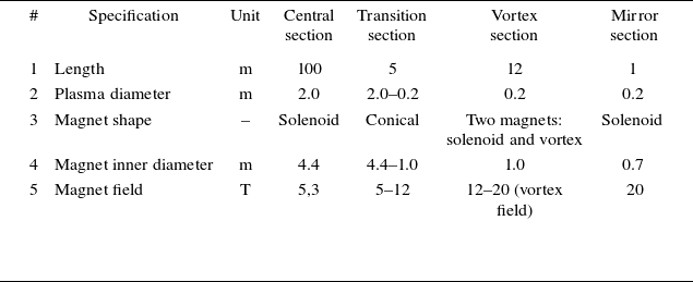
The VOYAGER magnet system comprises four main components: central section, transition section, vortex section and mirror section (figure 1). General specifications for each section are given in table 4. The central section is designed modularly: it comprises several solenoids covering its whole length with spacing for diagnostics, piping, plasma heating, etc. Solenoids provide a sufficient magnetic field (5 T in normal operation, see figure 2), while providing enough space for radiation protection blanket. Modular design provides ease of assembly and maintenance. Vortex and mirror sections are designed with a 12 T magnet field, with a total length of 12 m each. The transition section is necessary for combining central and vortex sections, ensuring smooth field transition between central and mirror sections.
Magnet system specification.

Magnet system size, material usage and cost calculations are based on coil strength, HTS current density and magnet field modelling developed by SuperOx LLC. Strength estimations use the free-turn model taking into account the internal radius of the magnet (the most stressed part). The maximum load on the HTS cable does not exceed 800–1100 MPa, which is lower than the load values in similar projects (Dunn Reference Dunn2024) and was demonstrated by Moyzykh (Reference Moyzykh2023). The magnetic field is designed using the current density in the range of 100–200 A mm−2 (achievable for HTS (Mounet Reference Mounet2022)).
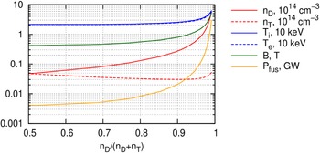
Dependence of plasma parameters versus the relative deuterium density for the second startup stage.

2.2.5. Fusion plasma startup and plasma heating equipment
During power production, the VOYAGER reactor operates in ignited state (see § 2.2.2 for details) and does not require plasma heating, essentially due to having high enough fusion power P
fus
and vortex section factor $R_{\textit{v}}$
. However, during startup of the reactor fusion power starts from zero, requiring a dedicated startup procedure divided into two stages.
$R_{\textit{v}}$
. However, during startup of the reactor fusion power starts from zero, requiring a dedicated startup procedure divided into two stages.
-
(i) The first stage assumes gas-dynamic plasma confinement, high external heating power and significant tritium content (provided externally). The magnetic field is reduced in the central reactor section, while in the other sections (vortex, mirror, expander), it remains normal. At the first stage, the plasma pressure increases to achieve ‘diamagnetic bubble’ configuration and ignition.
-
(ii) The second stage assumes the transition to a pure deuterium reactor. The portion of tritium in the plasma gradually decreases, along with a decrease in the reaction rate, which is compensated by an increase in density, temperature and magnetic field.
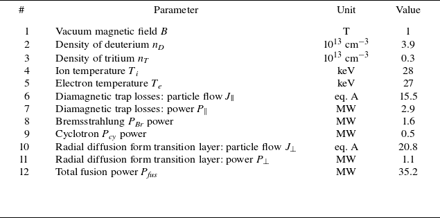
Let us consider the second stage first. It is modelled in the same way as in § 2.2.2, but external sources of tritium are taken into account. Plasma is already ignited and the goal is to decrease tritium content so the reactor can self-sustain its tritium content. To reduce the tritium content, the fusion power increases so that the plasma remains at the border of the ignition mode. The dependence of plasma parameters on the relative density of deuterium is shown in figure 4. The right edge corresponds to a pure deuterium reactor with a plasma tritium content of 0.9 %. This is the final configuration of the second stage. The initial configuration is selected based on the following considerations. On the one hand, the plasma parameters should be noticeably lower than the final ones. On the other hand, the magnetic field must remain large enough for the Larmor radius of fusion products to be acceptable. Thus, the initial configuration of the second stage was selected at 93 % D + 7 % T plasma, see table 5.
Initial configuration of the second startup stage.

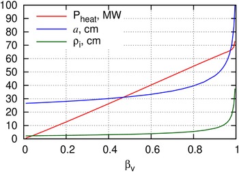
Dependence of plasma parameters on the relative pressure for the first startup stage.

As the reactor consumes external tritium during this stage, it is necessary to estimate its content to include the tritium cost in reactor OPEX maintenance. The duration of the startup second stage is limited by the magnet field ramp-up of the central section, taking 45 minutes, corresponding to up to 15 g of tritium consumption.
Now, let us consider first start up stage. Initially, the plasma at the first start-up stage has an open trap gas-dynamic plasma confinement (without a ‘diamagnetic bubble’). Plasma parameters are estimated similar to § 2.2.2, but with the following three main changes.
-
(i) The absence of a ‘bubble’ cancels the condition (2.7). Instead, the relative plasma pressure
$\beta_{\bot}$
is introduced as a parameter:(2.24)where B is the vacuum magnetic field and B pl is the reduced magnetic field in the plasma. The value of the vacuum field is chosen the same as at the beginning of the second stage: B = 1 T, see table 5.
\begin{equation}\beta _{\bot }=\frac{16nT}{B^{2}}, \quad B_{\textit{pl}}=\sqrt{1-\beta _{\bot }}B,\end{equation}
-
(ii) The axial confinement time instead of (2.9) becomes gas-dynamic, taking into account beta and the vortex sections factor:
(2.25)
\begin{equation}\tau _{\parallel }=\frac{R_{\textit{v}}}{\sqrt{1-\beta _{\bot }}}\tau _{\textit{gd}}.\end{equation}
-
(iii) The plasma radius is no longer constant. Instead, the magnetic flux Φ = na 2 B pl is assumed to be conserved. The magnitude of the magnetic flux Φ is determined by the magnetic flux of the transition layer at the beginning of the second start-up stage. The term for the cyclotron loss power is also different from (2.11). However, since this power turned out to be small, the exact expression is not presented in the text.


The results of the evaluation of plasma parameters for the first start-up stage are shown in figure 5. The highest relative pressure value of $\beta_{\bot} = 99.5\,\%$
corresponds to the conditions of the ‘diamagnetic bubble’ formation with up to 70 MW plasma heating power required. Notice that modern studies demonstrate the formation of a ‘diamagnetic bubble’ in milliseconds (Roche et al. Reference Roche2025), indicating the first start up stage of the VOYAGER plant should occur in the sub-second format.
$\beta_{\bot} = 99.5\,\%$
corresponds to the conditions of the ‘diamagnetic bubble’ formation with up to 70 MW plasma heating power required. Notice that modern studies demonstrate the formation of a ‘diamagnetic bubble’ in milliseconds (Roche et al. Reference Roche2025), indicating the first start up stage of the VOYAGER plant should occur in the sub-second format.
Let us consider how to setup 70 MW, 1-second plasma heating. At present, the Budker Institute has completed the development of a 100 keV, 1-second impulse – class injectors (Belchenko et al. Reference Belchenko2018; Shikhovtsev et al. Reference Shikhovtsev2024) for use in magnetic plasma confinement facilities. A batch of similar injectors can be used in the VOYAGER plant to achieve the necessary power. The injectors have a deuterium ion beam with a current of 75 A, the equilibrium yield of deuterium atoms at an energy of 100 keV is 0.44 and the power of the fast deuterium neutral beam of 3.3 MW. The capture coefficient of the beam injected into the inner region of the plasma is estimated as 0.92. As a result, the power injected into the plasma from one deuterium neutral beam is 3.0 MW. So to achieve a 70 MW heating startup power, 24 deuterium neutral beams are necessary – a number which was used in the later economic calculations.
The injectors are planned at both ends of the central section with an injection angle in the vicinity of 45°. Shutters separate injectors from fusion radiation after startup. Notice that the injectors are purely deuterium (tritium is injected separately via mixed D and T pellets) so as not to adapt existing technology to new beam atoms.
After initial heating of the enriched fuel reaches the ignition state, the second stage begins, featuring an absence of external heating, gradual increase in fusion power and reduction of tritium content to self-sustainable volume (roughly 1 %), reaching full fusion power.
2.2.6. Conversion to electric power
Most fusion power is released into the central section blanket (88 %, including neutrons, Bremsstrahlung and cyclotron radiation, radial diffusion from the transition layer), while the rest is absorbed in expander sections (12 %, diamagnetic trap losses). This energy is converted to electric power similarly to conventional liquid metal coolant nuclear power plants (Patel Reference Patel2016), which are also suitable for fusion (Rapisarda et al. Reference Rapisarda, Fernández-Berceruelo, García, García, Garcinuño, González, Moreno, Palermo, Urgorri and Ibarra2021).
The conversion system consists of two separated circuits: primary liquid metal circuit – for cooling the irradiated components (first wall, limiters, blanket, expanders etc.); and secondary water circuit – to power the turbines, with heat exchanger between the circuits. Magnetic field effects on the liquid metal flow are eliminated by placing coolant piping along the reactor (horizontal direction) to avoid coolant flow in the gradient magnetic field.
Due to the high neutron flux central section, the blanket contains a neutron moderator (boron carbide, see § 2.4) to absorb neutrons, which generates heat. This heat is collected with cooling pipes running through the moderator by liquid metal coolant, comprising a primary cooling circuit, operating at 540 °C and near-atmospheric pressure. The estimated coolant flow rate is 2400 kg s−1, proposed by Candido et al. (Reference Candido2026). A possible coolant piping material can be Inconel 718 (Kuang et al. Reference Kuang2018) with a lifetime of 25 years given a moderately low operating temperature. The second circuit operates in subcritical conditions (7 MPa, 326 °C) or super-critical conditions (25 MPa, 530 °C). For such operational temperatures, one can expect an efficiency N in the range from 36 % (subcritical conditions (ROSATOM Group Reference Roche2025)) up to 46 % (for supercritical conditions (Kirillov et al. Reference Kirillov, Pomet’ko, Smirnov, Grabezhnaia, Pioro, Duffey and Khartabil2005)). The lower margin is similar to older nuclear power plants; the higher one to modern designs. Thus, with 3000 MW fusion power capacity, the gross electric power P gross is between 1080 and 1380 MWe (heat to electricity conversion efficiency 36 %–46 %). The reactor’s self-consumption is estimated at 7 % of the gross power (Meekal & Majid Reference Meekal and Majid2024), and consequently, net electric power is expected in the 1004–1283 MW range.
Construction cost estimation.

2.3. Cost estimations
2.3.1. Construction cost estimation
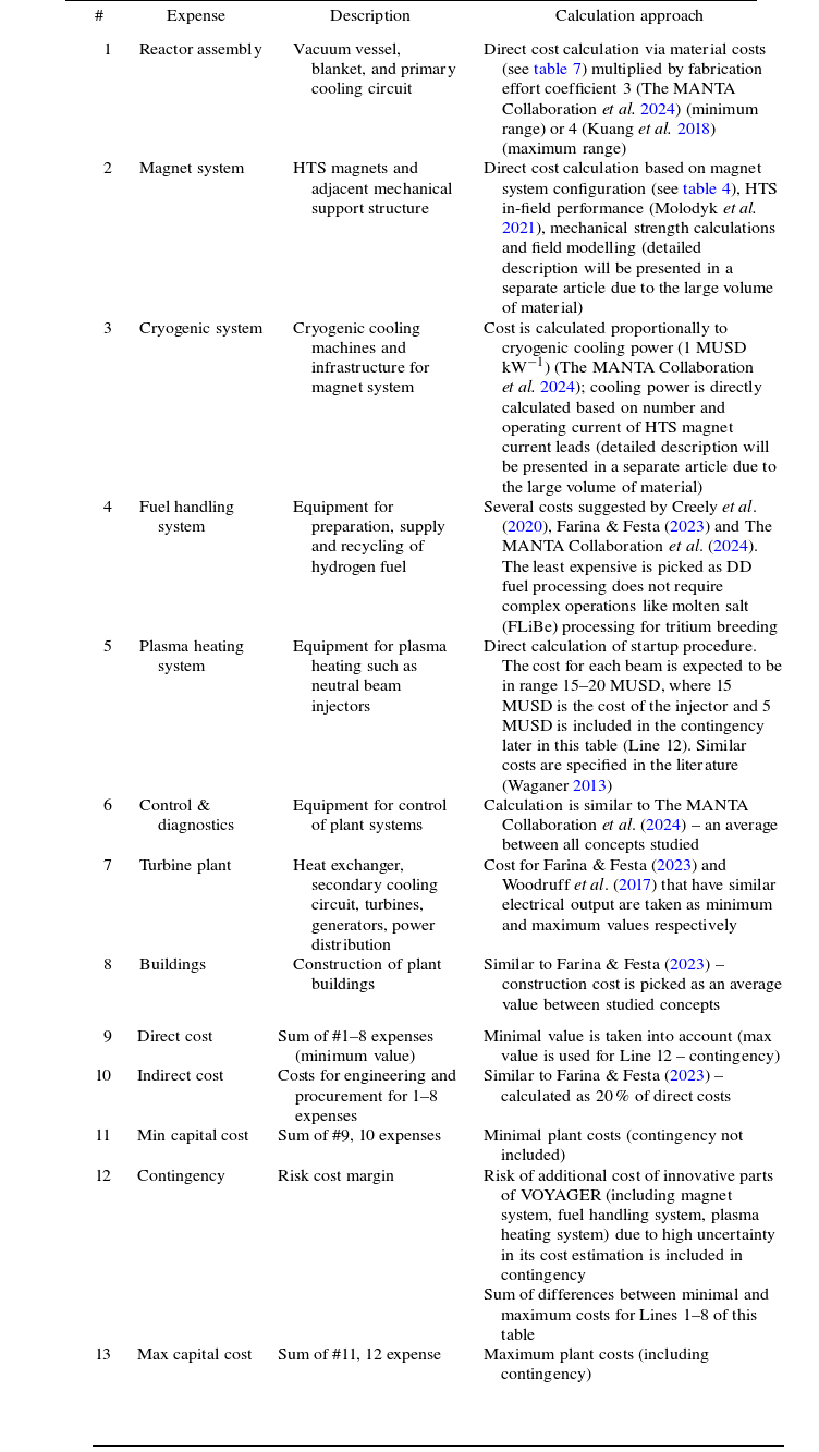
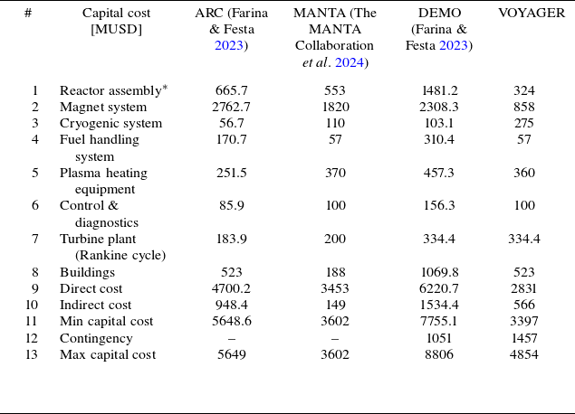
Construction costs were determined using a method similar to that for other fusion plant concepts described by Baylor et al. (Reference Baylor2009), Kuang et al. (Reference Kuang2018), Farina & Festa (Reference Farina and Festa2023), Shikhovtsev et al. (Reference Shikhovtsev2024) and The MANTA Collaboration et al. (2024). The expense list, along with their definition and approach for calculation for the VOYAGER concept, is given in table 6. The costs were calculated in the range to account for contingency and to demonstrate sensitivity to cost variation of different expenses. The range between min capital cost and max capital cost can be used as an estimate for subsequent sensitivity analysis.
The plant construction time is expected to be 5–8 years, similar to nuclear plants (Lovering, Yip & Nordhaus Reference Lovering, Yip and Nordhaus2016). However, since a fusion plant does not store significant volumes of fissile material and thus requires less effort for certification and contingency reasons, it is safe to assume the construction time will be at the minimum range, close to 5 years.
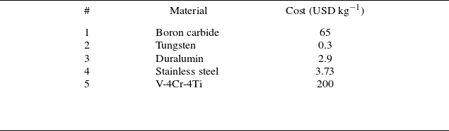
Material cost (stock exchange prices on January 2025).

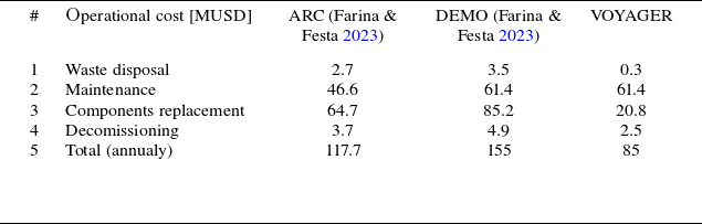
2.3.2. Operation (maintenance) cost estimation
Plant maintenance consists of the following operations.
-
(i) Waste disposal covers removal and processing of plant fissile materials, which was studied by Kuang et al. (Reference Kuang2018) and Farina & Festa (Reference Farina and Festa2023) to be in the range of 2.7–3.3 MUSD annually. Since the VOYAGER plant does not operate with large quantities of fissile material (no tritium breeding), waste disposal cost can be expected to be as low as 10 % of a tritium breeding reactor, giving a 0.3 MUSD annual waste disposal cost.
-
(ii) Maintenance – studied by Farina & Festa (Reference Farina and Festa2023) as well, gives 61.4 MUSD for high-power plant (EUROfusion News 2022) and 46.6 for a lower power (Kuang et al. Reference Kuang2018). Since the high-power plant (EUROfusion News 2022) has a similar power to the VOYAGER plant, 61.4 MUSD was used as an estimation.
-
(iii) Components replacement was calculated directly, with the total component replacement cost esteemed over the plant lifetime (80 years) and averaged annually:
-
(a) first wall and blanket replacement due to radiation erosion – 231 MUSD every 25 years, replacement time – 3 months;
-
(b) magnet system replacement due to radiation damage to superconductor material – 322 MUSD every 25 years, replacement time – 3 months;
-
(c) tritium for start-up after magnet and blanket replacement – 15 g (authors expert guess), 30 000 USD g−1 (The MANTA Collaboration et al. 2024); total for one startup – 0.45 MUSD.
-
-
(iv) Decommissioning: 3 % of operation cost (Farina & Festa Reference Farina and Festa2023).
Costs for operation were combined to provide the resulting value, being 85 MUSD annually (see § 3, table 9). Since this value is the lowest in the range of similar commercial plant projects (Kuang et al. Reference Kuang2018, EUROfusion News 2022), it may be necessary to assume the resulting plant may be in the range between maximum and minimum operating costs (85–155 MUSD) as a risk factor for sensitivity analysis.
Maintenance downtime for fusion plants is studied by Farina & Festa (Reference Farina and Festa2023), providing a capacity factor between 71 % and 88 %, which is in a similar range to contemporary nuclear power plants (Nuclear Energy Institute 2024) and thus feels like a suitable range for the VOYAGER plant concept as well.
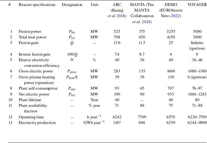
Comparison between several plant projects.

3. Results
The resulting plant technical specifications are summarised in table 8. The data for the other studied concepts are also presented in the table to provide a comparison.
The cost calculation results for construction and operation are given in tables 9 and 10, respectively, also with other plant concepts as a reference. Notice that the VOYAGER plant features the highest contingency value, demonstrating a high safety factor is included into the plant design.
Capital cost.

Operations cost.

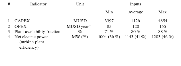
The resulting VOYAGER key performance indicators that influence commercial viability (specifically CAPEX, OPEX, and plant availability fraction and turbine efficiency) are summarised in table 11.
VOYAGER plant key indicators.

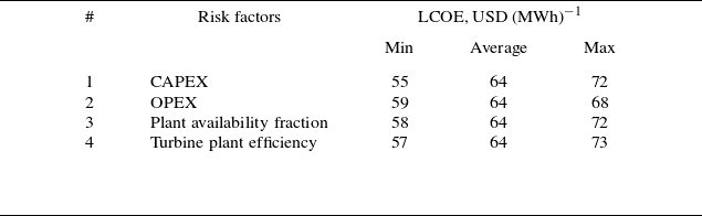
Using the average values for VOYAGER plant key indicators and their ranges for as risk factors, LCOE value and sensitivity were calculated (table 12). The VOYAGER plant LCOE (64 USD (MWh)−1) is significantly lower than other tokamak fusion plants proposed, which have this value in the range of 125–400 USD (MWh)−1.
VOYAGER plant LCOE sensitivity analysis.

It is reasonable to discuss VOAYGER design Options B and D specified in table 2 in relation to its LCOE. Option B has a lower fusion power and provides three times less net electric power, which increases its LCOE due to lower power production and less revenue, requiring lower CAPEX and OPEX to compensate. One can provide several assumptions in costs associated with low-power Option B:
-
(i) reactor assembly – negligible cost reduction (may save some costs due to less neutron shielding while overall dimensions remain the same);
-
(ii) magnet system – cost increase due to complexity of high-
$R_{\textit{v}}$
vortex sections by a factor of 1.6; -
(iii) cryogenics, fuel handling, control, diagnostics – no cost savings due to similar, non-power related equipment;
-
(iv) turbine plant, buildings – may provide savings, reducing cost by up to 3 (proportional to reduction in power).

Given these assumptions, one can expect Option B LCOE at 189 USD (MWh)−1, significantly higher than Option D featured throughout the article.
In comparison with DEMO (EUROfusion News 2022), the VOYAGER plant features comparable net electric power and operating cost, but has significantly less construction cost (probably due to simpler magnet system design and use of modern HTS technology). An open trap WITAMIR (Badger et al. Reference Badger1980) has much higher CAPEX (11 BUSD, CAPEX adjusted for inflation from 1980 to 2025) since it lacks modern options of HTS and vortex magnet sections. Stellarator (Prost & Volpe Reference Prost and Volpe2024) uses HTS magnets but the complexity of the stellarator magnet structure still makes it CAPEX cost higher by 29 %–53 %. Other plants like those that ARC (Kuang et al. Reference Kuang2018) and MANTA (The MANTA Collaboration et al. 2024) have 6–15 times lower net electric power (and, consequently, revenue) along with comparable construction costs, severely limiting their LCOE.
VOYAGER, having high net electric power, low CAPEX and comparable OPEX provide a competitive proposition even with conventional energy sources like nuclear power plants, which is reflected in its LCOE in the 55–73 USD (MWh)−1 range.
4. Discussion
While the VOYAGER plant concept delivers promising technical and economical specifications, it is necessary to discuss propositions made during development of this paper. The key propositions are as follows.
-
(i) Proof of basic open trap fusion principles:
-
(a) ‘diamagnetic bubble’ confinement (size of transition layer, reliability of expression (2.9) and determining the exact value of
$\eta$
parameter, mentioned in § 2.2.2); -
(b) confinement of MeV-range particles and their slowing-down in a thermal plasma;
-
(c) plasma stabilisation techniques, e. g. conducting wall (Kotelnikov, Prikhodko & Yakovlev Reference Kotelnikov, Prikhodko and Yakovlev2023);
-
(d) radial diffusion from the transition layer, design of the limiters;
-
(e) startup scenario and the required plasma heat power;
-
(f) effects of cyclotron radiation absorption by the first wall.
-
-
(ii) Achievement of key vortex section indicators, including:
-
(a) compatibility of diamagnetic trap and vortex section;
-
(b) upscaling vortex section factor
$R_{\textit{v}}$
up to 3800 unit range (current experimental record is 17 (Skovorodin et al. Reference Skovorodin2023)); -
(c) possibility to fill the region in the velocity space corresponding to the trapped ionsFootnote 1 ;
-
(d) maintaining the plasma rotation inside the vortex section, application the voltage of the order of hundreds of kilovolts.
-
-
(iii) Technology availability:
-
(a) high field and size HTS magnet coils and vortex sections;
-
(b) heating systems with a power of approximately 70 MW for startup;
-
(c) accumulation of impurities in plasma, possibility of achieving Z eff coefficient (Postupaev et al. Reference Postupaev, Sudnikov, Beklemishev and Ivanov2016) in the vicinity of 1;
-
(d) separation of a pumped-out gas, specifically protium, deuterium and tritium for re-use in fusion;
-
(e) neutron shielding, heat removal from the first wall and limiters.
-


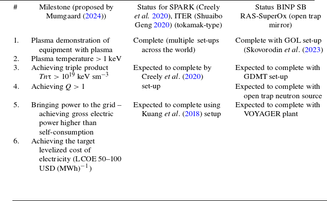
The first and second propositions can be tested using a set-up called GDMT (Gas-Dynamic Multiple-Mirror Trap) proposed by Skovorodin et al. (Reference Skovorodin2023). Such a set-up, if equipped with vortex sections with R v in the range above 300 may have triple product (temperature, density, lifetime) Tnτ in the 1019 keV sm−3 range, making it a significant milestone in commercial fusion power by Mumgaard (Reference Mumgaard2024) (see table 13 for reference), yet to be achieved by leading fusion research projects – SPARC (Creely et al. Reference Creely2020) and ITER (Shuaibo Geng Reference Shuaibo Geng2020). Compared with the mentioned projects, GDMT is a significantly more economic enterprise, having construction cost of orders below (150–200 MUSD), which makes VOYAGER plant concept even more promising.
Comparisons between milestones for VOYAGER plant and Mumgaard (Reference Mumgaard2024).

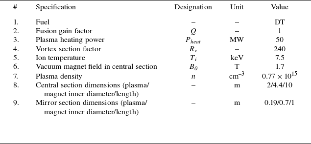
For the third proposition, the technology availability requires more effort and should be tested on a separate set-up. It is necessary to have this set-up designed as close to the VOYAGER plant (specifically blanket, magnet system, plasma heating, etc.) to fully test the technology while using minimal materials and effort for cost reduction. This can be achieved due to the VOYAGER plant modular design. The test set-up, called an open trap neutron source, comprises a single, identical to the VOYAGER plant, central section (10 m length), equipped with simplified mirror sections ( $R_{\textit{v}}$
∼ 240) and plasma heating equipment modules with a total heating power of 50 MW (see table 14). Using tritium as a fuel, such a module set-up achieves a fusion energy gain (Q) of one, making it another milestone towards a commercially viable fusion plant. The costs of this step can be estimated roughly as half of the VOYAGER plant cost (less than 1.7 BUSD).
$R_{\textit{v}}$
∼ 240) and plasma heating equipment modules with a total heating power of 50 MW (see table 14). Using tritium as a fuel, such a module set-up achieves a fusion energy gain (Q) of one, making it another milestone towards a commercially viable fusion plant. The costs of this step can be estimated roughly as half of the VOYAGER plant cost (less than 1.7 BUSD).
Plant module test set-up.

After testing the technology using a neutron source set-up, the plant components (magnet and reactor assembly, plasma heating equipment) can be multiplied, upscaling the neutron source into the fully operational VOYAGER plant. The cost of this step can be expected to be less than 2.4 BUSD due to the VOYAGER plant modular structure of the magnet, reactor and plasma heating systems. Thus, the total cost of construction of the VOYAGER plant, including research and development, does not exceed 5 BUSD, which is substantially lower in comparison with other fusion power plant projects.
5. Conclusions
The paper proposes a novel concept of a fusion power plant named VOYAGER. The plant features an open trap magnet system configuration with vortex magnet sections and extensive use of modern high-temperature superconductor materials. These features provide this plant concept with a competitive advantage in terms of higher electricity generation volume, competitive construction and operation costs, as well as less effort in research and development. The competitive advantage is reflected by the LCOE values achieved, being significantly lower in comparison with other fusion plant concepts and comparable to most contemporary energy sources. The low energy cost value along with reduced research and developments costs project the VOYAGER plant as a commercially viable proposition.
Acknowledgements
The authors are grateful to Alena Pleshakova for the design of figure 1 along with the help with overall article formatting and editing.
Editor Cary Forest thanks the referees for their advice in evaluating this article.
Declaration of interests
The authors report no conflict of interest.



 Open access

