


1. Introduction
Multi-mode products are able to realize a changing set of functions across modes, thus providing the functionality of multiple single-mode products while offering the lower monetary, spatial, and time costs of one alternative product (Weaver, Wood, & Jensen Reference Weaver, Wood and Jensen2008). Figure 1 shows a hierarchical classification of multi-mode products and representative examples (Aidacare 2024; Navaris 2024; Polygons 2024) of each terminal class: 1. non-reconfigurable, 2. modular, and 3. structurally transforming. This work focuses on addressing the design difficulties of structurally transforming multi-mode products (also called transformers (Weaver et al. Reference Weaver, Wood and Jensen2008) or structurally adaptable (Benli Reference Benli2023)).

There are distinct benefits and drawbacks in the design and use of products that belong to each of the three terminal classes from Figure 1. The relatively simple architecture of non-reconfigurable multi-mode products reduces cost but often limits the number or variety of functions across modes. Modular products overcome this limitation with additional components allowing for numerous, complex, and specialized functions. However, as with non-reconfigurable multi-mode products, the use of a shared platform for all modes often results in compromised product performance. Modular products’ additional specialized components also reduce product ease of use and counteract the space-saving benefits of a multi-mode product with increased total weight and volume (Benli Reference Benli2023). Structurally transforming multi-mode products capitalize on the benefits of having reconfigurable components to increase function variety while improving ease-of-use over modular products by reusing the reconfigurable components across modes, also reducing total weight and volume. These benefits are, unfortunately, eclipsed by the increased product design difficulty, and the resulting higher design cost, that arise due to multiple product modes and designed component-sharing (Weaver et al. Reference Weaver, Wood and Jensen2008).
This paper presents a framework to address these difficulties unique to the design of structurally transforming multi-mode products by building upon the standard design process to connect existing disjointed methods. The proposed framework aims to systematically, cohesively, and comprehensively address four goals for a design process for structurally transforming multi-mode products identified by Weaver et al. (Reference Weaver, Wood and Jensen2008):
-
1. to help designers identify the possibility/need for a structurally transforming multi-mode product,
-
2. to understand all constraints on the design of such a product,
-
3. to guide the exploration of the large solution space for such a product, and
-
4. to balance the advantages and disadvantages of transformations between multiple modes.
The framework is broken down into distinct steps, each of which is first described at a high level, followed by a discussion of a case study that was co-developed alongside the framework itself. The case study, involving the design of a three-mode product that addresses an overarching need for furniture that is safe and supportive for young children of multiple ages, explores the framework at a high level of detail. This discussion includes the presentation of tabular tools that were developed during the execution of the case study to organize information within each step.
2. Existing Design Methods
Design difficulties for all classes of multi-mode products impact one or more of the three major design stages: Problem Definition, Conceptual Design, and Embodiment Design (Pahl et al. Reference Pahl, Beitz, Feldhusen and Grote2007). The impact of the modes for non-reconfigurable products is minimal and restricted to the Problem Definition stage through the need for modal product requirements. A method to define a product’s modes by analyzing all expected functions and clustering complementary functions has been applied to non-reconfigurable products (Liu et al. Reference Liu, Hildre, Zhang and Rølvåg2015, Reference Liu, Hildre, Zhang and Rølvåg2016). Non-reconfigurable products with multiple digital modes, like the ones explored by Liu et al. (Reference Liu, Hildre, Zhang and Rølvåg2015, Reference Liu, Hildre, Zhang and Rølvåg2016), have few physical design complexities during the Conceptual Design and Embodiment Design stages as switches and control logic, rather than physical transformations, are used for mode transitions which do not result in component-sharing. Non-reconfigurable products that transition between modes via changes in user interaction have equally few additional considerations in these stages.
Multi-modal design of modular products is largely confined to the Embodiment Design stage as 1. shared functions between modes are identified, 2. platforms performing shared functions and mode-specific modules are designed, and 3. a common interface is incorporated to connect the modules to the platform (Singh et al. Reference Singh, Walther, Krager, Putnam, Koraishy, Wood and Jensen2007; Ulrich, Eppinger, & Yang Reference Ulrich, Eppinger and Yang2015). Research to increase product adaptability and extend product life span has yielded additional relevant design process methods and optimization techniques (Gu, Hashemian, & Nee Reference Gu, Hashemian and Nee2004; Gu, Xue, & Chen Reference Gu, Xue, Chen and Bernard2011; Xue et al. Reference Xue, Hua, Mehrad and Gu2012; Martinez & Xue Reference Martinez and Xue2016).
Unlike non-reconfigurable or modular products, structurally transforming multi-mode products require additional design considerations in all three design process stages. As with non-reconfigurable multi-mode products, modal requirements must be defined during the Problem Definition stage. However, as any appropriate transformation method can be used to transition between modes, additional requirements describing the product’s transformation must also be characterized. The majority of existing case studies neglect this crucial step in the design process by starting from an already-defined problem (Skiles et al. Reference Skiles, Singh, Krager, Seepersad, Wood and Jensen2006; Liu et al. Reference Liu, Hildre, Zhang and Rølvåg2015; Liu et al. Reference Liu, Hildre, Zhang and Rølvåg2016; Kalimuthu et al. Reference Kalimuthu, Hayat, Elara and Wood2022).
The complexity from additional requirements is carried through the Conceptual Design stage, where the form of each of the product’s modes must be chosen through an evaluation of compatibility both with the other modes and with the transformation methods used. A method presented by Kalyanasundaram & Lewis (Reference Kalyanasundaram and Lewis2014) guides the combination of two single-mode products into a reconfigurable or non-reconfigurable multi-mode product (depending on the degree of component sharing) but is time-consuming and limited to the design of two-mode products. Additional research has yielded concise ways to represent transformation methods and ways to use these representations in the design process (Skiles et al. Reference Skiles, Singh, Krager, Seepersad, Wood and Jensen2006; Singh et al. Reference Singh, Walther, Krager, Putnam, Koraishy, Wood and Jensen2007; Singh et al. Reference Singh, Skiles, Krager, Wood, Jensen and Sierakowski2009; Wang et al. Reference Wang, Kuhr, Kaufman, Crawford, Wood and Jensen2009; Haldaman & Parkinson Reference Haldaman and Parkinson2010; Kalimuthu et al. Reference Kalimuthu, Hayat, Elara and Wood2022; Zhang et al. Reference Zhang, Cao, Peng, Tan, Liu and Zhang2022). However, these methods do not ensure a comprehensive exploration of the solution space as the transformations represented in the methods are extracted from existing product cases, thus potentially neglecting novel solutions. Guidelines for concept exploration and evaluation and criteria for choosing an appropriate concept selection method are presented in Literman, Cormier, & Lewis (Reference Literman, Cormier and Lewis2012), but the work does not offer a systematic way to navigate a large number of possible concepts without unforeseen conceptual information loss.
As with many large design problems, the Embodiment Design stage is complicated by the competition between design specifications and the resulting coupling of design variables. In the case of structurally transforming multi-mode products, additional design variable couplings emerge from the sharing of components across modes through chosen transformation methods. The issue of navigating design variable couplings has been widely investigated through the development of optimization techniques, including methods specifically designed for reconfigurable products (Gadalla & Xue Reference Gadalla and Xue2020) and for modular products and product families (Lewis, Mattson, & Murray Reference Lewis, Mattson and Murray2010; Bayrak et al. Reference Bayrak, Collopy, Papalambros and Epureanu2018) as well as an array of multi-objective methods and algorithms (Martins & Lambe Reference Martins and Lambe2013; Tanabe & Ishibuchi Reference Tanabe and Ishibuchi2020; Pereira et al. Reference Pereira, Oliver, Francisco, Cunha and Gomes2022) to address of wide variety of design problems. Any of these methods can be applied to a structurally transforming multi-mode product.
3. Framework for the Design of Structurally Transforming Multi-Mode Products
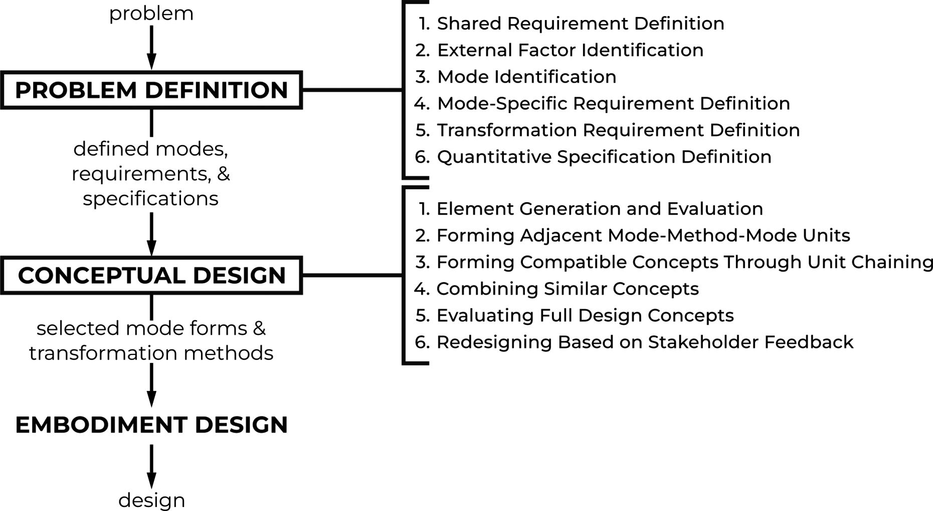
The framework is grounded in the standard process for the design of single-mode products with additional steps added to the design stages most affected by the sharing of requirements, of specifications, and of components across the modes: Problem Definition and Conceptual Design. To address these design difficulties systematically, this framework proposes a breakdown of the two stages into multiple easy-to-follow steps, as shown in Figure 2, that link together available design methods previously discussed in literature.
Each of the framework’s two stages is broken down into six ordered steps.
3.1. Stage 1: Problem Definition
The framework’s first goal: to help designers identify the possibility/need for a structurally transforming multi-mode product, has been addressed by Weaver et al. (Reference Weaver, Wood and Jensen2008) through the definition of three possible indicators:
-
1. The system needs packaging for portability and deployment.
-
2. Multiple systems would be more convenient if consolidated into one system.
-
3. Multiple systems have dissimilar configurations, but share common material and/or energy flow.
For products that meet one or more of these indicators, the completion of the second goal: to understand all constraints on the design of such a product, is addressed by first understanding what should be similar across all modes and why the modes have differences in the first place. Identifying this allows the designer to understand what should be different across modes and, in doing so, define when and how the product should transform. This analysis facilitates the development of a set of functional requirements for the product as a whole as well as the individual sets of requirements defining each mode and each transformation method.
3.1.1. STEP 1.1: Shared Requirement Definition
Before defining the product’s modes, it is first important to understand what will be shared across all modes such that the new product is a solution to the identified need. In product cases that qualify for the second and third indicators, the identified need could alternatively be met by multiple products; an analysis of the commonality between these multiple products will yield a set of shared requirements that must be met regardless of the new product’s current mode. Singh et al. (Reference Singh, Walther, Krager, Putnam, Koraishy, Wood and Jensen2007) describe a method to determine a product’s shared requirements in the case of a multi-mode product without readily available alternative single-mode products through a hierarchical exploration of the problem. The method described by Liu et al. (Reference Liu, Hildre, Zhang and Rølvåg2015, Reference Liu, Hildre, Zhang and Rølvåg2016) to cluster complementary functions could also be used here to divide product functions into shared and mode-specific requirements, particularly in the case of products with mechatronically controlled transformations. Similarly, other alternative system modeling approaches can be used to organize product requirements such that the similarities and differences between the product’s modes are clearly defined.
3.1.2. STEP 1.2: External Factor Identification
To understand the division between the product’s modes, it is important to understand the external factor that would prompt the need for multiple products. Examples of possible external factors include, but are not limited to, day/night, space, temperature, season, user needs, or discrete tasks. This factor, whether categorical, discrete, or continuous, must be identified and ordered according to its value for later use in differentiating the modes.
3.1.3. STEP 1.3: Mode Identification
The division between the modes can be defined by the external factor reaching a signal value that flags the need for a different set of requirements for the product. The transformation points for the product can then be defined at each signal value, thus implicitly defining the product’s modes between transformation points.
3.1.4. STEP 1.4: Mode-Specific Requirement Definition
The initially shared set of product requirements should then be differentiated between modes through the definition of mode-specific requirements as 1. modified shared requirements through changes to the application of the shared requirements or 2. unique modal requirements through the addition of new requirements for a single mode. These requirements in addition to any remaining, unchanged shared requirements describe the necessary features and functionality that should be accomplished within each of the product’s modes.
3.1.5. STEP 1.5: Transformation Requirement Definition
Structurally transforming multi-mode products have integrated, yet initially undefined transformation methods between each pair of modes. Thus, just as each mode has its own requirements, these methods will have their own sets of defined transformation requirements. Possible transformation requirements include, but are not limited to, constraints on transformation speed, required strength, power, sensors, adjustability, or reversibility. Similar to the mode requirements, some transformation requirements will be shared across all transformation points while some will be unique to a particular transformation. As transformation requirements refer to the same function in all cases: reconfigure, there cannot be modified shared transformation requirements as there is only one possible application for each of the requirements.
3.1.6. STEP 1.6: Quantitative Specification Definition
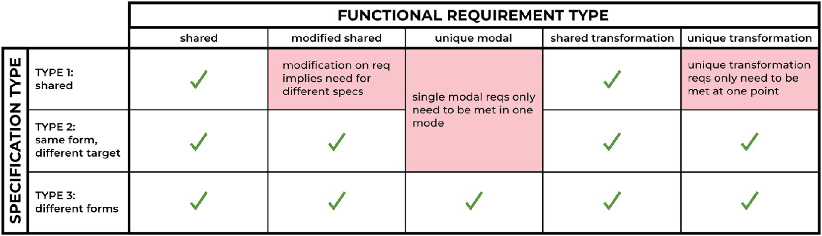
Quantitative specifications must be linked to the set of all functional requirements for the product. Three possible types of specifications can be linked to some combination of the five types of functional requirements, as summarized in Table 1.
Types of specifications for the different types of requirements for structurally transforming multi-mode products. The reasoning behind the restrictions on the specification type is included in the corresponding shaded cell in the table.
3.2. Stage 2: Conceptual Design
To address the framework’s third goal: to guide the exploration of the product’s large solution space, the designer should first decompose the product into its modes and transformation points to explore each of the smaller solution spaces for each of the elements. All possible product concepts can then be recomposed through the combination of all generated element concepts. If there are $ n $
modes for the product, there will be
$ n $
modes for the product, there will be $ n-1 $
transformation points. If each of these modes and transformation points has nominally
$ n-1 $
transformation points. If each of these modes and transformation points has nominally $ m $
generated possible element concepts, and each mode-form for the former mode can be chained to each form of the latter mode through any of the generated transformation methods, the total number of full-product concepts will be on the order of
$ m $
generated possible element concepts, and each mode-form for the former mode can be chained to each form of the latter mode through any of the generated transformation methods, the total number of full-product concepts will be on the order of $ {m}^{2n-1} $
. Evaluating all of these concepts, even those that may not be physically viable, is inefficient. Instead, an iterative chaining process including multiple rounds of concept evaluation, as each additional mode is appended to a product concept chain via a transformation method, more effectively traverses the solution space while facilitating the balance of the advantages and disadvantages of transformations between multiple modes: the fourth and final goal of the framework. During this process, any existing method of evaluation and pruning can be used to aid the designer including methods specifically for reconfigurable products (Honkala, Hämäläinen, & Salonen Reference Honkala, Hämäläinen and Salonen2007; Okudan & Tauhid Reference Okudan and Tauhid2008; Literman et al. Reference Literman, Cormier and Lewis2012).
$ {m}^{2n-1} $
. Evaluating all of these concepts, even those that may not be physically viable, is inefficient. Instead, an iterative chaining process including multiple rounds of concept evaluation, as each additional mode is appended to a product concept chain via a transformation method, more effectively traverses the solution space while facilitating the balance of the advantages and disadvantages of transformations between multiple modes: the fourth and final goal of the framework. During this process, any existing method of evaluation and pruning can be used to aid the designer including methods specifically for reconfigurable products (Honkala, Hämäläinen, & Salonen Reference Honkala, Hämäläinen and Salonen2007; Okudan & Tauhid Reference Okudan and Tauhid2008; Literman et al. Reference Literman, Cormier and Lewis2012).
3.2.1. STEP 2.1: Element Generation and Evaluation
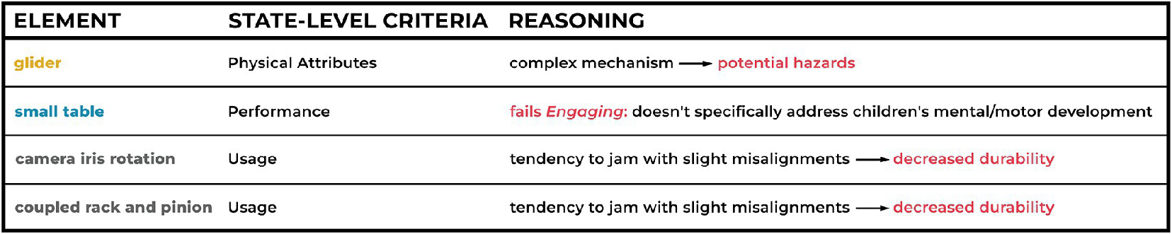
The product is decomposed into its constituent elements so that a first round of concept generation can be completed. Just as there are often multiple solutions to a single problem, there are often multiple mode-forms that can meet all of the modal criteria, i.e. the specifications and requirements. Similarly, there can be multiple transformation methods that transition between product modes while meeting all relevant criteria. Methods to aid with concept generation and brainstorming are prevalent within existing research (van Boeijen, Daalhuizen, & Zijlstra Reference van Boeijen, Daalhuizen and Zijlstra2020). Prior research in transforming products has also yielded multiple methods for generating possible transformation methods for a set of requirements (Singh et al. Reference Singh, Walther, Krager, Putnam, Koraishy, Wood and Jensen2007; Singh et al. Reference Singh, Skiles, Krager, Wood, Jensen and Sierakowski2009; Zhang et al. Reference Zhang, Cao, Peng, Tan, Liu and Zhang2022) using a set of four transformation principles and 20 transformation facilitators described in (Skiles et al. Reference Skiles, Singh, Krager, Seepersad, Wood and Jensen2006; Singh et al. Reference Singh, Skiles, Krager, Wood, Jensen and Sierakowski2009; Wang et al. Reference Wang, Kuhr, Kaufman, Crawford, Wood and Jensen2009; Haldaman & Parkinson Reference Haldaman and Parkinson2010; Kalimuthu et al. Reference Kalimuthu, Hayat, Elara and Wood2022). Three classes of criteria to be considered in the evaluation of the mode-forms and transformation methods (called state-level criteria) are presented by Literman et al. (Reference Literman, Cormier and Lewis2012): 1. Physical Attributes, 2. Performance, and 3. Usage.
3.2.2. STEP 2.2: Forming Adjacent Mode-Method-Mode Units
Following the generation of sets of possible mode-forms and transformation methods, mode- method -mode units are formed by linking adjacent modes through the use of a single transformation method. All possible combinations should be explored for each pair of adjacent modes using each possible transformation method. A method to guide the design of a two-mode product through the combination of two previously designed single-mode products (Kalyanasundaram & Lewis Reference Kalyanasundaram and Lewis2014) can be followed to aid in the formulation of the units. To reduce the number of total possible product concepts, the set of units must be pruned by evaluating the concepts against the overall requirements for the whole product.
3.2.3. STEP 2.3: Forming Compatible Concepts Through Unit Chaining
Mode- method -mode units are combined to form full design concepts by iteratively chaining multiple units together. Mode 1- method -mode 2 units are first chained with compatible mode 2- method -mode 3 units, i.e. mode 2–3 units that share a common form of mode 2 with a particular mode 1–2 unit. Feasible mode 1–3 chains should then be evaluated against the overall product requirements. For products with more than three modes, the process of chaining and evaluating can then be repeated to append additional modes to the growing chain.
3.2.4. STEP 2.4: Combining Similar Concepts
It is useful to evaluate the full-product concepts for uniqueness to inform a first round of redesigning. Groups of concepts that share all of the same mode-forms but different transformation methods are analyzed to determine if there are particularly effective ways in which product components are re-used across modes. These aspects of the designs are favored while redesigning to merge the similar concepts. In some cases, this may require the use of multiple transformation methods at one transformation point. While this redesign may improve the expected performance of the mode-forms by using the more effective design aspects, it will complicate the transformation, perhaps making it require more time, power, or tools. This tradeoff between mode-form performance and transformation complexity is balanced through an evaluation against the product requirements.
3.2.5. STEP 2.5: Evaluating Full Design Concepts
The remaining full-product chains can be evaluated using any of the existing methods from prior research in the area of conceptual down selection for products of any kind (Honkala et al. Reference Honkala, Hämäläinen and Salonen2007; Okudan & Tauhid Reference Okudan and Tauhid2008). Research in the conceptual analysis of reconfigurable products suggests the chosen concept selection method should allow “the performance of individual states … to be assessed as well as the impact of transitions on system performance” (Literman et al. Reference Literman, Cormier and Lewis2012). Regardless of the concept selection method, it is suggested that multiple, diverse (meaning different mode-forms and/or transformation methods across the concept chains) top concepts, rather than a single “best” concept, be selected to proceed.
3.2.6. STEP 2.6: Redesigning Based on Stakeholder Feedback
Due to the systematic linking and chaining relying on the compatibility of shared components across product modes, each of the top concepts is defined to a sufficient level of detail regarding the materials and geometry of the product such that they can be presented to external stakeholders for feedback on the product design. This feedback can uncover positive or negative aspects of the designs that may have otherwise been overlooked by the designer. The respective importance of either side of a tradeoff within the design from a stakeholder’s perspective is often difficult to predict. These trade-offs, while common for all product design, are often more prevalent in structurally transforming multi-mode products as the sharing of product components across modes to realize different functions induces additional couplings. The integration of transformations into the product design also results in an extra dimension to consider as the user interacts with the product not only in each of its modes but also during the transformations, especially if the transformations are human-powered. User experience during these interactions can be particularly difficult to understand without stakeholder feedback.
4. Case Study: Three-Mode Child Furniture Product
The University of Michigan and the nonprofit organization, Kids In Danger, collaborated to design a children’s furniture product that was intended to replace multiple products that have been recalled due to various safety concerns. The design of this new product followed the steps previously laid out in the high-level framework and therefore serves as a case study illustrating how the proposed framework can be applied to a real design problem. A set of tabular tools was developed throughout the design process to organize the information generated and evaluated in each step.
4.1. Stage 1: Problem Definition
Children’s furniture products are primarily designed to meet the needs of children of a specified age group. There are cases of recalled products across many of these age groups (KID 2022), indicating the need to design multiple products for each affected age group. Instead, the design team aimed to design a structurally transforming multi-mode product for multiple age groups as the system met Weaver, Wood, and Jensen’s (Reference Weaver, Wood and Jensen2008) second and third indicators: using similar materials across dissimilar configurations and a single product being more convenient than multiple.
4.1.1. STEP 1.1: Shared Requirement Definition
Existing products that aim to meet the need for safe furniture for children include cradles, bassinets, cribs, floor seats, bouncers, and high chairs. These products were compared to form a set of eleven shared requirements that all successful furniture products meet: Supportive, Stable, Strong, Durable, Non-Hazardous, Intuitive, Affordable, Portable, Washable, Engaging, and Size Accommodating.
4.1.2. STEP 1.2: External Factor Identification
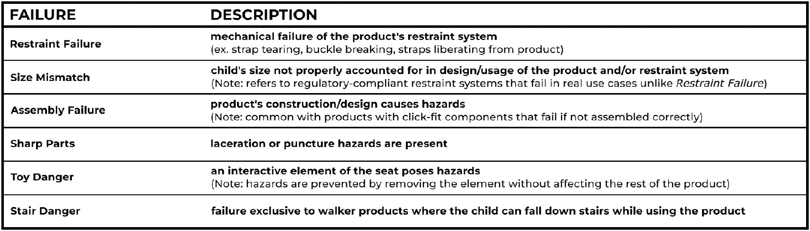
To better understand the need for safe furniture for children and specifically why and how existing products fail to meet this need, the designers analyzed 93 children’s furniture product recalls reported by the United States Consumer Product Safety Commission (CPSC) between 1977 and 2023 (CPSC.gov 2024). The type of hazards that led to the recall as well as the failure that caused the hazard were recorded as defined in Table 2 and correlated in Figure 3.
Six failure types identified in an analysis of children’s furniture product recalls in order of prevalence.
Failures, shown by each color-coded bubble, are the root cause of certain hazards (encapsulated within the bubbles) that result in a recalled product. The ordered size of the bubbles reflects the order of the impact of the underlying cause, with a larger bubble meaning a larger total number of product units being recalled. Any hazard with an asterisk next to it indicates that this hazard can lead to the death of the child using the product.
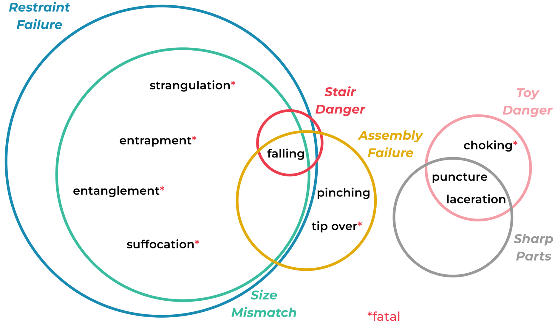
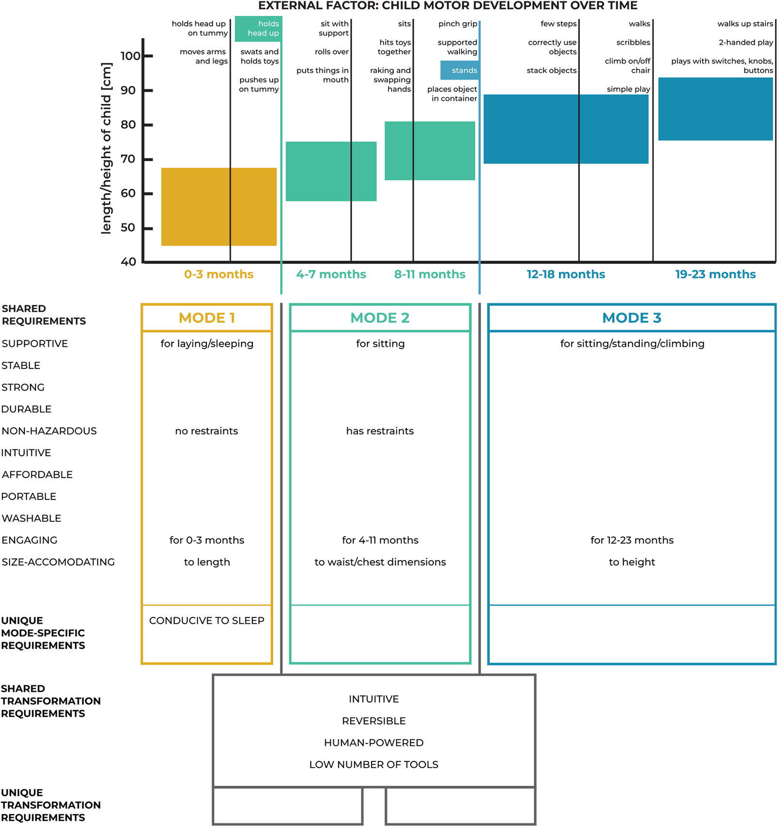
Figure 3 shows that there is not a one-to-one pairing between failure type and hazard, with a particular failure resulting in multiple hazards or one particular hazard resulting from multiple possible failure types. Designer attention was focused on Restraint Failure and Size Mismatch due to the frequency and severity of the danger the failures pose as supported by the large number of product units impacted by recalls due to these causes and the fact that the hazards that are a result of these failures can often be fatal (Figure 3). Additional research into safety standards and the marketing of children’s furniture revealed that since children’s furniture is designed in mind of a specific age range, an assumption is made as to the expected level of motor control for the child given the child’s age, likely contributing to the possibility of a Size Mismatch failure. The dependence between a child’s age, size, and motor ability was investigated to corroborate this hypothesis. The vertical overlap between the blocks in the length/height versus age plot at the top of Figure 4 shows that age alone is not a good predictor of child size. Additionally, as the plotted development milestones are only an estimate and can shift with respect to age for each child, age is, similarly, not a good indicator of motor ability. Therefore, the designers concluded the current system of designing children’s furniture to meet a specific age is flawed and can lead to unintentional hazards when the child’s motor control is more or less developed than expected as parts of the product’s design can result in falls, entrapments, suffocation and strangulations (kidsindanger.org 2018; CPSC.gov 2024). This analysis led to the identification of the product’s external factor to be not age, but the child’s motor development, particularly the set of notable motor milestones that can be easily identified by a child’s caretaker.
Tabular tool for organizing all product requirements across modes and transformation methods.
4.1.3. STEP 1.3: Mode Identification
Two motor development milestones were already used by the CPSC (ASTM Subcommittee F15.16 2020; ASTM Subcommittee F15.17 2022; ASTM Subcommittee F15.18 2022; ASTM Subcommittee F15.59 2022) to describe when certain children’s furniture is safe to be used: the ability to hold their own head up and the ability to stand. Therefore, three modes were defined by these two signal values (highlighted in Figure 4) such that these safety standards can be used to define the requirements and specifications of each mode: 1. before the child can hold their own head up, 2. when the child can hold their own head up but can not stand, and 3. when the child can stand.
4.1.4. STEP 1.4: Mode-Specific Requirement Definition
While the shared requirements of Supportive, Non -Hazardous, Engaging, and Adaptable were shared across the modes, the implementation was dependent on the child’s motor development stage in each mode. For example, in the first mode “Supportive” referred to supporting a baby lying down, while in the second mode, it referred to supporting a baby sitting up. All mode-specific requirement modifiers were organized in each mode column of Figure 4 and were aligned horizontally with the corresponding shared requirement from the full list along the left side of the figure. In addition to these requirements, a new unique mode-specific requirement emerged for mode 1: Conducive to Sleep.
4.1.5. STEP 1.5: Transformation Requirement Definition
To reduce the cost and complexity of use, the transformation methods were constrained to be Human-Powered without the use of additional actuators or sensors. As the transformations are only necessary once over a period of months based on the child’s development, the transformation methods had No Speed Requirements. Due to the commonality of sharing children’s products within and across families, the transformations needed to be Reversible and Intuitive using Few Tools or instructions. Both transformation points were defined by this same set of shared transformation requirements (Figure 4).
4.1.6. STEP 1.6: Quantitative Specification Definition
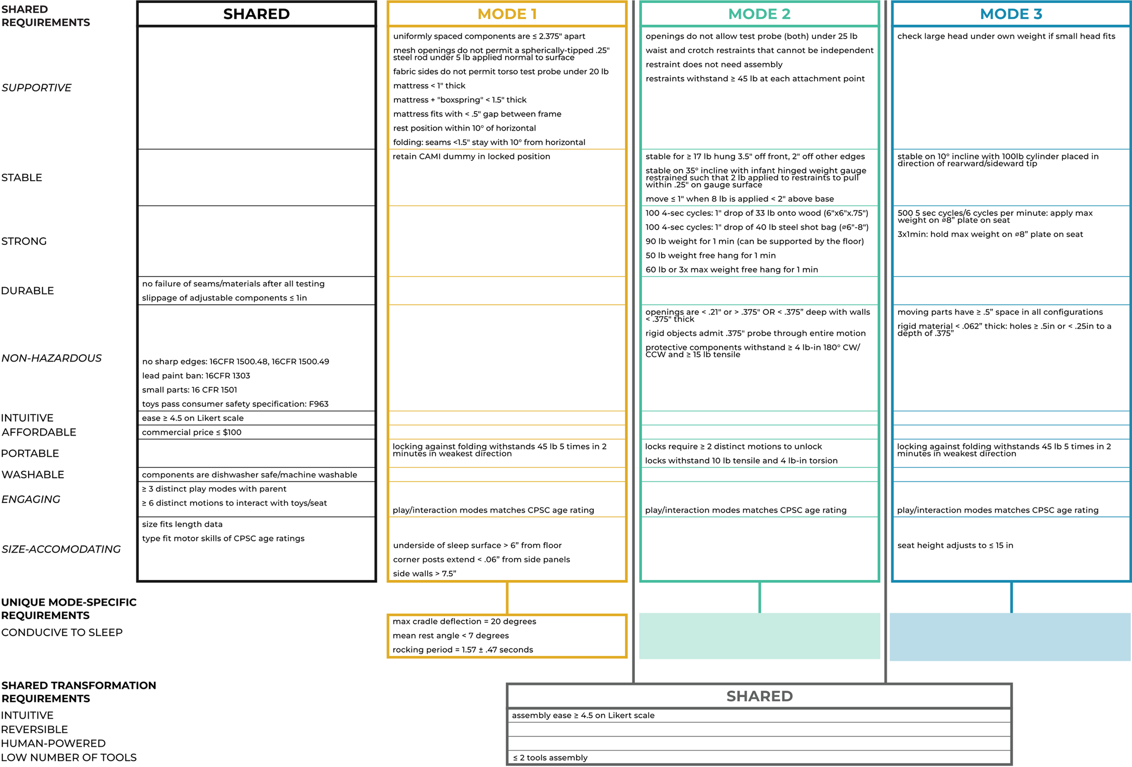
The vast majority of the specifications were written to represent the safety tests detailed in the ASTM standards (ASTM Subcommittee F15.16 2020; ASTM Subcommittee F15.17 2022; ASTM Subcommittee F15.18 2022; ASTM Subcommittee F15.59 2022) for similar children’s furniture in each mode. (As the exact form of each mode was not concretized until the completion of the Conceptual Design stage, the list of specifications was revisited after the selection of the final concept to ensure the product would meet all relevant CPSC regulations.) While many of the 16 total requirements were shared across the product’s three modes, only 15 of the 59 total specifications for the product are type 1: shared specifications, further supporting the need for multiple product modes due to the large number of differing specifications across the modes. The remaining 44 specifications are type 2 or 3 specifications associated with shared and modified shared requirements indicating that while the requirements of children’s furniture are similar across the modes, the types and target values for the specifications that ensure conformance to the requirements are significantly different in each mode. All specifications were organized in Figure 5 following a similar structure to Figure 4 such that all product requirements are listed along the left side and corresponding specifications are organized in modal and transformation columns.
Tabular tool for organizing all specifications. Italicized requirements had mode-specific modifications, requiring mode-specific specifications of type 2 or 3.
4.2. Stage 2: Conceptual Design
The next stage of the proposed framework was followed to decompose and systematically recompose product concepts to explore the large solution space for the three-mode children’s furniture product.
4.2.1. STEP 2.1: Element Generation and Evaluation
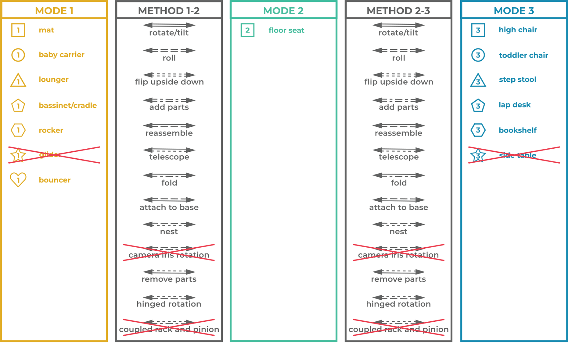
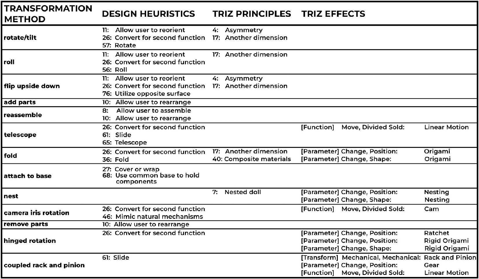
To prioritize product safety throughout the product design, the designers constrained each mode’s form to existing product types that have safety standards developed by the CPSC. An analysis of currently available single-mode, multi-mode, and multi-functional products for each mode’s corresponding developmental stage was completed to generate the list of mode-forms shown in Figure 6. The requirements for mode 2 are commonly met by a single type of children’s furniture: floor seats. Their prevalence in the market and the resulting familiarity among consumers should reduce the likelihood of potential hazards due to misuse. There is, however, a high incidence of product recalls on floor seats that become unsafe due to motor development mismatch with the child. This observation further supported the need for a product that can transform to meet a child’s changing needs to avoid these hazards. Both of the product’s transformation points: 1. from mode 1 to 2 and 2. from mode 2 to 3, share the same requirements and specifications. Thus, a single set of transformation methods was generated for both points through a combined analysis of Design Heuristics (Daly et al. Reference Daly, Yilmaz, Christian, Seifert and Gonzalez2012), TRIZ Principles (TIC 2024), and TRIZ Effects (TRIZ Innovation Centre 2024), as shown in Table 3. All generated elements are organized sequentially in Figure 6. State-level criteria were evaluated to guide the pruning of one mode 1-form, one mode 3-form, and two transformation methods at both transformation points (Table 4), therefore reducing the total number of possible full product concepts from an initial 7098 to 3630.
Tabular tool to organize mode-form and transformation method generation and evaluation for the children’s furniture product.
Transformation methods generated from an analysis of Design Heuristics, TRIZ Principles, and TRIZ Effects.
Reasoning for the elimination of generated elements according to state-level criteria.
4.2.2. STEP 2.2: Forming Adjacent Mode-Method-Mode Units
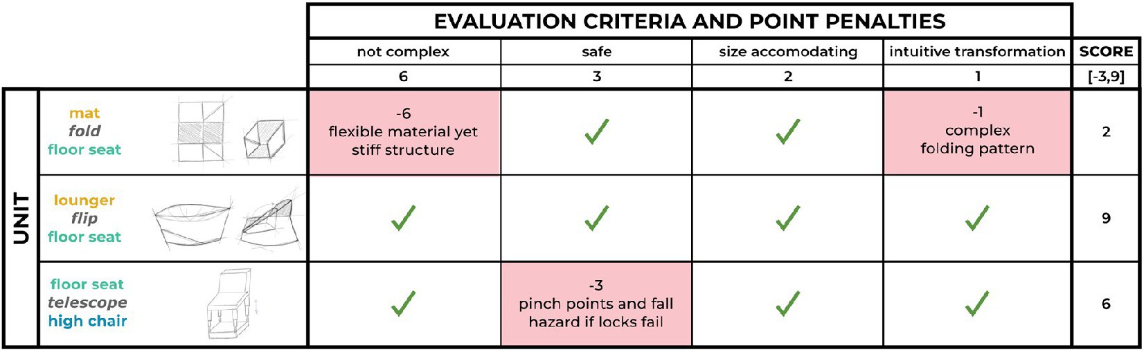
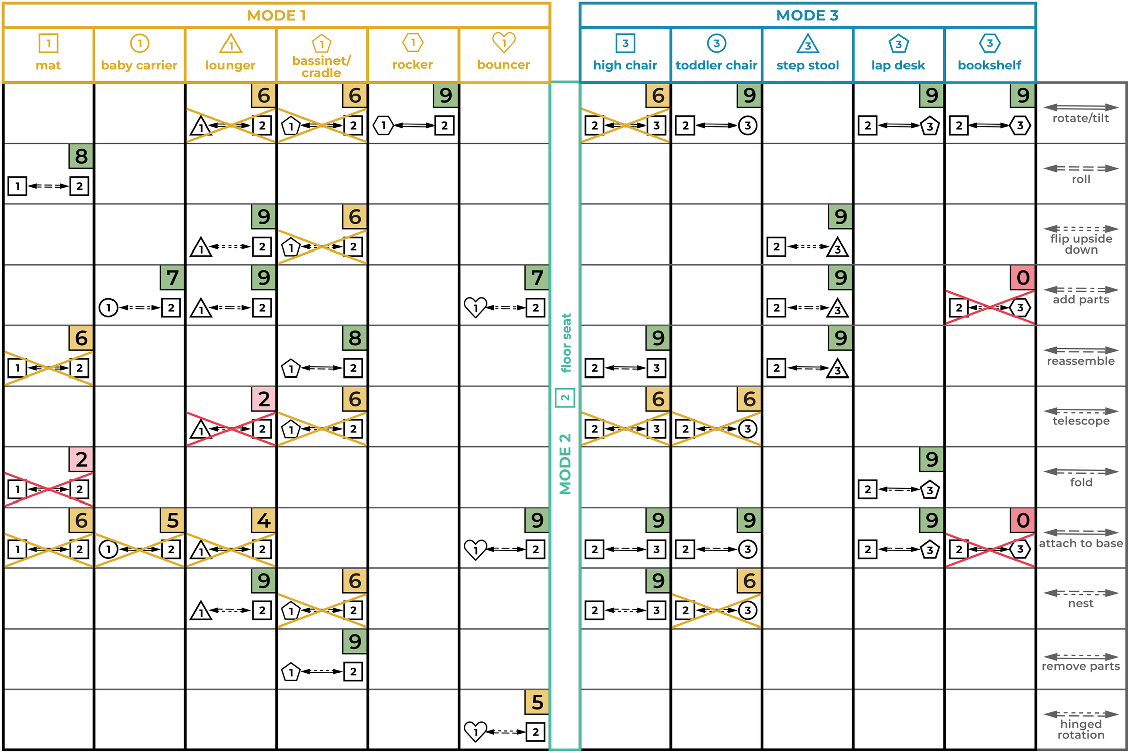
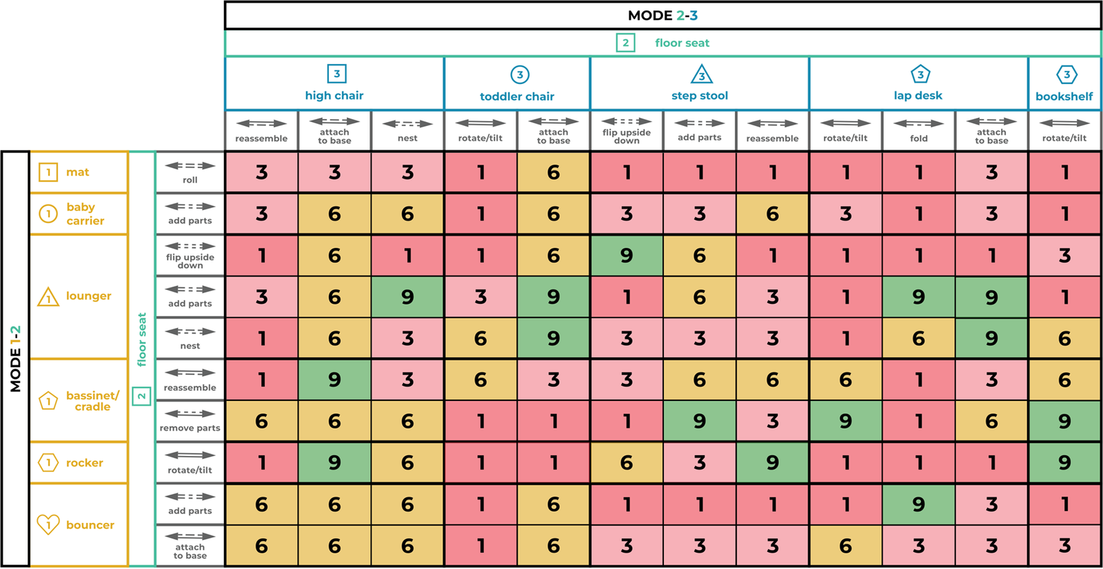
A table was formed to organize the linking of the six mode 1-forms and the five mode 3-forms (Figure 7) to the floor seat form of mode 2 via each of the 11 transformation methods. Rather than following the detailed method presented by Kalyanasundaram & Lewis (Reference Kalyanasundaram and Lewis2014), which was deemed too time-intensive given the large number of units to explore, low-fidelity concept sketches were drawn for each formed unit to quickly evaluate the feasibility with units that could not be conceptualized being deemed infeasible. Cases where one mode-form required a specific material or geometry that did not match that of an adjacent mode-form resulted in mostly infeasible units among the pairing regardless of transformation method. Similarly, a transformation method that was incompatible with the material or geometry of a single mode-form made all units with that pairing impossible regardless of the form of the other mode. To evaluate the feasible units, four main criteria were extracted from the most important shared product requirements and assigned a corresponding penalty to be subtracted from an initial score of 9, as exemplified in Table 5. Pruning units that received scores lower than 4 reduced the total number of possible units to 120 formed through the combination of 10 mode 1–2 units and 12 mode 2–3 units.
Examples of the mode-method-mode unit evaluation process used to populate the scores shown in Figure 7.
Tabular tool to organize the creation and evaluation of all mode 1- method -mode 2 and mode 2- method -mode 3 units. Cells are left empty for units that are not feasible.
4.2.3. STEP 2.3: Forming Compatible Concepts Through Unit Chaining
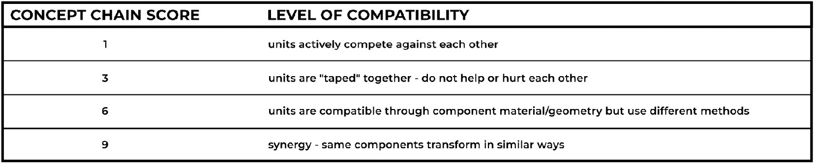
As there is only one mode-2 form, all remaining units were compatible and were linked together in every possible combination to form a set of mode 1- mode 3 chains as organized in Figure 8. To evaluate the feasibility of each chain within the set, the sketches created in the previous step for each unit were compared to determine whether the units have compatible product component material and geometry on a 1–3–6–9 basis, as shown in Table 6. This evaluation resulted in 15 chains that scored 9 (Figure 8) and advanced to the next step. The children’s furniture was defined as a three-mode product in the Problem Definition stage and thus needed only this one iteration of unit chaining.
Concept chain evaluation method (used in Figure 8) with scoring based on compatibility.
Tabular tool to organize the creation and evaluation of concept chains from remaining mode-method-mode units. Units are decomposed and organized along the table axes based on the elements of the units.
4.2.4. STEP 2.4: Combining Similar Concepts
This step was skipped due to the already manageable number of concepts remaining after the previous step. The decision was also supported by a lack of great opportunity to combine concepts as there were only two instances of concepts with the same mode-forms but different transformation methods.
4.2.5. STEP 2.5: Evaluating Full Design Concepts
The remaining 15 concepts were decomposed into their constituent elements and organized into a hierarchy, as shown in Figure 9, to evaluate diversity among the concepts. Most of the concepts (7 of 15) had the same mode 1 form: lounger, while there were a total of five different mode 3 forms represented at very similar frequencies with each appearing in two to four concepts. There were few trends between the transformation methods with a variety being represented across both points. There were equally few trends among the combinations of mode-forms and transformations with little evidence of specific mode-forms or methods being particularly synergistic together.
A decision matrix tool to organize the evaluation of the full product concept chains against the product requirements.
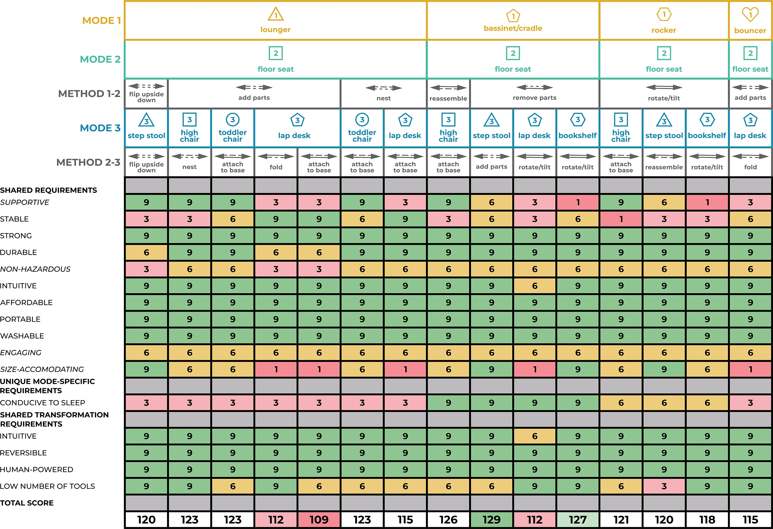
The 15 concepts were then evaluated against the set of 16 product requirements for the modes and transformation methods. Often concepts with the same mode-form or transformation method were scored the same for a particular requirement. To maintain conceptual diversity in the final step of the Conceptual Design stage, the top concept: bassinet/cradle where parts are removed to turn into a floor seat and then parts are added to turn into a step stool – was selected along with a lower scoring concept: bassinet where parts are removed to turn into a floor seat and then product rotates to turn into a lap desk – which meets the mode 1 specific requirement just as well as the top concept to proceed.
4.2.6. STEP 2.6: Redesigning Based on Stakeholder Feedback
A survey was created to present three concepts (the two selected in the previous step with the top concept split into two different chains: one starting as a bassinet and one starting as a cradle, as each allowed for very different component geometries) with sketches (shown in Figure 10) and a brief description to caregivers to ask them to rank the concepts based on how likely they would be to buy or use a product based on the concept and to provide their reasoning. The survey was sent to many different caregivers, including moms, dads, babysitters, and daycare workers (with and without a design background) to understand the effect the caregiving role may have on concept preference. A total of 19 responses were received and the reasonings for the rankings were collected and summarized in the tables in Figure 10. From the feedback, the concept of a cradle where parts are removed to turn into a floor seat and then parts are added to turn into a step stool received the highest net positive score and was thus selected as the final product concept to continue into the Embodiment Design stage.
Tabular tool for organizing the stakeholder feedback to inform selection and redesign of the children’s furniture product concept. The two concepts with a bassinet as mode 1 received net negative scores indicating the number and severity of the cons outweigh the pros for the concept. The concept starting with a cradle in mode 1 received a net positive score primarily because no cons were identified as intrinsic to the concept.

4.3. The Final Design
Balancing the advantages and disadvantages of the transformations between the product’s multiple modes continued as a major focus throughout the Embodiment Design stage as the chosen design was finalized. As such, additional design iterations were needed to ensure the product’s requirements and specifications were met. Three strategies were used to address all of the 59 product specifications (in order of increasing design complexity):
-
1. using industry-standard components that meet regulations
-
2. instating dimensional constraints on product components
-
3. analyzing a first principles physics model
In total, 19 first principles models were created to determine the values of 17 variables through an iterative human-in-the-loop optimization-like technique that allowed the designer to balance when a design variable was pushed in opposite directions by multiple specifications. Figure 11 shows the final design, which uses the final design variable values, as a CAD model and a physical prototype that was tested against all specifications to confirm mode and transformation feasibility and intuitiveness.
CAD model and physical prototype of children’s furniture product final concept.
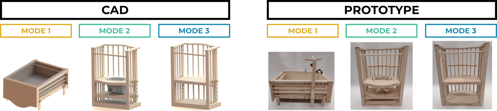
The final children’s furniture design featured a frame that was reused in all three modes in two different orientations. The dimensions of the frame were chosen carefully via first principles models to meet conflicting specifications related to the rocking dynamics of the cradle in the horizontal orientation and the tipping stability of the floor seat and step stool in the vertical orientation. To meet product specifications, including strict children’s safety regulations, multiple transformation methods were needed within each mode transition to avoid introducing hazards during real product use. The frame featured a peg-in-hole system to facilitate these transitions and offer additional adjustability. To transform from mode 1 to mode 2, the cradle mattress and support were removed, one end of the cradle was reassembled lower in the frame to act as an adjustable height footrest, and a seat was added into the frame to pass the strict safety regulations regarding floor seat restraints. While the added seat components reduced the space-saving benefit of the structurally transforming multi-mode product, other designs that reused one of the components from the cradle introduced unacceptable safety hazards in one or both modes. To transform from mode 2 to mode 3, the seat component was removed, and the end of the cradle/footrest component was reused as the step of the step stool. The height of the step was adjusted throughout the peg-in-hole system to match the child’s height as the child grew. A back support component across the top of the frame was originally designed to be added during the mode 2–3 transition. This, however, introduced the possibility of child fall hazards if this step of the transformation was unsuccessful, reducing overall product safety. As such, the design was altered such that the component was permanently installed in the frame without impacting the other two modes.
5. Discussion
The overall success of the proposed framework is determined by the success of the products it is used to design as well as the extent to which the framework’s four goals, as stated in Section 1, are met. This section is divided into two sections to address both topics.
5.1. Discussion of the Case Study Product Concept
The product concept and the manufactured prototype were evaluated both quantitatively, through a set of tests based on the defined specifications, and qualitatively, by project stakeholders. As the majority of the product’s 59 defined specifications were based on the ASTM standards for children’s furniture safety, the tests performed to evaluate the product prototype were designed to match the tests described in the standards (ASTM Subcommittee F15.16 2020; ASTM Subcommittee F15.17 2022; ASTM Subcommittee F15.18 2022; ASTM Subcommittee F15.59 2022). Widely, the prototype performed as expected throughout the testing, meeting or exceeding the specifications. The few cases where a test failed were due to issues with precision within the manufacturing of the prototype. The assembly of the prototype’s cradle mattress and mattress support higher above the ground than in the CAD design caused the cradle’s rocking period to be 24% longer than the specification’s upper limit: 2.52 seconds compared to 1.57 ± .47 seconds. Issues with inconsistent radii and roundness of the dowels used to manufacture the pegs for the peg-in-hole system caused the maximum locking force to be 30% lower than the specification nominal value: 7 pounds compared to 10 pounds. These precision issues with the mattress height and the peg radii could be resolved with higher-quality materials and higher-fidelity manufacturing techniques. Alternatively, these issues present opportunities for redesign to avoid the need for these higher-cost materials or processes.
The product design was also evaluated qualitatively when the prototype was presented to potential stakeholders, including project partners at KID and the CPSC as well as members of the public, at a Mechanical Engineering Design Expo at the University of Michigan. The project partners were pleased with the product concept, praising its intuitive and user-friendly design that emphasized safety through the minimization of potential hazards and failure points. Members of the public who attended the Expo were impressed by the variety of functions that the multiple modes allowed while remaining a mechanically simple design. Parents and caregivers who attended the Expo reacted positively to other product details like easily removable and machine-washable fabric components in the first two modes and height adjustability in the third mode. Overall, the product concept designed using the developed framework was successful in addressing the identified problem with existing children’s furniture and meeting the expectations of project partners and outside stakeholders while requiring only minor redesigns following final evaluations.
5.2. Discussion of the Framework
The extent to which the framework for structurally transforming multi-mode products addressed each of the four goals stated in Section 1 is illustrated through a reflection of the case study.
5.2.1. GOAL 1: To Help Identify the Possibility/Need for a Structurally Transforming Multi-Mode Product
As stated in Section 4.1, the case study design problem met the second and third of Weaver, Wood, and Jensen’s (Reference Weaver, Wood and Jensen2008) indicators for the possibility for a structurally transforming multi-mode product. Reflecting on the concepts generated and evaluated throughout the Conceptual Design stage, there is an apparent correlation between the third indicator and which concept units or chains are likely to be successful in meeting the product requirements and specifications. Particularly, the mode-method-mode units that included mode forms with higher degrees of similarity between materials were more likely to score highly in the evaluation in Figure 7 of Section 4.2 STEP 2.2. This was once again true in both STEPS 2.3 and 2.5, suggesting that keeping these initial indicators in mind throughout the design process can additionally help to guide effective downselection of product concepts.
5.2.2. GOAL 2: To Understand all Constraints on the Design
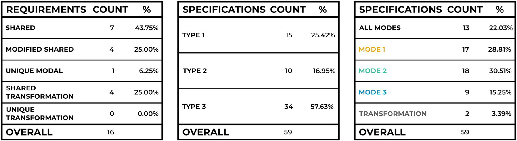
The Problem Definition stage of the framework was developed to guide the designer’s exploration of the design problem to understand the constraints that define the product solution. An analysis of the case study product’s requirements and specifications provides insights into the nature and extent of constraints that could be expected for a structurally transforming multi-mode product. Tables 7a and 7b show that while the majority (68.75%) of product requirements are shared without any modifications, the majority (57.63%) of product specifications are type 3: different form. While this seems contradictory, this evidence supports the need and possibility for a structurally transforming multi-mode product. The difference between product specifications drives the need for multiple specialized modes, while the similarity within the product requirements supports the argument that a single transforming product can be designed to solve the design problem rather than requiring multiple separate products. Furthermore, the modes of the case study product were under similar levels of constraint as there were similar numbers of specifications that applied across all of the modes and that applied to each mode individually (Table 7c). Mode 3 has fewer specifications than either of the other modes primarily because there was not a CPSC safety standard for the designers to follow at the time.
Analysis of requirements and specifications for the case study product.
5.2.3. GOAL 3: To Guide the Exploration of the Large Solution Space
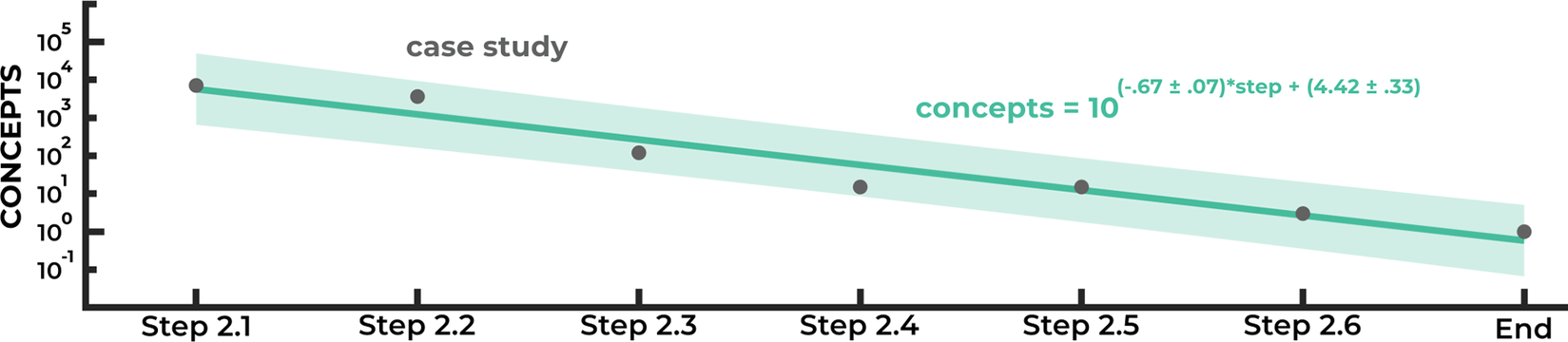
The systematic process outlined in the six steps of the Conceptual Design stage encourages the generation of a wide solution space during the first step (2.1). The increased cost of exploring a large number of concepts is then avoided through subsequent evaluation and downselection steps to cull the solution space. In the case study, a total of 7098 concepts were originally possible following the element generation of STEP 2.1. By STEP 2.5, only 15 detailed full-product concepts were evaluated at a high level of detail, accounting for only .21% of initial concepts. An analysis of the number of possible concepts at each step of the Conceptual Design stage, as shown in Figure 12, reveals that the framework’s systematic process exhibits linear convergence to the case study’s final product concept. This supports the assertion that the framework effectively guides the designers to navigate a large number of possible concepts through systematic information consolidation.
Downselection during the Conceptual Design stage exhibits linear convergence. The R2 value of the linear fit for the case study concept data is .943, indicating a strong linear fit to the semi-log plot.
5.2.4. GOAL 4: To Balance the Advantages and Disadvantages of Transformations Between Multiple Modes
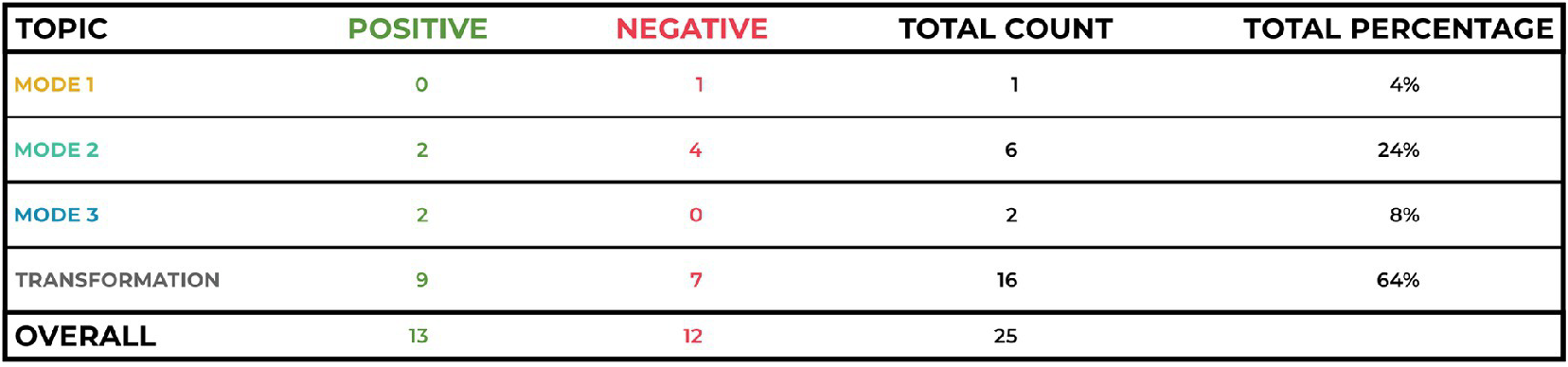
The importance of the transformations between modes is emphasized in both the Problem Definition and Conceptual Design stages. First, defining requirements and specifications for each of the product’s transformations ensures that the designer will regard the product’s transformation methods as integrated components of the product concept with their own criteria rather than an afterthought in favor of focusing on the design of the modes. The integration of the transformation methods is affirmed through the process of chaining together mode-form elements with transformation method elements. Concept units and chains with the same mode forms but different transformations are treated as unique units to be evaluated separately, allowing for the interaction between the modes and transformation methods to be examined and compared during concept evaluation. The feedback received from stakeholders during STEP 2.6 serves as strong evidence that the transformation methods are also important factors in user experience and perception of design concepts. As shown in Table 8, the majority of the feedback (64%) refers to product transformations, identifying both positive and negative aspects of the designs at nearly equal frequency.
Analysis of stakeholder feedback from case study STEP 2.6.
5.2.5. Extending the Framework to Nonlinear Products
The methods and tabular tools presented in the case study utilize the sequential ordering of the product’s modes. This suggests a limit to the framework in its current form to apply to only linear structurally transforming multi-mode products. The framework can be extended to apply more generally to allow nonlinear products through adjustments to the methods in both stages.
Within the Problem Definition stage, the Mode Identification step can be altered to use the identified external factor signal values in combination with expected user interactions to define a directed network where the nodes are the product’s modes and the edges are the transformations (Zhou et al. Reference Zhou, Cui, Hu, Zhang, Yang, Liu, Wang, Li and Sun2020). A similar modeling approach is described by Siddiqi & de Weck (Reference Siddiqi and de Weck2008), where reconfigurable products are modeled as a directed network of operation and reconfiguration states.
Regardless of the modeling method, within the Conceptual Design stage, the methods of generating and linking the possible mode-forms and methods to form mode-method-mode units can still be used to form possible connections between every edge’s end-nodes (each edge connects its two end-nodes). Similarly, the chaining methods described to identify compatible units via shared forms of a common mode to build the product concept chains can be used to build the modal network. Units can only form a hub (a node connected to many other nodes) if all units connecting at the hub are compatible by having the same shared mode-form at the hub node. Due to this high level of restriction, it would be most efficient to start here to form the product concept network. In the case of loops (cycles of nodes that connect a node back to itself) within the network, the final chaining iteration that closes a loop will have two compatibility constraints as both end nodes of the final edge will need to have a shared form with both ends of the partially constructed loop. Existing methods to traverse graphs (Zhou et al. Reference Zhou, Cui, Hu, Zhang, Yang, Liu, Wang, Li and Sun2020) can be used to efficiently navigate the modal network through unit chaining to build the full product concept network which can be evaluated through the same methods as a linear product.
5.2.6. Future Validation Work
The case study presented in the paper demonstrates the framework’s applicability to complex, linear, structurally transforming multi-mode products within the consumer products industry. Additional case studies can be done to evaluate the framework’s efficacy across a variety of domains including, but not limited to, aerospace, automotive, and medical device. These case studies should include both linear and nonlinear products, products with few and many modes, and products with human- and mechatronically-controlled transformations. Further validation of the framework can be completed through the development of a single-blind study that asks designers to use a variety of design processes, including this one, to design a structurally transforming multi-mode product in a design jam setting. Evaluation of the success of each design process used could be based on metrics including the time needed to complete the product design, designer satisfaction/frustration through the form of a survey, stakeholder satisfaction with the final product design through the form of a survey, and other project-specific success metrics and indicators. These studies would further strengthen the framework proposed in this paper.
6. Conclusion
Structurally transforming multi-mode products realize a wider variety of functions across their modes than non-reconfigurable multi-mode products, maintain higher ease of use compared to modular multi-mode products, and are more efficient than multiple alternative single-mode products. To accomplish all of these benefits, structurally transforming multi-mode products capitalize on physical transformations and reused structural components. While these aspects have distinct advantages over the other products, they also present new, previously unaddressed challenges during two stages of the design process: 1. Problem Definition and 2. Conceptual Design.
The framework proposed in this paper aims to systematically, cohesively, and comprehensively address these design challenges through the identification of the distinct steps needed to navigate both stages. Following the identification of the need and opportunity for a structurally transforming multi-mode product, the Problem Definition stage aims to define the product’s modes and the set of criteria that constrains the form of both the modes and transformation methods. The Conceptual Design stage involves first comprehensively exploring the large solution space to independently generate all possible forms of each of the product’s modes and transformation methods, followed by a systematic process of combining the generated concept elements, utilizing the ordering of modes that has been defined during the Problem Definition stage. Multiple rounds of evaluations of possible product concepts during the concept development process allow the designer to balance the advantages and disadvantages of transformations between multiple modes.
The methods included in the framework successfully guided the design of a three-mode structurally transforming children’s furniture product, demonstrating the framework’s efficacy in facilitating better, more effective design of structurally transforming multi-mode products.
Acknowledgments
This research receives no specific grant from any funding agency, commercial or not-for-profit sectors.


 Open access