

Introduction
Mesocrystals, the ordered nanocrystal superstructures, with intriguing properties and versatile functionalities, have been the focus in the fields of solid-state chemistry and condensed matter physics over the past decades due to their exciting potential for cutting-edge researches and innovative applications.[ Reference Cölfen and Antonietti: 1 , Reference Kulak, Iddon, Li, Armes, Cölfen, Paris, Wilson and Meldrum 2 ] In contrast to randomly distributed nanocrystal and single-crystal systems, mesocrystal is a collective system composed of individual functional nanocrystals showing the same crystallographic connectivity, as illustrated in Fig. 1. The mesocrystal itself with interspersed environment forms a functional system, mesocrystal-embedded system, offering fruitful properties and possibilities to impact the modern technology for catalytic, electronic, optical, magnetic, drug delivery, and reaction precursor applications.[ Reference Ma, Teo, Mei, Zhong, Li, Wang, Duan, Lian and Zheng 3 , Reference Fang, Ding and Gleiter 4 ] Due to their structural nature, the mesoscopically well-ordered crystals can exhibit unique properties and functionalities that cannot be seen in the parent bulk materials. Typical examples of mesocrystals can be found in various materials as diverse as metal oxides,[ Reference Liu, Wen, Wu, Gao, Chen, Zhu and Chu 5 – Reference Hu, Gong, Zhang and Yu 9 ] II/IV semiconductors,[ Reference Ryan, Mastroianni, Stancil, Liu and Alivisatos 10 , Reference Kang, Lai, Peng, Shyue and Chou 11 ] complex oxides,[ Reference Zhou, Wang and Xu 12 , Reference Gong, Qian, Ma and Zhu 13 ] fluorides,[ Reference Zhang, Chen, Zhou and Li 14 ] phosphates,[ Reference Yang, Chen and Lin 15 ] organic molecular systems,[ Reference Wohlrab, Pinna, Antonietti and Cölfen: 16 , Reference Zhang, Paspal, Suryanarayanan and Grant 17 ] etc.
Mesocrystal and functional mesocrystal-embedded oxide systems.

To date, considerable efforts have been made to develop synthesis mechanisms, to acquire new members of the mesocrystal family, and to tailor their tantalizing functionalities. Conventional strategies for mesocrystal syntheses are usually attained by chemical-solution-based methods and subsequent controlled growth for highly ordered crystalline structure. However, the progresses in oxide thin-film growth and corresponding innovation have eased the fabrication of high-quality crystalline materials composed of different oxide ingredients. With the advancement of thin-film growth techniques, the production of abundant combination and non-equilibrium creation of numerous mesocrystals can be achieved, allowing the properties of mesocrystals to be tailored by multiple controlling factors as well as by the epitaxy to the dispersed media, leading to the flurry of mesocrystal-embedded oxide systems. Besides, a number of fascinating phenomena as well as promising explorations of novel mesocrystals based on complex oxides have been carried out, lighting up the opportunity toward multifunctional mesocrystal-embedded oxide systems.
In this perspective article, we highlight the development and importance of mesocrystal-embedded oxide systems. Throughout this article we will describe the functionalities and properties presented by the mesocrystal, the dispersed matrix materials, and the whole entirety of mesocrystal-embedded system, with a special attention to inspect the promising features offered by functional systems. We will go through a wide spectrum of prototypical examples of mesocrystal-embedded materials within each functional subgroup and delve into the interactions between the mesocrystal and dispersed matrix. In the end, an overlook is provided to the future of mesocrystal-embedded oxide systems with the special attention given to possible fields and directions for new technology, by which we hope to inspire more spark on ultimate potential triggered by mesocrystal-embedded systems.
Mesocrystals in oxide matrices
To tune inherent functionalities of a mesocrystal, orientation control on mesocrystal is one of the effective methods. For example, Liao et al. have suggested that the morphology and magnetic anisotropy of CoFe2O4 (CFO) mesocrystal-embedded in BiFeO3 (BFO) matrix can be altered by merely varying the crystallographic orientations of CFO mesocrystal. As the schematic shown in Fig. 2(a), the CFO mesocrystal has been found to present (110), (001), and (111) preferred crystallographic orientations on DyScO3 (DSO), SrTiO3 (STO), and NdGaO3 (NGO) substrates, respectively.[ Reference Liao, Tsai, Liu, Liang, Yang, Lin, Lai and Chu 18 ] According to the Winterbottom construction, different crystallographic orientations have different equilibrium morphology determined by the energy competition between interface and surface of the CFO mesocrystal and selected substrates. CFO is a well-known ferrimagnetic spinel with the lowest surface energy of {111} facets, resulting in the equilibrium shape of an octahedron.[ Reference Zheng, Zhan, Zavaliche, Sherburne, Straub, Cruz, Chen, Dahmen and Ramesh 19 , Reference Liu, Liang, Chu, Zheng and Ramesh 20 ] Hence, for (001)-oriented CFO mesocrystal grown on the (001)-oriented STO substrate, the octahedron stands with four facets and emerges as a pyramid-like crystal on the surface. For (110)- and (111)-oriented CFO mesocrystals grown on (001)pc-oriented DSO and NGO substrates, the octahedrons rotate 90° and 54.7° with the same facets following the similar logic, resulting in a roof-like shape and a triangle-platform shape, respectively. The images obtained by atomic force microscopy (AFM) in the insets of Figs. 2(b)–2(d) confirm the topography of nanocrystals on the relative substrates. Interestingly, these CFO mesocrystals have crystal lattice constants close to bulk CFO, indicating they are almost strain free. It also implies that the interface energy plays a dominant role in modulating the morphologies and crystallographic orientations of a mesocrystal while keeping the same crystallographic orientation of the neighboring matrix.
CFO–BFO functional oxide system. (a) Schematic of the lowest energy surfaces of the CFO mesocrystal embedding in BFO matrix. (b)–(d) Magnetic hysteresis loops of CFO–BFO functional oxide system with different IP directions (upper panels) and loops with respect to IP and OOP directions (lower panels) of samples grown on DSO, STO, and NGO substrates, respectively. Reprinted with permission from Ref. Reference Liao, Tsai, Liu, Liang, Yang, Lin, Lai and Chu18. © (2011) American Chemical Society.

Simultaneously, the magnetic anisotropy of the CFO mesocrystal was further revealed, as shown in Figs. 2(b)–2(d). Since the contributions from the magnetocrystalline and magnetostriction anisotropies should be very small due to the features of cubic symmetry and strain relaxation of CFO, the shape anisotropy dominates the magnetic behavior in this system. For (001)-oriented CFO mesocrystal grown on the STO substrate, the hysteresis loops measured along the in-plane (IP) directions with different azimuthal angles and the out-of-plane (OOP) direction show the magnetic easy axis is along the OOP direction, the long axis of the nanocrystals. For the (110)-oriented CFO mesocrystal grown on the DSO substrate, the magnetic easy axis is set to be in the IP direction corresponding to the long-axis of its nanocrystals. For the (111)-oriented CFO mesocrystal, no obvious magnetic anisotropy is observed because the size of these triangular nanocrystals is very close to the film thickness.
In addition, control of the strain state of mesocrystals is another approach to tune the corresponding functionalities. The matrix material in a mesocrystal system exhibits a strong influence on the strain state of neighboring nanocrystals.[ Reference Liu, Liu, Tsai, Liao, Chen, Lin, Lai, Hsieh, Li, Chen, He and Chu 21 ] Figures 3(a)–3(c) illustrate the typical feature of a mesocrystal consisting of spinel CFO nanocrystals embedded in four different perovskite matrices grown on (001)-oriented STO substrates. Here, the STO substrate was used to control the crystallographic orientation without an obvious clamping effect on the mesocrystal, and thus the variations in the lattice and magnetic properties of the mesocrystal were principally dominated by the physical interaction between the mesocrystal and matrix materials. The result from Raman spectroscopy shown in Fig. 3(d) clearly reveals a blue shift of the CFO A 1g phonon mode, indicating that the CFO mesocrystal suffers a gradual increase of compressive strain along the OOP direction while varying the matrix from BFO, PbTiO3 (PTO), STO to SrRuO3 (SRO). Similar result was confirmed by the x-ray reciprocal space maps, in which the corresponding OOP/IP strains of CFO can then be obtained as −0.1%/0.05%, −0.24%/0.1%, −0.67%/0.41%, and −1.2%/1% with BFO, PTO, STO, and SRO, respectively. It is noteworthy that CFO shows a strong magnetostrictive effect with λ 001 ~ −350 × 10−6.[ Reference Zheng, Wang, Lofland, Ma, Mohaddes-Ardabili, Zhao, Salamanca-Riba, Shinde, Ogale, Bai, Viehland, Jia, Schlom, Wuttig, Roytburd and Ramesh 22 ] A more square and broadened shape presented in the OOP hysteresis loops [Fig. 3(e)] together with a more tilting and narrower shape in the IP hysteresis loops [Fig. 3(f)] suggests a rotation of the magnetic easy axis toward the OOP direction while varying the matrices in a sequence of BFO, PTO, STO to SRO. Such a variation can be directly correlated to the enlarged compressive strain along the c-axis of the mesocrystals, showing a good agreement with the x-ray diffraction (XRD) and Raman results. Surprisingly, the factor to determine the strain state of CFO mesocrystal is independent of the lattice mismatch between the matrix and mesocrystal. For instance, CFO has a lattice mismatch of 5.6% and 6.3% with BFO and SRO, respectively. However, the CFO mesocrystal is almost strain-relaxed in the BFO matrix but has a large OOP compressive strain (~ −1.2%) in the SRO matrix. Namely, even though there is the similar lattice mismatch between the mesocrystal and the surrounding matrix, the strain state of CFO can be significantly different. Liu et al. proposed that the mechanism to determine the magnitude of interfacial coupling between mesocrystal and matrix should be dominated by a basic physic parameter, the bonding strength. More intuitively, the bonding strength can be directly correlated to several common properties such as the melting point and stiffness. The correlation clearly points out that the strain state and magnetic anisotropy of the CFO mesocrystal increases with the melting point and the Young's modulus of the perovskite matrices. Since the matrix with larger bonding strength also possesses stronger atomic linkage and larger stiffness, and thus such characteristics can have a strong influence on the adjoining atoms of the CFO mesocrystal through an interfacial structural coupling.
(a) The schematic illustration of a self-assembled spinel CFO mesocrystal embedded in structure-coupled matrices. (b) The AFM image of such functional oxide systems. (c) The scheme of modulating the strain state of the CFO mesocrystal by varying the perovskite matrix. Raman spectra obtained from CFO mesocrystal embedded in various structure-coupled matrices (d) and corresponding hysteresis loops measured by applying the magnetic field along (e) OOP and (f) IP directions. Reprinted with permission from Ref. Reference Liu, Liu, Tsai, Liao, Chen, Lin, Lai, Hsieh, Li, Chen, He and Chu21. © (2015) American Association for the Advancement of Science.

Compared with conventional chemical approaches, the mesocrystal fabricated by self-assembled thin-film process can further provide the control of functionalities by applying external stimuli such as electric field, magnetic field, or light. In the case of CFO mesocrystal-embedded in SRO matrix reported by Liu et al., the SRO matrix inherently shows a large photostrictive effect, an expansion of lattice under illumination.[ Reference Liu, Chen, He, Liang, Chen, Chien, Hsieh, Lin, Arenholz, Luo, Chueh, Chen and Chu 23 ] From the investigation of ultrafast XRD, SRO exhibits a large photon-induced lattice expansion of 0.5%–1.5% under the laser fluence of 3–15 mJ/cm2[ Reference Bojahr, Schick, Maerten, Herzog, Vrejoiu, von Korff Schmising, Milne, Johnson and Bargheer 24 – Reference Korff Schmising, Harpoeth, Zhavoronkov, Ansari, Aku-Leh, Woerner, Elsaesser, Bargheer, Schmidbauer, Vrejoiu, Hesse and Alexe 26 ], implying that the compressive strain of CFO (~1.2% in SRO matrix) could be fully relaxed under a threshold of laser fluence. This concept was proven by a combination of the magneto-optic Kerr effect (MOKE) measurement and magnetic force microscopy (MFM). From the MOKE measurement, the change of magnetic moment of the CFO mesocrystal enlarges with the laser fluence. The irreversible phenomenon of the change in magnetic moment above the threshold fluence indicated a demagnetized state of the CFO mesocrystal, which was evidenced by the MFM measurement. As shown in Figs. 4(a)–4(c), a large portion (~78.8%) of the MFM image shows the bright contrast before the illumination, indicating the CFO mesocrystal is mostly magnetized downward along the OOP direction. After illuminating the sample, the coverage of the bright area becomes ~50.5% of the total area in the MFM image, indicating that the ratio of the downward and upward magnetized CFO nanopillars changes along with the light illumination. The scenario in Figs. 4(d)–4(f) clearly illustrates the variation of magnetization under the laser illumination, by which a nearly isotropic magnetization with non-preferential magnetic direction could be obtained, allowing the CFO magnetic domains to be freely redistributed. When the light is removed, the compressive strain of CFO mesocrystal returns, which leads to an increase of the magnetization opposite to the initial direction for the minimization of local magnetostatic energy.
CFO–SRO functional oxide system. (a) AFM topology and (b) MFM image at the same area of a CFO–SRO sample magnetized by applying a large OOP magnetic field before being illuminated. (c) MFM image at the same area after being illuminated. The red circles in (b) are the CFO nanopillars in (a) with downward magnetization, while half of these CFO pillars flipped upward in (c) are presented in yellow circles, suggesting a “liberation” in magnetization during illumination. (d)–(f) Schematic illustrations of the process of magnetic domain flipping during the illumination by ultrafast Ti:sapphire laser pulses. (d) Application of a large OOP magnetic field to magnetize all CFO nanopillars downward. (e) Illumination of light on the sample expands the lattice of SRO matrix and releases the vertical compressive strain of CFO mesocrystal. (f) Removal of light results in the magnetization of the CFO mesocrystal to become either parallel or antiparallel to the magnetic field direction for the energetically preferred state. Reprinted with permission from Ref. Reference Liu, Chen, He, Liang, Chen, Chien, Hsieh, Lin, Arenholz, Luo, Chueh, Chen and Chu23. © (2012) American Chemical Society.

Through the aforementioned three examples of the mesocrystal-embedded systems, one can clearly tell the potential to tailor the intrinsic properties of functional mesocrystals via the matrices. The study on the orientation control of CFO mesocrystal provides the possibilities of modulating magnetic anisotropy of a mesocrystal via the design of interface energy among the system. The work of various matrices embedded with CFO mesocrystal nicely demonstrated the matrix materials in mesocrystal systems can behave as a crucial role to tailor the functionalities of mesocrystals, which offers additional tunability that has never been achieved in traditional systems obtained from chemical processes. Furthermore, the SRO matrix embedded with CFO mesocrystal demonstrated the tunability of novel functionalities via external stimuli employed on the mesocrystal-embedded systems. More examples that wrap up the modulation and control of functional mesocrystals could be found in other systems as well.[ Reference Zavaliche, Zhao, Zheng, Straub, Cruz, Yang, Hao and Ramesh 27 ]
Multifuncationality modulated via an embedment of mesocrystals
While most studies hitherto have addressed the advanced functionalities and potential applications of mesocrystals, the attention has rarely been paid on new possibilities triggered by the elegant combination of mesocrystals and functional matrices. In order to further explore intriguing properties and modulation of functionalities of matrix materials driven or assisted by mesocrystals, various self-assembled mesocrystal-embedded oxide systems are reviewed in the following paragraphs.
An example on the mesocrystal-embedded system composed of semiconductor wurzite ZnO matrix and metallic perovskite SRO mesocrystal was demonstrated to investigate the metal–insulator transition and its photoresponse at room temperature.[ Reference Chang, Liu, Tra, Chen, Wei, Tzeng, Zhu, Kuo, Hsieh, Lin, Zhan, Luo, Lin, He, Wu and Chu 28 ] This system took the advantage of high interface-to-volume ratio in the self-assembled heteroepitaxy to create multiple junction interfaces for the enhancement of charge interaction. Figure 5(a) shows the schematic of SRO–ZnO mesocrystal-embedded system, while the results of the electron transport measurements and conductive atomic force microscopy (C-AFM) are shown in Fig. 5(b). The average spacing between the nanopillars decreases in each step of the development until they are too close to each other [volume of SRO (V SRO) = 75%]. The resistivity (ρ) of the SRO–ZnO system with different V SRO compared with those of pure SRO and ZnO films as a function of temperature is presented in the bottom-left panel of Fig. 5(b). A significant change in the electron transport behavior of SRO–ZnO mesocrystal system with respect to the interface-to-volume ratio is observed. By bringing SRO and ZnO together, the mesocrystal-embedded system shows a resistivity of 1–4 orders of magnitude lower than that of pure ZnO film, suggesting that the conductivity of SRO–ZnO mesocrystal system can be tuned from semiconducting to metallic. The Hall measurements [bottom-right panel of Fig. 5(b)] were further carried out to determine the carrier concentration (n e) and Hall mobility (μ H) of the respective mesocrystal-embedded system at room temperature. An increased carrier concentration from ~1017 to ~1023 cm−3 with the SRO volume fraction was observed along with a subsequent decrease of the mobility. Furthermore, a photoinduced carrier injection driven by visible light was detected across the SRO mesocrystal-embedded ZnO system. These photoexcited electrons inside SRO further decay via various relaxation processes as shown in Fig. 5(c). It is noteworthy that the relaxation processes and corresponding time scales can be further modulated by changing the volume ratio between SRO and ZnO.
(a) Illustration of ZnO–SRO functional oxide system. (b) C-AFM, temperature dependence of the resistivity, room-temperature Hall mobility, and carrier concentration mesurements of ZnO–SRO functional oxide system. (c) Schematic electronic band structure of ZnO–SRO functional oxide system and its relaxation processes of photoexcited carriers. Reprinted with permission from Ref. Reference Chang, Liu, Tra, Chen, Wei, Tzeng, Zhu, Kuo, Hsieh, Lin, Zhan, Luo, Lin, He, Wu and Chu28. © (2014) American Chemical Society.

The phenomenon of magnetoresistance (MR), the birth of a new spintronic era, has become a large playground in quantum physics and solid-state physics for decades. Significant MR are usually found in the mixed valence perovskite manganite systems with spin-polarized electrons in the 3d orbitals, as described by the double-exchange mechanism.[ Reference Zener 29 ] However, the MR effect in single-phase perovskite manganites can be observed only at high magnetic field (several Tesla).[ Reference Jin, Tiefel, McCormack, Fastnacht, Ramesh and Chen 30 , Reference Snyder, Hiskes, DiCarolis, Beasley and Geballe 31 ] To meet the criteria for practical applications, previous works have pointed out that the grain boundary in polycrystalline manganite can induce the spin tunneling and thus results in the enhanced MR in a relatively low magnetic field (H < 1 T).[ Reference Gross, Alff, Büchner, Freitag, Höfener, Klein, Lu, Mader, Philipp, Rao, Reutler, Ritter, Thienhaus, Uhlenbruck and Wiedenhorst: 32 – Reference Chen, Bi, Tsai, Lee, Su, Zhang, Jia, MacManus-Driscoll and Wang 35 ]
Taking the advantage of mesocrystal-embedded system that possesses uniform artificial boundaries, Liu et al.[ Reference Liu, Tra, Chen, Huang, Duan, Hsieh, Lin, Lin, Chen, Ikuhara and Chu 36 ] observed an unexpectedly large MR in the magnetic mesocrystal-embedded SRO system. The correlation between the magnetic CFO mesocrystal and SRO matrix was investigated via the measurements of field-dependent transport [Fig. 6(a)] and temperature-dependent hysteresis loops [Fig. 6(b)]. Figure 6(a) shows a large negative MR (≈40%) only at a relatively small magnetic field of 0.5 T, delivering a relevant message that a large MR can also be obtained in the composites composed of two materials without apparent MR behavior in their respective single-phase materials. The proposed origin of this MR was due to the spin localized Fe3+ ions that diffused into the SRO matrix, leading to the spin tunneling between magnetic domains, as supported by the hysteresis loops measured at different temperatures [Fig. 6(b)]. The presence of soft and hard ferromagnetic phases was resulted from the doped SRO matrix and CFO nanopillars, respectively. These results suggested that the magnetic state of chaos could be procured below the Curie temperature of SRO, which increases the chance of spin scattering and leads to the resistivity rise of a nearly demagnetized state. In this model, the interdiffused Fe3+ ions from the CFO mesocrystal would substitute the Ru4+ sites of the SRO matrix due to a close orbital energy level of Fe3+ and Ru4+. The electrons of the Fe3+ ions in SRO are usually localized and have a strong resonance with the Ru4+ ions, resulting in the spin polarization of the neighboring Ru 4d electrons. With the assistance of a magnetic field, the polarized spins passed through the localized Fe3+ ions and the interfacial boundaries of the CFO mesocrystal more easily when they are aligned in the same direction, resulting in a decrease of resistivity as well as the extraordinary MR effect, as the model illustrated in Fig. 6(c).
MR in CFO–SRO functional oxide system. (a) The respective MR changes at magnetic field of 0.5, 1.5, and 3 T. (b) Hysteresis loops measured at different temperatures. (c) The proposed theme of the large MR in the mesocrystal-embedded system. The interdiffused Fe ions and CFO mesocrystal plays a vital role to reduce the resistivity while a magnetic field is applied. The aligned magnetic moments of Fe ions in SRO matrix and CFO mesocrystal result in the suppression of magnetic scattering from ions and interfaces. Reproduced from Ref. Reference Liu, Tra, Chen, Huang, Duan, Hsieh, Lin, Lin, Chen, Ikuhara and Chu36 by permission of © 2013 WILEY–VCH Verlag GmbH & Co. KGaA, Weinheim.

In the work reported by Yang et al., a modulation of the colossal MR (CMR) of Sr-doped manganite was demonstrated by an embedment of self-assembled ferrimagnetic mesocrystal.[ Reference Yang, He, Zhu, Lin, Liu, Hsieh, Wu, Chen, Lee, Chin, Lin, Chen, Zhan, Arenholz and Chu 37 ] Figure 7(a) illustrates the nanocomposite consisting of ferrimagnetic CFO mesocrystal-embedded in a ferromagnetic CMR matrix [perovskite La0.7Sr0.3MnO3 (LSMO)]. In such a functional system, the behaviors of CMR can be elegantly tuned and significantly enhanced via the inherent magnetic coupling within the nanocomposite. The magnetic order as well as the magnetic coupling of the embedded mesocrystal system were probed via x-ray absorption spectroscopy (XAS) and x-ray magnetic circular dichroism (XMCD) measurements, as shown in Fig. 7(b). These techniques offer element-specific information on the valence state and spin order as well as the orbital information. For a standard CFO single crystal (a typical inverse spinel arrangement), the Co2+ ions sit in the octahedral sites, while the Fe3+ ions occupy the octahedral and tetrahedral sites with an equal population. However, the XAS spectra of CFO–LSMO nanocomposite indicated the Co2+ occupancy between the octahedral and tetrahedral sites is ~1:1, that is, more tetrahedral sites in the spinel are occupied by the Co2+ ions. In the XMCD spectra, Mn3+ and Mn4+ show the positive XMCD features, whereas Co2+ exhibits the XMCD peak with an opposite sign. This is indicative of an antiparallel alignment of the Co and Mn magnetic moments, i.e. the majority spins of the CFO mesocrystal and LSMO matrix are exhibiting the antiferromagnetic coupling. Further the magnetic hysteresis loops of XMCD revealed that the magnetic signals of Co and Mn always show opposite sign in the system and they are strongly coupled,[ Reference Yang, He, Zhu, Lin, Liu, Hsieh, Wu, Chen, Lee, Chin, Lin, Chen, Zhan, Arenholz and Chu 37 ] implying the achievable modulation of CRM matrix via the embedment of magnetic mesocrystal.
Enhanced MR in CFO–LSMO functional oxide system. (a) Illustration of mesocrystal-embedded nanocomposite, composed of magnetic CFO mesocrystal and perovskite-phase manganite matrix. (b) XAS and XMCD spectra of CFO–LSMO nanocomposite [Co L 2,3 (left) and Mn L 2,3 (right)]. Temperature-dependent transport measurements with various applied magnetic field (c) and corresponding MR changes (d). Reprinted with permission from Ref. Reference Yang, He, Zhu, Lin, Liu, Hsieh, Wu, Chen, Lee, Chin, Lin, Chen, Zhan, Arenholz and Chu37. © (2014) American Chemical Society.

Systematic magnetotransport measurements were conducted to reveal the MR change in the mesocrystal-assisted LSMO matrix, as shown in Figs. 7(c)–7(d). It should be noted that the MR at low and high magnetic field are significantly enhanced in the CFO−LSMO mesocrystal system, where the MR reaches approximately −30% at 1 and −250% at 8 T as compared with a pure LSMO sample (−10% and −68% at 1 and 8 T, respectively). The antiferromagnetic coupling plays a key role to introduce additional magnetic disorder states in the CMR matrix before the application of magnetic field, which effectively increases the resistance of CFO−LSMO nanocomposite in the ground state (at zero magnetic field). Once the applied magnetic field is high enough to suppress the magnetic disorder states caused by the CFO mesocrystal, the spin-polarized electrons of LSMO are able to hop with significantly higher probability, leading to extraordinary MR changes (both low- and high-field MR).
To shortly summarize this section, several hints with regards to the modulation and control of enhanced properties that are assisted by the mesocrystal have been delivered. The work of SRO–ZnO mesocrystal system provides key insight into the working principle of the metal–insulator transition as well as the capability of modifying the electrical properties in mesocrystal-embedded systems, highlighting an innovative method of tuning desired electronic structure in materials. The study of the SRO–CFO mesocrystal system, which exhibits an unconventional MR phenomenon, establishes an approach to trigger new phenomena that cannot be procured in the parent systems. While the last example presented by magnetic-mesocrystal-embedded nanocomposite demonstrated the possibility of modulating the CMR effects via tuning the magnetic coupling between different materials. This paves the route towards potential applications of oxide nanocomposites and provides new thoughts to enhance the intrinsic functionalities via embedded mesocrystals.
New possibilities within mesocrystal-embedded oxide systems
The successful incorporation of mesocrystals and oxide matrices has led to a variety of new phenomena and multifunctionalities. In the previous sections, we have reviewed the cases on tailoring the physical properties of mesocrystals by the matrix materials and modulating the functional oxide matrices by the embedment of mesocrystals. The concept and creation of functional mesocrystal-embedded oxide systems also serve as a fruitful platform to unleash new possibilities and physical properties that cannot be observed in their ingredients. In the following paragraphs, through an introduction of several research themes, we review new possibilities brought by the entirety of mesocrystal-embedded oxide systems.
Multiferroics depict materials in which two or more ferroic order parameters (anti/ferroelectricity, anti/ferromagnetism, and ferroelasticity) coexist. The coexistence and coupling between ferroic orders enable multiferroics to show intriguing physical phenomena and promising potentials for next-generation nanoelectronics. To overcome the natural limitation of single-phase multiferroics, the rarely observed multiferroicity at or above room temperature,[ Reference Hill 38 ] the mesocrystal-embedded nanocomposites have offered a fascinating route toward the development of new multiferroic systems. The prototypical mesocrystal-embedded multiferroic systems have been created by a heteroepitaxy composed of magnetic mesocrystals and ferroelectric matrices. The fabrication of mesocrystal-embedded oxide systems has offered numerous advantages while designing new multiferroics owing to its flexibility in the selection of materials. In addition, the features of high interface-to-volume ratio and intrinsically three-dimensional heteroepitaxy result in a strong coupling between the magnetic and ferroelectric constituents.
The first example of mesocrystal-embedded multiferroics was made of ferrimagnetic CFO mesocrystal and ferroelectric BaTiO3 (BTO) matrix, as shown in Fig. 8.[ Reference Zheng, Wang, Lofland, Ma, Mohaddes-Ardabili, Zhao, Salamanca-Riba, Shinde, Ogale, Bai, Viehland, Jia, Schlom, Wuttig, Roytburd and Ramesh 22 ] Since then, many different combinations of magnetic mesocrystals (NiFe2O4, CFO, and Fe3O4) and ferroelectric matrices (PTO, BTO, and BFO) have been demonstrated.[ Reference Zhou, He, Shi and Nan 39 – Reference Vrejoiu, Preziosi, Morelli and Pippel 43 ] The mesocrystal-embedded multiferroic systems have been found to exhibit very strong magnetoelectric coupling, where the modulation of magnetization can be achieved by the reversal of ferroelectric polarization.[ Reference Zavaliche, Zheng, Mohaddes-Ardabili, Yang, Zhan, Shafer, Reilly, Chopdekar, Jia, Wright, Schlom, Suzuki and Ramesh 44 ] Further study suggested that the coupling is mediated by the structural interaction between different lattices, resulting in a time-dependent modulation of the magnetic anisotropy in the magnetic mesocrystals. The development of mesocrystal-embedded multiferroic systems also spans over a giant branch of interesting research topics. Further efforts and investigations on mesocrystal-embedded multiferroic systems will undoubtedly have more attention and impacts in the near future, not only in the field of multiferroics, but also in a broad range of applications. More thorough historical perspectives and reviews with regard to multiferroic magnetoelectric composites can be referred to Ref. Reference Nan, Bichurin, Dong, Viehland and Srinivasan45–Reference Yang, Chu and Ramesh47.
Multiferroic CFO–BTO functional oxide system. XRD and AFM image (a) and transmission electron spectroscopy characterization (b) on CFO–BTO functional oxide system. (c) Polarization–electric field hysteresis loop (left) and piezoelectric d 33 hysteresis loop (right). (d) OOP (red) and IP (black) magnetic hysteresis loops (left) and magnetization versus temperature curves of CFO– BTO multiferroic nanocomposite. Reprinted with permission from Ref. Reference Zheng, Wang, Lofland, Ma, Mohaddes-Ardabili, Zhao, Salamanca-Riba, Shinde, Ogale, Bai, Viehland, Jia, Schlom, Wuttig, Roytburd and Ramesh22. © (2004) American Association for the Advancement of Science.

Followed by the similar concept, the potential applications can also be triggered when treating the whole mesocrystal-embedded oxide system as a functional entirety, in the following paragraphs, we will list two examples based on mesocrystal-embedded systems that were designed for the solutions of renewable energy. In recent decades, there has been an intense search for materials exhibiting technologically profound applications that promote the luxury to have less power consumption when they are brought into practical use. The magnetocaloric effect (MCE)—the change in temperature (magnetic entropy) of a magnetic material when it is subjected to an external field adiabatically—is one phenomenon that has stimulating an increased motivation among researchers. The prime technological motive behind the research of the MCE is to develop highly efficient and environmentally friendly magnetic refrigeration near room temperature to keep up with the current demand for refrigeration. The MCE have been investigated in a very wide spectrum of materials that include elemental metals,[ Reference Dan'kov, Tishin, Pecharsky and Gschneidner 48 ] Laves phases,[ Reference Dong, Shen, Chen, Shen, Zhang and Sun 49 ] manganites,[ Reference Phan and Yu 50 ] silicides,[ Reference Brück, Tegus, Cam Thanh, Trung and Buschow 51 ] lanthanides, and Huesler[ Reference Liu, Gottschall, Skokov, Moore and Gutfleisch 52 ] alloys in the form of bulk[ Reference Franco, Blázquez, Ingale and Conde: 53 ] and thin films.[ Reference Morelli, Mance, Mantese and Micheli 54 ] To explore new scenario from the traditional MCE systems, the mesocrystal-embedded oxide system offers a new media to trigger these green energy applications. In the path of realizing high value of the MCE, the significant improvement of interfacial effects and strain engineering can be intuitively thought by an increase of the surface to volume ratio, which can be easily achieved by material combinations in the form of mesocrystal-embedded systems.
The MCE of self-assembled nanocomposites was explored by Vandrangi et al. on Mn3O4 mesocrystal-embedded in the LSMO matrix with a variation of Mn3O4 doping concentration [Figs. 9(a)–9(c)].[ Reference Kumar, Yang, Zhu, Chin, Lin, Chen, Zhan, He, Chen and Chu 55 ] The enhanced magnetic transition temperature and MCE were interpreted and evidenced in a framework of the interfacial coupling between Mn3O4 and LSMO. At room temperature, LSMO and Mn3O4 are in their ferromagnetic and paramagnetic states, respectively. The interfacial exchange interaction tends to align the Mn3+ spins in Mn3O4 with the Mn4+ spins in LSMO ferromagnetically. However, at a temperature slightly below the T C of LSMO, the interaction among magnetic spins are weak because the thermal energy dominates over the exchange energy and leads to a random distribution of spins away from a perfect ferromagnetic order [upper panel of Fig. 9(b)]. The Mn3+ spins in Mn3O4 near the interface align with all manganese spins in LSMO through the interfacial exchange interaction while the application of a magnetic field to the system, as shown in the lower panel of Fig. 9(b). This interfacial exchange interaction adds an extra energy term during the alignment of the spins in the application of magnetic field, which enhances the MCE of this particular system [Fig. 9(c)].
Functional mesocrystal-embedded oxide system for energy applications. (a) Schematics of self-assembled Mn3O4−La0.7Sr0.3MO3 nanocomposites and (b) schematics of spin alignments of manganese ions at the Mn3O4−La0.7Sr0.3MO3 interface at zero magnetic field (H = 0, upper panel) and finite magnetic field (H > 0, lower panel). (c) Temperature dependence of change in MCE for different doping concentrations of Mn3O4 mesocrystal in La0.7Sr0.3MO3 under a magnetic field of 2 T. (d) Schematic representation of self-assembled NiWO4 (NW)–WO3 (W) nancomposite. (e) Energy band alignment of NiWO4–WO3 nancomposite. (f) Electrochemical impedance spectra in Nyquist plot of bare NiWO4 and WO3, and NiWO4–WO3 electrodes measured under light illumination in 0.5 M Na2SO4 at 0 V versus Ag/AgCl. The inset shows the enlarged view in the low resistance region. (a)–(c) are reprinted with permission from Ref. Reference Kumar, Yang, Zhu, Chin, Lin, Chen, Zhan, He, Chen and Chu55. © (2015) American Chemical Society; and (d)–(f) are reprinted with permission from Ref. Reference Do, Van, Tsai, Quynh, Chen, Lin, Chen, Chou, Wu, Hsu and Chu56. © (2016) Elsevier B.V.

Another scenario that can possibly be innovated by using mesocrystal-embedded system is the photoelectrochemistry, given that the formation of heterojunction and heterointerface between two components of mesocrystal-embedded system could significantly enhance the charge separation, leading to the desirable properties for photocatalytic applications. In a recent study, Do et al. demonstrated a self-assembled NiWO4–WO3 mesocrystal system [Figs. 9(d)–9(f)] with excellent performance on the photoelectrochemical (PEC) water splitting.[ Reference Do, Van, Tsai, Quynh, Chen, Lin, Chen, Chou, Wu, Hsu and Chu 56 ] The use of self-assembled NiWO4–WO3 heteroepitaxy enables one to obtain the intrinsic PEC properties of the mesocrystal system by eliminating the interference factors such as structural defects, orientations, and impurity phases. The energy band diagram of NiWO4–WO3 heterostructure probed by x-ray photoelectron spectroscopy suggested an efficient charge separation at their interface by injecting photo-generated electrons from NiWO4 to WO3 and holes from WO3 to NiWO4, resulting in an enhanced PEC performance.
Last but not least, complex oxide interfaces have emerged as one of the most exciting research fields in condensed-matter physics, owing to their unique physical properties and the exhibition of a wide range of phenomena.[ Reference Zubko, Gariglio, Gabay, Ghosez and Triscone 57 ] Thus, new possibilities and perhaps a new functional unit can also be expected at the boundaries between different species in mesocrystal-embedded systems.[ Reference Heish, Liou, Huang, Liang, He, Zhan, Chiu, Chen and Chu 58 ] The first central feature of tubular interface was recognized by Hsieh et al. in 2012, in which a tunable conducting interface was found in the self-assembled nanocomposite composed of BFO matrix and CFO mesocrystal (Fig. 10).[ Reference Heish, Liou, Huang, Liang, He, Zhan, Chiu, Chen and Chu 58 , Reference Hsieh, Strelcov, Liou, Shen, Chen, Kalinin and Chu 59 ] Regarding nanoscale feature of the tubular oxide interfaces, the scanning probe microscopy is the optimal tool to investigate local electronic properties.[ Reference Chien, Chakhalian, Freeland and Guisinger 60 – Reference Huang, Chiu, Huang, Wang, Tra, Yang, He, Lin, Chang and Chu 63 ] Conducting behaviors at the tubular oxide interfaces and a nonvolatile modulation of the local conduction have been characterized by C-AFM. Figure 10(d) shows the examination of the conducting current on the BFO–CFO system at nanoscale. Owing to the fact that the conduction at the tubular oxide interface of BFO–CFO system is attributed to an accumulation of oxygen vacancies,[ Reference Heish, Liou, Huang, Liang, He, Zhan, Chiu, Chen and Chu 58 ] the electric field was chosen to be an external stimulus to control the local conduction. With an external electric field applied via C-AFM, the tubular oxide interfaces displayed a non-volatile switchable behavior, as shown in Fig. 10. Through a careful analysis of the results, the behavior of non-volatile conduction was accounted for the movement of oxygen vacancies between the BFO matrix and tubular oxide interface. In the as-grown state, the direction of OOP polarization is downward and the interface is conductive. After applying a negative tip bias, the direction of OOP polarization was rotated upward, and the conduction of the interface is suppressed. The mechanism is that the surface potential becomes more negative after applying a negative tip bias since electrons are trapped by the upward polarization. As a result, the oxygen vacancies at the interface were attracted by the negative surface potential and move to the top surface of the matrix. It is noteworthy that the conduction of the interface can be recovered after applying a reverse bias on the mesocrystal-embedded system. It is notable that the tubular oxide interfaces of mesocrystal-embedded systems remain as an inchoate field for researchers to proceed further explorations. The study of the electronic conduction of tubular oxide interfaces at the BFO–CFO system sets a milestone for spurring the investigation of properties at the interface of mesocrystal-embedded oxide systems.
CFO–BFO tubular interface. (a) Schematic illustrations of the local conduction modulation at the tubular interface. The oxygen vacancies are attracted by the negative tip bias and thus accumulate on the top surface, making the BFO become a p–n junction. Topography (b), PFM (c), C-AFM (d), and KFM (e) images after local electrical switching. C-AFM image shows that the tubular interface conduction at the area after switching is diminished, while KFM image reveals the negative surface potential at the poled region. Reproduced from Ref. Reference Hsieh, Strelcov, Liou, Shen, Chen, Kalinin and Chu59 by permission of © 2013 WILEY–VCH Verlag GmbH & Co. KGaA, Weinheim.

The potential applications through the establishment of mesocrystal-embedded systems range from novel multiferroic systems, renewable energy solutions, to functional nanoelectronics. The combination of functional mesocrystals and the matrices essentially create ultimate possibilities for deriving multifunctional systems, where one of the classic examples was presented by the BTO–CFO multiferroic nanocomposites. The mesocrystal-embedded systems can also be designed to tailor the magnetic coupling and desirable band structure among functional systems, which dominate the entropy variation, charge separation, recombination, and the chemical activities in materials. Through righteous mixture of materials and the modulation of the interfacial interactions, the utilization of mesocrystal-embedded oxide systems on the schemes of MCE and PEC opens a possibility of being promising candidates for the applications of renewable energy. Furthermore, the discoveries of tubular interfaces in self-assembled mesocrystal-embedded systems offer promising capabilities to create intriguing functionalities through the interplays between external stimuli and various degrees of freedom among the selected materials. However, the studies on tubular interfaces are still in its early stage, where further insights and development should be gained to expand the infinite possibilities of such interesting interfaces.
Perspectives of mesocrystal-embedded oxide systems
We hope this review article can encourage and inspire more researchers to explore new possibilities of functional mesocrystal-embedded oxide systems. New discoveries are developing at a rapid pace, shining further light onto the intricacies of these mesocrystal-embedded oxide systems. The progress in the growth of nanostructure and nanocomposite has been a vital enabler fueling these developments.[ Reference Rodriguez, Jesse, Baddorf, Zhao, Chu, Ramesh, Eliseev, Morozovska and Kalinin 64 – Reference Zhang, Ramesh, MacManus-Driscoll and Wang 73 ] The advancement of binary oxides has led to the flurry of modern technologies and applications.[ Reference Wong, Lee, Yu, Chen, Wu, Chen, Lee, Chen and Tsai 74 – Reference Yu, Marks and Facchetti 83 ] Along with the advent of the superconductivity, CMR, and multiferroicity, complex oxides have emerged as fruitful systems to reveal the complexity induced by the interactions between charge, spin, orbital, and lattice degrees of freedom. The emergence of mesocrystal-embedded oxide systems opens a new paradigm to accommodate the complexity and to adapt the crossover of different functional oxides, especially from a composite perspective. In the last paragraph, we would like to present the outlook and point out potential research directions for mesocrystals embedded oxide systems.
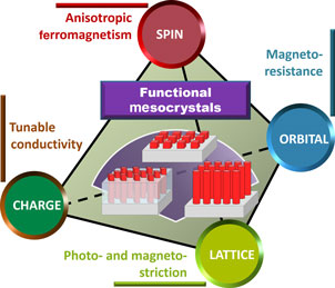
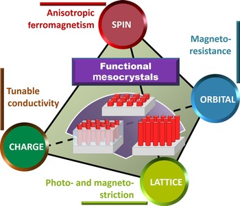
Figure 11 illustrates a summary on the intriguing properties as well as fascinating modulation achieved by the utilization of functional mesocrystals and oxide systems embedded with mesocrystal, by which researchers are essentially tailoring spin, orbital, charge, and lattice degrees of freedom behind the fascinating physics and phenomena. At the level of fundamental science, the research field of mesocrystal-embedded oxide systems offers a playground for the exploration of the coupling and interplay among different degrees of freedom, leading to exotic and novel functionalities that can be manipulated by external stimuli. Given that the modern computing and storage are operated electrically, the electrically controllable feature is the first theme to explore. However, in addition to electrically controllable functionality, one can imagine the manipulation of the emerging phenomena and various order parameters via other external stimuli, such as magnetic field and light, adding more flavors to existing technologies. To achieve this, researchers can start with new mesocrystal-embedded oxide systems by choosing materials that respond to different control parameters. Typical examples can be found in the nanocomposite that shows a strong photo-magnetic coupling between the photostrictive SRO matrix and the magnetostrictive CFO mesocrystal, and the nanocomposite which exhibits remarkable magnetoelectric coupling between the ferroelectric BFO matrix and the antiferromagnetic LiMn2O4 mesocrystal.[ Reference Eshghinejad, Liang, Chen, Ma, Liu, Xie, Chu and Li 84 , Reference Liang, Liu, Liao, Wang, Liu, Lin, Chen, Lai, Borisevich, Arenholz, Li and Chu 85 ]
Exploring new possibilities in functional mesocrystal-embedded oxide system, a theme to control spin, orbital, lattice, and charge degrees of freedom in functional oxide systems.
Moreover, other than the aforementioned mesocrystal-embedded oxide systems, the fabrication of new mesocrystals with different configurations will shed light on the route toward new possibilities. For example, Liao et al. demonstrated a mesocrystal system consisting of core–shell oxide nanocrystals, enabling researchers to create alternative ways to design magnetic systems.[ Reference Liao, Chen, Kuo, Cheung, Wang, Cheng, Chin, Chen, Liu, Lin, Chen, Juang, Chueh, Valanoor, Chu and Lai 86 ] In the study, the self-assembled antiferromagnetic–ferrimagnetic CoO–Co x Fe3−x O4 nanocrystals were used as building blocks to form one more branch of mesocrystals, a discrete core–shell mesocrystal.[ Reference Liao, Chen, Kuo, Cheung, Wang, Cheng, Chin, Chen, Liu, Lin, Chen, Juang, Chueh, Valanoor, Chu and Lai 86 ] The discrete core–shell nanocrystals were epitaxially grown on substrates, where the epitaxy sets the orientations of building nanocrystal blocks, resulting in a two-dimensional magnetic mesocrystal. Due to the epitaxy between selected materials and substrates, the OOP orientation, core–shell ratio, and core–shell sequence become key parameters to control the interfacial coupling to deliver desirable properties. New mesocrystal-embedded oxide systems with different material connectivity would further broaden the fertile functionalities of oxide materials.
Another scenario that can possibly be renovated via mesocrystal-embedded oxide systems is the dielectric and high-performance electromechanical functional materials. The dielectric properties of ferroelectric materials and polar insulators have been one of the central issues in condensed matter researches. Generally speaking, dielectric response is inversely proportional to the charge excitation gap.[ Reference Thouless 87 , Reference Onoda, Murakami and Nagaosa 88 ] That is to say, a small charge gap is needed to enhance the dielectric response and polarization. As a result, introducing a disorder potential into pure material systems serves as one of the most advantageous ways to enhance the dielectric properties, since the similar approaches have been adapted to modulate the localization effects.[ Reference Anderson 89 , Reference Lee and Ramakrishnan 90 ] The enhancement of the dielectric response of insulators by disorder is theoretically proposed by Onoda et al..[ Reference Onoda, Chern, Murakami, Ogimoto and Nagaosa 91 ] As predicted by the theoretical work, a disordered case with all the states being localized, the resonant tunneling plays a focal role to enhance the dielectric response by a factor 30–40 compared with the pure case.[ Reference Onoda, Chern, Murakami, Ogimoto and Nagaosa 91 ] Such a concept can be realized using mesocrystal-embedded systems. The combination of polar materials with randomly oriented electric polarization, e.g.: ZnO, and dielectric materials such as STO, might result in significantly enhanced dielectric response; while the combination of proper polar materials and ferroelectric system (such as BTO, BFO, and so on) could be used to induce disorder-enhanced ferroelectricy. The elegant combination of quantum theory and mesocrystal-embedded system offers promising potential to new dielectric and electromechanical systems, adding more features to new-generation capacitance and ferroelectric random access memory.
To date, one of the biggest challenges in the field of functional oxides today is the realization of practical applications. As a result, novel area corresponds to the device development, which enables one to pursue the goal of practical applications. Researchers have proposed the idea of electrically tunable magnetic devices, which manipulate the magnetism through the switching of ferroelectric polarization.[ Reference Bibes and Barthélémy 92 – Reference Matsukura, Tokura and Ohno 94 ] Current progress of electrical control of magnetism mainly are demonstrated at low-temperature, remaining a grand challenge. The utilization of new types of multiferroic based on mesocrystal-embedded system offers a promising route to overcome the natural limitation set by single-phase multiferroics. Another perspective that presents both scientific opportunities and challenges relates to the position control of nanocrystals, especially the conducting tubular interfaces in otherwise non-conducting constituents. In the recent studies, methods of fabricating highly ordered CFO mesocrystal-embedded in the BFO matrix have been demonstrated.[ Reference Stratulat, Lu, Morelli, Hesse, Erfurth and Alexe 95 , Reference Choi, Aimon, Kim, Sun, Gwyther, Manners and Ross 96 ] The nucleation centers of CFO are firstly created by the hard mask of gold or anodic aluminum oxide, followed by the deposition of the BFO–CFO mixed system after removing the hard mask. In this manner, the position and density of nanocrystals can be precisely controlled, and so does the tubular interface. The tubular oxide interfaces possess promising potential for being used in designing new electronic devices, not to mention the multifunctionalities that could be derived from the immeasurable combination of different ingredients. Further works with regard to the applications of tubular interfaces are under development, and will certainly arouse more intriguing interest in the near future.
In this article, we have captured a general picture for the concept and development of mesocrystal-embedded oxide systems, especially from the point of view of advanced functionalities. The mesocrystal-embedded nanocomposites offer huge advantages to accommodate versatile properties and to demolish the boundaries across disparate materials, not only act as the functional units, but also emerge as a new state of matter. Having reviewed the promising functionalities and potential advantages of the mesocrystal-embedded oxide systems, this review also concerns the future directions and goals to pursuit. The related field today remains poised for another great discovery that will usher another flurry of functional oxide systems, offering solutions to the major scientific questions human being have faced nowadays.
Acknowledgments
Our work was supported by the Ministry of Science and Technology, Taiwan (MOST 103-2119-M-009-003-MY3 and MOST 104-2628-E-009-005-MY2), Center for Interdisciplinary Science of National Chiao Tung University, Ministry of Education (MOE-ATU 101W961), and Academia Sinica Research Program on Nanoscience and Nanotechnology of Taiwan. The authors are not aware of any affiliations, memberships, funding, or financial holdings that might be perceived as affecting the objectivity of this perspective article.


