


Introduction
This paper is an extended version of [Reference Muckermann, Schmitz, Barowski and Pohl1], presented at the 54th European Microwave Conference and published in its proceedings. Radar sensors are used in a wide variety of applications. Depending on the application, antennas with different properties are crucial to fulfill special needs. Important aspects for selecting and designing an antenna are influenced by the frequency and properties of the antenna, such as directivity, side lobe level (SLL), gain, and antenna matching. For example, [Reference Armbrecht, Denicke, Pohl, Musch and Rolfes2] and [Reference Pohl and Gerding3] demonstrate that an increased directivity reduces measurement errors caused by disturbing targets. In [Reference Armbrecht, Zietz, Denicke and Rolfes4], the authors evaluate that antenna matching has a significant impact in mitigating measurement errors. Especially for applications with weak reflecting radar targets in short distances, the matching is increasingly relevant to ensure a reliable separation from internal reflections and prevent the detection of false targets.
A Tank Level Probing Radar (TLPR) represents one of many critical applications where weak target reflections must be reliably detected. Factors such as the reflection coefficient of certain liquids, the uneven distribution of bulk solids, or the presence of fog or dust in harsh industrial environments can significantly weaken the backscattered radar signals. Bypass pipes or contact-based sensors may be used to mitigate these effects [Reference Vogt5–Reference Kaineder, Michenthaler, Hammerschmidt and Stelzer7], but they are susceptible to contamination from material deposits, which can affect the sensor’s accuracy and dynamic response [Reference Wegner, Gebhardt and Del Galdo8]. Additional challenges arise from disturbing assemblies within tanks whose backscatter can interfere with or superimpose on the radar signal of the tank level [Reference Pohl and Gerding3, Reference Armbrecht, Zietz, Denicke and Rolfes4, Reference Vogt9].
In addition to the sensitivity of target reflections, separating the material inside a tank from the environment can be essential, particularly for substances that are hot, poisonous, under pressure, or even explosive. For these applications, a mechanical barrier is indispensable, which often has to be fulfilled by the radar antenna [Reference Vogt9–Reference Vogt and Gerding11].
Dielectric lens antennas are suitable to address these challenges. Their excellent antenna characteristics, in terms of gain, SLL, and angular width, compared with an equivalent horn antenna as in [Reference Armbrecht, Denicke, Pohl, Musch and Rolfes2, Reference Pohl and Gerding3], enable the measurement of weakly reflecting targets and help avoid disturbing reflections from structures within the tank. Furthermore, dielectric lens antennas can serve as a mechanical barrier for TLPRs and exhibit fewer internal reflections than dielectric lenses fed by a horn antenna [Reference Vogt, Schulz, Dahl, Rolfes and Gerding10, Reference Vogt and Gerding11]. However, internal reflections of dielectric lens antennas still limit the measurement range of TLPRs.
Due to their ellipsoidal design, an emitted electromagnetic wave is partially reflected from the antenna surface to the feed. It causes disturbances, which can lead to ghost targets and, therefore, incorrect detections. One possibility to decrease internal reflections is using matching layers between the lens body and air, as discussed in [Reference van der Vorst, de Maagt and Herben12]. However, this takes additional steps in manufacturing, and multiple matching layers can be necessary to optimize the result, as shown in [Reference Nguyen, Sauleau and Perez13].
In this work, we present a novel solution to address the problem of internal reflections using ellipsoidal dielectric lens antennas. Based on the idea we introduced in [Reference Muckermann, Barowski and Pohl14, Reference Muckermann, Barowski and Pohl15], we propose a Fresnel-based design of a far-field dielectric lens antenna. The proposed approach effectively reduces internal reflections, preserves the excellent antenna characteristics of conventional ellipsoidal lens antennas, and increases the usable near-distance measurement range for TLPR applications.
For this, in Section II, we first explain the origin of the reflections occurring when using ellipsoidal dielectric lens antennas and why they can be immensely reduced with our proposed Fresnel-based design. Afterward, we investigate the influence of a different number of steps on the Fresnel-based lens antenna’s characteristics in Section III. In Section IV, we address the manufacturing of a Fresnel-based lens antenna compared to an ellipsoidal lens antenna and the impact of manufacturing tolerances and the mechanical properties of both lenses. After that, the measurement results of the manufactured lens antennas are shown in Section V and compared to the expectations due to simulations. Finally, in Section VI, we present a TLPR scenario as an example of the beneficial characteristics of our Fresnel-based design for far-field lens antennas.
Reflection of dielectric lens antenna
Dielectric lens antennas are shaped dielectric materials that focus, collimate, or guide microwaves using refraction. However, in addition to the refraction at the lens’s surface, reflection occurs, which leads to disturbances and is investigated in the following. The examined lens antennas are based on the geometry of an ellipse. Therefore, we first show the design of an ellipse-based lens antenna and identify the source of internal reflections. Afterward, we present how our Fresnel-based design addresses this issue, reducing internal reflections to a minimum.
Ellipsoidal lens antenna
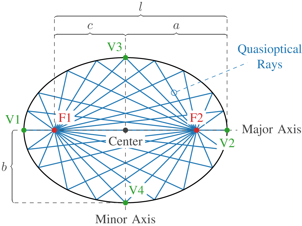
In [Reference Pohl16], Pohl uses an ellipse as a geometric optic approach to design an ellipsoidal lens antenna that collimates the electromagnetic waves from a radar. Fig. 1 illustrates an ellipse with dimensions  $a$,
$a$,  $b$,
$b$,  $c$ and $l$. Here, $a$ is the semi-major axis, the distance between the center and the vertex V1 or V2. It is used as the rotational axis to create an ellipsoid from the ellipse. The semi-minor axis is given by $b$, the distance from the center to the vertex V3 or V4, resulting in the radius $r$ of an ellipsoidal lens antenna. The distance between the center and one of the focal points, F1 or F2, is named $c$. The length of an ellipsoidal lens antenna is $l=a+c$. For a collimating lens antenna, the ratio of the major and minor axes can be derived from [Reference Pohl16] as the relation of the relative permittivity of the surrounding media $\varepsilon_\mathrm{r,{media}}$ to the relative permittivity of the dielectric of the lens $\varepsilon_\mathrm{r,{lens}}$:
 \begin{equation}
\frac{a}{b}=\frac{1}{\sqrt{1-\frac{\varepsilon_\mathrm{r,{media}}}{\varepsilon_\mathrm{r,{lens}}}}}.
\end{equation}
\begin{equation}
\frac{a}{b}=\frac{1}{\sqrt{1-\frac{\varepsilon_\mathrm{r,{media}}}{\varepsilon_\mathrm{r,{lens}}}}}.
\end{equation}Geometry of an ellipse with its two focal points F1 and F2. Quasioptical rays show the focal point characteristic exemplarily: each ray originating from one focal point is reflected by the surface of the ellipse to the other focal point.

As the distance from one focal point to the other via an arbitrary point on the ellipse is  $2a$ [Reference Stewart17], the distance between one focal point and one of the vertices V3 or V4 is $a$. The value of $c$ can therefore be calculated using:
 \begin{equation}
c=\sqrt{a^2-b^2}.
\end{equation}
\begin{equation}
c=\sqrt{a^2-b^2}.
\end{equation}In Fig. 1, quasioptical rays demonstrate the focal point characteristic of an ellipse. The focal point characteristic describes that each ray originating from one focal point is reflected by the surface of the ellipse to the other focal point. This is particularly important for an ellipsoidal lens antenna, as one of the two focal points serves as the feed for electromagnetic waves, enabling the lens to achieve a collimating behavior. Therefore, the ellipse part between the used focal point and the neighboring vertex is removed, as done in Fig. 2. The resulting lens antenna is fed from a WR10 rectangular waveguide. To match the transition from the waveguide to the lens material, a two-step impedance transformer is used, as previously employed with a single step in [Reference Pohl and Gerding3, Reference Pohl16]. Feeding the antenna via a rectangular waveguide enables compatibility with a wide variety of devices and provides high flexibility.
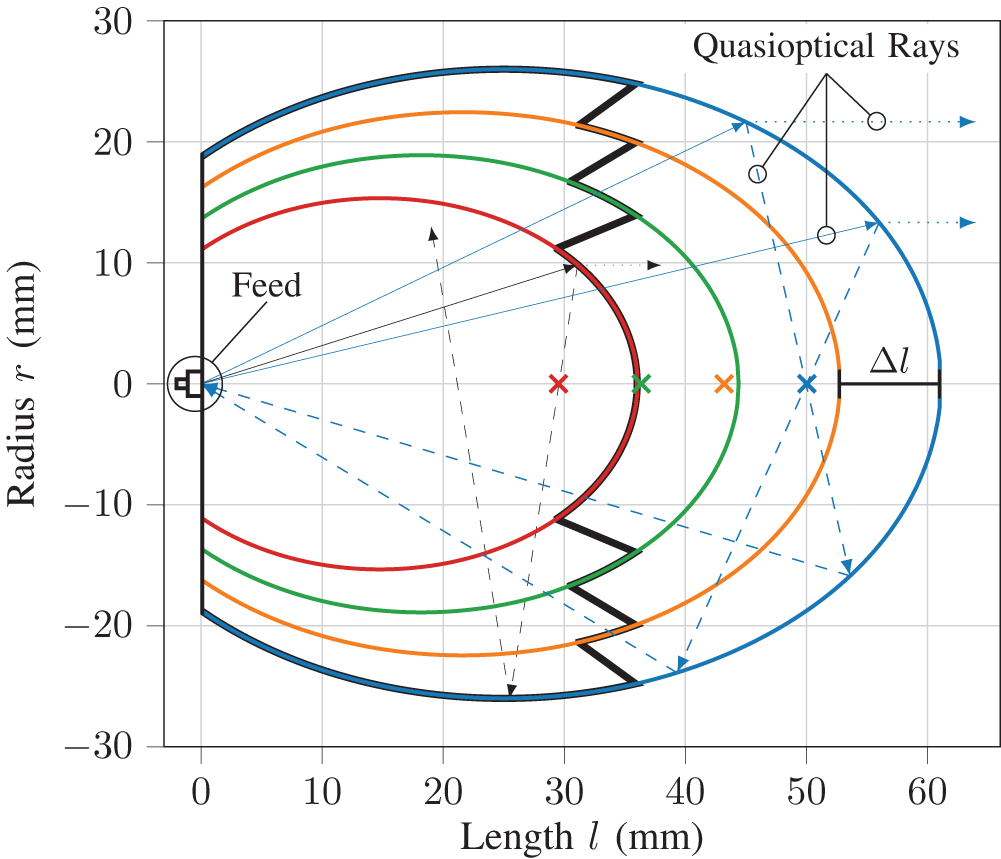
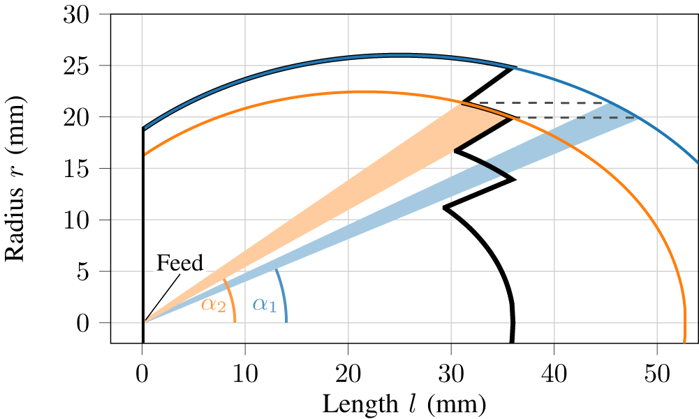
Different-sized ellipses (color-coded), which are used to design the Fresnel-based lens (black). The step size  $\Delta l$ between two adjacent ellipses is exemplified for the blue and orange ellipses. All ellipses are aligned with their left focal point, which serves as the feed location. The feed is implemented using a two-step impedance transformer, following the approach in [Reference Pohl and Gerding3, Reference Pohl16], to match the lens to a WR10 rectangular waveguide. The portion of each ellipse situated to the left of the feed is disregarded. The right focal point of each ellipse is marked with a color-coded cross. Quasioptical rays (black, blue) exemplarily show the refraction (dotted) and reflection (dashed) occurring at the respective lens surface.

From a geometrical optics perspective, the electromagnetic waves fed to the lens can be approximated as quasioptical rays. They emit from the feed in all directions. Upon reaching the lens surface, they undergo partial refraction, forming a collimated beam with plane phase fronts. The other portion of these rays is reflected and remains within the lens body (see Fig. 2). Due to the focal point characteristic, all reflected rays propagate through the other focal point, which will hereafter be referred to as the second focal point. Since these reflected rays once again originate from a focal point, the subsequent reflection redirects all rays back to the focal point, which is the feed of the lens antenna. As the distance from one focal point to the other via any point on the ellipse is constant and equal to  $2a$, all rays constructively overlap at the feed. This creates an internal reflection within the ellipsoidal lens antenna, which, in measurements, may be misinterpreted as a target, which does not exist, henceforth named ghost target.
The ghost target has a time delay of
 \begin{equation}
\tau_\mathrm{ghost}=\frac{4a}{c_\mathrm{lens}}.
\end{equation}
\begin{equation}
\tau_\mathrm{ghost}=\frac{4a}{c_\mathrm{lens}}.
\end{equation}A target precisely at the vertex opposite the feed, however, has only a time delay of
 \begin{equation}
\tau_\mathrm{vertex}=\frac{2(a+c)}{c_\mathrm{lens}}.
\end{equation}
\begin{equation}
\tau_\mathrm{vertex}=\frac{2(a+c)}{c_\mathrm{lens}}.
\end{equation}This leads to the ghost target appearing
 \begin{equation}
\Delta\tau = \tau_\mathrm{ghost}-\tau_\mathrm{vertex}= \frac{2(a-c)}{c_\mathrm{lens}}
\end{equation}
\begin{equation}
\Delta\tau = \tau_\mathrm{ghost}-\tau_\mathrm{vertex}= \frac{2(a-c)}{c_\mathrm{lens}}
\end{equation} in front of the lens, whereas in Equation 3 to 5,  $c_\mathrm{lens}$ is the propagation speed of electromagnetic waves inside the lens. Consequently, a target positioned in front of the lens at a distance corresponding to $\Delta \tau$ may be obscured or distorted by the internal reflections, which could also be mistaken for a target. These effects make it necessary to restrict the measurement range for certain scenarios.
Fresnel-based lens antenna
Section II.A explains how the focal point characteristic of an ellipse leads to internal reflections of ellipsoidal lens antennas. To minimize these reflections, we use a Fresnel-based design, introduced in our previous work in [Reference Muckermann, Barowski and Pohl14, Reference Muckermann, Barowski and Pohl15], where it is used to design focusing lens antennas. Here, we use the design to interrupt the focal point characteristic of the ellipse while retaining the other beamforming characteristics of an ellipsoidal lens antenna. Therefore, we modify the shape of the ellipsoid so that the second focal point, which is not the feed but an essential part of the focal point characteristic, is no longer inside but outside the lens antenna.
Figure 2 illustrates the design concept. Different-sized ellipses (color-coded) are used, whereas the largest and outermost ellipse (blue) corresponds to the equivalent ellipsoidal lens antenna, and the shortest lens is chosen to be longer than the distance between the feed and the center of the outermost ellipse:
 \begin{equation}
c_\mathrm{shortest}+a_\mathrm{shortest} \gt c_\mathrm{outermost}.
\end{equation}
\begin{equation}
c_\mathrm{shortest}+a_\mathrm{shortest} \gt c_\mathrm{outermost}.
\end{equation}This is done to retain the largest diameter of the outermost ellipse, as it defines the aperture diameter, a fundamental parameter in collimating optics. A. E. Siegman describes the angular diffraction spread in [Reference Siegman18] as
 \begin{equation}
\Delta\theta \approx \frac\lambda {D} \qquad\text{(in radians)},
\end{equation}
\begin{equation}
\Delta\theta \approx \frac\lambda {D} \qquad\text{(in radians)},
\end{equation} where  $\lambda$ denotes the wavelength, and $D$ represents the diameter of the aperture, corresponding to the lens diameter $2b$. The angular diffraction spread contributes to the beam’s divergence, making it crucial to maintain the lens diameter to achieve a well-collimated beam with a small beamwidth and a high antenna gain.
The step size  $\Delta l$ is defined as the difference in length $l= a+c$ between two adjacent ellipses $i$ and $i+1$:
 \begin{equation}
\Delta l = l_i - l_{i+1}= (a_i+c_i)-(a_{i+1}+c_{i+1}).
\end{equation}
\begin{equation}
\Delta l = l_i - l_{i+1}= (a_i+c_i)-(a_{i+1}+c_{i+1}).
\end{equation}The step size ensures constructive interference of the collimated beams from all ellipses in free space, as described in [Reference Muckermann, Barowski and Pohl14, Reference Muckermann, Barowski and Pohl15], using the equation
 \begin{equation}
\Delta l = \frac{f_\mathrm{center}}{c_0\cdot\left(1-\sqrt{\frac{\varepsilon_\mathrm{r,{lens}}}{\varepsilon_\mathrm{r,{media}}}}\right)},
\end{equation}
\begin{equation}
\Delta l = \frac{f_\mathrm{center}}{c_0\cdot\left(1-\sqrt{\frac{\varepsilon_\mathrm{r,{lens}}}{\varepsilon_\mathrm{r,{media}}}}\right)},
\end{equation} whereas  $f_\mathrm{center}$ is the center frequency of the system the lens antenna is intended for, and $c_0$ is the propagation speed of electromagnetic waves in a vacuum.
The different-sized ellipses are aligned in their left focal point, which is used as the feed, and are truncated to the length of the shortest ellipse, shown in red. The transitions between adjacent ellipses are angled towards the feed to prevent smaller inner ellipses from shadowing larger outer ones. The resulting Fresnel-based design is depicted as the black shape in Fig. 2.
Our Fresnel-based design is evidently shorter than the largest ellipse (colored in blue) but retains its diameter. The shorter shape not only leads to more compactness and weight reduction of the lens antenna, but by shortening the shape, three focal points of the four ellipses are outside the new shape. These outside foci interrupt the inner reflections. Reflected rays, that aim to cross these focal points, hit the surface of the Fresnel-based design and are reflected in other directions than back to the feed. Only the focal point of the shortest ellipse (colored in red) remains inside. However, this ellipse is only a small part of the Fresnel-based design, and rays, which are reflected by this ellipse can reach its focal point identified by the red cross but do not hit a surface that belongs to the corresponding ellipse afterward, as indicated by the black rays in Fig. 2. Instead, they hit the outermost ellipse (colored in blue), which does not reflect these rays towards the feed because it originates from a focal point of another different-sized lens. If a ray is directed toward the feed after multiple reflections inside the lens, the attenuation by the losses of the lens material reduces its amplitude and makes it negligible. Therefore, fewer reflections from the surface return to the feed, and the internal reflections, which might disturb the measurement, decrease.
Number of Fresnel steps
In this section, we investigate the influence of the number of steps on the characteristics of the Fresnel-based lens antenna. Assuming the dimensions of the outermost ellipse are given, the maximum number of smaller ellipses and, therefore, steps of the design are calculated using the step size from Equation 9 and the limit for the smallest ellipse given by Equation 6. However, it is possible not to use all potential ellipses when designing the Fresnel-based lens antenna.
The calculations are based on the 80 GHz center frequency of the ultra-wideband Frequency-Modulated Continuous-Wave (FMCW) radar presented in [Reference Pohl, Jaeschke, Küppers, Bredendiek and Nüßler19], which features a bandwidth of 24 GHz and is used for the measurements described in Sections V and VI. Polytetrafluoroethylene (PTFE) is chosen as the lens material due to its favorable high-frequency properties, including a low and frequency-stable relative permittivity  $\varepsilon_\mathrm{r}$ and a low dissipation factor $\tan(\delta)$. Furthermore, the diameter of the outer lens is 52 mm, corresponding to approximately 13.87 wavelengths at the center frequency of 80 GHz (
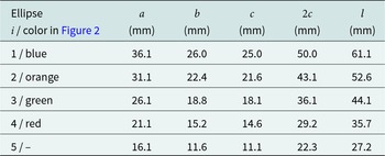
 $\lambda_\mathrm{c}\approx$ 3.75 mm). With these conditions, the Fresnel-based design can have five or fewer steps. Table 1 gives the dimensions of all ellipses and the length $l$ of each corresponding ellipsoidal lens antenna, calculated as $a+c$.
Dimensions of ellipses for a Fresnel-based lens antenna with 52 mm diameter and 80 GHz center frequency. Parameter as in Figure 1 with  $l= a+c$

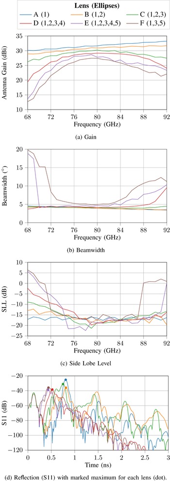
Figure 3 shows simulations conducted in CST Microwave Studio, illustrating the gain, the 3-dB beamwidth, the SLL, and the antenna reflection (S11) over frequency for different combinations of ellipses. Each ellipse is once considered the smallest. Additionally, for ellipse 5, every second ellipse is skipped, resulting in a Fresnel-based design consisting of ellipses 1, 3 and 5. The lens antennas are named from A to F, as shown in the legend of Fig. 3.
Simulated (a) gain, (b) beamwidth, (c) side lobe level (SLL), and (d) S11 for ellipsoidal and Fresnel-based lens antennas with different number of steps.

In Fig. 3a, the frequency dependency of the gain of the Fresnel-based designs is displayed. For frequencies that deviate strongly from the center frequency, the gain decreases. This is due to step size  $\Delta l$, which is designed using the center frequency of 80 GHz. However, also for the center frequency, the gain decreases the more steps are used. This is attributed to the opening angle of the feed. Although the feed has a 3-dB opening angle of approximately 63 $^{\circ}$, it results in weaker electromagnetic waves at larger radii. This mainly affects the shorter Fresnel-based lens antennas with more steps.
Figure 4 illustrates the angles  $\alpha_1$ and $\alpha_2$ required to reach the same radii at ellipse 1 or 2 in the Fresnel-based design. At $\alpha_2$, the gain is 2.9 dB lower than at $\alpha_1$. Therefore, shorter Fresnel-based lens antennas are weaker illuminated at greater radii, which leads to a lower gain, as larger radii significantly contribute to achieving a well-collimated beam and higher gain.
Illumination of ellipses 1 (blue) and 2 (orange) at the same radii with different angles from a common feed.

The lowest gain has lens F, which is a combination of ellipses 1, 3, and 5, although the Fresnel-based lens antenna has the same length as lens E, which also has ellipse 5 as the shortest. One reason for this is the greater gaps between adjacent ellipses, which increase the previously outlined effect of weaker illumination at higher angles (see Fig. 4). Furthermore, the angled transitions between two ellipses are longer but do not contribute to the collimation of the lens.
The beamwidth over frequency for the different combinations is shown in Fig. 3b. Similar to the gain, combinations with fewer ellipses are more closely related to the behavior of the ellipsoidal lens antenna with only one ellipse. Notably, both lenses E and F, where ellipse 5 is the smallest ellipse, exhibit significantly greater beamwidths at the edges of the frequency range from 68 GHz to 92 GHz. The beamwidth of lens D also increases at the highest frequencies but remains mainly constant and close to that of the ellipsoidal lens antenna (lens A) over a wide frequency range.
A comparable behavior can be observed for the SLL (Fig. 3c). Similarly, lenses E and F show considerably higher side lobes at the edges of the considered frequency range. However, the other lenses also indicate increasing side lobes, but only at the lower frequencies. The shorter the smallest ellipse is, the higher are the side lobes at lower frequencies. For the remaining frequency range, the side lobes are reasonably constant.
Figure 3d illustrates the reflection of the lenses using the scattering parameter S11, which also shows the internal reflections. For each lens, the maximum reflection is marked with a dot. Lens A exhibits the highest internal reflection, but lenses B and C also show higher reflections and more multiple reflections compared to lenses D, E, and F. This behavior is due to the position of each second focal point of the ellipses the respective lens consists of.
Table 1 lists the length of each lens, calculated as  $a+c$, and the distance between the two focal points of each lens ( $2c$), which determines the position of each second focal point. A comparison of the values reveals that not all combinations of ellipses achieve the desired result that all second focal points, except for that of the smallest ellipse, are positioned outside the Fresnel-based lens antenna. For lenses E, D, and F, where ellipses 4 or 5 are used as the smallest ellipse, the second focal points of all larger ellipses lie outside the Fresnel-based lens antenna.
Conversely, lens C, with ellipse 3 as the smallest ellipse, has the second focal point of ellipse 2 remaining within the lens body. This can also be seen in Fig. 2, where the focal point indicated by the orange cross is within the green ellipse. Similarly, for lens B, where ellipse 2 is the smallest, the second focal point of ellipse 1 is also inside the lens body. In both cases, the focal point characteristic partly persists, which prevents the elimination of internal reflections. This explains why the internal reflections for lenses B and C remain high, with multiple reflections occurring, despite the use of the Fresnel-based design.
Nevertheless, Fig. 3d clearly demonstrates that the Fresnel-based design can reduce internal reflections compared to an ellipsoidal lens antenna, provided the number of steps is chosen correctly. However, a frequency-dependent behavior exists, which is influenced by the number of steps. Lens D offers the best overall performance of the Fresnel-based lenses, with significantly reduced internal reflections and an acceptable frequency-dependent behavior. Considering that the bandwidth is restricted to 75 GHz to 85 GHz in commercial TLPR applications according to the ETSI EN 302 729 V2.1.1 standard, variations of the gain, beamwidth, and SLL within this range are only minor.
Manufacturing tolerances
This section investigates the manufacturing of lenses A and D and the influence of manufacturing tolerances on their performance using simulations conducted in CST Microwave Studio.
After detailed consideration of the effects of the number of steps in the Fresnel-based design in Section III, lenses A and D are manufactured using turning and milling processes. Both lenses are made of PTFE due to its low and frequency-stable relative permittivity  $\varepsilon_\mathrm{r}$ and its low dissipation factor
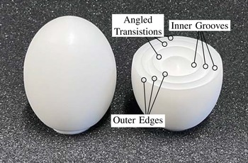
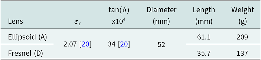
  $\tan(\delta)$. The manufactured lenses are pictured in Fig. 5, and their properties and dimensions are listed in Table 2. While the diameter of both lenses is equal, the Fresnel-based lens antenna is 41% shorter and 34% lighter.
Ellipsoidal lens antenna (A) on the left and Fresnel-based lens antenna (D) on the right. Inner grooves, outer edges, and angled transitions of the Fresnel-based lens antenna are labeled.

Material properties of PTFE and dimensions of ellipsoidal lens antenna (A) and Fresnel-based lens antenna (D)

In comparison to the ellipsoidal lens antenna, the Fresnel-based lens antenna brings more complexity in manufacturing. This includes the radii of the inner grooves and outer edges of the Fresnel structure and deviations of the angle of the transitions between two ellipses in the Fresnel-based design. The inner grooves, outer edges, and angled transitions are marked in Fig. 5.
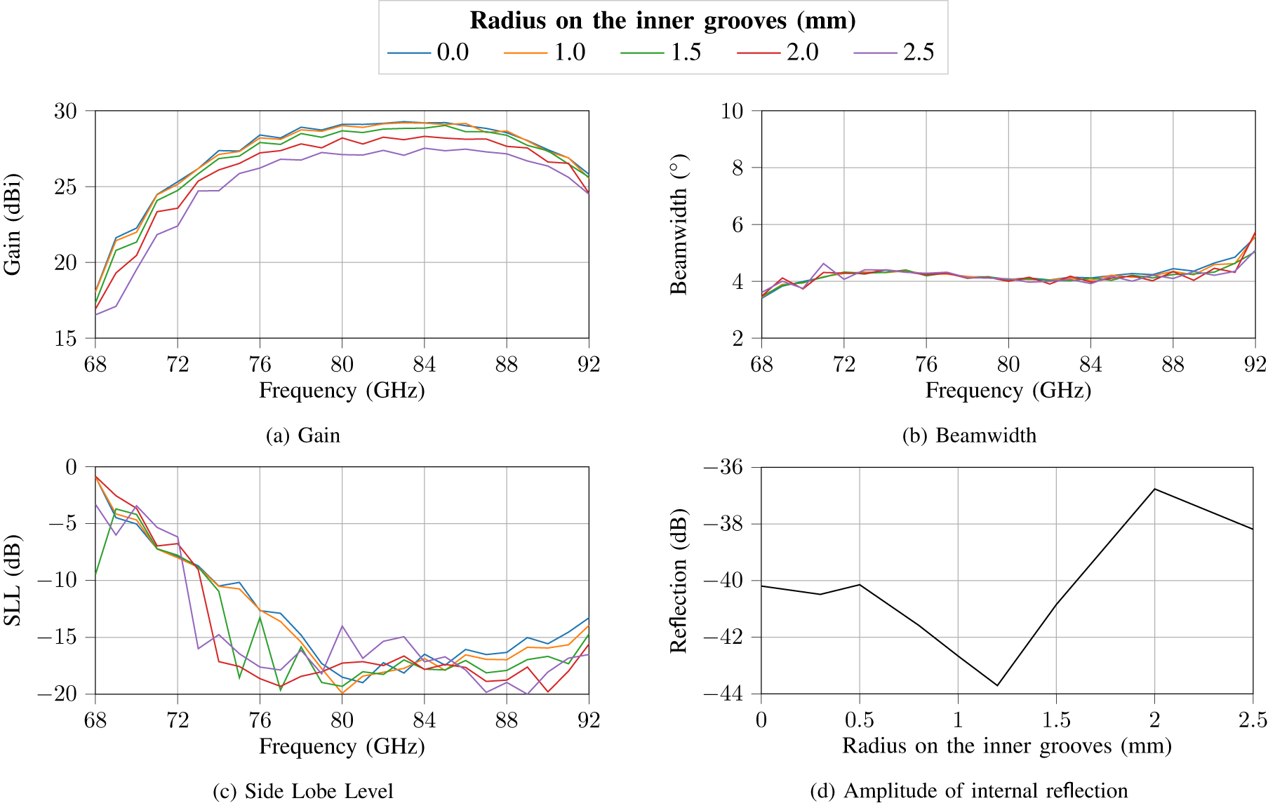
Figure 6 shows the gain, beamwidth, SLL, and the amplitude of the internal reflection of the Fresnel-based lens antenna for different radii from 0 mm to 2.5 mm of the inner grooves in the Fresnel structure. The inner grooves are more challenging to access with milling machines as they are only reachable within a limited angle. As a result, radii up to 1 mm can quickly happen. However, larger radii of 2 mm or even 2.5 mm pose no significant challenge for milling machines. In Fig. 6a, a radius of 1 mm shows nearly no change in gain compared to a radius of 0 mm. A slight decrease in gain becomes apparent for radii of 1.5 mm or larger. The beamwidth in Fig. 6b remains almost unchanged for different radii, and the SLL is only slightly affected by radii of 1.5 mm or more. The internal reflection even declines for small radii before it increases for radii higher than 1.5 mm (Fig. 6d).
Simulated (a) gain, (b) beamwidth, (c) side lobe level (SLL), and (d) internal reflection with different radii at the inner grooves due to manufacturing tolerances.

The outer edges of the Fresnel structure are easier to access than the inner grooves, and smaller radii are achievable. However, larger radii could be the consequence of mechanical damage or could be intentionally designed to enhance robustness against such damage. The impact of outer edges radii of up to 2 mm on the lens is illustrated in Fig. 7. The gain remains nearly unchanged for a small radius of 0.5 mm. For larger radii, it starts to decrease more significantly than for the inner groove radii.
On the other hand, the beamwidth shows minimal deviations even for higher radii. Noticeable deviations occur only for radii of 1.5 mm or more at higher frequencies (see Fig. 7b). The SLL, depicted in Fig. 7c, worsens for larger radii, which could also be attributed to the lower gain for these radii. The internal reflections, similar to the inner grooves, decrease for small radii up to 0.5 mm but then begin to rise slightly as the radius increases.
Simulated (a) gain, (b) beamwidth, (c) side lobe level (SLL), and (d) internal reflection with different radii at the outer edges due to manufacturing tolerances.

Lastly, the angled transitions between two ellipses are considered to determine whether the chosen angles, which are aligned towards the feed, are the best choice. Simulations were conducted for angle offsets ranging from +15 $^{\circ}$ to -15 $^{\circ}$, where positive angles represent shallower transitions from the feed’s perspective, and negative angles represent steeper ones. As shown in Fig. 8a, the gain begins to decrease only for offsets of 10 $^{\circ}$ or more in both directions. The beamwidth, depicted in Fig. 8b, remains nearly constant across all angles, with slight deviations observed at -10 $^{\circ}$ and -15 $^{\circ}$ in the frequency range from 75 GHz to 90 GHz. The SLL, presented in Fig. 8c, shows minor deviations only for an angle offset of -15 $^{\circ}$ around the center frequency. The internal reflection, shown in Fig. 8d, reaches a minimum at 0 $^{\circ}$ and increases for angle offsets in both directions. Only for an offset of +15 $^{\circ}$ is the internal reflection reduced compared to the offset of 0 $^{\circ}$. Overall, the offset of 0 $^{\circ}$ provides the best performance, confirming the chosen angles.
Simulated (a) gain, (b) beamwidth, (c) side lobe level (SLL), and (d) internal reflection with different angled transitions between two adjacent ellipses due to manufacturing tolerances.

For all investigated manufacturing tolerances, the impact on the performance of the Fresnel-based lens antenna was found to be minimal compared to the variations caused by frequency. Therefore, although the Fresnel-based lens antenna requires more complex manufacturing, the tolerance requirements are not a limitation and can be easily met using standard machinery.
Measurements
Antenna characteristics
To comprehensively compare both lens antennas, we evaluate their characteristics using simulations conducted in CST Microwave Studio and measurements performed with the setup shown in Fig. 9.
Setup for measuring the radiation pattern of both lens antennas. The setup consists of an ultra-wideband FMCW radar placed on a rotation stage and a corner reflector with a side length of 20 mm.

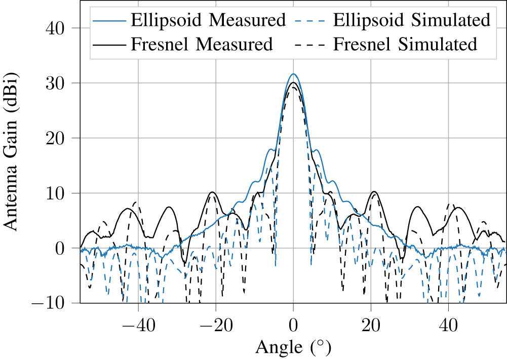
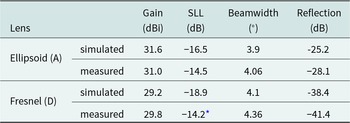
Figure 10 illustrates the radiation pattern, and Table 3 summarizes key characteristics of both lenses. The simulated results refer to a center frequency of 80 GHz. The measurements were performed in an anechoic chamber using the ultra-wideband FMCW radar described in [Reference Pohl, Jaeschke, Küppers, Bredendiek and Nüßler19], which provides a 24 GHz bandwidth and a center frequency of 80 GHz. A wideband microstrip-to-waveguide transition (see [Reference Pohl, Jaeschke and Aufinger21, Reference Pohl, Jaeschke and Vogt22]) connects the radar to a 10 mm long WR10 rectangular waveguide, which feeds the lens antenna via the two-step impedance transformer illustrated in Fig. 2. The measurement setup, as shown in Fig. 9, consists of the radar system mounted on a tripod, which is placed on a rotation stage, and a corner reflector with a side length of 20 mm, positioned at a distance of 2 m. This distance exceeds the Fraunhofer far-field limit of the lens antennas, while still being close enough to ensure sufficient reflected power for a detailed radiation pattern. A 25 dBi standard gain horn is used as a reference antenna.
Simulated and measured radiation pattern for ellipsoidal and Fresnel-based lens antenna. The simulations are conducted at a frequency of 80 GHz. The measurements use an FMCW radar with a center frequency of 80 GHz and a bandwidth of 24 GHz.

Simulated and measured characteristics of ellipsoidal lens antenna (A) and Fresnel-based lens antenna (D)

* ± 0.2dB because first side lobe is hardly recognizable
The simulations and measurements demonstrate good agreement. As expected, the ellipsoidal lens antenna exhibits a slightly higher gain than the Fresnel-based lens antenna. Similarly, the SLL and the beamwidth in the measurements align well with the simulations. At angles exceeding  $20^{\circ}$, it is evident that the Fresnel-based lens antenna has higher side lobes compared to the ellipsoidal lens antenna in both simulations and measurements. However, these side lobes remain more than 20 dB below the main lobe.
Overall, the Fresnel-based lens antenna demonstrates a performance comparable to the ellipsoidal lens antenna, with only marginally worse results. This aligns with prior expectations given the same lens diameter and the simulation results from Fig. 3.
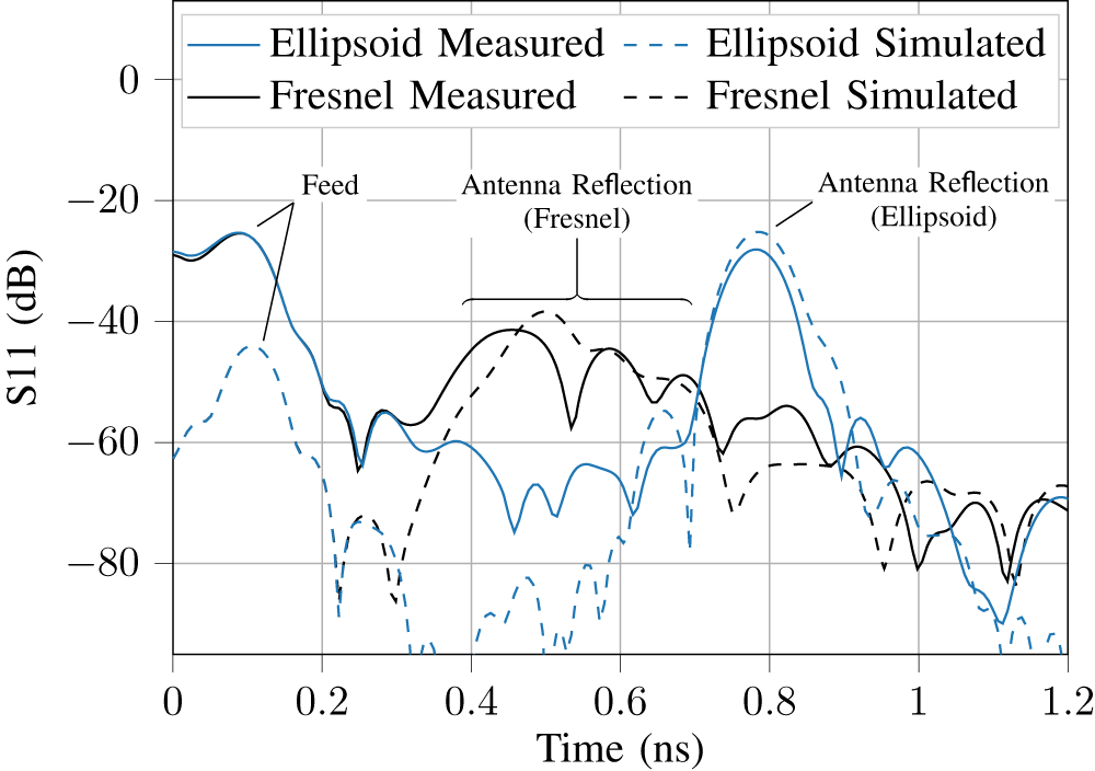
In Fig. 11, the reflection characteristics of both lenses are presented, as simulated and measured. The measurements were performed using a TLR-calibrated network analyzer (Keysight PNA-X with W-band frequency extension module).
Simulated and measured reflection (S11) for ellipsoidal and Fresnel-based lens antenna.

Notably, the Fresnel-based lens antenna exhibits an antenna reflection that is 13.3 dB lower in the measured value and appears closer to the feed compared to the ellipsoidal lens antenna. However, the antenna reflection of the Fresnel-based lens antenna consists of multiple closely spaced reflections, which are more pronounced in the measurements than in the simulations. In contrast, the ellipsoidal lens antenna has only one significant reflection, leading to disturbing multiple reflections, as shown in Fig. 3d.
For both lens antennas, the measured antenna reflections are slightly lower than expected from the simulations. This discrepancy may be attributed to higher dielectric losses in the actual antenna material compared to the values assumed in the simulations. Additionally, a lower relative permittivity of the lens material would reduce reflections due to the smaller impedance contrast with the surrounding medium (air). Another contributing factor might be the significantly poorer matching at the feed observed in the measurements, as illustrated in Fig. 11. This issue may arise from the fine and difficult-to-manufacture structure of the two-step impedance transformer used, which is also prone to deviations in the relative permittivity of the lens material. Slight deviations in the feed structure can lead to significantly poorer matching, increased reflections, and less power coupled into the lens.
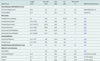
Table 4 compares our proposed lens antennas with commercial and state-of-the-art alternatives. As expected from Equation 7, achieving higher gain and a narrower beam requires a larger aperture diameter. Nevertheless, the presented lenses outperform other antennas with comparable diameters and demonstrate competitive performance even when compared to antennas with significantly larger apertures. Only the horn antennas with a dielectric cone achieve similar performance at a comparable aperture diameter, but at the expense of a greater length than our Fresnel-based lens antenna.
Characteristics of different dielectric lenses in the W-band

— missing or unspecified information
* commercial products  $^\dagger$ value read from diagram $^\ddagger$ focal distance to feeder
Frequency dependency
The measurements shown in Fig. 10 and Fig. 11 were carried out using a bandwidth of 24 GHz. As reported in [Reference Muckermann, Barowski and Pohl14, Reference Muckermann, Barowski and Pohl15] and shown in Fig. 3a to Fig. 3c, there is a frequency-dependent behavior of the Fresnel-based design due to the step size  $\Delta l$, which is optimized for the center frequency of 80 GHz. In the following, we investigate the influence of measurement frequency and bandwidth on the gain, beamwidth, and SLL of Fresnel-based lens D in comparison to ellipsoidal lens A.
In Fig. 12, measurement results with bandwidths ranging from 1 GHz to 24 GHz and center frequencies from 68.5 GHz to 91.5 GHz for both lenses are presented alongside simulations performed in CST Microwave Studio. Both lenses, A and D, show negligible deviations for varying bandwidths. However, for different center frequencies, a frequency-dependent behavior becomes evident.
Measured and simulated gain, beamwidth, and side lobe level (SLL) of lens A in (a), (c), and (e) and lens D in (b), (d), and (f) for bandwidths from 1 GHz to 24 GHz and center frequencies from 68.5 GHz to 91.5 GHz.

The gain of lens A (Fig. 12a) increases by approximately 3 dB with rising center frequencies in both simulation and measurement. This behavior results from the reduced angular diffraction spread at shorter wavelengths, as described by Equation 7. Conversely, the gain of lens D (Fig. 12b) decreases for frequencies deviating from the center frequency of 80 GHz. This is attributed to the frequency-dependent step size  $\Delta l$ of the Fresnel-based lens, as defined in Equation 9. The influence of the step size outweighs the frequency-dependent angular diffraction spread, though the angular diffraction spread also leads to a smaller drop in gain at higher frequencies for lens D.
Examining the beamwidth, lens A shows a linear decrease with increasing center frequencies in Fig. 12c, which also aligns with Equation 7. For lens D, the beamwidth in Fig. 12d likewise decreases with increasing frequencies up to 80 GHz. From then on, the beamwidth increases with frequency, initially slightly and then more significantly. For both lenses, the beamwidth closely matches the simulations.
The SLL of lens A in Fig. 12e remains consistent across all center frequencies with only minor deviations, apart from a single outlier at 89.5 GHz. Notably, the measured SLL of lens A is slightly worse than expected from the simulations. For Lens D, the SLL, depicted in Fig. 12f, stays constantly low over a wide range of center frequencies but increases at the edges of the frequency range, first gradually and then more steeply.
Overall, the measurement results are in good agreement with the simulations. Higher bandwidths do not cause significant deviations, but center frequencies that deviate substantially from the design frequency of 80 GHz result in observable changes, especially for lens D, leading to worse antenna characteristics for this lens.
Tank level probing scenario
The presented Fresnel-based design demonstrates significant advantages in detecting weakly reflecting targets located close to the lens, which might otherwise be masked or misinterpreted by antenna reflections. TLPRs often impose such requirements and benefit from the Fresnel-based lens antenna’s narrow beamwidth, high gain, and short length. These features minimize the risk of interference from disturbing obstacles within the tank and reduce the intrusion of the antenna into the tank environment.
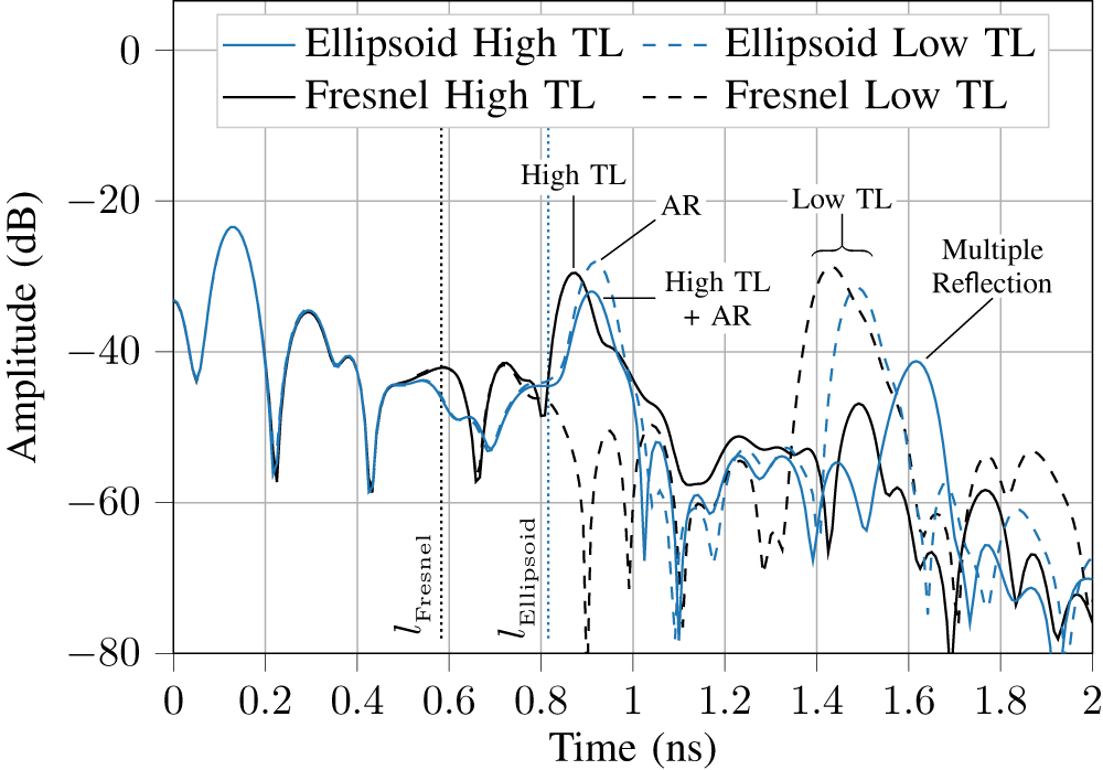
To demonstrate these advantages, we conducted TLPR measurements with the ellipsoidal and Fresnel-based lens antenna using sunflower oil as a test liquid. For the measurements, we used the FMCW radar from [Reference Pohl, Jaeschke, Küppers, Bredendiek and Nüßler19] with a bandwidth of 24 GHz and a center frequency of 80 GHz. Different tank levels (TLs) were imitated using the measurement setup shown in Fig. 13. The FMCW radar system is mounted on a linear stage, allowing positioning at different heights above a bucket filled with sunflower oil, which has a low permittivity, resulting in small reflections. Figure 14 shows measurements with both lens antennas for high and low TLs.
Measurement setup for TLPR with FMCW radar on a linear stage above a bucket filled with sunflower oil.

Measurement of high and low tank levels (TL) using ellipsoidal and Fresnel-based lens antenna with labeled antenna reflections (AR). Dotted lines indicate the length of each lens antenna.

At the high TL, the ellipsoidal lens antenna is positioned 17 mm above the surface of the oil, while at the low TL, this distance increased to 100 mm. Identical positions on the linear stage were used for the Fresnel-based lens antenna, resulting in greater distances in both TL scenarios due to its shorter length. The lengths of both lenses,  $l_\mathrm{Ellipsoid}$ and $l_\mathrm{Fresnel}$, are marked in Fig. 14 by dotted lines, indicating the TLs where the oil comes into contact with the respective lens antenna.
For a low TL, both lens antennas exhibit a clearly distinguishable reflection. Notably, the antenna reflection (AR) of the ellipsoidal lens antenna is higher than the reflection of the low TL. At the higher TL, the AR of the ellipsoidal lens antenna interferes destructively with the reflection from the oil surface, resulting in a peak amplitude smaller than the AR at the low TL. This could lead to a misinterpretation, where the first multiple reflection at approximately 1.6 ns might be incorrectly identified as the actual TL, leading to a significant measurement error.
In contrast, the Fresnel-based lens antenna maintains a distinctly identifiable reflection from the high TL, with an amplitude almost identical to that of the low TL. This ensures reliable detection of the TL until the Fresnel-based lens antenna contacts the oil surface.
Therefore, an increase in measurable TL arises due to the shorter length and much lower antenna reflections of the Fresnel-based lens compared to the ellipsoidal lens. The increase can be calculated by adding up the length difference between lenses A and D of 25.4 mm (see Table 1), the distance between the vertex of lens A and the ghost target, which can be calculated to 16 mm using Equation 5 and the range resolution of the radar to separate the TL from the ghost target clearly. The range resolution  $\Delta R$ of the radar system in use, primarily influenced by its bandwidth, is according to the Rayleigh-Criterion and assuming a rectangular window function, given by
 \begin{equation}
\Delta R =\frac{c_0}{2\cdot B} .
\end{equation}
\begin{equation}
\Delta R =\frac{c_0}{2\cdot B} .
\end{equation}Considering the FMCW radar system’s ultra-wide bandwidth of 24 GHz, the range resolution is 6.2 mm. Altogether, we get an increase of measurable TL of 47.6 mm for the Fresnel-based lens antenna compared to the ellipsoidal lens antenna. This difference would be even more remarkable considering the lower bandwidth used in commercial TLPRs. This demonstrates the advantage of the Fresnel-based lens antenna in achieving accurate TL measurements, particularly in scenarios with low-reflection materials in close proximity to the lens.
Conclusion
Our work demonstrates a novel and, to the best of the authors’ knowledge, first collimating Fresnel-based dielectric lens antenna. The presented design reduces antenna reflections by 13.3 dB, weight by 34 %, and length by 41 % compared to an equivalent ellipsoidal lens antenna. Still, our Fresnel-based design retains similar performance to the ellipsoidal lens antenna, achieving a gain of 29.8 dBi, a SLL of -14.2 dB, and a beamwidth of only 4.36 $^{\circ}$.
A detailed analysis of the number of steps used in the Fresnel-based design shows that not all combinations of ellipses achieve the desired results. Among them, one combination provides the best overall lens characteristics. For this configuration, we investigated the impact of manufacturing tolerances on the Fresnel structure, revealing that the performance deterioration within regular tolerances is marginal. Furthermore, a comprehensive analysis of the lenses’ characteristics over frequency indicates a decline in performance when the center frequency deviates from the design frequency. However, ultra-wide bandwidths of up to 24 GHz cause only slight variations in performance for the used measurement setup.
To showcase the benefits of our design, we conducted TLPR measurements, which proved the advantage of the Fresnel-based lens antennas over the ellipsoidal lens antenna, demonstrating an increased measurement range of 47.6 mm. This improvement is attributed to reduced internal reflections and the shorter length of the Fresnel-based lens antenna.
For future investigations, a protective cover for the Fresnel-based structure is desirable, as it is likely more susceptible to contamination from dust or bulk solids, which can already affect the smooth surfaces of ellipsoidal lens antennas, as shown in [Reference Vogt and Gerding11]. In addition, a suitably designed cover could enable reliable operation in harsh industrial environments involving high temperatures or pressures, while also protecting the Fresnel structure from mechanical damage.
Overall, the results demonstrate the advantages of the Fresnel-based design for TLPRs and, more generally, for applications involving weakly reflecting targets at close range.
Acknowledgements
The authors acknowledge the support by the Federal Ministry for Economic Affairs and Climate Action of Germany within the framework of the Central Innovation Programme and the project RadarVibro.
Competing interests
The authors declare none.

Niklas Muckermann received the B.Eng. degree from Ostfalia University of Applied Sciences, Wolfenbüttel, Germany, in 2018, and the M.Sc. degree in electrical and information engineering from Ruhr University Bochum, Bochum, Germany, in 2021. Since 2021, he has been a Research Assistant with the Institute of Integrated Systems, Ruhr University Bochum. His current research interests include radar system design, embedded signal processing, and concepts for radar systems in industrial applications.

Robin Schmitz was born in Starnberg, Germany, in 1994. He received the M.Sc. degree in Electrical Engineering in 2021 from Ruhr University Bochum, Bochum, Germany, where he is currently pursuing the Ph.D. degree in Electrical Engineering at the Institute of Microwave Systems. Since 2022, he has been a Research Assistant with the Institute of Microwave Systems, Ruhr University Bochum. His current fields of research are concerned with 3D electromagnetic field simulations, antenna design and optimization, and radar signal processing, with a particular focus on the application of artificial intelligence.

Jan Barowski was born in Bochum, Germany, in 1988. He received the B.Sc. and M.Sc. degrees in electrical engineering and Dr.Ing. degree (with honors) in electrical engineering from Ruhr University Bochum, Bochum, Germany, in 2010, 2012, and 2017, respectively. Since 2012, he has been with the Institute of Microwave Systems, headed by Ilona Rolfes, Ruhr University Bochum, as a Research Assistant. He is currently a Postdoctoral Research Scientist with the Institute of Microwave Systems. His research interests include radar signal processing, radar imaging, and material characterization techniques. Dr. Barowski was the recipient of the IEEE Antennas and Propagation Society Doctoral Research Grant in 2016 and the IEEE MTT IWMS-AMP Best Student Paper Award in 2017, U.R.S.I. Germany Sections Young Scientist Award and the German Association for Electrical, Electronic and Information Technologies (VDE) Award for the Doctoral dissertation, in 2018.

Christian Schulz (Member, IEEE) received the Dipl.-Ing. and Dr.-Ing. degrees in electrical engineering from Ruhr University Bochum, Bochum, Germany, in 2009 and 2016, respectively. From 2010 to 2016, he was a Research Assistant with the Institute of Microwave Systems, Ruhr University Bochum, where he has been a Post-Doctoral Researcher, since 2016. His current fields of research are concerned with 3-D electromagnetic field simulations, plasma diagnostics, radar systems, and antenna design. Dr. Schulz was a recipient of the IEEE Antennas and Propagation Society Doctoral Research Award in 2014 and IEEE Microwave Theory and Techniques Society (IEEE MTT-S) Graduate Fellowship Award in 2015. In 2017, he received the Gert Massenberg Award for his doctoral thesis.

Ilona Rolfes (Senior Member, IEEE) received the Dipl.Ing. and Dr.Ing. degrees in electrical engineering from Ruhr University Bochum, Bochum, Germany, in 1997 and 2002, respectively. From 1997 to 2005, she was a Research Assistant with the High Frequency Measurements Research Group, Ruhr University Bochum. From 2005 to 2009, she was a Junior Professor with the Department of Electrical Engineering, Leibniz University Hannover, Hannover, Germany, where she became the Head of the Institute of Radio Frequency and Microwave Engineering, in 2006. Since 2010, she has been Leading the Institute of Microwave Systems, Ruhr University Bochum. Her fields of research concern high-frequency measurement methods for vector network analysis, material characterization, noise characterization of microwave devices, and sensor principles for radar systems. Dr. Rolfes is a Member of the Executive Committee of the IEEE MTT-S International Microwave Workshop Series on Advanced Materials and Processes. She is also a Board Member of the German IEEE MTT-AP Chapter and the German Commission for Electromagnetic Metrology of International Union of Radio Science (U.R.S.I.).

Nils Pohl received the Dipl.-Ing. and Dr.Ing. degrees in electrical engineering from Ruhr University Bochum, Bochum, Germany, in 2005 and 2010, respectively. From 2006 to 2011, he was a Research Assistant with Ruhr University Bochum, where he was involved in integrated circuits for millimeter-wave (mm-wave) radar applications. In 2011, he became an Assistant Professor with Ruhr University Bochum. In 2013, he became the Head of the Department of mm-wave Radar and High Frequency Sensors with the Fraunhofer FHR, Wachtberg, Germany. In 2016, he became a Full Professor for Integrated Systems with Ruhr University Bochum. In parallel, he is the Head of the Research Group for Integrated Radar Sensors at Fraunhofer FHR. He has authored or coauthored more than 200 scientific papers and has issued several patents. His current research interests include ultra-wideband mm-wave radar, design, and optimization of mm-wave integrated SiGe circuits and system concepts with frequencies up to 500 GHz and above, as well as frequency synthesis and antennas. Prof. Pohl is a Member of IEEE, VDE, ITG, EUMA, and URSI. He was a co-recipient of the 2009 EEEfCom Innovation Award, and the recipient of the Karl-Arnold Award of the North Rhine-Westphalian Academy of Sciences, Humanities and the Arts in 2013, and the IEEE MTT Outstanding Young Engineer Award in 2018. Additionally, he was the co-recipient of the best paper award at EUMIC 2012, best demo award at RWW 2015, and best student paper awards at RadarConf 2020, RWW 2021, and EUMIC 2021.


 Open access