

1. Introduction
Models describing the transformation from snow to ice in glaciers and ice sheets (firn-densification models) are widely used in a glaciological context. The exchange of matter between land ice and oceans must, for example, be expressed in terms of mass change rather than in terms of the more easily measured volume change. This requires that changes of density be accounted for (Reference Arthern and WinghamArthern and Wingham, 1998; Reference Zwally and LiZwally and Li, 2002). Moreover, important environmental information preserved in polar ice is associated with the atmospheric air trapped in the ice. In order to unravel this information, it is crucial to know the depth, age and density at the firn-ice transition (pore close-off) (e.g. Reference Arnaud, Barnola, Duval and HondohArnaud and others, 2002) and to understand density-dependent diffusion processes in the firn (Reference Johnsen, Clausen, Cuffey, Hoffmann, Schwander, Creyts and HondohJohnsen and others, 2000).
Several empirical firn-densification models fitted to measured density-depth profiles from sites in Greenland and Antarctica have been developed. In general, these models presuppose steady-state conditions at the surface, i.e. constant mean annual snow accumulation and temperature. A typical, often used representative of these models was published by Reference Herron and LangwayHerron and Langway (1980), who derived empirical expressions for the depth-density profile ρs(h) in terms of mean annual firn temperature T, mean annual accumulation rate b, and the surface snow density ρs0. The Herron and Langway model (hereafter HL model) does not specifically deal with refrozen meltwater in the firn. Ice lenses are indirectly taken into account by choosing a suitable value of the surface snow density, thereby extending the area of applicability of the model to emphasizing not only the dry-snow zone but also the upper percolation zone. The aim of this study is to develop a simple densification model that specifically accounts for the formation of ice lenses in the snowpack with a view to extending the applicability to areas with more intensive melting-refreezing.
2. Densification Model
Advanced densification models for the dry-snow region of ice sheets are published by Reference Arthern and WinghamArthern and Wingham (1998) and Reference CuffeyCuffey (2001). These models give a detailed account of the physical processes that govern the densification process, although some model parameters still rely on empirical calibration. Introducing melting-refreezing processes into such physically based models is beyond the scope of the present paper. Instead we build on the empirical densification model published by Reference Herron and LangwayHerron and Langway (1980) which, like most other empirical models, is based on the idea that ‘the proportional change in air space vp is linearly related to the change in stress due to the weight of the overlying snow’. In mathematical terms:
where ρs is firn density at depth h below the surface, and m is a proportionality factor that depends on the climate conditions at the site, but not on depth.
Introducing vp = (ρ i -ρs)/ρ i in Equation (1), where ρ i and ρs are densities of ice and snow, respectively, we obtain
In contrast to the HL model which does not explicitly cope with refrozen meltwater in the firn, we consider the annual layer at depth h as composed of an ice fraction and a firn fraction. For simplicity, we assume that the two fractions are separated into an ice layer of thickness SIRr (metres of ice) and a firn layer of thickness (b-SIR)ρ i /ρsτ, where SIR (the amount of refrozen meltwater, or superimposed ice remaining at the end of the melt season) and specific net balance b are measured in metres of ice equivalent per year, and τ is 1 year. SIR is between 0 and b.
The dynamic thinning of the layer due to longitudinal stretching associated with the general flow of the glacier is neglected. By adding the thickness of the ice layer and that of the firn layer, the total thickness of the annual layer at depth h is found to be
The mean density of the annual layer is found by dividing the weight per unit area bρ i τ, with λ(h), i.e.
It is now assumed that, within an annual layer, SIRτ remains constant and equal to the amount formed annually at the surface. This means that all meltwater formed at the surface in 1 year is assumed to refreeze in the corresponding annual layer, and that additional melting or refreezing does not occur in deeper layers. With this assumption, further densification is solely controlled by compaction of the firn fraction of the annual layer. Moreover, it is assumed that the densification of the firn fraction can be derived from the HL model (Reference Herron and LangwayHerron and Langway, 1980). The justification for this assumption is that the load on any annual layer is independent of the ice fraction, and therefore that the specific rate of compaction of the firn fraction, i.e. the volume change relative to the firn volume, is broadly independent of the content of ice lenses. Clearly, densification resulting from diffusion in the pore space of the firn must to some extent depend on the concentration and distribution of ice lenses. Ignoring this effect means that compaction is supposed to be the dominant densification process in layers beneath the surface layer, where melting/ refreezing contributes to the densification.
With these assumptions the specific air space of the firn fraction of the annual layer vp=(ρ i -ρs)/ρ i can be determined if we replace ρs on the righthand side of Equation (1) with ρλ as given by Equation (4), i.e.
In terms of ρs, Equation (5) becomes
where we have introduced c=mbρ i in accordance with the notation used by Reference Herron and LangwayHerron and Langway (1980). Integration of Equation (6) gives the density of the firn fraction of an annual layer as a function of depth. We find
Putting SIR = 0 into Equation (6) (no ice lenses) and substituting dh = bdtρ i /ρs, we find
This equation is identical to equations (4a) and (4b) of Reference Herron and LangwayHerron and Langway (1980) if we put

and
where R= 8.314J K–1 mol–1 is the gas constant and T is absolute mean annual surface temperature, presumably firn temperature measured at 10m depth. k0 and k 1 have units kg– 1 m2 and kg–1/2 a–1/2 m, respectively.
We shall use Equation (7) in combination with Equations (9) and (10) to calculate the depth variation of the density ρs of the firn fraction of the annual layer also in the case when SIR^ 0. The depth variation of the total layer density ρ λ is then determined by substituting the values of ρs into Equation (4). It appears from Equations (4), (7), (9) and (10) that the density-depth profile depends on annual accumulation rate b, mean annual surface temperature T, surface snow density ρs0, and ice-lens content SIR.
3. Application to Canadian Arctic Ice-Core Sites
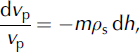
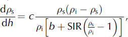
The step curves in Figure 1a-c show measured depth-density profiles at three Canadian Arctic ice-core sites: Agassiz, Devon and Penny Ice Caps. Position, elevation, 10 m firn temperature, mean annual accumulation rate and melt percentage (PC = SIR/b) at the sites are listed in Table 1. As an example, the observed depth melt percentage profile from the Agassiz Ice Cap site is also shown as a step curve to the left in Figure 1a. Model calculated depth-density profiles corresponding to different melt percentages are shown as smooth curves. A surface snow density ρs0 = 350kgm–3 was used at all sites.
Depth-density profiles at three Canadian Arctic ice-core sites: (a) Agassiz Ice Cap; (b) Devon Ice Cap; and (c) Penny Ice Cap. Measured profiles are shown as step curves. The observed depth melt percentage profile from the Agassiz Ice Cap site is also shown as a step curve to the left in (a). Model calculated depth-density profiles corresponding to different melt percentages (PC = SIR/b) are shown as smooth curves using a surface snow density of 350 kgm-3. Thin full curves correspond to calculations with PC = 0%. In (a) and (b), the heavy full curve and the thin dashed curve correspond to PC = 10% and PC = 20%, respectively. In (c), the heavy full curve and the thin dashed curve correspond to PC = 40% and PC = 60% respectively. The heavy dashed curve in (c) is the depth-density profile obtained with the HL model using a surface snow density ρs0 = 486 kg m–3 equal to the mean density of a surface layer with a 40% content of ice lenses.
Canadian Arctic ice-core sites
At all three sites, the depth-density profile corresponding to PC = 0 generally underestimates the observed densities. For the Agassiz and Devon Ice Cap records, the profile corresponding to PC =10% gives a reasonable fit, whereas the profile corresponding to PC = 20% generally overestimates the densities. For the Penny Ice Cap record, the calculated profile corresponding to PC = 40% gives, in general, a close fit, whereas the profile corresponding to PC = 60% overestimates the densities. Measured melt percentages agree with these findings. In the uppermost 30 m of the Agassiz Ice Cap record, the average measured PC is 5-10% (see Fig. 1a). Similar melt percentages were measured in the ice core from Devon Ice Cap (Reference Fisher and KoernerFisher and Koerner, 1994), whereas the melt percentage at the Penny Ice Cap site is on the order of 40% (Reference FisherFisher and others, 1998), in agreement with the melt percentages suggested by the modelled depth–density profiles.
4. Greenland Ice Sheet
Observations and model studies of firn densification indicate that the maximum rate of change of surface elevation due to time-dependent density changes is a few centimetres per year in the dry-snow zone of central Greenland (Reference Arthern and WinghamArthern and Wingham, 1998; Reference CuffeyCuffey, 2001). Much larger surface-elevation changes, without corresponding changes in mass, may occur in the percolation and wet-snow zones of the ice sheet. Here, a temperature change will change the amount of surface melting and subsequent refreezing of meltwater as ice lenses or superimposed ice. The resulting density change causes a change in surface elevation that may reach values of 10-20 cm a-1 (Reference Braithwaite, Laternser and PfefferBraithwaite and others, 1994). If the temperature change persists, the surface elevation will continue to change, but at a decreasing rate, asymptotically approaching a level determined by a new, adjusted depth-density profile. Hence, a change of surface elevation does not necessarily mean that the ice-sheet mass has changed. Part of the elevation change, or all of it, may be due to a change in surface layer density (e.g. caused by a change in the amount of refrozen meltwater).
The densification model is very suitable for studying the elevation change of a glacier or ice sheet due to temperature-driven density changes. As previously mentioned, input parameters to the model are mean annual mass balance b, mean annual surface temperature T, surface snow density ρs0, and ice-lens content SIR. For the Greenland ice sheet, the present spatial distributions of b and Tare pretty well known (e.g. Reference OhmuraOhmura, 1987; Reference Calanca, Gilgen, Ekholm and OhmuraCalanca and others, 2000; Reference Steffen and BoxSteffen and Box, 2001), whereas information on surface density ρs0 and ice-lens content SIR is more restricted. In this section, we describe a method for calculating SIR and derive a parameterization of ρs0 based on Greenland data.
4.1. Melting/refreezing model
The annual melt rate depends on the energy balance at the glacier surface, i.e. on the radiation budget and the turbulent heat transfer between the surface and the atmosphere. Instead of dealing with the rather complicated physical processes entering the energy balance at the glacier surface, snow- and ice-melt calculations are often based on an empirically established linear relationship between melt rate and positive degree-days (PDDs; e.g. Reference BraithwaiteBraithwaite, 1995; Reference HockHock, 2003). Reference ReehReeh (1991) used this method to derive the distribution of surface melt rate and runoff from the Greenland ice sheet. For present climate conditions, more sophisticated models − be they degree-day models (e.g. Reference Janssens and HuybrechtsJanssens and Huybrechts, 2000) or energy-balance models (e.g. Reference Van de WalVan de Wal, 1996) − generally give melt rates and runoff similar to those given by the simple degree-day model presented by Reference ReehReeh (1991). Hence, the simple approach will be used in this work.
Input to the model are parameterizations of mean annual air temperature T MA, mean July air temperature TMJ for the standard decade 1951-60 (Reference ReehReeh (1991) based on Reference OhmuraOhmura (1987)) and specific annual accumulation rate (Reference Calanca, Gilgen, Ekholm and OhmuraCalanca and others, 2000). PDDs are calculated from T MA , T MJ and a stochastic term T R accounting for temperature deviations from the average annual cycle and also accounting for the daily temperature cycle. T R is assumed to be normally distributed with standard deviation σ , and is centred on the curve representing the average annual temperature cycle. Snow, if present, is melted first. The meltwater is supposed to percolate into the snowpack and refreeze as ice lenses or superimposed ice. Runoff does not begin before the amount of refrozen meltwater exceeds a given fraction, PMAX, of the annual snow accumulation. Next, the superimposed ice is melted, and finally glacier ice is melted. Depending on the melt potential, i.e. the PDDs, we may have different surface conditions at the end of a melt season:
1. A surface snow layer (positive specific net balance) in which a smaller or larger fraction of the annual snow accumulation has been transformed into ice lenses, SIR.
2. A superimposed ice layer (positive specific net balance) if the total annual snow accumulation has been transformed into superimposed ice, of which a fraction, SIR, however, has survived subsequent melting.
3. A glacier ice surface (negative specific net balance) if the total annual snow accumulation has been transformed into superimposed ice that afterwards has been removed completely by melting and runoff.
The reader is referred to Reference ReehReeh (1991) for details on the calculation of PDD and SIR.
As far as the study of depth-density profiles is concerned, only case (1) above is of interest. In the present study, degree-day factors for snow- and ice melt are set to 0.003 and 0.007 m K–1 d–1 w.e., respectively, σ = 4.2K, and PMAX = 0.6 (Reference ReehReeh, 1991; Reference Janssens and HuybrechtsJanssens and Huybrechts, 2000).
4.2. Distribution of surface snow density in Greenland
The surface snow density ρs0 to be used in the densification model is the extrapolation to zero depth of the density-depth profile above the critical density of 550 kgm–3 (see Reference Herron and LangwayHerron and Langway, 1980). This density may not be identical with the average density over the first 1 or 2 m of snow, where the densification occurs much more rapidly than immediately beneath (Reference CuffeyCuffey, 2001). Moreover, in the present model, which deals with snow and firn containing ice lenses, ρs0 represents the density of only the snow fraction of the surface layer. A possible contribution to the surface-layer density from ice lenses is not included.
Near-surface depth-density data from stations along a traverse on the Greenland ice sheet from 77˚ N to 70˚ N were published by Reference BensonBenson (1962, appendix C). Geographical coordinates, 10m snow temperature and annual accumulation rate for the stations are listed by Reference Mock and WeeksMock and Weeks (1965, appendix A). Reference Braithwaite, Laternser and PfefferBraithwaite and others (1994) present density-depth data, 10 m temperature and accumulation rate data from the lower-accumulation area of the West Greenland ice sheet at 69.7˚ N and even give estimates of SIR. Additional depth-density data have been measured during the Greenland Ice Sheet Project 2 (GISP2), the Greenland Icecore Project (GRIP) and the Program for Arctic Regional Climate Assessment (PARCA; Reference Mosley-ThompsonMosley-Thompson and others, 2001).
Instead of deriving ρs0 from the near-surface part of the depth-density profiles by extrapolation (see above), ρs0 is determined so that the load at 5 m depth (P), as calculated from the model given by Equations (4), (7), (9) and (10), fits the corresponding load derived from the measured depth-density profiles. In order to apply this method, connected values of load P, mean annual firn temperature Tf, annual snow accumulation b and ice-lens content SIR must be available. At most locations, SIR has not been observed and, consequently, must be estimated as described in section 4.1.
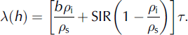
The derived surface snow densities, ρs0, are plotted vs firn temperature in Figure 2. Except for a few outliers, the densities are well represented by a least-squares quadratic fit, explaining >80% of the variance:
Surface snow density on the Greenland ice sheet vs 10 m firn temperature. Data sources: filled circles: Reference BensonBenson (1962); open triangles: Reference Braithwaite, Laternser and PfefferBraithwaite and others (1994); crosses: Reference Mosley-ThompsonMosley-Thompson and others (2001); filled triangles: H.B. Clausen (personal communication, 2004). Full curve represents a least-squares quadratic fit. Points within the thin closed curve are omitted from the fitting procedure (see text for explanation).
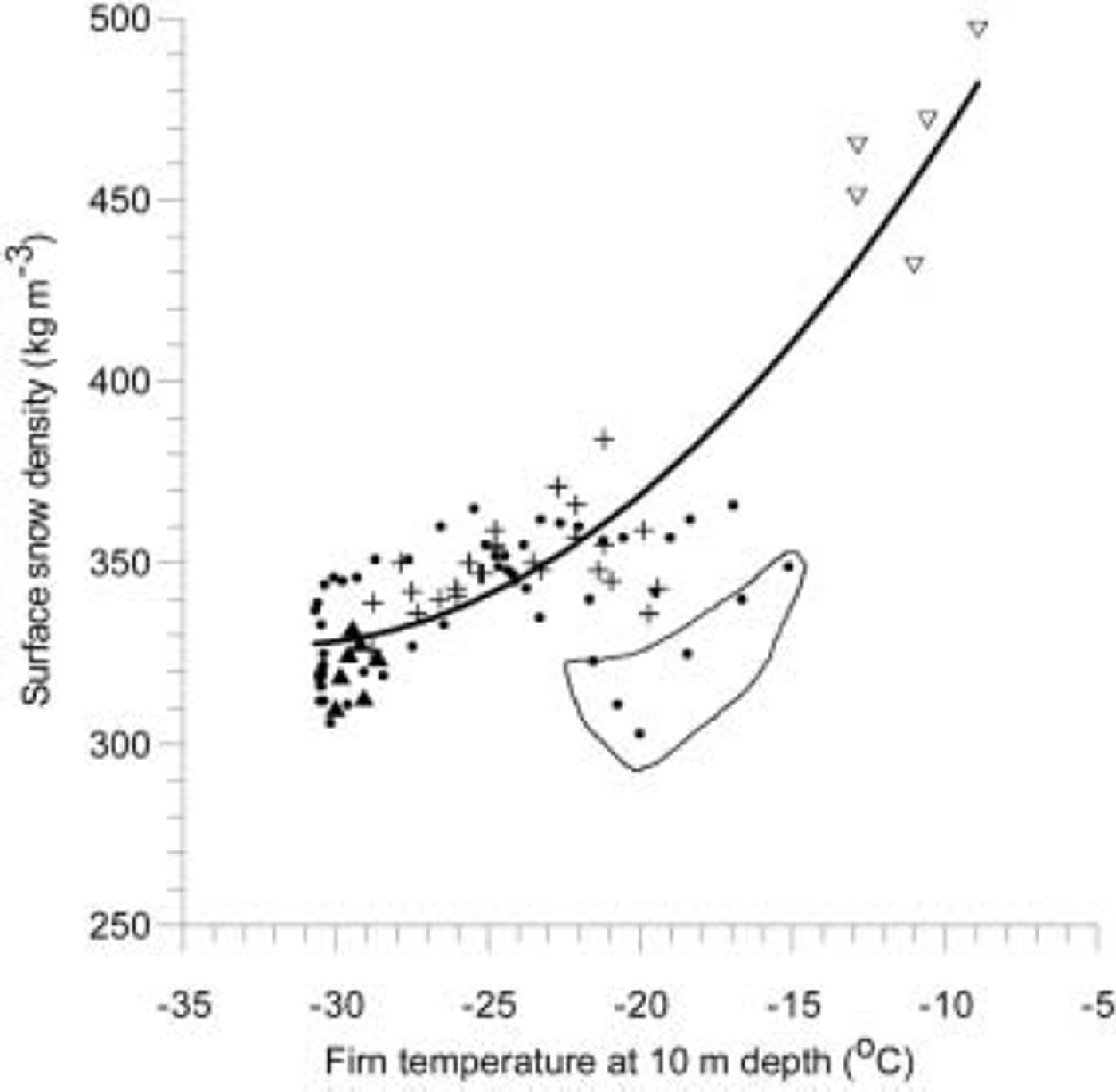
The outliers are all located in a small region in northwest Greenland. Inspection of the corresponding depth-density plots (Reference BensonBenson, 1962, appendix C) suggests that the derived low densities are caused by a single year with anomalously low snow density at these stations. We have chosen to exclude these points from the least-squares fitting procedure.
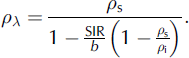
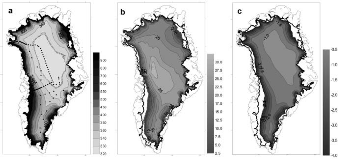
Figure 3a shows the distribution of surface layer density in Greenland, ρλ0, as calculated from Equation (4), with b, SIR and ρs0 derived as described above. ρλ0 represents the density of the surface layer including SIR, the contribution from ice lenses. The locations of sites with density observations used to derive Equation (11) are shown in the figure as dots.
Greenland ice sheet. (a) Calculated surface layer density (kg m–3). Dots show position of density observations. (b) Total air content (m) of the firn expressed as H air = H – H ieq, where H is ice thickness and H ieq is ice equivalent thickness. (c) Asymptotic value of surface lowering (m) for a step increase in the mean surface temperature of 1 K.
4.3. Asymptotic height response to increased melting-refreezing rate
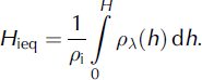
The asymptotic height response of the ice sheet to a temperature change is most conveniently expressed in terms of changes in the total air volume of the firn expressed as H air =H-Hieq, where H is ice thickness and Hieq is ice equivalent thickness defined as
The calculated distribution in Greenland of H air is shown in Figure 3b, corresponding to the ice-sheet climate for the standard decade 1951–60 (Reference OhmuraOhmura, 1987). Figure 3c shows the calculated asymptotic value of the change in H air for an increase in mean annual air temperature of 1 K assuming unchanged accumulation rate. The change in H air is equal to the surface lowering that will eventually result for a step change in temperature of 1 K if the change is maintained over a sufficiently long period of time. The rate of change of surface elevation is relatively high immediately after the onset of the temperature change but decreases asymptotically to zero with time.
5. Discussion and Conclusions
The densification model developed in this paper, which specifically accounts for the influence of ice-lens content in the firn, fits observed depth-density profiles from Canadian Arctic ice-core sites reasonably well. In particular, the good fit of the model to the Penny Ice Cap depth-density record, with a measured melt percentage as high as 40%, demonstrates the good performance of the model (Fig. 1c). An attempt at fitting the HL model to the Penny Ice Cap depth-density profile by using a surface snow density ρs0 = 486 kg m–3, i.e. a density equal to the mean density of a surface layer with a 40% content of ice lenses, was not successful. The derived depth-density profile greatly underestimates the measured densities (see Fig. 1c), demonstrating that it is necessary to consider the snow and ice fractions of the firn pack separately.
Another advantage of the new model as compared to the HL model is the possibility of using the model to study temperature-driven changes of depth-density profiles in percolation and wet-snow zones of glaciers and ice sheets, and the associated surface-elevation changes. In this paper, this potential of the model is demonstrated by calculating the asymptotic height response of the ice sheet that will result from changes in the depth-density profile for a 1 K step increase of temperature. It is shown that the permanent lowering of the surface for this case varies from <1 m in the dry-snow zone of central Greenland to >3.5 m in the lower part of the percolation zone.
It is important to stress that these surface elevation changes reflect a volume change of the ice sheet with no corresponding change of mass, in other words a volume change that does not influence global sea level. Of course, a temperature increase will also result in increased mass loss from the ice sheet (assuming unchanged accumulation rate) due to increased ice melt and runoff (maybe also due to increased iceberg calving). However, using the melting/ refreezing model, Reference ReehReeh (2004) shows that, for the total Greenland ice sheet, the first-year volume loss caused by a 1 K increase in surface temperature is 128 km3 a–1 ice equivalent, whereas the increased mass loss by runoff is only 96 km3 a–1 ice equivalent. In other words, only about 75% of the first-year volume change for a 1 K warming over the ice sheet actually represents a change of mass.
Space- and airborne radar and laser altimetry has over the last few decades immensely improved our capability to measure changing surface elevation of the Greenland and Antarctic ice sheets and other large land-ice masses. With ICESat (Ice, Cloud and land Elevation Satellite) launched by NASA in 2003 and CryoSat launched by the European Space Agency at the beginning of 2005, new, improved altimetry data will become available.
Previous studies dealing with interpretation of repeated altimetry observations of ice sheets have emphasized the need for simultaneous measurement of snow accumulation in order to ‘clean’ the records for variability of snow accumulation, so that the long-term trend of surface elevation can be extracted (Reference McConnellMcConnell and others, 2000; Reference Zwally and LiZwally and Li, 2002). The difference, demonstrated by the present study, between ice-sheet volume and mass change caused by temperature-driven density changes, shows that it is equally important to simultaneously record ice-lens formation or, alternatively, measure temperature, enabling estimation of ice-lens formation.
We conclude that a prerequisite for proper interpretation of observations of ice-sheet surface elevation change, in terms of changing ice mass and hence changing global sea level, is that observed elevation changes can be continuously corrected for variations of accumulation rate and surface layer density. Development of improved methods for deriving accumulation rate and melting/refreezing rates from satellite observations (Reference Drinkwater, Long and BinghamDrinkwater and others, 2001; Reference Smith, Sheng, Forster, Steffen, Frey and AlsdorfSmith and others, 2003), combined with continued operation of networks such as the Greenland Climate Network (Reference Steffen and BoxSteffen and Box, 2001) enabling modelling of accumulation rate and surface layer density changes, seem to be feasible ways to achieve this goal.


