


1 Introduction
The 2 μm laser, operating in the eye-safe wavelength range, has broad applications across various fields. For instance, it can be used in meteorology due to its wavelength within atmospheric transmission windows[ Reference Li, Niu, Wu, Yu and Ma1]. In surgery, the 2 μm laser enables precise tissue incision with minimal thermal damage, owing to strong water absorption in the body[ Reference Cao, Zhao, Liu, Xia, Wang, Yan and Wang2]. Moreover, it serves as an essential pump source for mid-infrared optical parametric oscillators (MIR-OPOs)[ Reference Piotrowski, Bogas-Droy, Spindler, Bigotta and Hildenbrand-Dhollande3]. High-energy 2 μm lasers operating at kilohertz repetition rates with pulse energies ranging from a few hundred millijoules to several joules also have potential applications in extreme ultraviolet (EUV) radiation generation[ Reference Behnke, Schupp, Bouza, Bayraktar, Mazzotta, Meijer, Sheil, Witte, Ubachs, Hoekstra and Versolato4, Reference Schupp, Behnke, Bouza, Mazzotta, Mostafa, Lassise, Poirier, Sheil, Bayraktar, Ubachs, Hoekstra and Versolato5]. Currently, EUV radiation is mainly generated by laser-produced plasma (LPP) using CO2 lasers to irradiate tin droplets[ Reference Lin, Chen, Wei, Yang and Leng6]. With comparable EUV excitation efficiency and higher electro-optical conversion efficiency than traditional 10.6 μm CO2 lasers, 2 μm lasers show strong potential as all-solid-state EUV driver sources[ Reference Siders, Bayramian, Erlandson, Galvin, Langer, Sistrunk and Spinka7, Reference Siders, Bayramian, Erlandson, Galvin, Langer, Sistrunk and Spinka8].
There are two main approaches to generating 2 μm lasers. One involves using an optical parametric oscillator (OPO) with nonlinear crystals (e.g., potassium titanyl phosphate (KTP)), which benefits from a compact structure and the availability of mature commercial 1 μm pump sources. However, its beam quality typically degrades owing to the walk-off effect[ Reference Nandy, Ye, Kumar and Ebrahim-Zadeh9, Reference Liu, Song, Peng, Li, Long, Sun, Shen, Liu, Zhu, Leng and Xu10]. Another approach relies on stimulated emission from rare-earth ions such as Tm3+ or Ho3+. Tm-doped media can be directly pumped with laser diodes (LDs) for 2 μm emission[ Reference Noach, Bach, Adgo, Garcia and Agranat11], but achieving high-average-power output is rather difficult owing to strong thermal effects, since a high Tm3+ doping is usually required to enhance quantum efficiency via cross-relaxation[ Reference Chen, Li, Wang, Yang, Yu, Yin, Zhu, Ding, Wang and Lu12– Reference Yu, Pan, Pan, Chu, Chen and Li14]. In contrast, Ho-doped media can be in-band pumped by 1.9 μm Tm lasers, achieving both high pulse energy and high average power owing to a lower quantum defect and a larger emission cross-section (more than five times greater than Tm-doped media)[ Reference Zhao, Zhang, Zhu, Liu, Jiang, Dou, Yang and Hou15– Reference Payne, Chase, Smith, Kway and Krupke17]. In addition, this scheme can distribute the heat load mainly to the pump modules (i.e., Tm lasers), simplifying thermal management.
Holmium-doped yttrium aluminum garnet (Ho:YAG) is commonly used in high-power Ho-doped lasers owing to its excellent mechanical properties and mature crystal fabrication techniques[ Reference Eichhorn18, Reference Wang, Tong, Zheng, Du, Zhao and Wang19]. In 2018, Zhao et al. [ Reference Zhao, Yao, Qian, Liu, Chen, Wang, Dai and Duan20] demonstrated a Ho:YAG master oscillator power amplifier (MOPA) system delivering 231 W of average power at 10 kHz, pumped by a thulium-doped yttrium lithium fluoride (Tm:YLF) laser. In 2021, Liu et al. [ Reference Liu, Mi, Yang, Wei, Li, Yao, Yang, Dai, Duan, Tian and Ju21] reported a 334 W Ho:YAG MOPA system at 20 kHz and in 2022, their group further increased the power to 450 W at 40 kHz[ Reference Mi, Tang, Wei, Yao, Li, Yang, Dai and Duan22]. Although these systems deliver high average powers at tens of kHz, their pulse energies are relatively low (typically tens of millijoules), which limits their suitability for applications requiring high-energy pulsed lasers. To date, very few studies have simultaneously achieved both high power and high pulse energy, owing to the trade-off between amplifier gain and optical damage. Achieving high pulse energy requires increasing the beam size and crystal aperture to prevent component damage, which reduces gain and complicates thermal management. In 2019, Qian et al. [ Reference Qian, Yao, Ju, Duan, Zhao, Dai and Wang23] demonstrated a Ho:YAG MOPA system with a pulse energy of 110.4 mJ and an average power of 110.4 W at 1 kHz. However, the extraction efficiency of each amplifier stage was below 19%; thus, further scaling up the power/energy by cascading more amplifier stages becomes challenging.
In comparison, Ho:YLF (YLiF4) is a promising medium for high-energy 2 μm lasers owing to its large emission cross-section (1.8 × 10⁻²⁰ cm² at 2050 nm, π-polarization), large absorption cross-section (1.2 × 10⁻²⁰ cm² at 2050 nm, π-polarization)[ Reference Payne, Chase, Smith, Kway and Krupke17], long fluorescence lifetime (~14 ms)[ Reference Walsh, Barnes and Di Bartolo24] and low energy-transfer upconversion (ETU) loss[ Reference Barnes, Walsh and Filer25], all of which contribute to its excellent energy storage and extraction capabilities. Furthermore, the negative thermo-optic coefficient of the YLF host can partially compensate for positive thermal lensing caused by end-face expansion at high pump powers[ Reference Walsh, Grew and Barnes26, Reference Schellhorn27], enhancing its power scalability. In 2013, Fonnum et al. [ Reference Fonnum, Lippert and Haakestad28] demonstrated a Q-switched cryogenic Ho:YLF laser delivering 550 mJ pulse energy pumped by a Tm:fiber laser at 1 Hz, which remains the highest-energy Ho:YLF laser reported. At repetition rates of several hundred Hz, the highest reported 2 μm pulse energy from Ho:YLF lasers is 170 mJ (17 W average power)[ Reference Alexey, Darrell, Arlee, Thomas and Marc29]. However, at kHz repetition rates, the highest reported pulse energy remains below 40 mJ (average power of <40 W)[ Reference Dergachev, Moulton and Drake30]. Over the past two decades, reports that simultaneously improved the pulse energy and average power of Ho:YLF lasers in this regime are absent.
In this paper, we present a high-power, high-energy 2.05 μm Ho:YLF MOPA system employing three-stage rod amplifiers pumped by Tm:fiber lasers. The system achieves a maximum output power of 280 W with a 14.5 ns pulse width at 1 kHz, representing, to the best of our knowledge, the highest pulse energy for 2 μm lasers at kHz repetition rates. In addition, a slice model of a quasi-three-level laser amplifier, combined with a thermal analysis model, was developed to predict the power-scaling behavior of multi-stage Ho:YLF rod amplifiers.
2 Experimental setup
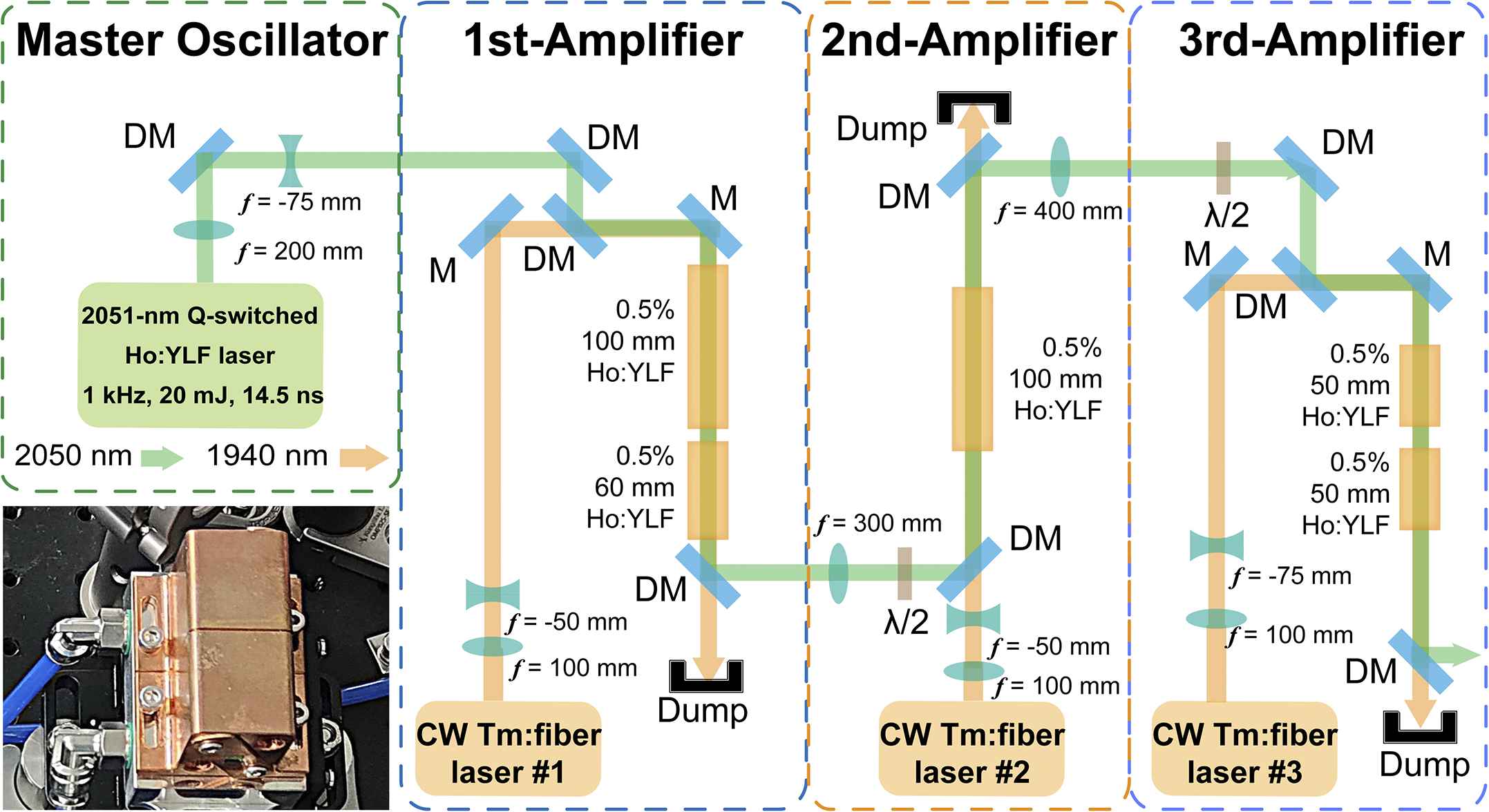
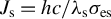
Figure 1 shows the experimental setup of the Ho:YLF MOPA system, which consists of a master oscillator and three amplifier stages. The master oscillator is a self-developed Q-switched Ho:YLF laser operating at a central wavelength of 2051.3 nm, delivering a maximum output power of 20.5 W at a 1 kHz repetition rate. The laser beam quality is characterized by using a high-sensitivity pyroelectric camera (Pyrocam IV, Ophir). Figure 2(a) presents the measured beam quality of the master oscillator, with M² values of 1.32 and 1.17 in the horizontal and vertical directions, respectively. The insets show the far-field Gaussian beam profile and the spectrum of the seed laser, confirming its high beam quality. Figures 2(b) and 2(c) display a stable 1 kHz pulse train and a typical pulse profile with a width of 14.5 ns, indicating excellent temporal stability of the seed laser. Three continuous-wave (CW) Tm:fiber lasers (RFL-CW200-1940, Raycus) at 1940 nm, with maximum powers of 199, 211 and 215 W, are used in the first-, second- and third-stage amplifiers, respectively. All three Tm:fiber pump lasers operate in an unpolarized state and exhibit excellent beam quality (M 2 < 1.3) and power stabilities. The root mean square (RMS) power fluctuations at their maximum output powers are 0.27%, 0.22% and 0.30%, respectively, as shown in Figure 2(d). M is a reflective mirror with high-reflection (HR) coating from 1900 to 2100 nm. DM is a dichroic mirror anti-reflection (AR) coated at 1940 nm and HR coated at 2050 nm. The coating damage threshold of all mirrors and crystals provided by the suppliers is 10 J/cm2. In the first-stage amplifier, two Ho:YLF crystals (0.5% (atomic fraction), 100 and 60 mm) are placed orthogonally to enhance pump absorption. The π-axis of the first crystal is oriented vertically. The pump and seed beam radii at the crystal center are 750 and 720 μm, respectively. In the second-stage amplifier, a 100 mm Ho:YLF crystal (0.5%) is used with its π-axis oriented horizontally to compensate for the thermally induced astigmatism from the first-stage amplifier and to improve the beam circularity. The pump beam radius is 750 μm, and the seed beam radii are 1.2 mm (x-axis) and 740 μm (y-axis) at the crystal center. In the third-stage amplifier, two 50 mm Ho:YLF crystals (0.5%) are placed orthogonally, with the π-axis of the first crystal oriented vertically. The pump beam radius is 1.1 mm, and the seed beam radii are 900 μm (x-axis) and 1.4 mm (y-axis) at the crystal center. To maximize gain, the polarization states of the seed laser are set to s-, p- and s-polarizations in the first-, second- and third-stage amplifiers, respectively, using half-wave plates between the stages. All Ho:YLF crystals are mounted in water-immersed heat sinks, as shown in the inset of Figure 1, with their side surfaces in direct contact with circulating water, maintaining a cooling temperature of 10°C. Optical dumps are used to collect unabsorbed pump light from the crystals.
Experimental setup of the Ho:YLF MOPA system. M, reflector; DM, dichroic mirror. Inset: photograph of the water-immersed heat sink.
(a) Laser beam quality of the Ho:YLF oscillator at the output power of 20.5 W, (b) pulse train and (c) pulse profile. (d) Power stabilities of Tm:fiber pump lasers.

3 Results and discussion
3.1 Laser amplification properties
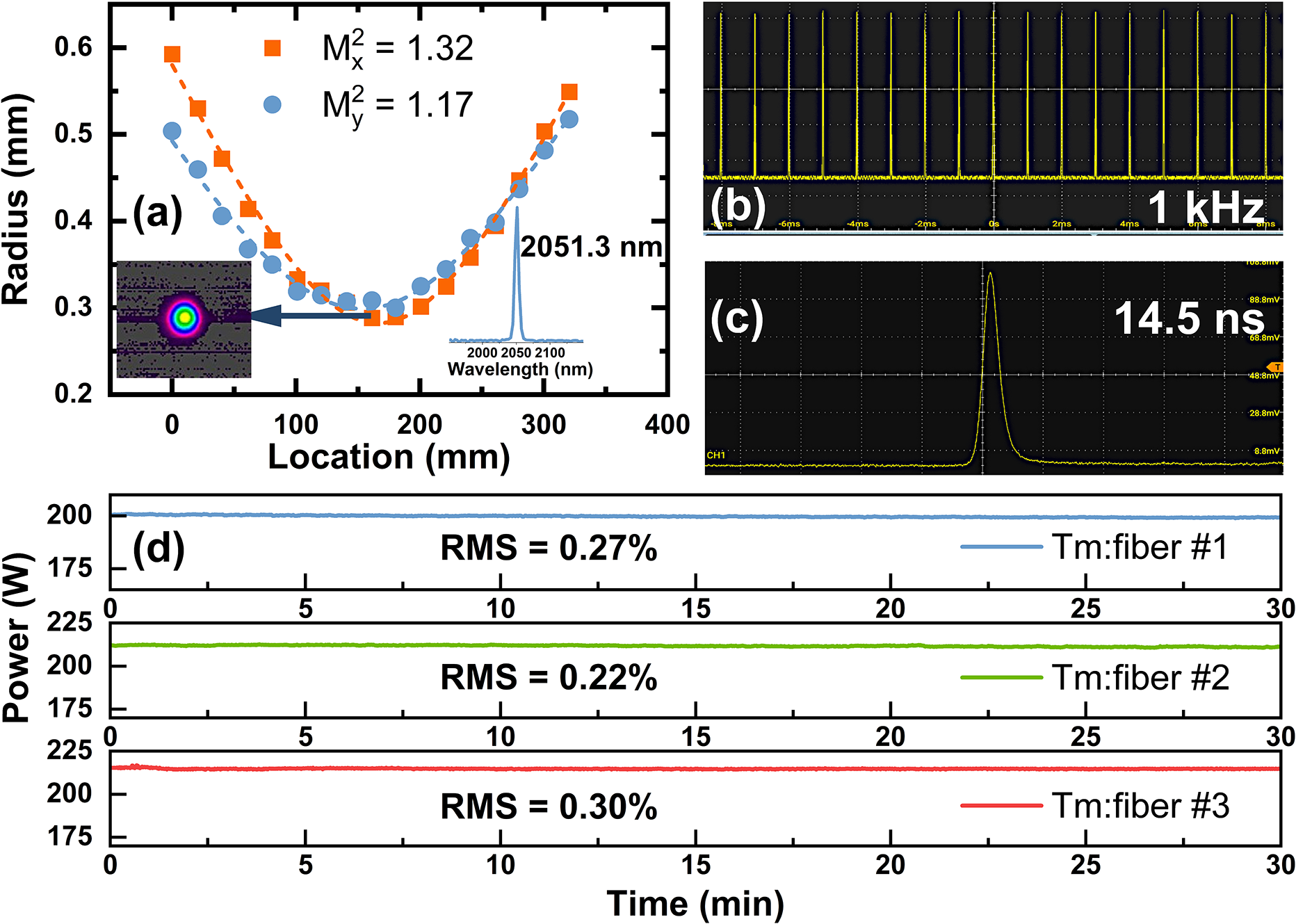
Figure 3 shows the output power of the first-stage amplifier versus the incident pump power. Initially, only a 100 mm Ho:YLF crystal was used, yielding a maximum output power of 94.8 W at 196.6 W of incident pump power, with a slope efficiency of 49.8% and an extraction efficiency of 40.2%. However, about 45.5 W of pump power remained unabsorbed at this point. By adding a 60 mm Ho:YLF crystal in series, oriented orthogonally, the output power increased to 110.1 W, with a higher slope efficiency (59.1%) and a higher extraction efficiency (46.1%). Figure 4 shows the beam quality of the first-stage amplifier at maximum output. The beam quality factors M 2 are 1.42 (x-axis) and 1.13 (y-axis) when singly using one 100 mm Ho:YLF crystal, with the far-field beam profile (inset of Figure 4(a)) showing a vertically elliptical spot. This is due to the anisotropic nature of Ho:YLF, which causes unequal thermal focal lengths in the x- and y-directions, leading to astigmatism under high pump power. Adding the second orthogonally oriented 60 mm Ho:YLF crystal reduced the ellipticity, improving the M² values to 1.36 (x-axis) and 1.11 (y-axis), as shown in Figure 4(b).
Output powers of the first-stage amplifier using the different combinations of Ho:YLF crystals with respect to the incident power of the Tm:fiber laser.

Laser beam quality of the first-stage amplifier with the utilization of (a) a 100 mm Ho:YLF crystal and (b) combination of 100 and 60 mm Ho:YLF crystals.
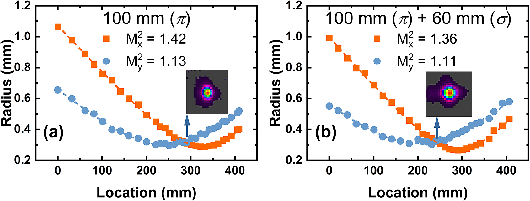
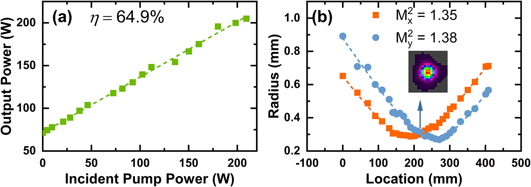
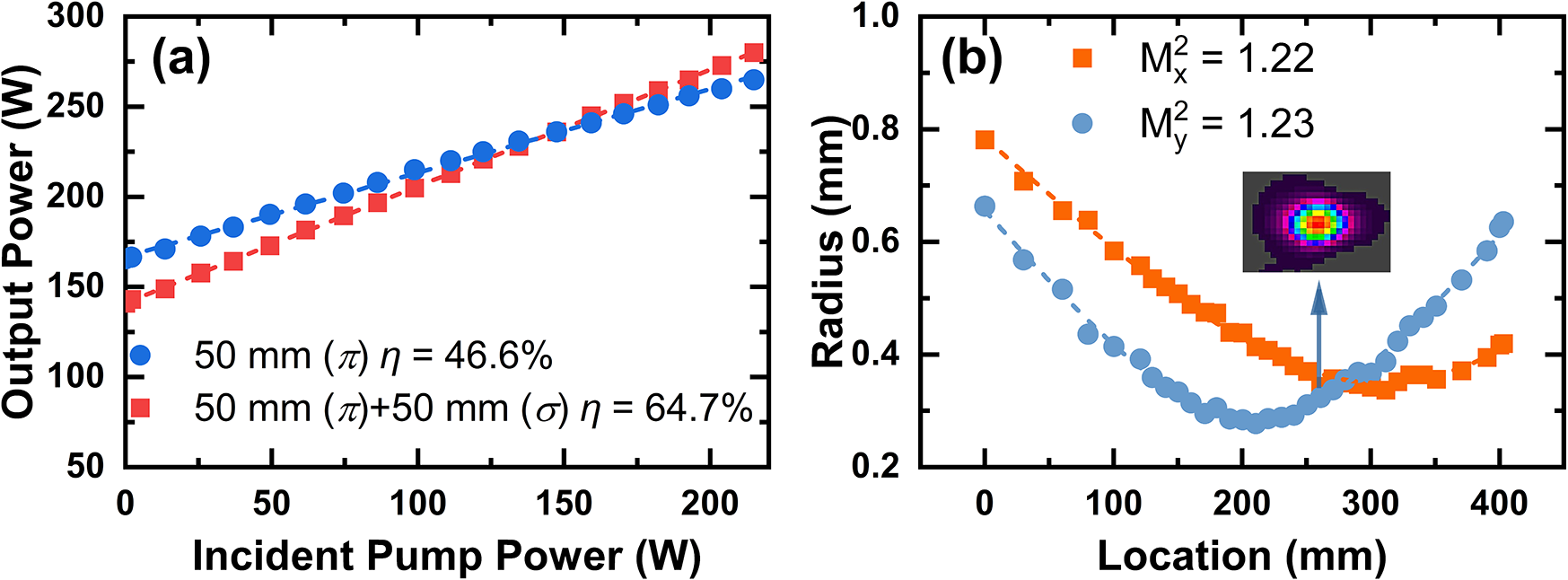
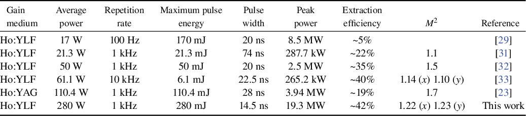
Figure 5 presents the performance of the second-stage amplifier. As shown in Figure 5(a), the maximum average output power is 205 W, with a slope efficiency of 64.9% and an extraction efficiency of 45.0%. Note that only one Ho:YLF crystal is used in this stage owing to sufficient pump absorption; adding another orthogonally oriented crystal decreased the output power. Figure 5(b) shows the beam quality at this stage, with M² values of 1.35 and 1.38 in the x- and y-directions, respectively. The inset shows a more circular far-field profile, attributed to the orthogonal placement of the Ho:YLF crystal with respect to the first crystal used in the first amplifier stage, which passively compensates the first stage’s thermal astigmatism. Figure 6(a) shows the third-stage amplifier performance. Using a single 50 mm crystal, a maximum output power of 265 W was achieved with a slope efficiency of 46.6% and an extraction efficiency of 27.9%. With two 50 mm crystals in series, the output power reached 280 W with a slope efficiency of 64.7% and an extraction efficiency of 34.9%. The beam quality of the third-stage amplifier, measured using a 400 mm focal length lens positioned 455 mm from the center of the second crystal, is shown in Figure 6(b). The laser exhibits excellent beam quality with M² values of 1.22 and 1.23 in the horizontal and vertical directions, respectively. The inset shows a near-perfect TEM00 Gaussian profile. Notably, the beam quality does not degrade and even slightly improves after the three-stage amplification. This improvement is attributed to the orthogonal crystal orientations within and between the amplifier stages. Figure 7 presents the power stability of the three amplifier stages over 30 min. The RMS stabilities at maximum output power were 0.38%, 0.18% and 0.50% for the first, second and third stages, respectively. Note that the power stability of the second-stage amplifier is significantly better than that of the other two stages. This may be attributed to the use of only a single Ho:YLF crystal in this stage, which has fewer optical interfaces and a shorter pump–seed interaction length, resulting in better mode matching and thus better power stability. During the experiments, we did not observe any amplified spontaneous emission (ASE) or parasitic oscillations that affect the amplification performance, which may be due to the adoption of AR coating on crystal end facets, crystal tilting combined with spatial filtering and the use of the reabsorption characteristic of Ho:YLF to suppress longitudinal and transverse ASE and parasitic oscillations. Table 1 compares the performance of the presented system with other state-of-the-art 2 μm Ho-doped MOPA systems. This work significantly improves the average output power of nanosecond Ho:YLF pulsed lasers, reaching over 280 W – an order of magnitude higher than previous results. Simultaneously, it achieves the highest reported pulse energy (~280 mJ) for a 2 μm laser operating at a kHz repetition rate, demonstrating a 2 μm source with both high average power and high pulse energy.
Laser performance of the second-stage amplifier: (a) output powers with respect to the incident pump powers; (b) measured laser beam quality after second-stage amplification.
Laser performance of the third-stage amplifier: (a) output powers with respect to the incident pump powers; (b) measured laser beam quality after third-stage amplification.
Maximum average output power of three amplifiers measured over 30 min.

Comparison of state-of-the-art 2 μm Ho-doped MOPA systems.
3.2 Theoretical modeling and analysis
High-power and high-energy 2 μm lasers are considered strong candidates for next-generation EUV driver sources. To achieve high EUV conversion efficiency and yield, the 2 μm pulse energy theoretically needs to reach the joule level at repetition rates of several kHz[ Reference Siders, Erlandson, Galvin, Frank, Langer, Reagan, Scott, Sistrunk and Spinka34]. However, in MOPA systems based on rod geometry, the output power and energy of each stage are strongly limited by laser-induced and thermally induced damages. As the number of amplifier stages increases (i.e., as laser pulse energy increases), the beam size must also be expanded to avoid pulse-induced damage. This increase in beam size reduces the laser fluence, which lowers the extraction efficiency of the amplifiers and leads to greater reabsorption losses for quasi-three-level systems such as Ho:YLF. Simultaneously, the clear aperture of the gain medium must also be increased to accommodate the larger beam size; however, this comes at the cost of reduced heat dissipation efficiency in side-cooled rod geometries. Consequently, the maximum allowable pump intensity – and therefore the amplifier gain per stage – decrease. Based on this analysis, we can expect the extraction efficiency per stage, as well as the overall optical conversion efficiency of the MOPA system, to gradually decline as more amplifier stages are added. To address these challenges, an end-pumped quasi-three-level laser amplifier model must be developed to theoretically investigate the key factors affecting amplification performance and to explore potential optimization strategies for safe and efficient laser operation. Furthermore, such a simulation should estimate the power extraction limits of our Ho:YLF rod amplifiers and evaluate their power-scaling capability when extended to additional amplifier stages.
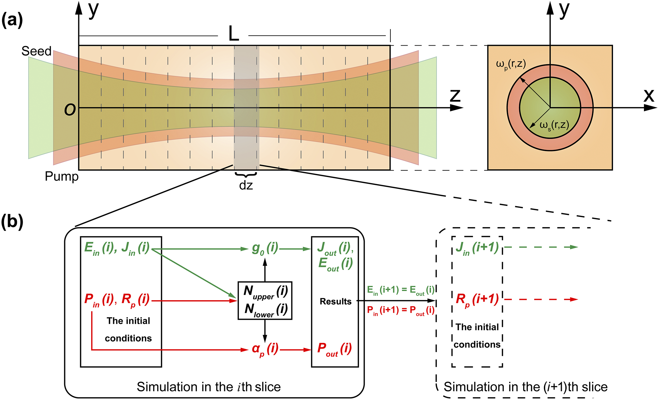
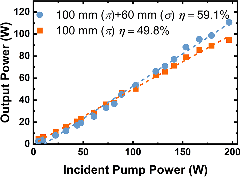
Figure 8(a) shows the slice model of an end-pumped Ho:YLF rod amplifier, specifically accounting for laser reabsorption and the Gaussian distribution of laser intensities, providing a more realistic depiction of gain variations within the crystal. Figure 8(b) conceptually illustrates the calculation logic in each slice of the crystal. Given the initial incident seed energy and pump power, the inverted population density in each slice can be calculated by solving the quasi-three-level rate equations. The amplified laser power and unabsorbed pump power after each slice are then computed using the Frantz–Nodvik equations and used as initial conditions for the next slice. The final output power and unutilized pump power of the amplifier can be obtained by iteratively applying this slice-based calculation along the crystal’s length, thereby determining the extraction efficiency per stage and the overall optical conversion efficiency of the system. The detailed theoretical derivations are provided in the Appendix, and the key parameters used in the simulations are summarized in Table 2.
(a) Slice model of the Ho:YLF rod amplifier. (b) Calculation logic in each slice of the crystal.
Key parameters used in the slice amplifier model.

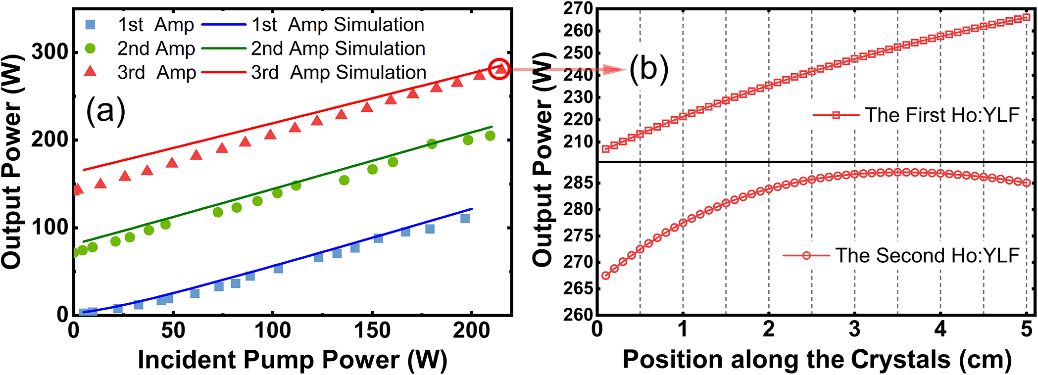
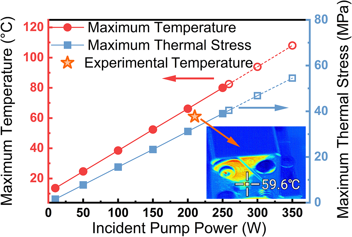
Figure 9(a) shows the simulated output powers compared with the experimental results for the three-stage amplifiers. The simulation results show good agreement with the experiments, validating that the model can reasonably reflect amplifier output performance. Subsequently, a detailed simulation was conducted to examine the evolution of average power along the Ho:YLF crystals in the third-stage amplifier, as shown in Figure 9(b). At a maximum incident pump power of 215 W, the average power continuously increases along the first Ho:YLF crystal, whereas in the second crystal, it initially rises and then decreases near the rear facet. This decline is attributed to the significantly depleted pump power toward the rear, resulting in insufficient population inversion to overcome intrinsic laser reabsorption. The simulated maximum output power is 287 W at the 3.6 cm position of the second Ho:YLF crystal, indicating that 8.6 cm is the optimal gain length for the third-stage amplifier. To further explore the power/energy scaling capability, the tolerable pump limit of the Ho:YLF crystal was evaluated using finite element simulations in COMSOL software. Figure 10 presents the simulated maximum temperature and thermal stress in the first Ho:YLF crystal of the third-stage amplifier as functions of the incident pump power. The star dot represents the maximum temperature on the front facet of the Ho:YLF crystal experimentally measured by an infrared thermal imager at the maximum pump power. The simulated temperature is slightly higher than the experimental result, indicating that the actual fractional thermal load is slightly lower than our prediction. However, it can overall conservatively reflect the heat generation behavior of the Ho:YLF crystal. Hollow dots represent data points exceeding the stress fracture limit of the YLF matrix (~40 MPa)[ Reference El-Agmy and Al-Hosiny36], which corresponds to a maximum tolerable pump power of 259 W. Under these conditions, a maximum output power of 311 W can be achieved at an optimal gain length of 9.1 cm, representing the estimated performance limit of the third-stage amplifier.
(a) Comparison of the simulated output powers and the experimental results of three-stage amplifiers. (b) Variation of simulated average power along two Ho:YLF crystals in the third-stage amplifier at the maximum output power.

Simulated maximum temperature and thermal stress of Ho:YLF in the third-stage amplifier as a function of incident pump power.

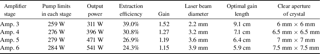
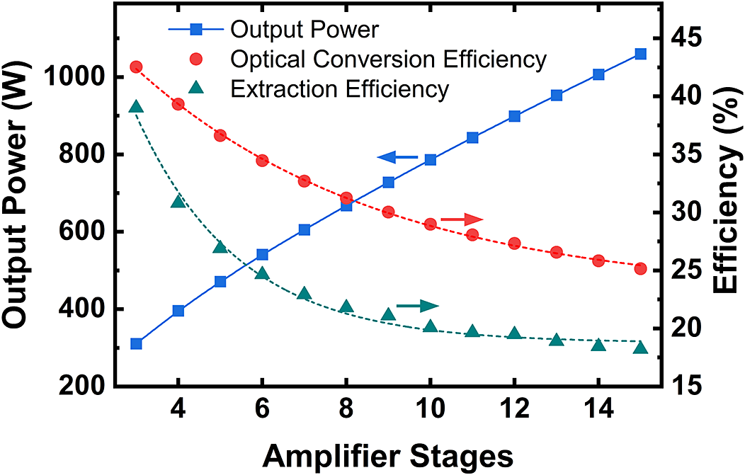
Using the same analytical approach, we extended the simulations to predict the performance limits of an end-pumped Ho:YLF MOPA system with additional amplifier stages. Table 3 summarizes simulation results for the third through sixth stages. The corresponding maximum output power, optical conversion efficiency and extraction efficiency of each stage are illustrated in Figure 11. As expected, increasing the number of amplifier stages leads to exponential declines in both optical conversion and extraction efficiency. Achieving joule-level pulse energy at a 1 kHz repetition rate would require more than 10 (~14) amplifier stages in a rod-based Ho:YLF MOPA system, with the overall optical conversion efficiency falling below 30%. In practical systems, effects such as negative thermal lensing reduce laser fluence, and beam astigmatism worsens mode matching, leading to even lower extraction efficiency. Therefore, when the extraction efficiency of a certain rod amplifier stage drops below 30%, we recommend transitioning to more efficient amplifier architectures – such as thin disks[ Reference Xu, Liu, Gao, Ou, Javed, He, Lu, Chen, Chen, Ouyang, Zhao, Wu, Guo, Zhou, Lue and Ruan37] or gas-cooled multi-slab amplifiers – to improve thermal management and increase the maximum tolerable pump intensity for higher output power.
Simulated output performance of multi-stage Ho:YLF rod amplifiers.
Simulated maximum output power, optical conversion efficiency and extraction efficiency for multi-stage Ho:YLF rod amplifiers.

4 Conclusion
In conclusion, we have developed a 2.05 μm Ho:YLF MOPA system with record-high average power and pulse energy based on a three-stage cascaded rod amplifier. A maximum output power of 280 W was achieved with a pulse width of 14.5 ns at a 1 kHz repetition rate, corresponding to a pulse energy of 280 mJ and a peak power of 19.3 MW – representing, to the best of our knowledge, the highest energy ever achieved for a 2 μm laser operating at a kHz repetition rate. A self-built 20.5-W Q-switched Ho:YLF laser was used as the seed source, followed by a three-stage amplifier. Through optimized crystal combinations, maximum output powers of 110.1, 205.0 and 280.0 W were achieved from the first, second and third stages, respectively, with extraction efficiencies of 46.1%, 45.0% and 34.9%. At maximum output, the Ho:YLF MOPA system demonstrated excellent beam quality (Mx ² = 1.22, My ² = 1.23) and stable performance, with an RMS power fluctuation of only 0.5% over a 30-min measurement. In addition, we proposed an end-pumped quasi-three-level amplifier model to predict and optimize the system’s performance and scaling behavior. This model enabled us to estimate the performance limits of rod-based Ho:YLF MOPA systems with additional amplifier stages. We hope this work offers valuable insights for designing high-power, high-energy 2 μm laser systems.
Appendix A: Slice model of the end-pumped Ho:YLF amplifier
An illustration of the Ho:YLF amplifier model is presented in Figure 8(a). In this model, the crystal was equally divided into numerous slices along the z-axis with a thickness of
 $\mathrm{d}z$
. The pump rate
$\mathrm{d}z$
. The pump rate
 ${R}_{\mathrm{p}}$
and small-signal gain
${R}_{\mathrm{p}}$
and small-signal gain
 ${g}_0$
can be determined independently in each slice by solving the quasi-three-level rate equations, which are expressed in Equations (1) and (2)[
Reference Schellhorn and Hirth38]:
${g}_0$
can be determined independently in each slice by solving the quasi-three-level rate equations, which are expressed in Equations (1) and (2)[
Reference Schellhorn and Hirth38]:
 $$\begin{align}\frac{\mathrm{d}{N}_{\mathrm{upper},i}\left(x,y\right)}{\mathrm{d}t}&={R}_{\mathrm{p},i}\left(x,y\right){\eta}_{\mathrm{p}}{N}_{\mathrm{lower},i}\left(x,y\right)-k{N}_{\mathrm{upper},i}^2\left(x,y\right)\nonumber\\&\quad-\frac{N_{\mathrm{upper},i}\left(x,y\right)}{\tau_{\mathrm{f}}},\end{align}$$
 $$\begin{align}\displaystyle \begin{array}{c}{N}_{\mathrm{tot}}={N}_{\mathrm{upper},i}\left(x,y\right)+{N}_{\mathrm{lower},i}\left(x,y\right),\end{array}\end{align}$$
where
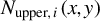 ${N}_{\mathrm{upper},i}\left(x,y\right)$
and
${N}_{\mathrm{upper},i}\left(x,y\right)$
and
 ${N}_{\mathrm{lower},i}\left(x,y\right)$
represent the instantaneous population densities of the manifolds 5I7 and 5I8 in the
${N}_{\mathrm{lower},i}\left(x,y\right)$
represent the instantaneous population densities of the manifolds 5I7 and 5I8 in the
 $i$
th slice, respectively,
$i$
th slice, respectively,
 ${N}_{\mathrm{tot}}$
is the total population density,
${N}_{\mathrm{tot}}$
is the total population density,
 ${\eta}_{\mathrm{p}}$
is the pump quantum efficiency,
${\eta}_{\mathrm{p}}$
is the pump quantum efficiency,
 ${\tau}_{\mathrm{f}}$
is the fluorescence lifetime of the 5I7 manifold and
${\tau}_{\mathrm{f}}$
is the fluorescence lifetime of the 5I7 manifold and
 $k$
is the ETU rate. Note that the stimulated emission term is neglected in Equation (1), which is reasonable because the processes of energy storage (pumping process) and laser amplification (extraction process) are considered separately in this calculation. During the energy storage stage, the rate equations are only used to calculate the energy stored in the crystal during one pump cycle (τ = 1/f). Since no seed laser is injected and no cavity is formed during this process, there is no depletion of the inverted population due to stimulated emission.
$k$
is the ETU rate. Note that the stimulated emission term is neglected in Equation (1), which is reasonable because the processes of energy storage (pumping process) and laser amplification (extraction process) are considered separately in this calculation. During the energy storage stage, the rate equations are only used to calculate the energy stored in the crystal during one pump cycle (τ = 1/f). Since no seed laser is injected and no cavity is formed during this process, there is no depletion of the inverted population due to stimulated emission.
The pump radius and seed beam radius in the
 $i$
th slice are expressed as follows:
$i$
th slice are expressed as follows:
 $$\begin{align}\displaystyle \begin{array}{c}{\omega}_{\mathrm{p},i}={\omega}_{\mathrm{p}0}\sqrt{1+{\left[\frac{M_{\mathrm{p}}^2{\lambda}_{\mathrm{p}}}{n\pi {\omega}_{\mathrm{p}0}^2}\left( i\mathrm{d}z-{z}_0\right)\right]}^2},\end{array}\end{align}$$
 $$\begin{align}\displaystyle \begin{array}{c}{\omega}_{\mathrm{s},i}={\omega}_{\mathrm{s}0}\sqrt{1+{\left[\frac{M_{\mathrm{s}}^2{\lambda}_{\mathrm{s}}}{n\pi {\omega}_{\mathrm{s}0}^2}\left( i\mathrm{d}z-{z}_0\right)\right]}^2},\end{array}\end{align}$$
where
 ${\omega}_{\mathrm{p}0}$
(
${\omega}_{\mathrm{p}0}$
(
 ${\omega}_{\mathrm{s}0}$
) is the radius of the pump (seed) beam waist,
${\omega}_{\mathrm{s}0}$
) is the radius of the pump (seed) beam waist,
 ${M}_{\mathrm{p}}^2$
(
${M}_{\mathrm{p}}^2$
(
 ${M}_{\mathrm{s}}^2$
) is the beam quality factor of the pump (seed) laser,
${M}_{\mathrm{s}}^2$
) is the beam quality factor of the pump (seed) laser,
 ${\lambda}_{\mathrm{p}}$
(
${\lambda}_{\mathrm{p}}$
(
 ${\lambda}_{\mathrm{s}}$
) is the wavelength of the pump laser (seed laser),
${\lambda}_{\mathrm{s}}$
) is the wavelength of the pump laser (seed laser),
 $n$
is the refractive index and
$n$
is the refractive index and
 ${z}_0$
is the location of the beam waist. The incident pump intensity and seed pulse fluence in the
${z}_0$
is the location of the beam waist. The incident pump intensity and seed pulse fluence in the
 $i$
th slice follow a Gaussian distribution:
$i$
th slice follow a Gaussian distribution:
 $$\begin{align}\displaystyle \begin{array}{c}{I}_{\mathrm{p},i}\left(x,y\right)={P}_{\mathrm{in},i}\cdot \frac{2}{\pi {\omega}_{\mathrm{p},i}^2}\exp \left(-2\frac{x^2+{y}^2}{\omega_{\mathrm{p},i}^2}\right),\end{array}\end{align}$$
 $$\begin{align}\displaystyle \begin{array}{c}{J}_{\mathrm{in},i}\left(x,y\right)={E}_{\mathrm{in},i}\cdot \frac{2}{\pi {\omega}_{\mathrm{s},i}^2}\exp \left(-2\frac{x^2+{y}^2}{\omega_{\mathrm{s},i}^2}\right),\end{array}\end{align}$$
where
 ${P}_{\mathrm{in},i}$
and
${P}_{\mathrm{in},i}$
and
 ${E}_{\mathrm{in},i}$
are the incident pump power and seed pulse energy in the
${E}_{\mathrm{in},i}$
are the incident pump power and seed pulse energy in the
 $i$
th slice, respectively. Subsequently, the pump rate in the
$i$
th slice, respectively. Subsequently, the pump rate in the
 $i$
th slice can be written as follows:
$i$
th slice can be written as follows:
 $$\begin{align}\displaystyle \begin{array}{c}{R}_{\mathrm{p},i}\left(x,y\right)=\frac{\sigma_{\mathrm{ap}}{\lambda}_{\mathrm{p}}}{hc}{I}_{\mathrm{p},i}\left(x,y\right),\end{array}\end{align}$$
where
 ${\sigma}_{\mathrm{ap}}$
is the absorption cross-section at the pump wavelength and
${\sigma}_{\mathrm{ap}}$
is the absorption cross-section at the pump wavelength and
 $h$
and
$h$
and
 $c$
are Planck’s constant and speed of light, respectively. The pump absorption coefficient
$c$
are Planck’s constant and speed of light, respectively. The pump absorption coefficient
 ${\alpha}_{\mathrm{p},i}\left(x,y\right)$
and the small-signal gain
${\alpha}_{\mathrm{p},i}\left(x,y\right)$
and the small-signal gain
 ${g}_{0,i}\left(x,y\right)$
in the
${g}_{0,i}\left(x,y\right)$
in the
 $i$
th slice can be written as follows:
$i$
th slice can be written as follows:
 $$\begin{align}\displaystyle \begin{array}{c}{\alpha}_{\mathrm{p},i}\left(x,y\right)={\sigma}_{\mathrm{ap}}{N}_{\mathrm{lower},i}\left(x,y\right)-{\sigma}_{\mathrm{ep}}{N}_{\mathrm{upper},i}\left(x,y\right),\end{array}\end{align}$$
 $$\begin{align}\displaystyle \begin{array}{c}{g}_{0,i}\left(x,y\right)={\sigma}_{\mathrm{es}}{N}_{\mathrm{upper},i}\left(x,y\right)-{\sigma}_{\mathrm{as}}{N}_{\mathrm{lower},i}\left(x,y\right),\end{array}\end{align}$$
where
 ${\sigma}_{\mathrm{es}}$
and
${\sigma}_{\mathrm{es}}$
and
 ${\sigma}_{\mathrm{as}}$
are the emission and absorption cross-sections at the laser wavelength, respectively and
${\sigma}_{\mathrm{as}}$
are the emission and absorption cross-sections at the laser wavelength, respectively and
 ${\sigma}_{\mathrm{ep}}$
is the emission cross-section at the pump wavelength. Owing to the non-negligible laser reabsorption of Ho:YLF, we modified the small-signal gain with
${\sigma}_{\mathrm{ep}}$
is the emission cross-section at the pump wavelength. Owing to the non-negligible laser reabsorption of Ho:YLF, we modified the small-signal gain with
 ${\sigma}_{\mathrm{as}}$
, which better describes the physical process of energy extraction. Subsequently, the incident pump power in the (
${\sigma}_{\mathrm{as}}$
, which better describes the physical process of energy extraction. Subsequently, the incident pump power in the (
 $i$
+1)th slice can be derived as follows:
$i$
+1)th slice can be derived as follows:
 $$\begin{align}\displaystyle \begin{array}{c}{P}_{\mathrm{in},i+1}=\iint {I}_{\mathrm{p},i}\left(x,y\right)\exp \left[-{\alpha}_{\mathrm{p},i}\left(x,y\right) \mathrm{d}z\right]\mathrm{d}x\mathrm{d}y.\end{array}\end{align}$$
The output pulse fluence in the
 $i$
th slice and the incident pulse energy in the (
$i$
th slice and the incident pulse energy in the (
 $i$
+1)th slice can be derived as follows:
$i$
+1)th slice can be derived as follows:
 $$\begin{align}{J}_{\mathrm{out},i}\left(x,y\right)&={J}_{\mathrm{s}}\ln \bigg\{1+\left[\exp \left(\frac{J_{\mathrm{in},i}\left(x,y\right)}{J_{\mathrm{s}}}\right)-1\right]\nonumber\\&\quad \cdot\exp \left[{g}_{0,i}\left(x,y\right)\mathrm{d}z\right]\bigg\},\end{align}$$
 $$\begin{align}\!\!\!\kern1pt{E}_{\mathrm{out},i+1}=\iint {J}_{\mathrm{out},i}\left(x,y\right)\mathrm{d}x\mathrm{d}y,\qquad\ \qquad\end{align}$$
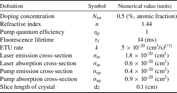
where
 ${J}_{\mathrm{s}}$
is saturation fluence (expressed as
${J}_{\mathrm{s}}$
is saturation fluence (expressed as
 ${J}_{\mathrm{s}}= hc/{\lambda}_{\mathrm{s}}{\sigma}_{\mathrm{es}}$
).
${J}_{\mathrm{s}}= hc/{\lambda}_{\mathrm{s}}{\sigma}_{\mathrm{es}}$
).
Finally, the population density variation between adjacent slices during iterative calculations conformed to the principle of energy conservation:
 $$\begin{align}\displaystyle \begin{array}{c}{N}_{\mathrm{upper},i+1}-{N}_{\mathrm{upper},i}=\frac{\left({J}_{\mathrm{out},i+1}-{J}_{\mathrm{out},i}\right){\lambda}_{\mathrm{s}}}{hc\mathrm{d}z}.\end{array}\end{align}$$
Acknowledgements
This work was supported by the Strategic Priority Research Program of the Chinese Academy of Sciences (Grant No. XDA0380205); the Shanghai Collaborative Innovation Program (Grant No. XTCX-KJ-2024-41); the Shanghai Rising-Star Program (Grant No. 24YF2752900); the China Postdoctoral Science Foundation (Grant No. 2025T180227); the Talent Plan of the Shanghai Branch, Chinese Academy of Sciences; the National Key Research and Development Program of China (Grant No. 2022YFA1604401); and the National Natural Science Foundation of China (Grant Nos. 12388102, 22227901 and U21A20138).


 Open access