


Introduction
The next generation of Internet-of-Things (IoT) devices, and in general wireless sensor networks (WSNs), are composed of many sensors dealing with low power consumption requirements [Reference Correia, Borges Carvalho and Kawasaki1]. In this scenario, where devices need to be kept alive as long as possible to avoid unnecessary battery waste, radiofrequency (RF) energy harvesting (EH) is one of the most promising factors for future WSNs [Reference Kim, Vyas, Bito, Niotaki, Collado, Georgiadis and Tentzeris2–Reference Deng, Yue, Fan, Guan, Xu and Chen4]. Literature has already presented in past years many solutions based on EH systems to correctly supply sensors or devices for applications such as biomedical [Reference Paolini, Feliciani, Masotti and Costanzo5], structural and ambient monitoring [Reference Wardlaw, Karaman and Karsilayan6], and factory management [Reference Moloudian, Hosseinifard, Kumar, Simorangkir, Buckley, Song, Fantoni and O’Flynn7]. In outdoor or dynamic scenarios, devices often need to communicate over varying distances and through different environments, leading to fluctuations in signal strength. In that sense, rectifiers are key components to convert RF power into direct current (DC), and preview the possibility to broaden the power operating range according to the environmental conditions; they are usually composed of diodes and microstrip matching sections [Reference He, Trovarello, Benassi, Masotti, Liu and Costanzo8–Reference Trovarello, Masotti, Aldrigo, Modreanu and Costanzo10], where circuit parameters are designed by using harmonic balance (HB)-based computer-aided design (CAD) methods. Due to microstrips’ narrow-band behavior and the rectifiers’ nonlinear effects, common RF EH systems exhibit optimal performance only for a prescribed power range. Consequently, high values of the RF-to-DC power conversion efficiency (PCE) can be effectively observed when the received power from the harvester is confined within a limited range. For this reason, the adoption of topologies capable of extending the operating region of the rectifier is crucial.
For what concerns far-field wireless power transfer (WPT) systems, power is transferred via radiative electromagnetic (EM) waves between two or more radiating elements, and it can cover long distances typically involving low power levels. Focusing on the transmitting section of these systems, time-modulated arrays (TMAs) are advanced radiating architectures that utilize harmonic contributions from modulating the RF input signal of each antenna element with user-defined pulses. Introduced in paper [Reference Shanks and Bickmore11], TMAs have attracted scientific interest due to their numerous benefits and applications, overcoming traditional phased array limitations, achieving non-uniform excitation, and improving side lobe levels without complex feeding networks [Reference Kummer, Villeneuve, Fong and Terrio12]. They use simple switches to control the amplitude and phase of the input signal, avoiding the need for expensive phase shifters or hybrid couplers. The consequent time-dependent regime is responsible for multi-harmonic radiation, which can be beneficial for harmonic beamforming [Reference Poli, Rocca, Oliveri and Massa13], harmonic beam steering [Reference Tong and Tennant14], direction finding [Reference Chong, Xianling, Zhaojin, Junping and Ronghong15], and WPT itself [Reference Masotti, Costanzo, Del Prete and Rizzoli16].
Also, frequency-diverse arrays (FDAs) are cutting-edge antenna systems in which a frequency diversity scheme is introduced among the signals radiated by the array elements [Reference Antonik, Wicks, Griffiths and Baker17]. This mechanism creates a dynamic radiation pattern, with intrinsic scanning capabilities [Reference Secmen, Demir, Hizal and Eker18]. FDAs are particularly useful for applications like localization [Reference Çetiner, Demir and Hizal19] and WPT [Reference Wang20], as they can achieve high accuracy and control in radiation without requiring complex and expensive components like phase shifters.
Nevertheless, another critical aspect to consider is the fabrication process of RF antennas and circuitries: in that sense, the advent of three-dimensional (3D) printing, also known as additive manufacturing (AM), has significantly impacted many engineering research fields, enabling more flexible, efficient, wasteless, and cost-effective manufacturing processes. By simply creating 3D physical models using 3D CAD software, AM simplifies the production of complex geometries and engineered structures that are otherwise difficult to achieve with traditional manufacturing methods, still with high precision and affordable materials.
These aspects have become very attractive for many applications such as aerospace and automotive engineering, where 3D printing provides high-precision, fast, massive-scale production of miniaturized components whose structural weight is reduced without compromising the required structural properties [Reference Mishra and Jagadesh21]. This also reduces fuel consumption and carbon emissions, as compared with the conventional injection molding process, also dropping the production costs. Moreover, the benefits of AM have significantly boosted the research in medicine and biomedical device applications. As a result of the population aging, the increasing prevalence of chronic diseases, and the technological advances, the global financial outlay of the healthcare industry toward biomedical device design and development is growing at a remarkable rate, catalyzing significant progress with regard to biomedical materials for tissue engineering, drug delivery, surgical and diagnostic tools, implants and prosthetics, optoelectronics, sensing components, wireless communication hardware, and battery technology [Reference Appuhamillage, Ambagaspitiya, Dassanayake and Wijenayak22, Reference Won, Cai, Gutruf and Rogers23].
Enhanced power range technologies for RF EH
The development of circuit topologies able to increase the dynamic range of rectifiers for RF EH applications has stimulated high interest given the high application variety of rectifiers. Microwave rectifiers, which are composed of Schottky diodes or transistors, offer nonlinear complex input impedances, which are strictly dependent on the input power levels. Schottky diodes provide a low resistive and capacitive reactive input impedance [Reference Masotti, Costanzo, Francia, Filippi and Romani24]. As the input power increases, the nonlinear effects increase too, resulting in a change of the reactive part of the input impedance (Zin), and in general of the complex Zin. Figure 1 shows the reactive part of the Zin of three different commercial Schottky diodes (SMS7630, SMS7621, and SMS3922, manufactured by Skyworks), frequently adopted in the design of microwave EH systems. As the input power increases, the capacitive reactance tends to decrease, showing the strong nonlinear relation between Zin and voltage across the diode junction.
Nonlinear imaginary part of the input impedance for three different commercial Schottky diodes.

Typically, an RF-EH system is composed of a receiving antenna and a nonlinear device, where the conjugate matching between the antenna and the rectifier is actuated by means of lumped or distributed elements, such as microstrips, as shown in Fig. 2.
Block schematic of an RF-EH system.

In general, the linear subnetwork must be optimized together with the rectifying circuit and the rectenna load to efficiently convert the RF power incident on the receiving antenna into DC power (PDC) delivered to the load. The PCE represents one of the key figures of merit of rectifiers for EH applications and it is calculated by the following equation:
 \begin{equation}{\eta _{RF - DC}} = {\text{ }}\frac{{{P_{DC}}}}{{{P_{RF}}}}\end{equation}
where PRF is the RF power at the rectifier input port.
Single matching sections even though are a good solution for limited power-range solutions, present critical performance when a wide power range is desired. To extend the operating range of EH rectifiers, the key idea is to combine multiple rectifiers, and consequently multiple matching sections, each one optimized to operate and maximize the PCE in a specific input power range. Many solutions have been presented in the literature proposing different approaches to increase the operating range of RF harvester. Two main categories can be distinguished: passive adaptive networks and active adaptive networks. The first category relies on the design of multiple matching sections, which are specifically designed to offer the correct conjugate matching depending on the input power level. The active matching networks, on the contrary, exploit nonlinear devices, such as single-pole double-through (SPDT) and field-effect transistors (FET), to correctly distribute the input power in the most accurate branch.
Passive adaptive networks
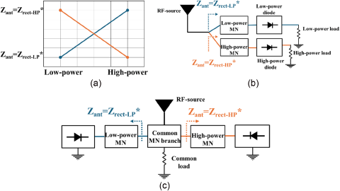
The enhancement of the dynamic range is often achieved by the implementation of passive adaptive networks and multiple rectifier branches. The key idea is to design two or more harvesters, carefully designed in specific operating input power ranges, by tuning the matching branches to present power-dependent conjugate matching. Usually, a low-power and a medium-high-power branch are adopted. By adjusting the matching branch parameters, such as the width and length of the microstrip lines, it is possible to correctly present a conjugate matching of the branch, for a specific power range. In this way, when low input power levels are present at the input port of the RF EH system, only the low-power branch is correctly matched with the RF source, while the high-power branch, offering a high-mismatch impedance, is deactivated. Similar considerations can be derived for high-power levels present at the input port of the multi-branch rectifier. Figure 3(a) shows the operating principle of the common passive adaptive distribution network technique for enhanced power range rectifiers. Adaptive distribution-based rectifiers which employ the usage of carefully designed input impedance compensation networks can be divided into two main categories: multiple load rectifiers and common load rectifiers. Figures 3(b) and 3(c) show the typical topology based on passive distribution networks for multiple loads and common load rectifiers, respectively. Usually, multiple load-based solutions offer higher PCEs compared to the shared load rectifiers. Indeed, rectifiers operating in different input power level regions rely on different matching sections to maximize the power transfer at the output. To do that, the output resistive load plays an important role, being part of the optimization variables set of the harvester [Reference Masotti, Costanzo, Francia, Filippi and Romani24]. On the other hand, common load solutions, adopt a simpler topology, where less components are needed, resulting in decreasing sizes of the designs.
(a) Desired input impedance for different power ranges; (b) multiple and (c) common load topologies for wide dynamic range rectifiers based on passive network distribution technique.
In paper [Reference Zheng, Wang, Leung and Chan25], a wide-range rectifier operating at 2.4 GHz, adopting a multiple load solution is reported. The RF signal is automatically routed to the most suitable branch employing a compensation microstrip network. To maintain an efficient rectification, for low input power levels, only one of the diodes rectifies the RF signal, while for the high input power region, both diodes rectify the RF signal cooperatively. In this way, a PCE higher than 50% is maintained from −6 to 26.5 dBm of the input power level. Similar topologies based on passive compensation networks are presented in papers [Reference Wang, Yang, Yang, Huang, Che and Monti26–Reference Kim and Oh28]. In paper [Reference Wang, Yang, Yang, Huang, Che and Monti26], a wide-range rectifier operating at 2.4 GHz with a PCE higher than 50% from −1.5 to 24.4 dBm is reported, where the overall dynamic operating range is 40 dB.
Wide dynamic range rectifiers adopting common loads are presented in papers [Reference Xiao, Ou, Du, Zhang, Che and Xue29–Reference Argote-Aguilar, Wei, Hutu, Villemaud, Gautier, Berder and Negra33]. In paper [Reference Xiao, Ou, Du, Zhang, Che and Xue29], an integrated impedance compression network is adopted to improve the matching between the RF source and two diodes in parallel connection with no impedance limitation. This solution, operating at 2.45 GHz, exhibits a PCE higher than 70% for an 18-dB power range. In paper [Reference Bo, Ou, Wang, Tang and Zhang30], a common load approach is adopted to design and fabricate a polarization-independent rectifier working in the 1–2.7 GHz and for an input power range of 18.5 dB. Through a six-port coupling network and four parallel-connected rectifiers, the system can maintain a stable PCE over different polarizations of the incident field. Anyway, the solution is not suitable for low-power applications due to the near-zero PCE below −10 dBm present at the input port of the rectifier. An X-band rectifier using capacitive compensation to extend the input power range is reported in paper [Reference Lin, Chen, He, Xiao, Che and Liu32]. Two diodes are adopted to cancel the imaginary parts of each other’s impedance. Moreover, the two nonlinear devices share the same DC output voltage. With the proposed architecture, the rectifier, operating at 9.7 GHz, exhibits a PCE higher than 50% for approximately 15 dB of input power range. Given the higher operating frequency and the common load topology, the dimensions of the fabricated prototype are below 500 mm2. Anyway, as most of the previously reported literature works, the rectifier cannot operate efficiently in low-power applications since the lowest reported input level is 5 dBm.
Active adaptive networks
Wide dynamic range rectifiers based on active adaptive networks exploit nonlinear devices, such as FETs or RF switches, to direct the RF power flow in the correct branch. As for the passive compensation networks, for active network-based solutions multiple rectifiers, working in different power ranges, are designed. The two main topologies present in the literature to achieve the correct distribution of the input power flow are depicted in Fig. 4. In Fig. 4(a), the topology presented in paper [Reference Yoshida, Fukuda, Noji, Tashiro, Kobayashi and Kawasaki34] is reported, where the wide dynamic range capabilities are achieved using SPDT switches controlled by a low-power central processing unit (CPU). The input RF signal is injected into a directional coupler, which conveys a portion of the RF flow to a power monitoring unit, which controls the SPDT switches and selects the appropriate rectifier automatically. Using a three-stage rectifier, the system can operate from 5 to 45 dBm of input power. As a result, the system has over 30 dB range of input power with an efficiency greater than 25%. Despite the solution presented in paper [Reference Yoshida, Fukuda, Noji, Tashiro, Kobayashi and Kawasaki34] was the first attempt to exploit active devices to enhance the dynamic range of rectifiers, the adoption of multiple circuits, such as CPU and power monitors, indeed produces a decrease in the total PCE of the harvesting device.
(a) Topology of the wide dynamic range rectifier based on an active distribution technique with external input and (b) without external input.
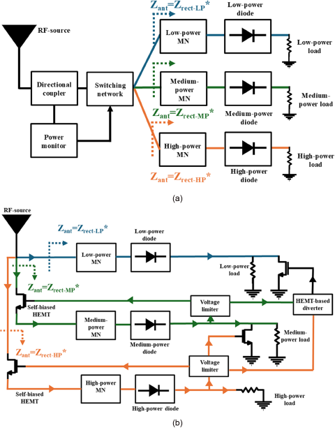
In Fig. 4(b), the circuit scheme of the solution presented in paper [Reference Trovarello, Paolini, Masotti and Costanzo35] is reported. Starting from the idea presented in papers [Reference Trovarello, Paolini, Masotti and Costanzo36, Reference Del Prete, Masotti and Costanzo37], a three-stage rectifier with a wide dynamic operating range is presented. The system is composed of a parallel connection of three rectifier branches, each optimized for a specific power range; these rectifiers are automatically and sequentially activated based solely on the incoming RF power, without necessitating any external control mechanisms. This unique feature is achieved by directly connecting the three rectifiers to a floating-gate unbiased high-electron-mobility transistor (HEMT). Additionally, ad hoc designed switching networks are incorporated into the rectifiers’ DC paths to facilitate the activation and deactivation of the branches by adjusting the rectifiers’ DC loads.
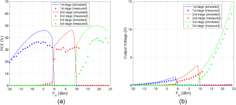
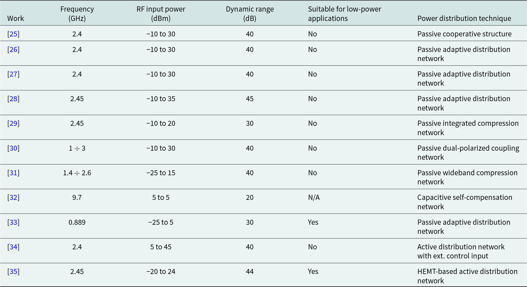
Three rectifiers are designed for different operating ranges: a low-power branch from −20 to 0 dBm, a medium-power branch from 0 to 10 dBm, and a high-power branch from 10 to 24 dBm. When the power level present at the input port is lower than 0 dBm, all the RF power is directed in the low-power branches, which are deactivated using the high impedance of HEMTs in the RF paths. When the system operates in a large-signal regime, the self-polarization phenomenon can be exploited to create DC contributions from the even order responses and to automatically turn on the two self-biased HEMTs. To prevent the breakdown of diodes working in the wrong operating ranges, decoupling networks based on HEMTs in DC configurations are adopted. In this way, only one rectifier is active for each input power level, enhancing the dynamic range of the circuit. Due to low-power applications on which RF energy harvesters are required to work, the system is specifically designed to provide a sufficient PCE for very low input power. Compared to other topologies reported in the literature, for both passive and active distribution techniques, the work reported in paper [Reference Yoshida, Fukuda, Noji, Tashiro, Kobayashi and Kawasaki34] demonstrates the feasibility of a modular topology, enabling the straightforward addition of branches to accommodate a higher dynamic range, if necessary. The performance of the wide dynamic range three-stage rectifier of paper [Reference Trovarello, Paolini, Masotti and Costanzo35] is reported in Fig. 5, where the measured PCE and open-load DC output voltage are reported. From both simulations and measurements, the wide operating range can be noticed. An overview of the wide dynamic range rectifier solutions adopting both passive and active power distribution networks is reported in Table 1.
(a) Measured and simulated PCE of the three-stage wide dynamic range rectifier presented in paper [Reference Trovarello, Paolini, Masotti and Costanzo35], and (b) corresponding open-load DC output voltage. © 2023 IEEE.
Comparison of wide dynamic range EH solutions
Real-time and on-demand beam-steering power transmission via time and frequency diversity schemes
Different solutions have been proposed in the literature for the increase of the overall link efficiency in WPT applications, such as the exploitation on the transmitting side of a retrodirective array for target tracking of the receiving rectenna [Reference Dale Ambatali, Nakasuka, Yang and Shinohara38], or the usage of Rotman lenses on the receiving side for wide angular coverage still maintaining a high gain [Reference Lynch, Adeyeye, Eid, Hester and Tentzeris39]. To the authors’ opinion, these solutions represent steps forward, but still lack real-time reconfigurability that will be a compulsory feature for future WPT scenarios.
In the following, two classes of extremely promising transmitting architectures owing to the envisaged dynamic radiation mechanism are described.
Time-modulated arrays
Most work on TMAs has focused on optimization schemes and algorithms that use duty-cycle and delay of the control switches as design variables, such as binary optimized time sequences [Reference Yang, Gan, Qing and Tan40], pulse shifting [Reference Poli, Rocca, Manica and Massa41], and subsectional optimized time steps [Reference Zhu, Yang, Zheng and Nie42]. In paper [Reference Yang, Wang and Guo43], by preprocessing the rectangular pulses with the sinusoid-based control signal, harmonic beams are independently steerable. However, there is a notable limitation in the literature; despite the effectiveness of these synthesis methods, little effort has been made toward the practical implementation of the control network. This becomes a significant issue with a large number of radiating elements, crucial for high-directivity applications like selective WPT operations. While the problem is manageable for a linear TMA, there are no practical guidelines or implementations for time-controlling a 2D array. This gap can be filled by a simple multi-spoke planar TMA that exploits circular symmetry that allows a high number of antennas (24 patches operating at 2.45 GHz) to be easily controlled by only a few switches (8, for the present case) [Reference Fazzini, Tiberi, Costanzo and Masotti44].
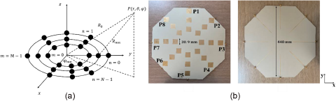
Let us consider an array of ideal isotropic elements that lay on M different rings arranged in N different spokes, as shown in Fig. 6(a). Defined with mnth the element associated to the mth ring in the nth spoke, and ideally considering a switch for each antenna element, the total transmitted signal in the far field of the TMA can be expressed as follows:
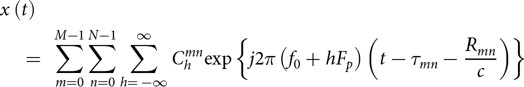 \begin{align}&x\left( t \right) \nonumber \\ & \quad= {\text{ }}\mathop \sum \limits_{m = 0}^{M - 1} \mathop \sum \limits_{n = 0}^{N - 1} \mathop \sum \limits_{h = {\text{ }} - \infty }^\infty C_h^{mn}{\text{exp}}\left\{ {j2\pi \left( {{f_0} + h{F_p}} \right)\left( {t - {\tau _{mn}} - \frac{{{R_{mn}}}}{c}} \right)} \right\}\end{align}
(a) Scheme of the radial topology with N spokes and M rings; (b) top and bottom view of the multilayer prototype of the radial TMA operating at 2.45 GHz [Reference Fazzini, Tiberi, Costanzo and Masotti44]. © 2024 IEEE.
where Rm is the distance between the mnth element and the generic far-field point P(r,θ,ϕ), Chmn is the complex Fourier coefficient, Fp is the modulation frequency and τmn is the delay of the modulating periodic pulse. Equation (2) highlights the very well know TMA radiation mechanism for which for h = 0 a broadside radiation is ensured, while for h ≠ 0 the beam steering is ensured as a function of the delay values.
Due to the complexity of handling M × N switches, especially for highly directive WPT radiators, a solution can be individuated by arranging the radiating elements into N groups of M elements, each group aligned along a spoke to form a series-fed antenna array. This allows each spoke to be controlled by a single RF switch, exploiting therefore a highly symmetric layout, and significantly reducing the complexity of the control network. To this aim, a radial layout with 24 elements (N = 8 spokes with M = 3 elements each) resonating at 2.45 GHz realized on a multilayer stack-up of Rogers RO4350B of 1.524 mm thickness and RO4360G2 of 0.610 mm thickness has been designed, realized, and is shown in Fig. 6(b).
A simple example of optimization is provided to demonstrate the ease of real-time reconfigurability in terms of high directivity bidimensional beam steering of the desired harmonics despite the reduced set of optimization variables, with the goal of having the maximum of the first harmonic (h = ± 1) only 4 dB less than the fundamental one, to steer it in θt = 20° for ϕ = 0° and to reduce the amplitude of the higher harmonics (h ≠ ± 2) of at least 10 dB in terms of power with respect to the first one.
The excitation sequences depicted in Fig. 7(a) achieve the optimization goals, as evidenced by Fig. 7(b) and 7(c). The first harmonic points in the desired direction with a directivity of 12.4 dB, which is only 4 dB lower than the fundamental frequency. Figure 7(c) illustrates the maximum directivity (in dB) for the first three symmetric harmonics, each oriented in different directions. Notably, for the second harmonic, there is a reduction of approximately 12 dB compared to the first harmonic and 16 dB compared to the fundamental frequency. Additionally, due to the circular symmetry, any sequence for a pointing direction (θt, ϕt) can be rotated to a point in the same θt, but on a different plane p∙45° + ϕt, just circularly shifting of p positions the ports, reducing significantly the number of optimized control sequences needed by a factor of 8.
(a) Optimized control sequence; (b) directivity in the ϕ = 0 plane for the fundamental and the first harmonic; (c) maximum directivity at different harmonics [Reference Fazzini, Tiberi, Costanzo and Masotti44]. © 2024 IEEE.

Frequency diverse arrays
In recent decades, FDAs have attracted scientific interest for their unique radiation properties. Each element in an FDA system radiates at a slightly different frequency based on a predefined distribution rule [Reference Huang, Tong and Baker45]. This creates a radiation pattern with joint time-angle-range dependency, as shown by equation (3) for a linear FDA with M elements, as in Fig. 8(a).
 \begin{align} AF\left( {t,\vartheta ,r} \right) &= \mathop \sum \limits_{m = 0}^{M - 1} \exp \left( {j2\pi {f_0}\left( {\frac{{m \cdot l\sin \left( \vartheta \right)}}{c}} \right)} \right) \nonumber \\ & \quad\cdot \exp \left( {j2\pi \Delta {f_m}\left( {t - \frac{{{r_0}}}{c}} \right)} \right)\end{align}
(a) Linear FDA layout and normalized transmitted FDA beam pattern: (b) standard FDA and superimposed pulse (dashed line), (c) pulsed FDA [Reference Tiberi, Fazzini, Costanzo and Masotti51]. © 2023 IEEE.
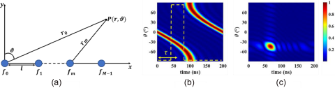
where fm denotes the operating frequency of the mth element, f0 is the carrier frequency, and Δf is the constant frequency offset between consecutive antennas of the array.
This kind of pattern is affected by a time-angle coupling that implies an automatic steering of the main beam over time. This feature is a strong limitation whenever a precise and angle-confined transmission is required, such as for far-field powering purposes. For this reason, research has focused on improving FDA radiation accuracy and control for applications like WPT [Reference Yao, Rocca, Wu and Massa46]. In paper [Reference Khan, Qureshi and Saeed47] a logarithmic increasing frequency offset has been introduced among the array elements to replace the traditional S-shape pattern of linear FDAs with an almost dot-shape pattern. Interestingly, this method allows to cancel the space and time periodicity typical of traditional FDAs thanks to the logarithmic distribution of the frequencies. Then, other works focused on the implementation of the FDA principle to advanced array layouts. For example, in paper [Reference Jones and Rigling48] a planar rectangular array and in paper [Reference Akkoç, Afacan and Yazgan49] a planar array with circular symmetry have been proposed. These array geometries show great potentialities in terms of radiation accuracy and control, enabling the generation of a dot-shape beam pattern. However, from a practical point of view, all these alternatives introduce a high level of complexity either for the signal’s generation or for the array architecture, which is unaffordable.
Recently, a new system called pulsed FDA has been proposed as an effective solution to these problems, relying on a pulse modulation of the sinusoidal signals at each antenna port. This radiation control transfers the complexity to the piloting part of the system, which can be easily handled using a software-defined radio, as demonstrated for the first time in paper [Reference Fazzini, Costanzo and Masotti50]. Furthermore, a crucial step forward has been conducted in paper [Reference Tiberi, Fazzini, Costanzo and Masotti51], in which a novel harmonic analysis of the pulsed FDA has been carried out. Let us consider the same linear array of Fig. 8(a), with linear frequency distribution fm = f 0 + mΔf.
Modulating each transmitted signal with a periodic pulsed waveform of frequency Fp, it is possible to define the total transmitted signal as follows:
 \begin{equation}x\left( t \right) = \mathop \sum \limits_{m = 0}^{M - 1} \mathop \sum \limits_{h = - \infty }^\infty {C_h}{\text{exp}}\left( {j2\pi \left( {{f_m} + h{F_p}} \right)t} \right){\text{exp}}\left( {j2\pi h{F_p}\tau } \right)\end{equation}
where Ch represents the complex Fourier coefficient of order h of the modulating pulse. If this strategy is applied, the S-shape pattern of the standard FDA is replaced in favor of a confined spot in the direction correlated to the ON-time of the pulse. The size and direction of the radiated spot in an FDA can be easily adjusted by varying the pulse duty cycle d and delay τ. By selecting specific pulse parameters, a pulsed FDA can restrict the standard S-shape pattern (Fig. 8(b)) to a confined angular sector, creating a dot-shape radiation (Fig. 8(c)). Varying the pulse delay enables on-demand beam steering. This system behaves like a phased array without the need of expensive phase shifters, but using simple switches at each antenna port, making the design simple and affordable. In Table 2 a comparison between pulsed FDA, TMAs, and other solutions proposed in the literature is shown.
Comparison between different architectures
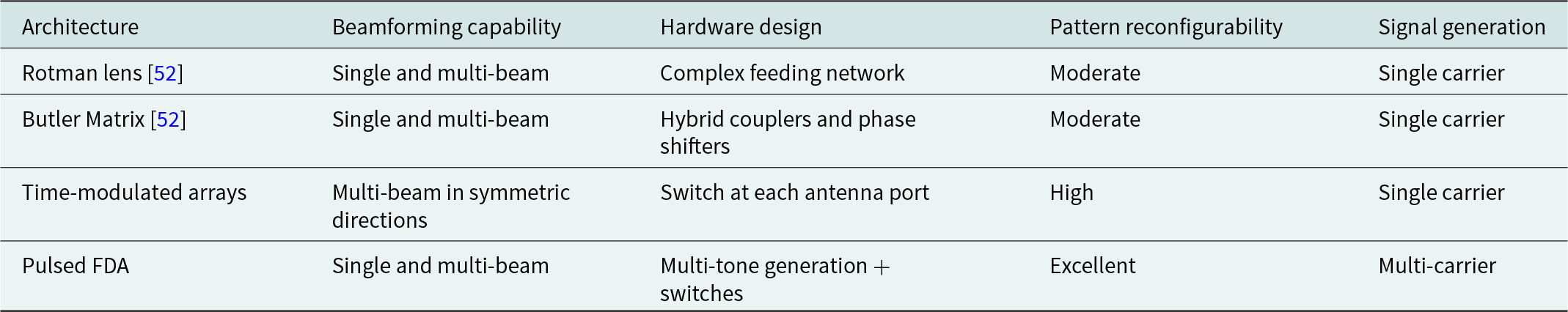
Despite architectures based on Rotman lens or on Butler Matrix have advanced beamforming capabilities, they require very complex and expensive feeding networks adopting distributed hybrid couplers and phase shifters. On the other hand, the great advantage of TMAs and pulsed FDA stands in their high level of reconfigurability obtained with a reduced design complexity.
However, the pulse modulation strategy, adopted in pulsed FDA, generates infinite harmonic products due to the intermodulation of the carrier signals with the pulse frequency Fp. The impact of those harmonics on the radiating performance of the array can be described through a figure of merit named “power loss” (Ploss), computed as the percentage of the harmonics that falls outside of the interested bandwidth respect to the total harmonics generated by the system.
This parameter requires a careful analysis to preserve the effectiveness of the pulsed FDA for WPT applications. If power transmission is the only concern, the harmonics generation can be positively exploited by maximizing the distribution of those superior tones inside the operating bandwidth of the system. It must be underlined that, for powering purposes, in-band interference is not an issue and the higher the number of harmonics involved the better the efficiency of the transmitter. In this context, a linear array of M = 4 monopole antennas are considered with f 0 = 1.8 GHz, Δf = 5 MHz. A valid use case for WPT is found setting F p = Δf, so that the FDA periodicity (1/Δf) is equal to the pulse periodicity, and a unique radiation direction within the FDA period is guaranteed. The pulse duty cycle is set to 0.1, to generate a selective and precise spot of radiation, and its delay is τ = 0 ns to ensure broadside radiation. Given this reference case, the pulsed FDA performance for different control pulses has been derived numerically and then validated through a measurement campaign, whose results are presented in Table 3, considering an available bandwidth Bw = 100 MHz.
Ploss levels (duty cycle: 0.1, Bw = 100 MHz)
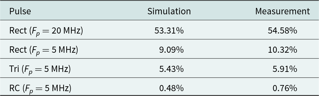
As can be evinced from the results the choice F p = Δf is a valuable solution to minimize the amount of power lost out of the bandwidth. Indeed, the intrinsic pulse harmonics are positively exploited for powering purposes, preserving the effectiveness of pulsed FDA for WPT applications. In particular, the pulsed FDA based on a raised cosine pulse (RC) with roll-off factor equal to 1, guarantees the lower levels of Ploss in the entire frequency range. Instead, from the radiation accuracy perspective, the triangular pulse (Tri) control can generate the most accurate beam spot thanks to its waveform selectivity. Overall, the pulsed FDA system based on triangular pulse modulation is considered the most promising choice for WPT, because it fulfills the trade-off between highly selective radiation and minimized Ploss.
3D-printable antennas and RF circuitries for battery-free applications
The development of antennas and RF circuitries for battery-free biomedical devices can be considered one of the most emerging applications, within the framework of far-field radiative WPT. These innovative systems harness the principle of harvesting energy from surrounding environmental sources allowing them to operate without the need for conventional batteries, hence avoiding their maintenance and/or surgical interventions for their replacement [Reference Lou, Li, Wang and Shen53]. This capability makes these systems ideal for implantable and/or wearable medical applications, where the primary requirements include being lightweight, miniaturized, and noninvasive. As a result, devices such as wearable straps, pads, wristbands, or skin conformal tattoos [Reference Ray, Choi, Bandodkar, Krishnan, Gutruf, Tian, Ghaffari and Rogers54] offer greater comfort to patients, being less intrusive, and enable continuous, long-term monitoring or therapeutic functions without the need for surgical replacements or external power management, facilitating early diagnosis and treatment of diseases and leading to improved patient outcomes and long-term reductions in healthcare costs [Reference Mamo, Adamiak and Kunwar55].
Conventional materials commonly implemented for these kinds of planar electronic devices are inorganic, and their high elasticity Young modulus, brittle mechanical properties are inherently ill-suited for bio-integration. Therefore, with the advent of AM and nanotechnology [Reference Cho, Sunwoo, Hong, Koo, Kim, Baik, Hyeon and Kim56], a great effort has been dedicated towards the development of soft materials with mechanical characteristics close to those of tissues such as flexibility, stretchability, ultra-thinness, and lightweight to ensure mechanical deformability of the wearable/implantable bioelectronics and its conformal contact onto soft curved surfaces and tissues such as brain, heart, and skin, in order to measure high-quality bio-signals, deliver real-time feedback treatments, and provide long-term biocompatibility in vivo. Any sufficiently thin material is flexible since bending strains decrease linearly with thickness: a silicon wafer is brittle and rigid, but nanoscale ribbons, wires, or membranes of silicon are flexible [Reference Kim, Lu, Huang and Rogers57]. Thus, electronic metals and semiconductor materials can be patterned in micro-structured and nanostructured forms such as carbon nanomaterials, buckled nanoribbons, serpentine nanowires and wavy, mesh structures, intimately integrated with elastomeric substrates and encapsulants, such as polydimethylsiloxane, polyimide, or parylene, yielding systems to flex, stretch and compress with a uniform distribution of deformation-induced stress and minimized strain. Many different printing methods are used for patterning nanocomposites including inkjet printing and extrusion 3D printing, soft lithography methods (mold casting, transfer printing, stencil printing), and light-based lithography methods (photolithography, stereolithography, and laser cutting) [Reference Cho, Sunwoo, Hong, Koo, Kim, Baik, Hyeon and Kim56].
Moreover, when dealing with flexible system-on-package designs it is crucial to ensure reliable wideband performance, minimum parasitic losses, compact modules, and robust mechanical flexibility for seamless conformity to various conformal platforms [Reference Hu, Zhou, Sitaraman and Tentzeris58]. In this sense, conventional interconnections between ICs and the packaging substrate or printed circuit board (PCB) are typically realized with thermosonic ribbon or wire bonds, that could introduce parasitic inductances at high frequencies or accidentally cause radiation losses due to their arching nature. Therefore, inkjet printing and 3D-printed interconnects offer a more robust, planar, and adaptable structures, resulting in enhanced RF performance and providing on-demand packaging with various materials and the rapid creation and assembly of diverse, customized components in a conformal layout that integrates printed interconnections, printed insulating layers, and printed conductive traces. In paper [Reference Hu, Zhou, Sitaraman and Tentzeris58], ramp interconnects are partly inkjet printed with SU8 dielectric ink for the ramp base and partly with silver nanoparticle ink for the conductive interconnects to build the connection between the die and microstrip lines. These ramps are engineered to deliver outstanding and dependable performance for flexible packaging within the 20–40 GHz frequency range achieving a superior S21 performance with an insertion loss below 1.16 dB per interconnect throughout the whole operation range, even under tested bending conditions of curved mounting platforms.
Furthermore, to address the need for flexible and deformable communication systems, particularly in applications such as wearable electronics, soft robotics, and biomedical devices, antennas must be designed to maintain performance under mechanical strain, offering adaptability in dynamic environments.
Stretchable antennas based on these patterned conductive films on elastomeric substrates have been previously designed in literature using open-mesh, serpentine structure layouts [Reference Kim, Basir, Herbert, Kim, Yoo and Yeo59−Reference Park, Shin, McCall, Al-Hasani, Norris, Xia, Brenner, Noh, Bang, Bhatti, Jang, Kang, Mickle, Dussor, Price, Gereau, Bruchas and Rogers62].
As an example, in paper [Reference Kim, Basir, Herbert, Kim, Yoo and Yeo59] an extensive analysis of the material behaviours regarding stretchable mechanics in relation to three crucial factors (substrate thickness, copper pattern width, and copper thickness) in antenna designs has been assessed; a figure of merit named average effective modulus has been introduced taking into account the averaged slope of the stress-strain curves in the initial strain region and evaluated for different configurations to consider their effective wearability.
In paper [Reference Nappi, Su, Luan, Rogers and Marrocco60], a stretchable sensor skin for soft object surface wireless monitoring has been designed exploiting a space-filling curve pattern at a large-scale, with a meandered contour in microscale; this showed the ability to maintain its shape under stretch up to 35% due to this double-scale meanderings.
Strategies for converting rigid planar microwave systems to stretchable systems using serpentine mesh layouts have been investigated in order to find the best trade-off between mechanical stretchability and microwave power dissipation, that may be caused by impedance changes along the mesh layout directly related to changes in the curvature and morphology of the serpentine traces [Reference Chang, Tanabe, Wojcik, Barksdale, Doshay, Dong, Liu, Zhang, Chen, Su and Lee63].
Besides, 3D printing also presents numerous advantages in the selection and custom design of the supporting flexible bioplastic materials used as substrates of battery-free wearables, providing an easy and rapid prototyping and fabrication with cost-effectiveness, and the possibility to produce intricate geometries and heterogeneous soft functional materials tailored to specific biomedical requirements. With this regard, low-cost biocompatible and biodegradable 3D printable polymers such as thermoplastics (nylon, acrylonitrile butadiene styrene [ABS], polylactic acid [PLA], polyethylene terephthalate, polyetherimide, etc.), are not conventionally used in the fabrication of flexible wearable health-monitoring devices because of their bulky interfaces, rigid nature, low bending stiffness, and, more importantly, their poor EM dielectric characteristic (dielectric relative permittivity εr and loss tangent tan(δ)) which make them not suitable to be implemented as substrates for antennas and RF circuitries, compared to specialized stiff RF materials. When dealing with 3D-printed dielectrics, it is crucial to first measure the dielectric properties of several test samples, since different printer settings, as nozzle width and temperature, extrusion speed, sample thickness and material infill percentage, can impact the frequency response and loss tangent. For this reason, different EM dielectric characterization techniques allow to derive the specific sample’s EM characteristics in a frequency range that varies depending on the application. One of the simplest methods providing wideband dielectric characterization is the microstrip T‐resonator method [Reference Costanzo, Donzelli, Masotti and Rizzoli64] that consists in the fabrication of a microstrip line connected to an open stub, of a length that determines its periodic resonating frequencies, whose scattering parameters (S-matrix) are first measured; then the same structure is reproduced on a CAD software and full-wave iteratively simulated for varying relative dielectric constant and conductivity values, with the goal of broadband matching the S-parameter measurements.
For instance, this technique has been previously used for the EM dielectric characterization of the most common materials used in fused filament fabrication, ABS and PLA, revealing an εr ∼ 2.45 and a tan(δ) ∼ 0.005 in the frequency range 2–60 GHz of the former, and an εr ∼ 2.65 and tan(δ) ∼ 0.03 in the frequency range up to 10 GHz of the latter [Reference Boussatour, Cresson, Genestie, Joly and Lasri65−Reference Whittaker, Zhang, Powell, Stevens, Vardaxoglou and Whittow67]. However, in recent years, numerous researchers have demonstrated the EM advantages of 3D engineered materials and structures for the fabrication of antennas, in the place of traditional costly and time-consuming subtractive manufacturing methods, such as etching and machining, leading to the production of more cost-effective, efficient, and lightweight 3D printable devices for low-cost and energy-autonomous health-monitoring wearables. In this sense, the almost unlimited degrees of freedom offered by AM material synthesis allow for the creation of intricate internal structures tailored for specific dielectric properties, namely, the variation of εr across two or even three axes, and the reduction of tan(δ) responsible for the intrinsic losses, affecting EM propagation and radiation. The material engineering is achieved by regulating the material infill percentage and the empty/full pattern ratio simultaneously accounting for the resulting EM and mechanical properties aiming at making these materials suitable for high-performance RF circuits and antennas design. This concept has been widely employed even for the design of ultrawideband microwave flat gradient index lenses, as described in paper [Reference Zhang, Arya, Whittow, Cadman, Mittra and Vardaxoglou68], where the empty/full ratio of 3D-printed ABS is gradually and radially varied to modify locally the refractive index profile to manipulate the ray paths providing broadband gain improvement of open-ended waveguide sources. In the same way, drawing inspiration from contemporary manufacturing practices in the aerospace, shipbuilding, and automotive industries, sandwich structures represent an optimal choice for the antenna substrate design, providing both good EM properties, structural lightweight, and mechanical robustness [Reference Ijaz, Saleem, Zain-ul-abdein, Mabrouki, Rubaiee and Bin Mahfouz69]. This structure features an engineered core typically designed as honeycomb, truss, and foam patterns to absorb bending movements and transverse shear forces, flanked at the top and bottom by thin sheets of material. These various core shapes have been derived from a thorough study of living organisms such as honeycombs, glass sponges, beetle forewings, and bamboo, which exhibit exceptional low weight and damage resistance [Reference Zhang, Yang, Li, Huang, Feng, Shen, Han, Zhang, Jin, Xu and Lu70, Reference Li, Guo, Chen and Chen71].
The mixture of air and 3D-printed material resulting from this structural engineering can be characterized as an artificial dielectric with effective properties defined by the properties of the two constituent materials and their fractional volumes: this mixture can be considered and discretized as homogeneous inclusions embedded in another homogeneous medium. Thus, an effective permittivity (εeff) can be derived if it is assumed that the mixture responds to EM excitation as if it were homogeneous. This homogenization theory of heterogeneous media is valid until the size of the inclusions in the mixture and the spatial correlation length of the permittivity function are small with respect to the wavelength (∼λ/10) [Reference Sihvola72].
As an example for this technique, it is worth noticing that in paper [Reference Battistini, Paolini, Costanzo and Masotti66] the top and bottom sheets of the engineered structure are made of two 300 µm-thick layers of PLA enclosing a 1.4 mm-thick central core that is designed with the shape of a honeycomb with octagonal air-filled cells. The ideal balance between high EM radiation performance and mechanical durability has been achieved by optimizing the octagonal shape, size, and inter-octagonal spacing (details in Fig. 9).
Stack-up of the structure realized on a 3D-printed PLA substrate made up of a honeycomb core with octagonal cells [Reference Battistini, Paolini, Costanzo and Masotti66]. © 2023 IEEE.
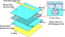
The optimal design for the working frequency of 2.45 GHz is 4-mm-radius octagonal cells, which meets two objectives: minimizing the amount of PLA and hence the intrinsic propagation losses and preserving a rigid PLA structure. The octagonal air cavities in this optimized pattern have a proportion of 52% of air and 48% of PLA and are joined by plastic inclusions. Effective EM parameters that take into consideration the field propagating in both materials and the related boundary conditions resulting from the material pattern are required to depict this mixture of air and plastic material.
This work also proposes an innovative two-port antenna structure engineered with the abovementioned 3D structure, to codesign a novel advanced microwave wearable system (i.e., an energy-autonomous wearable tag) that can generate a quasi-ultrawideband (q-UWB) signal for indoor localization exploiting the technique reported in paper [Reference Decarli, Del Prete, Masotti, Dardari and Costanzo73], while also performing EH activities, for feeding, for example, a low-power microcontroller unit or an inertial sensor. In order to do this, the dual-port rectenna is intended to be used for the reception of a RF multitone signal excitation in the ultra-high frequency (UHF) band at 2.47 GHz, which can both be converted into DC for EH and be backscattered as a q-UWB pulse; the latter is produced by collecting the higher harmonic intermodulation (IM) products generated by the nonlinear component of the rectifier (i.e., a Schottky diode), and can be exploited for the abovementioned localization purposes.
It has been possible to demonstrate a q-UWB pulse power peak of approximately 82 nW with a total received power of –15 dBm, evenly distributed over 8 tones separated by 1 MHz. The observed spectral power lines close to the second, third, and fourth harmonics of the multi-sine excitation are shown in Fig. 10. These lines were registered by a broadband horn antenna (TX-RX distance: 1 meter) connected to a spectrum analyzer with a resolution bandwidth equal to 3 kHz, and they were backscattered by the UWB antenna. The spectral intensity and shape similarity of the observed received spectra matched the predicted transmitted ones, indicating that the EM/nonlinear codesign technique used for the presented system was correct.
Power spectral lines backscattered by the rectenna and received by the horn associated to the quasi-UWB backscattered signal (total available power of –15 dBm), near the (a) second, (b) third, and (c) fourth harmonics [Reference Battistini, Paolini, Costanzo and Masotti66]. © 2023 IEEE.

A flexible 3D-printable material is also exploited in paper [Reference Battistini, Paolini, Masotti and Costanzo74]; in this case, the EM properties of a plastic material, namely the Flexible 80A (a low-cost 3D-printable photopolymer resin material), have been characterized by means of the T-resonator method in the frequency range up to 6 GHz considering the nonlinear rectenna design, in order to have an understanding of the wave propagation even at higher harmonics. At the operational frequency of 2.45 GHz the resulting εr is 2.67 and tan(δ) is 0.086, with electrical conductivity σ equal to 5.36 × 10⁻³ S/m.
With the final goal of realizing an efficient rectenna, the radiative element has been engineered through the stack-up that is shown in Fig. 11 with pillars made of Flexible 80A and the space surrounding the patch filled by air; simulations showed a radiation efficiency of 57% compared to a 6% of radiation efficiency if a full Flexible 80A solution was considered, whereas the measured gain of the antenna is approximately 3.8 dBi. As regards the rectifying part, composed by lumped elements and a couple of Schottky diodes, it is linked to the antenna through a coplanar waveguide to further reduce losses. The overall performance of the rectenna demonstrates a satisfying RF-to-DC PCE of 50% at 0 dBm of input power (see Fig. 12), adopting a voltage doubler rectifier and employing the conjugate matching technique instead of including a matching network with distributed elements that could lead to higher losses.
Layout and stack-up of the 2.45 GHz coplanar-fed patch antenna realized on Flexible 80A, with the transversal section showing the air/substrate engineered structure [Reference Battistini, Paolini, Masotti and Costanzo74]. © 2022 EuMA.

(a) Rectifier output voltage, with optimum load (blue) and open circuit (red); (b) rectifier and rectenna efficiency for the presented work [Reference Battistini, Paolini, Masotti and Costanzo74]. © 2022 EuMA.

Conclusion
This work delves into the intricacies and advancements in WPT and RF EH with a focus on on-demand beamforming and wide-dynamic power range technologies. The presented works demonstrate the significant potential and practical applications of these technologies in enhancing the efficiency and flexibility of wireless energy systems.
On-demand beamforming has been shown to significantly improve the precision and efficiency of power delivery. By directing energy beams precisely toward target devices, this technology minimizes energy wastage and maximizes the power received by the devices. This is especially beneficial in dynamic environments where the positions of the receiving devices are constantly changing. The ability to adaptively steer the energy beam ensures that devices receive consistent power levels regardless of their location or movement. This adaptability is crucial for maintaining efficient power transfer in real-time scenarios, such as in mobile or portable device charging.
Moreover, the implementation of a wide-dynamic power range allows WPT and EH systems to adjust the power output over a broad spectrum. This flexibility ensures that devices receive the appropriate amount of power based on their specific needs and operational conditions, which is essential for optimizing energy use and extending device lifespan. Also, wide-dynamic power range technology enables scalability in WPT and EH systems, allowing them to support a diverse kind of devices with varying power requirements. This capability is particularly important for applications ranging from small IoT sensors to larger electronic devices.
Finally, the last part of the work explores the design, fabrication, and application of 3D-printable antennas and RF circuitries for battery-free biomedical applications. By leveraging the versatility of 3D printing, complex, efficient, and customizable RF components can be created, that pave the way for innovative solutions in battery-free systems.
In conclusion, the integration of on-demand beamforming and wide-dynamic power range in WPT and EH systems represent a significant leap forward in wireless energy technologies. Continued advancements could lead to even higher energy transfer efficiencies, reducing energy losses and making wireless power systems more sustainable and cost-effective. As these technologies become more refined and affordable, their adoption is expected to increase across various industries and applications, driving innovation and improving energy management solutions. These innovations not only enhance the efficiency and flexibility of power delivery but also pave the way for a future where wireless energy becomes an integral part of our technological landscape. The continuous evolution of these technologies promises to unlock new potentials and drive further advancements in wireless power applications.
Acknowledgements
This work was partly funded by the European Union through the Italian National Recovery and Resilience Plan (NRRP) of Next Generation EU, partnership on “Telecommunications of the Future” (Program “RESTART”, grant number PE00000001), and partly by the Italian Ministry of University and Research (MUR) within the framework of the PRIN 2022 INSIDE-NEXT (“INdoor Smart Illuminator for Device Energization and NEXt-generation communicaTions”, grant number 2022WHJNE5, CUP J53D23000900006) project.
Competing interests
The authors report no conflict of interest.

Giacomo Paolini received the M.Sc. Degree in Biomedical Engineering and the Ph.D. Degree in Electronics, Telecommunications, and Information Technologies Engineering from the University of Bologna, Italy, in 2016 and 2021, respectively. He joined the Interdepartmental Center for Industrial Information and Communication Technologies Research (CIRI ICT) of the University of Bologna as a research fellow within the EU-supported HABITAT (Home Assistance Based on the Internet of Things for the AuTonomy of everybody) project in 2016. He is currently working as a junior assistant professor at the Department of Electrical, Electronic and Information Engineering “G. Marconi” (DEI) of the University of Bologna. His research interests include microwave radar systems for biomedical applications, indoor positioning exploiting RFID technologies, far-field wireless power transfer (WPT), and simultaneous wireless information and power transfer (SWIPT) systems.

Giulia Battistini received the M.Sc. degree in Telecommunications Engineering from the University of Bologna, Bologna, Italy, in 2022. She is currently pursuing the Ph.D. degree in Electronics, Telecommunications, and Information Technologies Engineering. In May 2022, she joined the Department of Electrical, Electronic and Information Engineering “G. Marconi,” University of Bologna as a Research Fellow within the framework of the PRIN WPT4WID (“Wireless Power Transfer for Wearable and Implantable Devices”) Project. Her research interests focus on the implementation of 3D printing technologies and materials for the design and fabrication of electronic devices for wearable/implantable wireless power transfer applications.

Alessandra Di Florio Di Renzo received the M.Sc. degree in Telecommunications Engineering from the University of Bologna, Bologna, Italy, in 2022. She is currently pursuing the Ph.D. degree in Electronics, Telecommunications, and Information Technologies Engineering. In May 2022, she joined the Department of Electrical, Electronic and Information Engineering “G. Marconi,” University of Bologna as a Research Fellow with the EU Project “NANO-EH”. Her research interests include the design of wireless sensing devices based on resonance techniques and the nonlinear modeling of microwave devices.

Enrico Fazzini received the M.Sc. degree in Telecommunications Engineering from the University of Bologna, Bologna, Italy, in 2020. He is currently pursuing the Ph.D. degree in electronics, telecommunications, and information technologies engineering. In 2020, he joined the Department of Electrical, Electronic and Information Engineering “G. Marconi,” University of Bologna as a Research Fellow within the framework of the PRIN WPT4WID (“Wireless Power Transfer for Wearable and Implantable Devices”) Project. His research interests include the design of wireless power transfer systems operating at microwaves and millimeter waves with focusing on smart power transmitter, especially time-modulated and frequency diverse arrays.

Tommaso Tiberi received the M.Sc. degree in Telecommunications Engineering from the University of Bologna, Bologna, Italy, in 2022. He is currently pursuing the Ph.D. degree in electronics, telecommunications, and information technologies engineering. In January 2023, he joined the Department of Electrical, Electronic and Information Engineering “G. Marconi,” University of Bologna as a Research Fellow within the framework of the PRIN WPT4WID (“Wireless Power Transfer for Wearable and Implantable Devices”) Project. His research interests include the design of advanced radiating architectures exploiting frequency diversity and waveforms engineering for precise and dynamic wireless power transfer systems.

Simone Trovarello received the M.Sc. degree in electronics and telecommunications engineering from the University of Bologna, Cesena, Italy, in 2020. He is currently pursuing the Ph.D. degree in electronics, telecommunications, and information technologies engineering. In 2021, he joined the Department of Electrical, Electronic and Information Engineering “G. Marconi,” University of Bologna as a Research Fellow with the EU Project “NANO-EH”. His research interests include energy harvesting at microwaves and mm-waves, ferroelectric materials for silicon-integrated reconfigurable applications, and noninvasive microwave sensors.

Diego Masotti received the Ph.D. degree in electric engineering from the University of Bologna, Italy, in 1997. In 1998, he joined the University of Bologna where he now serves as an Associate Professor of electromagnetic fields. From 2021, he has the role of coordinator of the Telecommunications Engineering Master Degree course. His research interests are mostly in the area of nonlinear/electromagnetic codesign of integrated radiating circuits for wireless power transfer and energy harvesting applications. He authored more than 90 scientific publications on peer reviewed international journals and more than 190 scientific publications on proceedings of international conferences. Dr. Masotti is member of the IEEE MTT-25 Wireless Energy Transfer and Conversion Technical Committee and serves in the Editorial Board of Electronic Letters, of the Maximum Academic Press journal of Wireless Power Transfer, of IEEE Access, of the IEEE Journal of RFID.

Alessandra Costanzo is full Professor at the University of Bologna, Italy, since 2018. She is IEEE Fellow, class 2022, for contribution to “nonlinear electromagnetic codesign of RF and microwave circuits.” Her research activities are dedicated to the design of entire WPT systems, for several power levels and operating frequencies. She has developed efficient design procedures based on the combination of electromagnetic and nonlinear numerical techniques, adopting both far-field and near-field solutions, thus creating the bridge between system-level and circuit-level analysis techniques of RF/microwave wireless links. She has accomplished this goal by means of a general-purpose approach combining electromagnetic theory and simulation inside the nonlinear circuit analysis, based on the Harmonic Balance Technique. She has authored more than 300 scientific publications on peer-reviewed international journals and conferences and several chapter books. She owns four international patents. She is independent member of the Board of Directors of Rai Way S.p.A. since 2023.


 Open access