


Introduction
The demand for compact and planar circularly polarized (CP) antennas is rapidly increasing, due to their wide application in satellites and wireless communication systems. Microstrip antennas have attracted great interest for these applications because of their several advantages, such as low profile, ability to conform to different surfaces, and ease of fabrication. However, their inherent narrow bandwidth and low-power capacity have been shown to be strong limiting factors for a wider application of this antenna type [Reference Balanis1]. Substrate integrated waveguide (SIW), which has low loss, high-power capacity, and convenient integration into other types of planar circuits [Reference Xu and Wu2–Reference Wu4], is investigated to solve these drawbacks while preserving many advantages of microstrip antennas.
Because size is a strong limitation for several applications and can lead to increasing manufacturing costs, several techniques have been developed to miniaturize SIW. It is demonstrated that the half-mode substrate integrated waveguide (HMSIW) can be obtained from bisecting the SIW along its fictitious magnetic wall [Reference Lai5, Reference Liu6]. Further splitting the HMSIW along its symmetrical plane, a quarter-mode substrate integrated waveguide (QMSIW) can be achieved [Reference Jin7–Reference Jin and Shen9]. In [Reference Jin8], a QMSIW sub-array antenna with circular polarization, achieved by properly feeding the antenna through a power distribution network, is presented. The operating principle is discussed with the aid of an isosceles right triangular cavity with two magnetic side walls (on its two catheti) and one electric side wall (on its hypotenuse). Moreover, an eighth-mode substrate integrated waveguide (EMSIW), which is only one-eighth of the original SIW, can be realized by cutting the QMSIW along its fictitious magnetic wall [Reference Mujumdar and Alphones10–Reference Kang and Lim14]. A linearly polarized EMSIW resonator antenna which operates at 2.4 GHz is proposed in [Reference Mujumdar and Alphones10], and its resonant characteristics are analyzed using full-wave simulation. The antenna proposed in [Reference Kim and Lim11] uses two EMSIW cavities and can generate CP waves with a 3-dB axial ratio bandwidth of 0.61% and peak gain 0.7 dBic. The research reported in [Reference Ran, Peng and Li12] presents a CP antenna based on an EMSIW sub-array whose array elements and feeding network are connected by means of four coaxial cables, and the height of each coaxial cable is a quarter wavelength. The 3-dB axial ratio bandwidth of the proposed antenna is 21.53%, but its impedance bandwidth is only 10.96%. Furthermore, this structure is not suitable for integration applications due to the non-negligible height of the connecting configuration.
In this paper, a compact and planar EMSIW antenna with broader CP bandwidth is proposed. An equivalent isosceles right triangular waveguide model is used to analyze the characteristics of the EMSIW. Both the electromagnetic field components and the cut-off frequencies of the triangular waveguide are derived. These analytical expressions provide physical insight into the antenna operation and useful guidelines for its design. The validity of the closed-form expressions for the dominant mode are demonstrated by simulation results, which are carried out using ANSYS HFSS. A CP antenna based on the EMSIW is designed, simulated and fabricated. Experimental measurements demonstrate a wide CP bandwidth of 21.6%.
Theoretical formulation
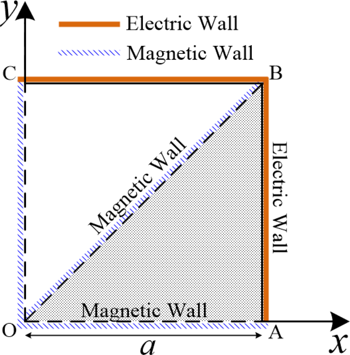
The proposed isosceles right triangular waveguide with one electric wall on one of its catheti (y = 0) and two magnetic walls on the other edges (y = x, x = a) supports the propagation of TE and TM modes. The cross section of the triangular waveguide is shown in Fig. 1. The mode functions can be constructed by proper linear superposition of mode solutions for the corresponding square waveguide [Reference Overfelt and White15] depicted in Fig. 1.
Cross section of an isosceles right triangular waveguide (AOB) with two magnetic walls and one electric wall in the corresponding square waveguide (AOCB) with two magnetic walls and two electric walls.
Square waveguide with two magnetic walls and two electric walls
The cross section (AOCB) of a square waveguide with two magnetic walls and two electric walls is shown in Fig. 1. TE and TM modes in this square waveguide can be obtained by solving the Helmholtz wave equations [Reference Pozar16], subject to the boundary conditions
 $${\rm TE\!:\;} \left\{ {\matrix{ \matrix{\left. {H_z} \right \vert _{x = 0} = 0,{\rm} \hfill \cr \left. {H_z} \right \vert _{y = 0} = 0, \hfill} \hfill \cr {\left. {H_x} \right \vert _{y = 0} = 0,{\rm} \left. {\displaystyle{{\partial {\kern 1pt} H_z} \over {\partial x}}} \right \vert _{y = 0} = 0,} \hfill \cr {\left. {H_y} \right \vert _{x = 0} = 0,{\rm} \left. {\displaystyle{{\partial {\kern 1pt} H_z} \over {\partial y}}} \right \vert _{x = 0} = 0,} \hfill \cr {\left. {E_x} \right \vert _{y = a} = 0,{\rm} \left. {\displaystyle{{\partial {\kern 1pt} H_z} \over {\partial y}}} \right \vert _{y = a} = 0,} \hfill \cr {\left. {E_y} \right \vert _{x = a} = 0,{\rm} \left. {\displaystyle{{\partial {\kern 1pt} H_z} \over {\partial x}}} \right \vert _{x = a} = 0.} \hfill \cr}} \right.$$
 $${\rm TM\!:\;} \left\{ {\matrix{ \matrix{\left. {E_z} \right \vert _{x = a} = 0, \hfill \cr \left. {E_z} \right \vert _{y = a} = 0, \hfill} \hfill \cr {\left. {E_x} \right \vert _{y = a} = 0,{\rm} \left. {\displaystyle{{\partial {\kern 1pt} E_z} \over {\partial x}}} \right \vert _{y = a} = 0,} \hfill \cr {\left. {E_y} \right \vert _{x = a} = 0,{\rm} \left. {\displaystyle{{\partial {\kern 1pt} E_z} \over {\partial y}}} \right \vert _{x = a} = 0,} \hfill \cr {\left. {H_x} \right \vert _{y = 0} = 0,{\rm} \left. {\displaystyle{{\partial {\kern 1pt} E_z} \over {\partial y}}} \right \vert _{y = 0} = 0,} \hfill \cr {\left. {H_y} \right \vert _{x = 0} = 0,{\rm} \left. {\displaystyle{{\partial {\kern 1pt} E_z} \over {\partial x}}} \right \vert _{x = 0} = 0.} \hfill \cr}} \right.$$
The solutions of H z and E z for the TEmn and the TMmn modes are reduced to
 $$\left\{ \matrix{{\rm TE}\!:\,\,H_z = A_{mn} \sin \displaystyle{{m\pi x} \over {2a}}\sin \displaystyle{{n\pi y} \over {2a}}e^{ - j\beta z}, \hfill \cr {\rm TM}\!:\,E_z = B_{mn} \cos \displaystyle{{m\pi x} \over {2a}}\cos \displaystyle{{n\pi y} \over {2a}}e^{ - j\beta z}, \hfill} \right.$$
where a is the width of the square waveguide, as shown in Fig. 1. A mn and B mn are arbitrary amplitude constants, and β is the propagation constant. m and n must be odd integers for both the TEmn and the TMmn modes.
Then the field components can be calculated using [Reference Pozar16]
 $${\rm TE\!:\;} \left\{ {\matrix{ {H_x = - \displaystyle{{\,j\beta} \over {k_c^2}} \displaystyle{{m\pi} \over {2a}}A_{mn} \cos \displaystyle{{m\pi x} \over {2a}}\sin \displaystyle{{n\pi y} \over {2a}}e^{ - j\beta z},} \hfill \cr {H_y = - \displaystyle{{\,j\beta} \over {k_c^2}} \displaystyle{{n\pi} \over {2a}}A_{mn} \sin \displaystyle{{m\pi x} \over {2a}}\cos \displaystyle{{n\pi y} \over {2a}}e^{ - j\beta z},} \hfill \cr {E_x = - \displaystyle{{\,j\omega \mu} \over {k_c^2}} \displaystyle{{n\pi} \over {2a}}A_{mn} \sin \displaystyle{{m\pi x} \over {2a}}\cos \displaystyle{{n\pi y} \over {2a}}e^{ - j\beta z},} \hfill \cr {E_y = \displaystyle{{\,j\omega \mu} \over {k_c^2}} \displaystyle{{m\pi} \over {2a}}A_{mn} \cos \displaystyle{{m\pi x} \over {2a}}\sin \displaystyle{{n\pi y} \over {2a}}e^{ - j\beta z},} \hfill \cr {E_z = 0.} \hfill \cr}} \right.$$
 $${\rm TM\!:\;} \left\{ {\matrix{ {E_x = \displaystyle{{\,j\beta} \over {k_c^2}} \displaystyle{{m\pi} \over {2a}}B_{mn} \sin \displaystyle{{m\pi x} \over {2a}}\cos \displaystyle{{n\pi y} \over {2a}}e^{ - j\beta z},} \hfill \cr {E_y = \displaystyle{{\,j\beta} \over {k_c^2}} \displaystyle{{n\pi} \over {2a}}B_{mn} \cos \displaystyle{{m\pi x} \over {2a}}\sin \displaystyle{{n\pi y} \over {2a}}e^{ - j\beta z},} \hfill \cr {H_x = - \displaystyle{{\,j\omega \varepsilon} \over {k_c^2}} \displaystyle{{n\pi} \over {2a}}B_{mn} \cos \displaystyle{{m\pi x} \over {2a}}\sin \displaystyle{{n\pi y} \over {2a}}e^{ - j\beta z},} \hfill \cr {H_y = \displaystyle{{\,j\omega \varepsilon} \over {k_c^2}} \displaystyle{{m\pi} \over {2a}}B_{mn} \sin \displaystyle{{m\pi x} \over {2a}}\cos \displaystyle{{n\pi y} \over {2a}}e^{ - j\beta z},} \hfill \cr {H_z = 0.} \hfill \cr}} \right.$$
where μ = μ 0μ r, and ε = ε 0ε r are the permeability and permittivity of the material inside the waveguide, respectively. 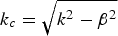 $k_c = \sqrt {k^2 - \beta ^2} $ is the cut-off wavenumber, and $k = \omega \sqrt {\mu \varepsilon} $ is the wavenumber of the dielectric material filling the waveguide.
Isosceles right triangular waveguide with two magnetic walls and one electric wall at one of its catheti
In the proposed isosceles right triangular waveguide, the mode functions subject to the boundary conditions can be obtained using appropriate linear combinations of TEmn or TMmn modes in the discussed square waveguide that have the same cut-off frequencies. The cross section (AOB) of the isosceles right triangular waveguide with two magnetic walls and one electric wall is shown in Fig. 1.
The mode function of H z for the TEmn mode
 $$\varphi _{mn} (x,y) = \sin \displaystyle{{m\pi x} \over {2a}}\sin \displaystyle{{n\pi y} \over {2a}} - \sin \displaystyle{{n\pi x} \over {2a}}\sin \displaystyle{{m\pi y} \over {2a}},$$
describes possible TE modes in the discussed square waveguide. Moreover, this mode function can meet the boundary conditions (7) present on the edges of the triangular waveguide, as shown in Fig. 1.
 $$\left\{ {\matrix{ {\left. {H_z} \right \vert _{y = 0} = 0,{\rm}} \hfill \cr {\left. {H_z} \right \vert _{y = x} = 0,} \hfill \cr {\left. {H_x} \right \vert _{y = 0} = 0,{\rm} \left. {\displaystyle{{\partial {\kern 1pt} H_z} \over {\partial x}}} \right \vert _{y = 0} = 0,} \hfill \cr {\left. {H_y} \right \vert _{y = x} = - \left. {H_x} \right \vert _{y = x}, {\rm} \left. {\left( {\displaystyle{{\partial {\kern 1pt} H_z} \over {\partial y}} + \displaystyle{{\partial {\kern 1pt} H_z} \over {\partial x}}} \right)} \right \vert _{y = x} = 0,} \hfill \cr {\left. {E_y} \right \vert _{x = a} = 0,{\rm} \left. {\displaystyle{{\partial {\kern 1pt} H_z} \over {\partial x}}} \right \vert _{x = a} = 0,} \hfill \cr}} \right.$$
where m and n must be odd integers, and m ≠ n. Thus, the TE mode that has the lowest cut-off frequency is the TE13 mode.
The field components for the TEmn modes can be obtained from (6) as
 $$\left\{ {\matrix{ \eqalign{H_x = & - \displaystyle{{\,j\beta} \over {k_c^2}} A_{mn} \cr &\times \left( {\displaystyle{{m\pi} \over {2a}}\cos \displaystyle{{m\pi x} \over {2a}}\sin \displaystyle{{n\pi y} \over {2a}} - \displaystyle{{n\pi} \over {2a}}\cos \displaystyle{{n\pi x} \over {2a}}\sin \displaystyle{{m\pi y} \over {2a}}} \right)e^{ - j\beta z},} \hfill \cr \eqalign{H_y = & - \displaystyle{{\,j\beta} \over {k_c^2}} A_{mn} \cr &\times \left( {\displaystyle{{n\pi} \over {2a}}\sin \displaystyle{{m\pi x} \over {2a}}\cos \displaystyle{{n\pi y} \over {2a}} - \displaystyle{{m\pi} \over {2a}}\sin \displaystyle{{n\pi x} \over {2a}}\cos \displaystyle{{m\pi y} \over {2a}}} \right)e^{ - j\beta z}, \cr H_z =\; & A_{mn} \cr &\times \left( {\sin \displaystyle{{m\pi x} \over {2a}}\sin \displaystyle{{n\pi y} \over {2a}} - \sin \displaystyle{{n\pi x} \over {2a}}\sin \displaystyle{{m\pi y} \over {2a}}} \right)e^{ - j\beta z},} \hfill \cr}} \right.$$
and
 $$\left\{ {\matrix{ \eqalign{E_x = & - \displaystyle{{\,j\omega \mu} \over {k_c^2}} A_{mn} \cr &\times \left( {\displaystyle{{n\pi} \over {2a}}\sin \displaystyle{{m\pi x} \over {2a}}\cos \displaystyle{{n\pi y} \over {2a}} - \displaystyle{{m\pi} \over {2a}}\sin \displaystyle{{n\pi x} \over {2a}}\cos \displaystyle{{m\pi y} \over {2a}}} \right)e^{ - j\beta z},} \hfill \cr \eqalign{E_y = & \displaystyle{{\,j\omega \mu} \over {k_c^2}} A_{mn} \cr &\times \left( {\displaystyle{{m\pi} \over {2a}}\cos \displaystyle{{m\pi x} \over {2a}}\sin \displaystyle{{n\pi y} \over {2a}} - \displaystyle{{n\pi} \over {2a}}\cos \displaystyle{{n\pi x} \over {2a}}\sin \displaystyle{{m\pi y} \over {2a}}} \right)e^{ - j\beta z}, \cr E_z = &\; 0.} \hfill \cr}} \right.$$
The mode function of E z for the TMmn modes
 $$\varphi _{mn} (x,\,y) = \cos \displaystyle{{m\pi x} \over {2a}}\cos \displaystyle{{n\pi y} \over {2a}} + \cos \displaystyle{{n\pi x} \over {2a}}\cos \displaystyle{{m\pi y} \over {2a}},$$
in the proposed square waveguide can satisfy the boundary conditions (11) of the discussed triangular waveguide when m and n are odd and integers. Hence, the TM mode that has the lowest cut-off frequency is the TM11 mode, which is, in fact, the dominant mode of this isosceles right triangular waveguide.
 $$\left\{ {\matrix{ {\left. {E_z} \right \vert _{x = a} \;= 0,} \hfill \cr {\left. {E_y} \right \vert _{x = a} \,= 0,\quad {\rm} \left. {\displaystyle{{\partial {\kern 1pt} E_z} \over {\partial y}}} \right \vert _{x = a} = 0,} \hfill \cr {\left. {H_x} \right \vert _{y = 0}\, = 0,\quad {\rm} \left. {\displaystyle{{\partial {\kern 1pt} E_z} \over {\partial y}}} \right \vert _{y = 0} = 0,} \hfill \cr {\left. {H_y} \right \vert _{y = x}\, = - \left. {H_x} \right \vert _{y = x},\; {\rm} \left. {\left( {\displaystyle{{\partial {\kern 1pt} E_z} \over {\partial x}} - \displaystyle{{\partial {\kern 1pt} E_z} \over {\partial y}}} \right)} \right \vert _{y = x} = 0.} \hfill \cr}} \right.$$
The field components for the TMmn modes can be found using (10)
 $$\left\{ {\matrix{ \eqalign{H_x =& \displaystyle{{\,j\omega \varepsilon} \over {k_c^2}} B_{mn} \cr &\times \left( { - \displaystyle{{n\pi} \over {2a}}\cos \displaystyle{{m\pi x} \over {2a}}\sin \displaystyle{{n\pi y} \over {2a}} - \displaystyle{{m\pi} \over {2a}}\cos \displaystyle{{n\pi x} \over {2a}}\sin \displaystyle{{m\pi y} \over {2a}}} \right)e^{ - j\beta z},} \hfill \cr \eqalign{H_y = & - \displaystyle{{\,j\omega \varepsilon} \over {k_c^2}} B_{mn} \cr &\times \left( { - \displaystyle{{m\pi} \over {2a}}\sin \displaystyle{{m\pi x} \over {2a}}\cos \displaystyle{{n\pi y} \over {2a}} - \displaystyle{{n\pi} \over {2a}}\sin \displaystyle{{n\pi x} \over {2a}}\cos \displaystyle{{m\pi y} \over {2a}}} \right)e^{ - j\beta z}, \cr H_z =&\; 0,} \hfill \cr}} \right.$$
and
 $$\left\{ {\matrix{ \eqalign{E_x = & - \displaystyle{{\,j\beta} \over {k_c^2}} B_{mn} \cr \times & \left( { - \displaystyle{{m\pi} \over {2a}}\sin \displaystyle{{m\pi x} \over {2a}}\cos \displaystyle{{n\pi y} \over {2a}} - \displaystyle{{n\pi} \over {2a}}\sin \displaystyle{{n\pi x} \over {2a}}\cos \displaystyle{{m\pi y} \over {2a}}} \right)e^{ - j\beta z},} \hfill \cr \eqalign{E_y = & - \displaystyle{{\,j\beta} \over {k_c^2}} B_{mn} \cr \times & \left( { - \displaystyle{{n\pi} \over {2a}}\cos \displaystyle{{m\pi x} \over {2a}}\sin \displaystyle{{n\pi y} \over {2a}} - \displaystyle{{m\pi} \over {2a}}\cos \displaystyle{{n\pi x} \over {2a}}\sin \displaystyle{{m\pi y} \over {2a}}} \right)e^{ - j\beta z}, \cr E_z =\; & B_{mn} \cr \times & \left( {\cos \displaystyle{{m\pi x} \over {2a}}\cos \displaystyle{{n\pi y} \over {2a}} + \cos \displaystyle{{n\pi x} \over {2a}}\cos \displaystyle{{m\pi y} \over {2a}}} \right)e^{ - j\beta z}.} \hfill \cr}} \right.$$
The cut-off frequencies of the TEmn and TMmn modes for the discussed isosceles right triangular waveguide are given by
 $$f_{c_{mn}} = \displaystyle{c \over {2\pi \sqrt {\varepsilon _r}}} \sqrt {\left( {\displaystyle{{m\pi} \over {2a}}} \right)^2 + \left( {\displaystyle{{n\pi} \over {2a}}} \right)^2}, $$
where  $c = 1/\sqrt {\mu _0 \varepsilon _0} $ is the speed of light, and ε r is the relative dielectric constant of the waveguide filling material.
The closed-form expressions of the field components for the dominant TM11 mode can be obtained from (12) and (13)
 $$\left\{ {\matrix{ {H_x = - \displaystyle{{\,j\omega \varepsilon \pi} \over {k_c^2 a}}B_{11} \cos \displaystyle{{\pi x} \over {2a}}\sin \displaystyle{{\pi y} \over {2a}}e^{ - j\beta z},} \hfill \cr \matrix{\!\!\!\!\!H_y = \displaystyle{{\,j\omega \varepsilon \pi} \over {k_c^2 a}}B_{11} \sin \displaystyle{{\pi x} \over {2a}}\cos \displaystyle{{\pi y} \over {2a}}e^{ - j\beta z}, \cr \!\!\!\!\!H_z = 0,\hfill } \cr }} \right.$$
and
 $$\left\{ {\matrix{ {E_x = \displaystyle{{\,j\beta \pi} \over {k_c^2 a}}B_{11} \sin \displaystyle{{\pi x} \over {2a}}\cos \displaystyle{{\pi y} \over {2a}}e^{ - j\beta z},} \hfill \cr\! \matrix{E_y = \displaystyle{{\,j\beta \pi} \over {k_c^2 a}}B_{11} \cos \displaystyle{{\pi x} \over {2a}}\sin \displaystyle{{\pi y} \over {2a}}e^{ - j\beta z}, \cr\!\!\!\!\!\!\!\!\! E_z = 2B_{11} \cos \displaystyle{{\pi x} \over {2a}}\cos \displaystyle{{\pi y} \over {2a}}e^{ - j\beta z}.} \hfill \cr}} \right.$$
The cut-off frequency of the TM11 mode is
 $$f_{c_{11}} = \displaystyle{{\sqrt 2 c} \over {4a\sqrt {\varepsilon _r}}}. $$
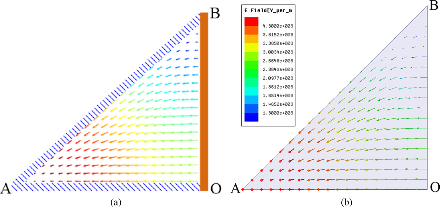
Figures 2(a) and 3(a) plot the electric and magnetic field lines for the dominant TM11 mode of the isosceles triangular waveguide, respectively. These plots are generated by analytical calculation using (15) and (16). The field lines obtained from electromagnetic simulation are shown in Figs 2(b) and 3(b). It can be seen that the simulated results are similar to the analytical ones. All propagating modes in this kind of triangular waveguide can be analytically calculated using the proposed equations. The first four propagating modes in the isosceles right triangular waveguide and their corresponding cut-off frequencies are listed in Table 1. Moreover, the equations can provide physical insight into the waveguide operation and be used to predict the characteristics and shapes of all propagating modes.
Electric field lines for the TM11 mode in the isosceles right triangular waveguide with two magnetic walls and one electric wall on a cathetus. (a) Analytically calculated electric field lines. (b) Simulated electric field lines.
Magnetic field lines for the TM11 mode in the isosceles right triangular waveguide with two magnetic walls and one electric wall on a cathetus. (a) Analytically calculated magnetic field lines. (b) Simulated magnetic field lines.

Cut-off frequencies of the first four propagating modes in the isosceles triangular waveguide.

Antenna design and results
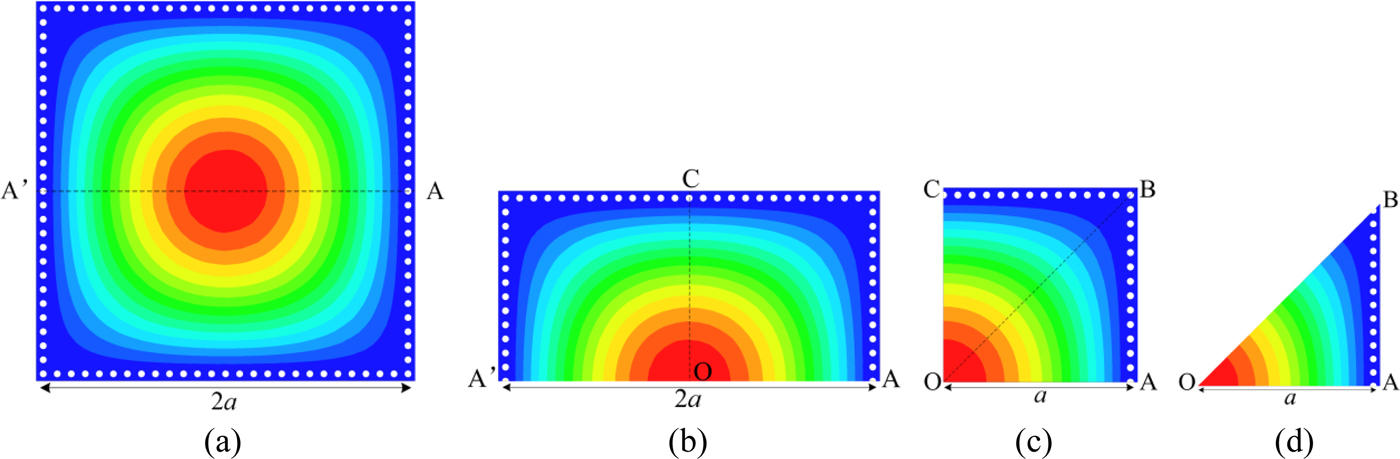
The short isosceles right triangular waveguide with two magnetic walls and one electric wall on a cathetus can be realized by the EMSIW, whereas the square waveguide with two magnetic walls and two electric walls shown in Fig. 1 can be realized by the QMSIW. The concept of the EMSIW starts from the square SIW. The evolution of the EMSIW from the square SIW is illustrated in Fig. 4. Figure 4(a) shows the simulated electric field distributions for the dominant mode in a square SIW. When the square SIW is cut along its fictitious magnetic wall AA′, a HMSIW is obtained, as shown in Fig. 4(b). Further bisecting the HMSIW along the fictitious magnetic wall OC, a QMSIW is realized, as shown in Fig. 4(c). In Fig. 4(d), an EMSIW is achieved by dividing the QMSIW along its fictitious magnetic wall OB.
Simulated electric field distributions for the dominant mode of (a) Square SIW, (b) HMSIW, (c) QMSIW, (d) EMSIW.
A metallic via-hole array in the EMSIW that connects its top and bottom plates can be regarded as an electric wall, while its two open sides are equivalent to the magnetic walls [Reference Deslandes and Wu17, Reference Lai18]. Because the height of EMSIW cavity is much smaller than its width, the resonant frequencies can be calculated using (14), and the dominant resonant mode of the EMSIW cavity is TM110 mode.
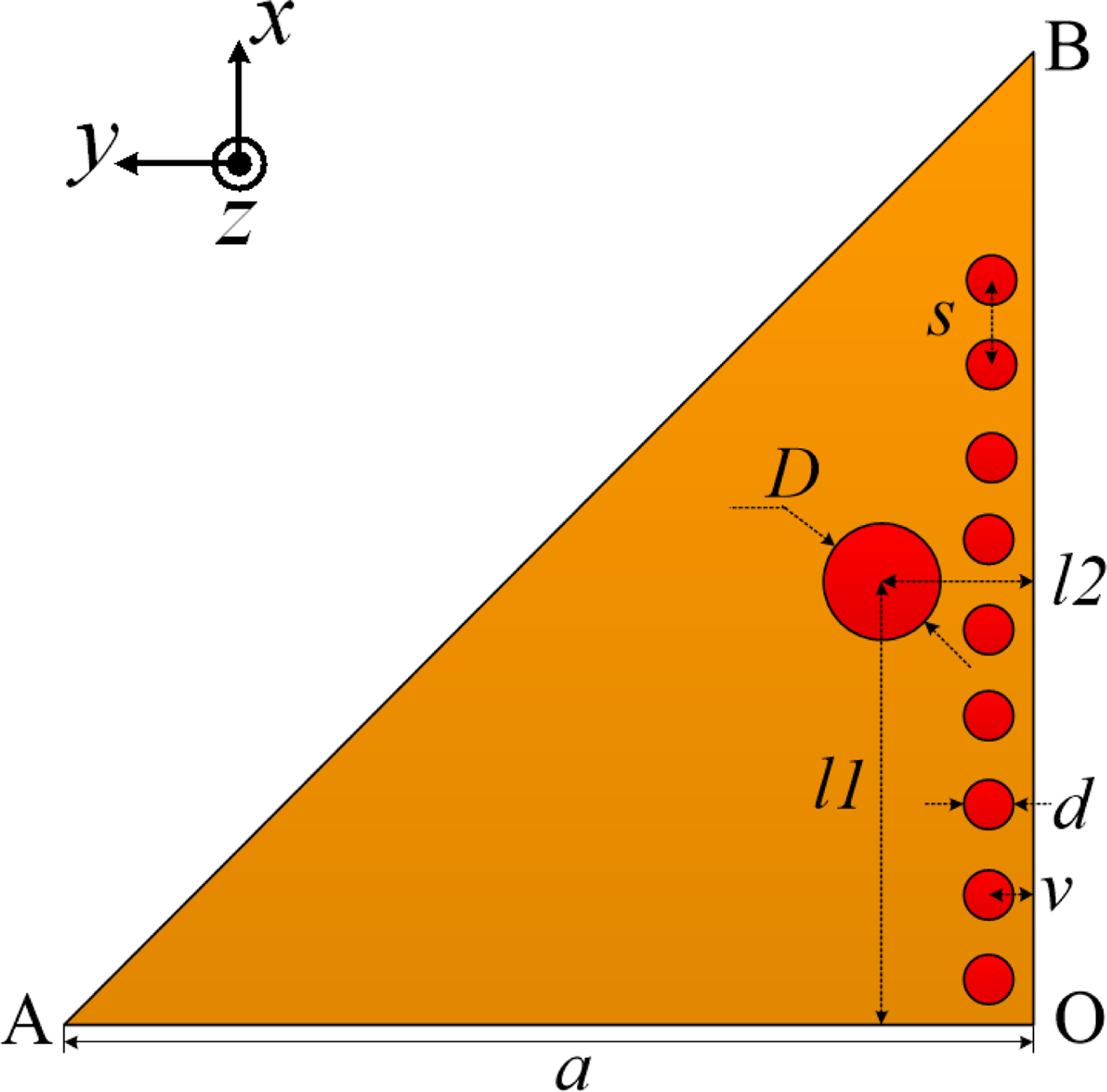
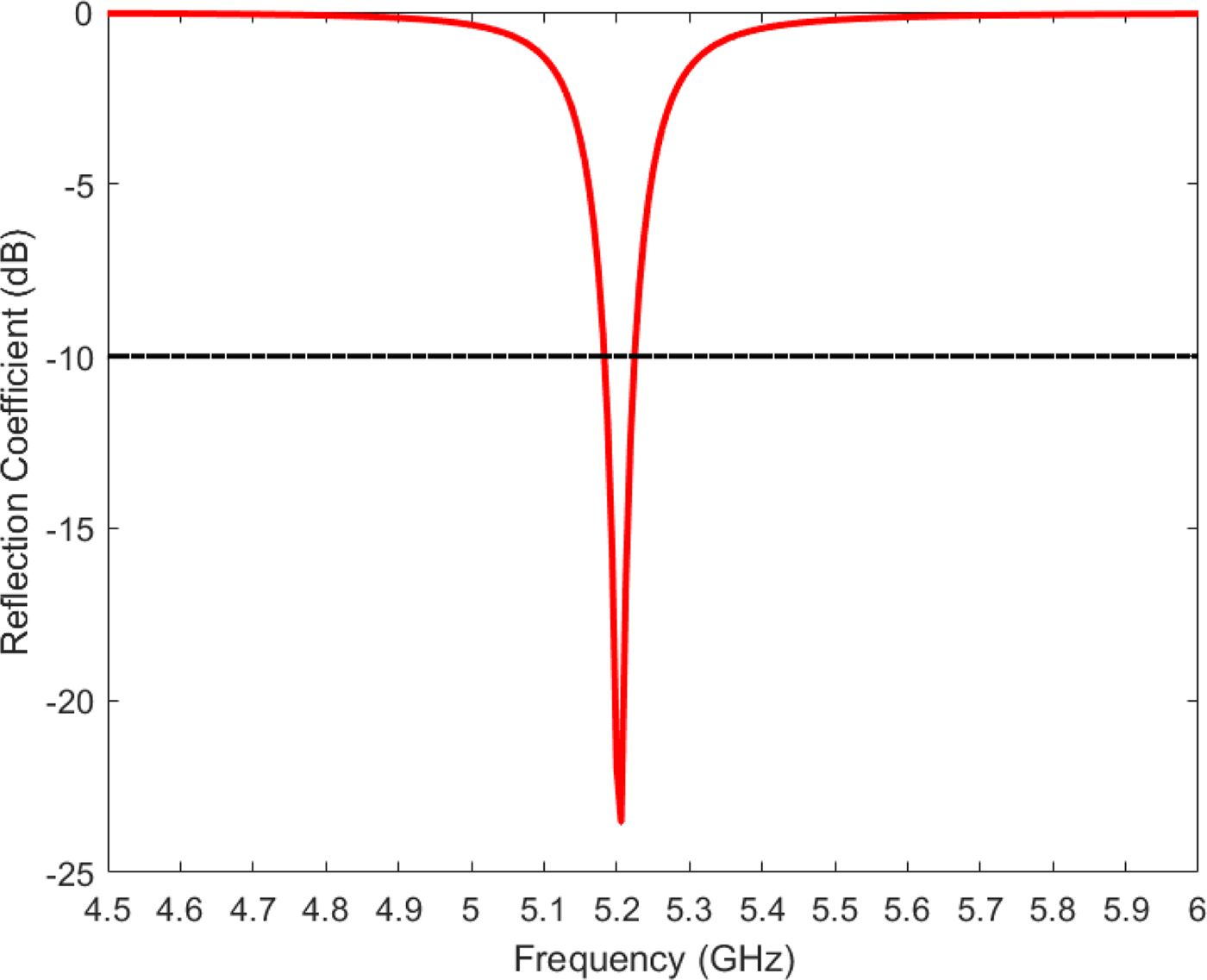
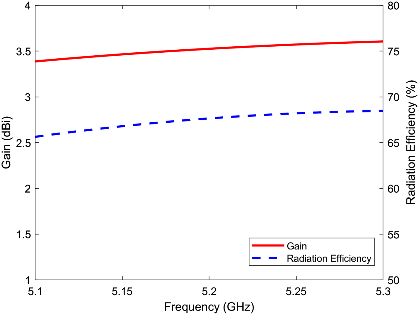
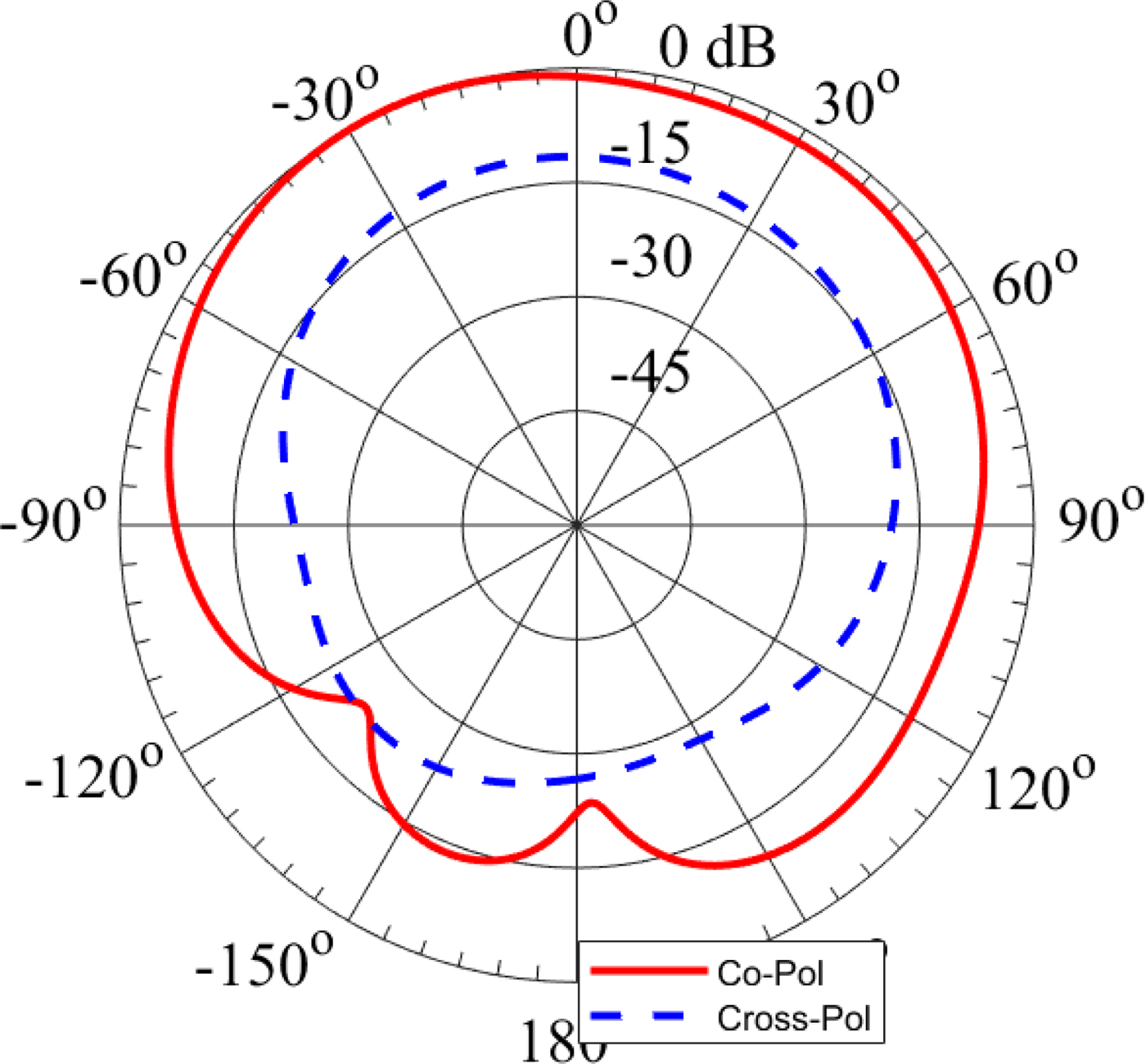
A linearly polarized antenna is designed with the aid of the equations derived from the theoretical analysis of the EMSIW. The geometry and parameters are shown in Fig. 5. A substrate Rogers RO4003 with dielectric constant ε r = 3.55, loss tangent tanδ = 0.0027, and thickness  $h = 0.813{\kern 1pt} \,{\rm mm}$ is chosen for the antenna design. The diameter of the via hole d is 0.5 mm, and the spacing between the centers of adjacent via holes s is 1 mm. The distance between the center of the via holes and the cathetus of the right triangular patch v is 0.5 mm. The length of the catheti of the right triangular patch is $a = 10.83\,{\kern 1pt} {\rm mm}$. A coaxial probe with a diameter $D = 1.26{\kern 1pt} \,{\rm mm}$ is used to feed the antenna at the location l 1 = 5.09 mm, l 2 = 1.68 mm. This feeding probe is realized using an Sub-Miniature A (SMA) connector. The simulated reflection coefficient of the designed linearly polarized EMSIW antenna is shown in Fig. 6. The simulated resonant frequency is 5.2 GHz, corresponding to the TM110 mode. The curves of simulated gain at broadside direction and radiation efficiency of the antenna as a function of frequency are illustrated in Fig. 7. The simulated gain at 5.2 GHz is 3.53 dBi, and the radiation efficiency is 67.65% at the same frequency. Figure 8 shows the simulated normalized radiation patterns of this antenna in the cut plane ϕ = 90° at 5.2 GHz.
Configuration of the linearly polarized eighth-mode substrate integrated waveguide antenna.
Simulated reflection coefficient of the linearly polarized eighth-mode substrate integrated waveguide antenna.
Simulated gain and radiation efficiency of the linearly polarized eighth-mode substrate integrated waveguide antenna.
Simulated radiation patterns of the linearly polarized eighth-mode substrate integrated waveguide antenna in the cut plane ϕ = 90° at 5.2 GHz.
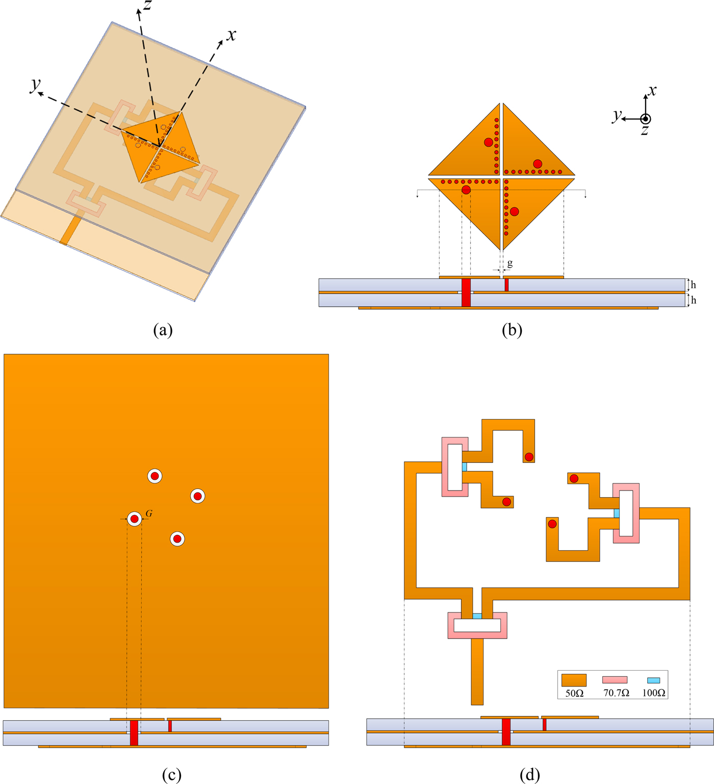
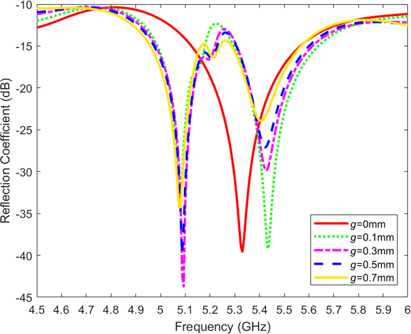
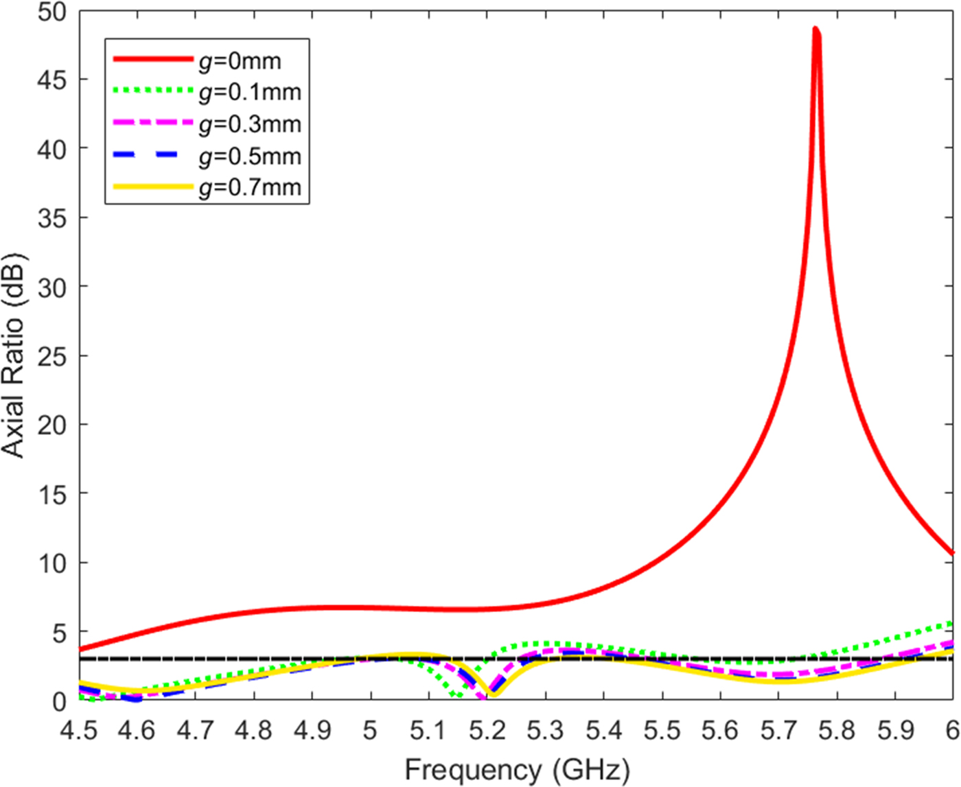
To achieve circular polarization, an antenna consisting of four linearly polarized EMSIW antennas and fed by a 90° power divider is proposed. The configuration of this antenna is obtained by sequentially rotating the linearly polarized EMSIW antenna, as shown in Fig. 9. The dimensions of each element of the CP antenna are the same as those of the previously designed linearly polarized antenna, which is shown in Fig. 5. Due to the array of metallic via holes on each of the triangular patches, the effect of the mutual coupling between each element is very small. The simulated reflection coefficients and axial ratios for different gaps g between each cell versus frequency are plotted in Figs 10 and 11, respectively. In order to achieve good radiation performance while miniaturizing the antenna, a spacing  $g = 0.5{\kern 1pt} \,{\rm mm}$ between each triangular patch is chosen. Feed-clearance disks of diameter $G = 2.31{\kern 1pt} \,{\rm mm}$ are etched on the ground plane around the feeding probes of diameter $D = 1.26{\kern 1pt} \,{\rm mm}$ for both the linearly polarized antenna and the CP antenna. A Wilkinson power divider network [Reference Guo19], which provides signals with 90° phase difference each other and equal power division at its output ports is used to feed the triangular patches, as illustrated in Fig. 9(d). The power divider is composed of $50{\kern 1pt} $ and $70.7\,{\kern 1pt} \Omega $ microstrip lines and three $100\,{\kern 1pt} \Omega $ isolation resistors. The widths of the $50{\kern 1pt} $ and $70.7{\kern 1pt} \Omega $ microstrip lines are 1.86 and 1.01 mm, respectively. Two layers of Rogers RO4003 substrate with the same thickness $h = 0.813{\kern 1pt} {\rm mm}$ are used to design the CP antenna. The size of the upper layer substrate is $52 \times 55{\kern 1pt} \,{\rm mm}^2 $, while the size of the lower layer substrate is $60 \times 55\,{\kern 1pt} {\rm mm}^2 $. The four isosceles right triangular patches are located on the top of the upper layer, and the power divider network is placed on the bottom of the lower layer. The ground plane of dimensions $60 \times 55{\kern 1pt} \,{\rm mm}^2 $ is placed between the two substrates.
Configuration of the designed circularly polarized eighth-mode substrate integrated waveguide antenna. (a) Three-dimensional model. (b) Radiator on the top layer. (c) Ground plane layer. (d) Power divider on the bottom layer.
Simulated reflection coefficients for different values of gap spacing g of the circularly polarized eighth-mode substrate integrated waveguide antenna.
Simulated axial ratios for different values of gap spacing g of the circularly polarized eighth-mode substrate integrated waveguide antenna.
The simulated electric current distributions on the triangular patches of the designed CP antenna at 5.2 GHz at different phases are shown in Fig. 12. It can be observed that there are two orthogonal current distributions with equal magnitude and 90° phase difference each other, and the electric current rotates in a clockwise direction, which generates a left-handed (LH) CP radiation. The simulated maximum electric field in the CP EMSIW antenna is 0.47 MV/m for an incident power of 1 W from 4.5 to 6 GHz. The breakdown threshold of the dielectric substrate is 31.2 MV/m, so the power capacity [Reference Guo20] of this antenna designed using Rogers RO4003 substrate with a thickness of 0.813 mm is 4.41 kW.
Simulated electric current distribution on the patch of the circularly polarized eighth-mode substrate integrated waveguide antenna at different phases of 5.2 GHz. (a) Phase = 30°. (b) Phase = 120°. (c) Phase = 210°. (d) Phase = 300°.

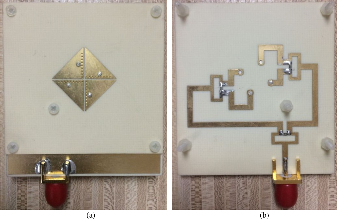
The proposed CP antenna is fabricated with the same dimensions illustrated in Fig. 9. Photographs of the fabricated CP EMSIW antenna are shown in Fig. 13. The simulated and measured reflection coefficients of the designed CP antenna are plotted in Fig. 14. It can be observed that the simulated curve is slightly shifted with respect to the measured one. This can be attributed to the tolerances of both the fabrication process and the material properties of the substrate. The measured reflection coefficient from 4.5 to 6 GHz is below −10 dB.
Photographs of the fabricated CP EMSIW antenna. (a) Radiator on the top layer. (b) Power divider on the bottom layer.
Simulated and measured reflection coefficients of the circularly polarized eighth-mode substrate integrated waveguide antenna.
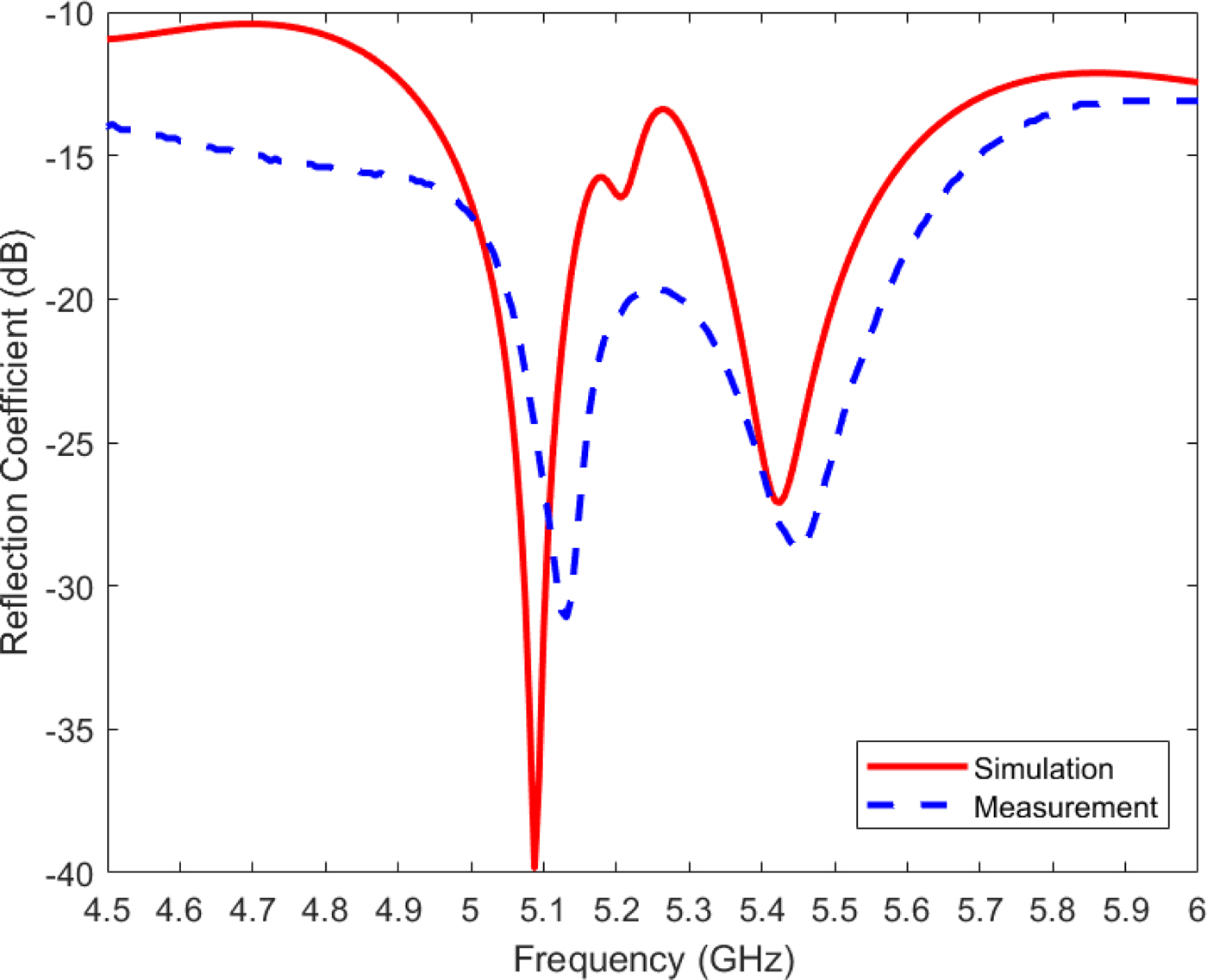
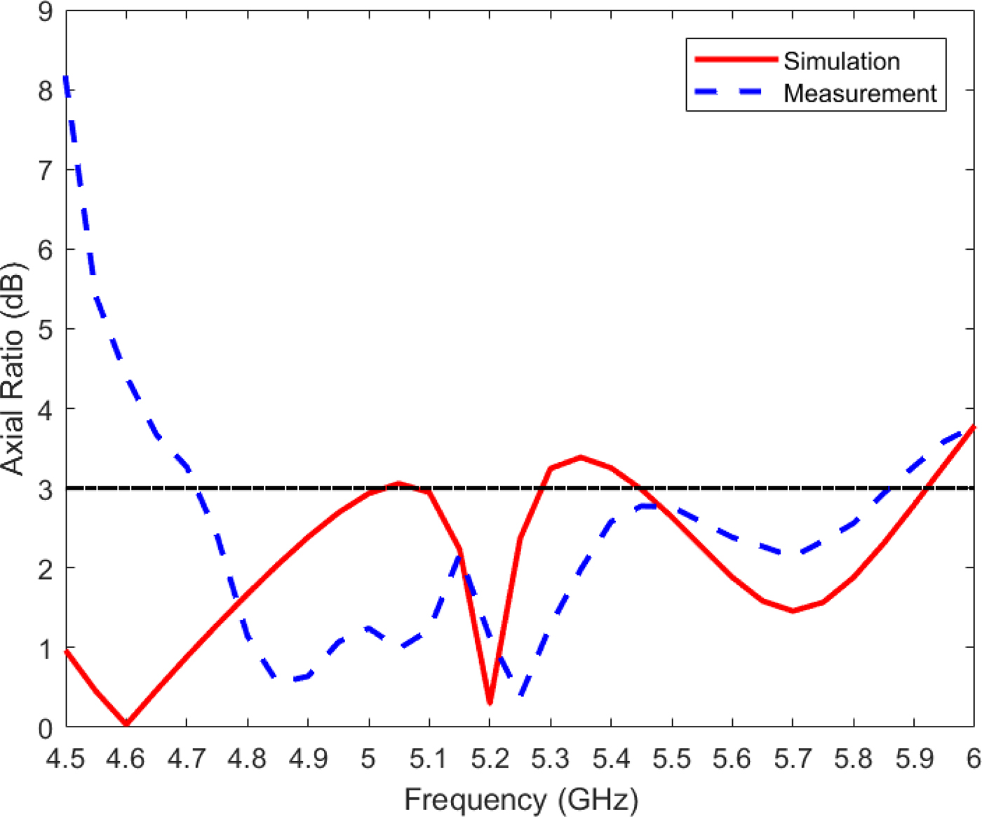
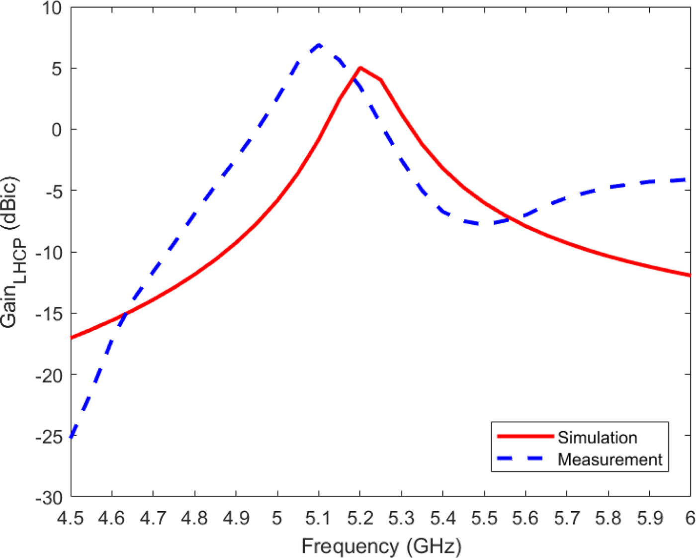
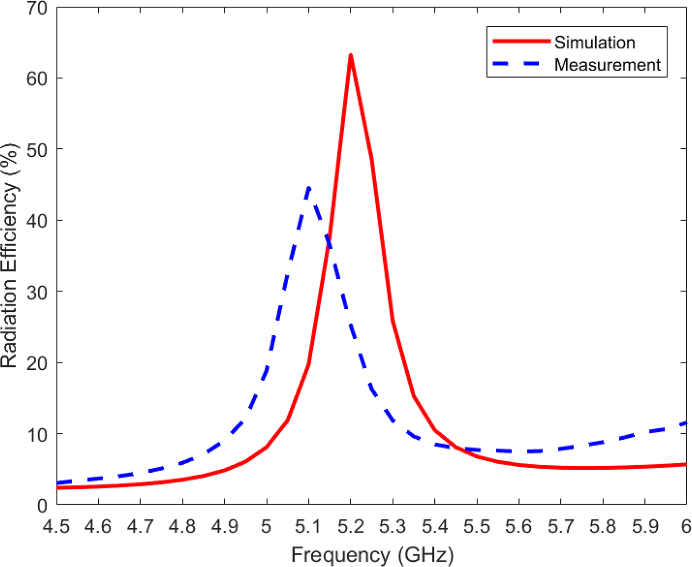
Figure 15 shows the simulated and measured axial ratios of the proposed CP antenna at broadside direction. The measured 3-dB axial ratio bandwidth is 21.6% achieved from 4.72 to 5.86 GHz. The simulated and measured LHCP gains at broadside are plotted in Fig. 16, and the simulated and measured radiation efficiencies are shown in Fig. 17. The measured maximum gain and radiation efficiency are 6.89 dBic and 44.57% at 5.1 GHz, respectively. Figures 16 and 17 also show that the values of measured gain and radiation efficiency at 5.2 GHz are 3.46 dBic and 25.22%, respectively. The discrepancies observed between the measured and simulated results can be attributed to losses from the SMA connector, conductive and dielectric losses from the materials that are employed for the designed antenna, and uncertainties related to the fabrication process and material tolerances.
Simulated and measured axial ratios of the circularly polarized eighth-mode substrate integrated waveguide antenna.
Simulated and measured gains at broadside of the circularly polarized eighth-mode substrate integrated waveguide antenna.
Simulated and measured radiation efficiencies of the circularly polarized eighth-mode substrate integrated waveguide antenna.
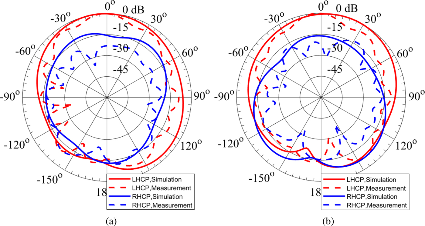
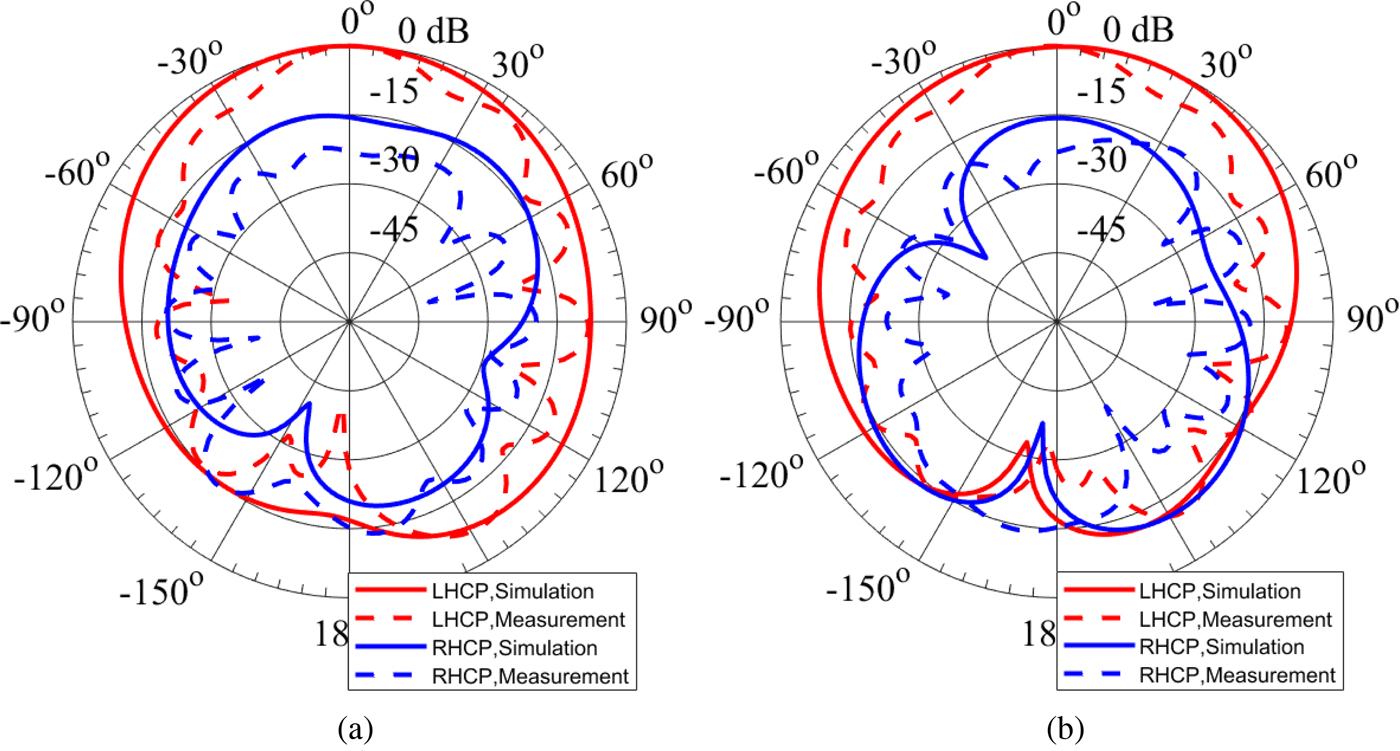
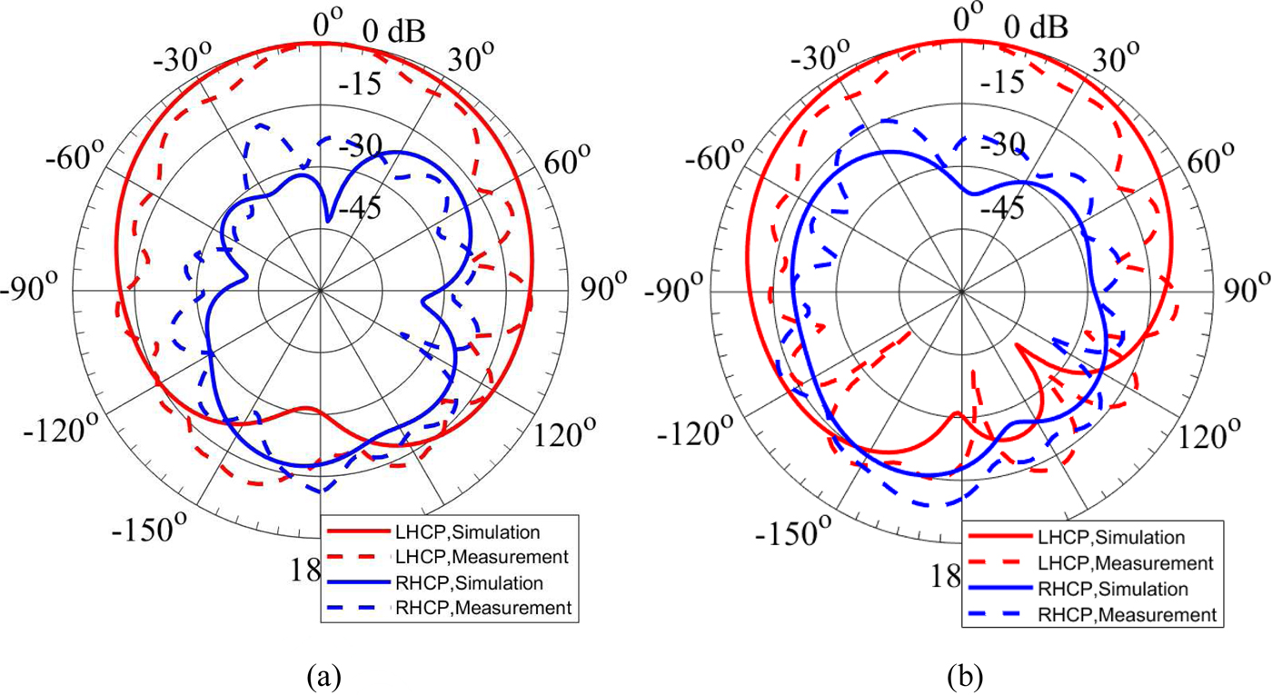
The simulated and measured normalized radiation patterns of the antenna at three different frequencies in the operating band in cut planes ϕ = 0° (xz-plane) and ϕ = 90° (yz-plane) are illustrated in Figs 18–20. Figure 18 shows the normalized radiation patterns at 5 GHz. At this frequency, the measured LHCP gain of the antenna at broadside direction is 2.54 dBic. The normalized radiation patterns at 5.1 and 5.2 GHz are plotted in Figs 19 and 20, respectively. The discrepancies between the measured and simulated radiation patterns can be attributed to the tolerances of the material properties of the substrate, fabrication process, and the additional radiation from the cables used in the measurement [Reference Foged21, Reference Liu22]. The measured front-to-back ratio of the proposed CP EMSIW antenna is 15.84 dB at 5 GHz, 27.76 dB at 5.1 GHz, and 18.91 dB at 5.2 GHz.
Simulated and measured radiation patterns of the circularly polarized eighth-mode substrate integrated waveguide antenna at 5 GHz. (a) Cut plane ϕ = 0°. (b) Cut plane ϕ = 90°.
Simulated and measured radiation patterns of the circularly polarized eighth-mode substrate integrated waveguide antenna at 5.1 GHz. (a) Cut plane ϕ = 0°. (b) Cut plane ϕ = 90°.
Simulated and measured radiation patterns of the circularly polarized eighth-mode substrate integrated waveguide antenna at 5.2 GHz. (a) Cut plane ϕ = 0°. (b) Cut plane ϕ = 90°.
A comparison between the proposed CP EMSIW antenna and previously reported antennas is presented in Table 2. The radiator area is calculated relative to the free space wavelength λ 0 at the corresponding operating frequencies. It can be seen that the designed planar CP EMSIW antenna is able to present a larger bandwidth with a higher gain using a smaller radiator.
Performance comparison between the proposed antenna and previously reported antennas.

ARBW, Axial ratio bandwidth; RLBW, Return loss bandwidth; λ 0, Free space wavelength.
Conclusion
A model of the isosceles right triangular waveguide with one electric and two magnetic walls and its corresponding square waveguide are proposed to analyze the properties of the EMSIW. Closed-form expressions for the electromagnetic field components and cut-off frequencies, which can be applied to analyze all propagating modes in this triangular waveguide, are derived. The analytically calculated electromagnetic field distribution in the EMSIW for its dominant mode is in very good agreement with the simulated results. A broadband compact planar CP antenna based on the EMSIW is designed. The measured 3-dB axial ratio bandwidth is 21.6%, and the reflection coefficient within the operating frequency range is below −10 dB. The measured peak LHCP gain at broadside is 6.89 dBic at 5.1 GHz. Both the simulated and the experimental results indicate that the designed antenna can achieve a good radiation performance using a compact radiator.
 Ni Wang received the B.S. degree in Communication Engineering from Beijing Information Science and Technology University, Beijing, China, in 2010. She is currently pursuing the Ph.D. degree in Electronic Science and Technology at Beijing Institute of Technology, Beijing, China. Her current research interests include antenna theory and design, and EM field theory.
 Xiaowen Xu received the Ph.D. degree in Electrical Engineering from the University of Electronic Science and Technology of China, Chengdu, China, in 1989. He has been with the Department of Electronic Engineering, Beijing Institute of Technology, Beijing, China, since 1992, where he is currently a Professor. His current research interests include antenna theory and technology, EM scattering, and computational electromagnetics.


 Open access

