


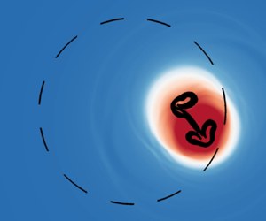



1. Introduction
Cavitation erosion is prevalent in applications such as fuel injectors, propellers, therapeutic ultrasound and ultrasonic cleaning. In hydrodynamic applications, cavitation-induced pitting damages solid surfaces and may constitute a lifetime-limiting factor (Blake & Gibson Reference Blake and Gibson1987). For example, cavitation erosion poses design constraints on the mercury target vessel and proton-beam power limitations in the Spallation Neutron Source (Haines et al. Reference Haines, McManamy, Gabriel, Battle, Chipley, Crabtree, Jacobs, Lousteau, Rennich and Riemer2014; Riemer et al. Reference Riemer, McClintock, Kaminskas and Abdou2014; Winder, Lin & Mach Reference Winder, Lin and Mach2021). Applications such as diesel injector nozzles (Chaves et al. Reference Chaves, Knapp, Kubitzek, Obermeier and Schneider1995; Gavaises et al. Reference Gavaises, Papoulias, Andriotis, Giannadakis and Theodorakakos2007; Giannadakis, Gavaises & Arcoumanis Reference Giannadakis, Gavaises and Arcoumanis2008), hydraulic turbines (Escaler et al. Reference Escaler, Egusquiza, Farhat, Avellan and Coussirat2006; Brijkishore, Khare & Prasad Reference Brijkishore and Prasad2021) and hydrofoils (Patella, Archer & Flageul Reference Patella, Archer and Flageul2012; Venning, Pearce & Brandner Reference Venning, Pearce and Brandner2022) have also observed degradation in performance due to cavitation erosion. In some cases, the cavitating bubble can form near a solid boundary within the boundary layer or may be submerged in a mean shear flow. For example, in ultrasonic cleaning applications, the ultrasonic waves can result in acoustic streaming, which results in travelling cavitation bubbles that can remove contaminants with a greater efficiency (Kim et al. Reference Kim, Kim, Choi and Kim2009; Shchukin et al. Reference Shchukin, Skorb, Belova and Möhwald2011; Kim et al. Reference Kim, Chahine, Franc and Karimi2014; Ando, Sugawara & Sakota Reference Ando, Sugawara and Sakota2021). Ceccio & Brennen (Reference Ceccio and Brennen1991) and De Chizelle, Ceccio & Brennen (Reference De Chizelle, Ceccio and Brennen1995) experimentally observed travelling cavitation bubbles over standard head forms where hemispherical cavitation bubbles deform into wedge-like shapes due to the interaction of the bubbles with the flow, which shears the bubble and fragments it into smaller bubbles, resulting in multiple collapses. These additional albeit weaker collapses generate noise and extent of damage to the surface. Dular et al. (Reference Dular, Požar, Zevnik and Petkovšek2019) examined a single bubble collapsing near a surface in a homogeneous velocity field ( $5\,{\rm m}\,{\rm s}^{-1}$) parallel to the adjacent surface. The shear flow deflects the re-entrant jet in the shear flow direction, resulting in an asymmetric splash of the collapsing bubble onto the neighbouring wall. The deflected re-entrant jet was reported to be the primary damage mechanism for a bubble initially detached and located a finite distance from the wall.
The collapse of a bubble is the central problem of cavitation erosion. Rayleigh (Reference Rayleigh1917) demonstrated that a spherical cavity imploding in an infinite, initially stationary fluid produces high pressures in the liquid. Upon collapse, energy is released as a shock propagating radially outward, which can damage neighbouring materials (Plesset Reference Plesset1949). The shock produced at collapse plays an essential role in cavitation erosion (Hickling & Plesset Reference Hickling and Plesset1964). Early experiments showed that the presence of a wall leads to asymmetry, resulting in an axisymmetric collapse (Naudé & Ellis Reference Naudé and Ellis1961; Benjamin & Ellis Reference Benjamin and Ellis1966; Gibson Reference Gibson1968). During the collapse, the bubble migrates towards the wall due to the attraction from the image bubble. The axisymmetric collapse is characterised by the formation of a re-entrant jet directed towards the wall. This jet originates from the bubble interface furthest from the wall, penetrates the bubble, accelerates up to several hundred metres and impinges on the opposite bubble side (Plesset & Chapman Reference Plesset and Chapman1971; Lauterborn & Bolle Reference Lauterborn and Bolle1975; Philipp & Lauterborn Reference Philipp and Lauterborn1998). Jet impingement produces an outward propagating shock. Soon after the production of this water-hammer shock, the bubble continues imploding, reaches minimum volume and produces an implosion shock (Supponen et al. Reference Supponen, Obreschkow, Kobel, Tinguely, Dorsaz and Farhat2017). If the bubble is sufficiently close to the wall, then it may directly impinge upon the wall. However, experimental efforts to relate material damage to the shock pressure and jet impingement on the wall via experiments or theory have proven to be challenging due to the presence of a wide range of spatio-temporal scales (Hickling & Plesset Reference Hickling and Plesset1964; Shutler & Mesler Reference Shutler and Mesler1965; Gonzalez-Avila, Denner & Ohl Reference Gonzalez-Avila, Denner and Ohl2021).
Numerical simulations have provided further insights into the bubble collapse near a wall. Early studies used potential flow to examine the re-entrant jet formation (Benjamin & Ellis Reference Benjamin and Ellis1966; Plesset & Chapman Reference Plesset and Chapman1971). The shape evolution and re-entrant jet velocity results agreed well with experimental observations made by Benjamin & Ellis (Reference Benjamin and Ellis1966) and Lauterborn & Bolle (Reference Lauterborn and Bolle1975). However, these methods consider the liquid to be incompressible and, therefore, are unable to capture the shocks produced during the collapse and their interaction with the nearby rigid wall. Johnsen & Colonius (Reference Johnsen and Colonius2009) numerically solved the Euler equations with a finite-volume method using an interface-capturing approach and achieved good agreement with the experimental collapse time (Lindau & Lauterborn Reference Lindau and Lauterborn2003) and wall pressure (Shima, Tomita & Takahashi Reference Shima, Tomita and Takahashi1984) for different initial stand-off distances. Beig (Reference Beig2018) examined the collapse morphology, dynamics and maximum wall pressures produced by the axisymmetric collapse at various initial stand-off distances. The work showed that the driving pressure across the bubble interface and initial stand-off distance from the rigid boundary determine the bubble collapse time and morphology of the re-entrant jet, respectively. Results agreed with the experimental bubble shape evolution (Philipp & Lauterborn Reference Philipp and Lauterborn1998), re-entrant jet speed (Brujan et al. Reference Brujan, Keen, Vogel and Blake2002; Supponen et al. Reference Supponen, Obreschkow, Tinguely, Kobel, Dorsaz and Farhat2016) and maximum pressure decay (Cole Reference Cole1948). These methods have also been used to study the bubble collapse dynamics and pressures at surfaces near a vessel (Coralic & Colonius Reference Coralic and Colonius2013), corner (White, Beig & Johnsen Reference White, Beig and Johnsen2023) and crevice (Trummler et al. Reference Trummler, Bryngelson, Schmidmayer, Schmidt, Colonius and Adams2020).
A limited number of numerical investigations have been conducted on the cavitation dynamics in a shear flow. Two distinct bubble collapse morphologies are observed in simulations: (i) re-entrant jet deflection, also observed experimentally by Dular et al. (Reference Dular, Požar, Zevnik and Petkovšek2019), and (ii) shear-induced converging jets. Yu, Ceccio & Tryggvason (Reference Yu, Ceccio and Tryggvason1995) numerically simulated a bubble collapse in a shear flow at a driving pressure of  $50\,{\rm kPa}$ to investigate interactions with the boundary layer. As the shear rate increases, the re-entrant jet becomes smaller, and the jet impact location moves further downstream in the flow direction. Additionally, as the shear flow velocity approaches the characteristic re-entrant jet speed, the bubble collapse rate increases and approaches the inviscid, no-shear limit. Dabiri, Sirignano & Joseph (Reference Dabiri, Sirignano and Joseph2010) and Chen (Reference Chen2010) considered bubble collapse in a flow generated by two shearing plates and observed the bubble deforming into an ellipsoid shape. High-pressure regions near the major axis of the ellipsoid were observed, followed by the emergence of a concave shape on the surface of the bubble. Dabiri et al. (Reference Dabiri, Sirignano and Joseph2010) reported the formation of re-entrant jets along the minor axis of the ellipsoid, which impact the bubble interface, resulting in vapour entrapment and the formation of ‘satellite bubbles’. Although these studies examined the effect of initial shear rates and stand-off distances on the bubble shape morphology, these simulations could not represent shock wave generation and propagation, as they consider semi-incompressible fluid flow with only the gas being compressible.
This work aims to investigate the competing effect between inertia and shear on the collapse of a gas bubble in a shear flow near a rigid wall. By varying the initial shear rate and stand-off distance from the wall in our numerical simulations, we examine the bubble morphologies and characterise the outward-propagating shock impingement on the nearby wall and the resulting maximum wall pressure at the wall. The manuscript is organised as follows. In § 2, the problem set-up is presented. The governing equations and numerical solver are then discussed. In § 3, we compare the bubble collapse dynamics and maximum wall pressures for different shear rates and stand-off distances. We provide our conclusions in § 4.
2. Problem set-up and governing equations
Figure 1 illustrates our problem set-up. We consider a linear shear flow near an infinitely long, flat rigid wall with an initially spherical gas bubble of radius  $R_o$ surrounded by water of density $\rho _l$, pressure $p_{\infty }$ and temperature $T_{\infty }$ and placed at a distance of $z_{o}$ from the wall. In practical applications, bubbles can grow from ${O}(1)$ to ${O}(10^2)\,\mathrm {\mu }{\rm m}$, resulting in a non-spherical shape and non-uniform pressure distribution due to the presence of the rigid wall and shear (Dabiri et al. Reference Dabiri, Sirignano and Joseph2010; Tiwari, Pantano & Freund Reference Tiwari, Pantano and Freund2015; Dular et al. Reference Dular, Požar, Zevnik and Petkovšek2019; Gonzalez-Avila et al. Reference Gonzalez-Avila, Denner and Ohl2021). To study the effect of shear and distance from the wall solely on the bubble collapse dynamics, we initialise with an initial radius $R_o=500\,\mathrm {\mu }{\rm m}$ for all the cases. Thus comparing similar bubble collapses. This initially spherical gas bubble has an equivalent volume to the bubbles after growth, thus considering the equivalent volume after vapour condensation and ignoring surface tension effects (Lauterborn et al. Reference Lauterborn, Lechner, Koch and Mettin2018; Gonzalez-Avila et al. Reference Gonzalez-Avila, Denner and Ohl2021). Bubbles of similar radius have been studied experimentally (Dular et al. Reference Dular, Požar, Zevnik and Petkovšek2019; Gonzalez-Avila et al. Reference Gonzalez-Avila, Denner and Ohl2021) and numerically investigated (Yu et al. Reference Yu, Ceccio and Tryggvason1995; Beig, Aboulhasanzadeh & Johnsen Reference Beig, Aboulhasanzadeh and Johnsen2018; Bußmann et al. Reference Bußmann, Riahi, Gökce, Adami, Barcikowski and Adams2023). The initial non-dimensional stand-off distance is $\gamma _{o} = z_{o} / R_{o}$. The bubble contains vapour, which is modelled as a non-condensable ideal gas with pressure $p_{o}=3550\,{\rm Pa}$ and temperature $T_o = 300\,{\rm K}$. The initial liquid pressure $p_{\infty } = 5\,{\rm MPa}$ is considered, motivated by the studies of Franc et al. (Reference Franc, Riondet, Karimi and Chahine2011), who identify it as relevant for cavitation erosion applications; we define $\Delta p = p_{\infty } - p_o$. The shear across the bubble is $\dot {\varsigma }_o = ((u_{x})_{\gamma _{o}+1}-(u_{x})_{\gamma _{o}-1})/2R_{o}$, where $(u_{x})_{\gamma _{o}+1}$ and $(u_x)_{\gamma _o -1}$ are the $x$-components of the velocity at the top of the bubble (farthest from the wall) and bottom of the bubble (closest to the wall), respectively. A symmetry boundary condition is used along the $xz$-centreplane. The slip non-reflecting boundary conditions of Thompson (Reference Thompson1990) are used at the top boundary to enforce the top plate velocity corresponding to the desired shear rate. A perfectly reflecting, no-slip boundary condition represents the rigid wall. The left, right and back boundaries are non-reflective boundary conditions. The computational domain has size $8R_o\times 4R_o\times 6R_o$. Beig (Reference Beig2018) showed that $128$ computational cells per initial bubble radius can resolve the maximum wall pressure due to inertia-driven collapse. Previous studies (Yu et al. Reference Yu, Ceccio and Tryggvason1995; Dabiri et al. Reference Dabiri, Sirignano and Joseph2010; Dular et al. Reference Dular, Požar, Zevnik and Petkovšek2019) have shown that bubble collapse under shear flow results in a larger bubble surface area and, therefore, in the present study, $128$ cells per initial bubble radius is considered sufficient resolution.
Schematic of an initially spherical gas bubble of radius  $R_{o}$ in a shear flow located at a distance $z_{o}$ away form a rigid, flat wall. The $y$-axis direction points out of the page and $x_o$ is the wall centreline location, $x=0$.

We perform direct simulations of the Navier–Stokes equations with the five-equation multiphase model (Kapila et al. Reference Kapila, Menikoff, Bdzil, Son and Stewart2001), where pressure and velocity equilibria between the phases are assumed. This model and its improvements have been widely applied to study a range of phenomena (Allaire, Clerc & Kokh Reference Allaire, Clerc and Kokh2002; Murrone & Guillard Reference Murrone and Guillard2005; Perigaud & Saurel Reference Perigaud and Saurel2005; Petitpas et al. Reference Petitpas, Massoni, Saurel, Lapebie and Munier2009; Beig Reference Beig2018; Yang et al. Reference Yang, Liu, Wan and Hu2021; Rodriguez et al. Reference Rodriguez, Beig, Barbier and Johnsen2022; Bidi et al. Reference Bidi, Shams, Koukouvinis and Gavaises2023; Yang et al. Reference Yang, Liu, Li, Zhao and Hu2023). We solve the mass conservation, momentum and energy balance equations in the absence of gravity
 \begin{gather} \frac{\partial \rho}{\partial t} + \frac{\partial }{\partial x_j}(\rho u_j)= 0, \end{gather}
 \begin{gather}\frac{\partial }{\partial t} (\rho^{(1)} \alpha^{(1)}) + \frac{\partial }{\partial x_j} (\rho^{(1)} \alpha^{(1)} u_j)= 0, \end{gather}
 \begin{gather}\frac{\partial }{\partial t} (\rho u_i) + \frac{\partial }{\partial x_j}(\rho u_i u_j + p\delta_{ij}) = \frac{\partial \tau_{ij}}{\partial x_j}, \end{gather}
 \begin{gather}\frac{\partial E}{\partial t} + \frac{\partial}{\partial x_j}((E + p) u_j) = \frac{\partial}{\partial x_k}(u_i \tau_{ik} - Q_k), \end{gather}
where  $\rho$ is the total (mixture) density, $u_i$ the velocity vector, $Q_k$ the heat flux, $\alpha ^{(1)}$ the volume fraction of water and we use indices $i,j = 1, 2$ and $3$; repeated indices denote summation. Equation (2.1b) is the mass conservation equation for the water component. The total energy per unit volume $E$ comprises internal and kinetic contributions: $E = \rho e + \tfrac {1}{2} \rho u_k^2$. An additional species transport equation is solved for $\alpha ^{(k)}$ in non-conservative form to maintain interfacial equilibrium conditions for velocity, pressure and temperature (Beig & Johnsen Reference Beig and Johnsen2015).
The Noble–Abel stiffened-gas equation of state of Le Métayer & Saurel (Reference Le Métayer and Saurel2016) is used to relate the internal energy to pressure
 \begin{equation} \rho (e-q) = \frac{p (1-\rho b)}{n-1} + \frac{n B (1-\rho b)}{n-1}, \end{equation}
where  $q$,
$q$,  $n$,
$n$,  $B$ and $b$ are material constants prescribed to produce the correct propagation speeds in water. Table 1 lists the properties of liquid water and water vapour. Fourier conduction describes the heat diffusion process: $Q_i = - \kappa \partial T/\partial x_i$, where $\kappa$ is the thermal conductivity. Fluids behave in a Newtonian fashion, such that the viscous stress is given by $\tau _{ij} = \mu _b \dot {\epsilon }_{kk}\delta _{ij} + \mu _s \dot {\epsilon }_{ij}^{(d)}$, where $\mu _b$ is the bulk viscosity, $\mu _s$ the shear viscosity and $\dot {\epsilon }_{ij}$ the strain-rate tensor with $\dot {\epsilon }_{ij}^{(d)}$ as its deviatoric part. For water vapour, $\kappa = 0.02\,{\rm W}\,({\rm m}\,{\rm K})^{-1}$ and $\mu _b = \mu _s = 10^{-5}\,{\rm Pa}\,{\rm s}$; for liquid water, $\kappa = 0.6\,{\rm W}\,({\rm m}\,{\rm K})^{-1}$ and $\mu _b = \mu _s = 9\times 10^{-4}\,{\rm Pa}\,{\rm s}$. Based on the characteristic speed $u_c = \sqrt {\Delta p/\rho _l}$ defined by Plesset & Chapman (Reference Plesset and Chapman1971) and $R_o$, the Reynolds number is of ${O}(10^4)$ such that the flow is inertia driven and the bulk viscosity would have negligible effects. Thus, bulk viscosity is assumed to be identical to the shear viscosity for numerical convenience. For the characteristic speed and $R_o$, the estimated Weber number is $3.4\times 10^4$. Using the shear velocity at the top domain boundary, the Weber numbers range between $1.9\times 10^4$ and $3\times 10^5$. For such large Weber numbers, surface tension has negligible influence and, therefore, can be neglected. Since the bubble collapses under consideration are inertia or shear dominated, mass transfer (Beig Reference Beig2018) and phase change (Storey & Szeri Reference Storey and Szeri2000; Preston Reference Preston2004) can be neglected. We use the numerical approach presented by Beig & Johnsen (Reference Beig and Johnsen2015) to solve the resulting set of equations.
Constants in the Noble–Abel stiffened-gas equation of state for water.

Three non-dimensional parameters govern the problem: the initial driving pressure  $p_{\infty }/\rho _l a_l (\Delta p/\rho _l)^{1/2}$, stand-off distance $\gamma _{o}=z_o/R_o$ and shear rate $\omega _{o} = 2\dot {\varsigma }_o R_{o} / u_c$. Our focus is on the latter two parameters to understand the role of shear on the wall pressure produced by bubble collapse with different initial stand-off distances. As a baseline, we consider $\gamma _o = 3/2$ (as done by Yu et al. Reference Yu, Ceccio and Tryggvason1995) and $\omega _o = 1/2$. As illustrated in figure 2 and tabulated in table 2, we vary $\omega _o$ and $\gamma _o$ to understand the effect of shear rate and stand-off distances on the wall pressures. While studies conducted by Yu et al. (Reference Yu, Ceccio and Tryggvason1995) explored $\omega _o\in \{0, 2, 3, 4\}$ for $\Delta p=50\,{\rm kPa}$, in the present study, we focus on lower shear rates at a higher driving pressure. The initial stand-off distances have also been previously investigated for cavitation near a rigid wall (Beig & Johnsen Reference Beig and Johnsen2015; Dular et al. Reference Dular, Požar, Zevnik and Petkovšek2019; Gonzalez-Avila et al. Reference Gonzalez-Avila, Denner and Ohl2021).
Initial  $x$-component of the velocity at a distance $\gamma _o$ from the rigid wall with parameters for the shear rate ( ${\blacktriangle }$, green) and initial stand-off distance ( ${\blacklozenge }$, blue). Black dashed iso-line (- - -): initial velocity $(u_x)_{\gamma _o}\sqrt {\rho _l/\Delta p}=1$.

Initial condition parameters for computations. Parameters are the non-dimensional shear rate,  $\omega _o$, and non-dimensional stand-off distance, $\gamma _o$, and non-dimensional driving pressure.

3. Results and discussion
3.1. Overall dynamics
We first qualitatively describe the role of shear on bubble collapse. Figure 3 shows a time series of pressure contours along the  $xz$-centreplane for the baseline case with shear ( $\gamma _o = 3/2$ and $\omega _o = 1/2$) and for the case with no mean flow. In the absence of flow, the bubble collapse is axisymmetric as described by Johnsen & Colonius (Reference Johnsen and Colonius2009) and Beig (Reference Beig2018). A re-entrant jet directed normal to the wall develops and penetrates the bubble, ultimately impinging upon the bubble interface proximal to the wall at a distance $\gamma _{p}$ at time $t_{p}$ (referred to here as the posterior impingement, and estimated based on pressure contours). The bubble then takes the form of a vortex ring. The water-hammer shock generated by the jet impact propagates radially outward, further collapsing the vortex ring and causing a second shock upon reaching minimum volume at time $t_{vc}$. In the presence of shear, however, the collapse becomes asymmetric: the bubble rotates in the clockwise direction and adopts an elongated shape due to shear. As a result, the re-entrant jet is initially directed at an angle of approximately $45^{\circ }$ with respect to the horizontal. As the collapse progresses and the bubble rotates further, the jet trajectory rotates in a manner consistent with observations by Dular et al. (Reference Dular, Požar, Zevnik and Petkovšek2019), such that the jet impinges upon the opposite side of the bubble in a direction nearly parallel to the wall. Compared with the case with no mean flow, this impingement takes place further away from the wall at a distance $\gamma _a$ and at time $t_a$ such that $t_a< t_p$ (hereafter referred to as the anterior impingement, also estimated based on pressure contours). The water-hammer shock thereby produced further collapses the bubble as it propagates outward. Given the concave shape of the bubble, this shock propagates along the bubble interface before focusing at the farthest end, thereby causing a shock-induced collapse of the gas pocket. This process releases a second water-hammer shock at $t_{p}$. Along the shock front, the shock strength is greatest in the direction of propagation of the jet. Eventually, this shock impinges upon the wall. The water-hammer shock produced by a shock-induced collapse originates closer to the wall than in the case with no mean flow. For both, with and without shear, the reflection of shock waves from the neighbouring wall produces weak negative pressure (maximum normalised negative pressure magnitude is $0.02$). However, these negative pressures are only observed for an interval $\Delta t / t_c = 0.1$ and, therefore, are not shown for visualisation purposes.
Pressure contours along the  $xz$-centreplane of a gas bubble with $\gamma _o = 3/2$ and $p_{\infty }=5\,{\rm MPa}$ for $\omega _o = 0$ (a i–a iv) and $1/2$ (b i–b iv). The dashed line denotes the initial bubble shape. Minimum contour level set to zero for visualisation purposes. Animations for the simulations are given in the supplementary movies available at https://doi.org/10.1017/jfm.2024.1146.

Figure 4 shows the  $z$-component of the vorticity along the $xz$-centreplane for the baseline case with shear and for the case with no mean flow. For the case with shear flow, the vorticity of the mean background flow has been subtracted. Without shear flow the vorticity generation is axisymmetric and is localised along the bubble interface. Introducing shear flow results in larger vorticity production, as also observed by Dabiri et al. (Reference Dabiri, Sirignano and Joseph2010). Further, the vorticity production is asymmetric, with a larger positive $\omega _z$, thereby resulting in a re-entrant jet that is inclined relative to the rigid wall.
The  $z$-component of the vorticity along the $xz$-centreplane of a gas bubble with $\gamma _o=3/2$ and $p_\infty =5\,{\rm MPa}$ for $\omega _o=0$ (a i–a iv) and $1/2$ (b i–b iv). The dashed line denotes the initial bubble shape.

The bubble volume at collapse and the location of collapse are important factors governing the wall pressure. Figure 5 shows the time history of the bubble volume and the centroid migration for the baseline case with shear and the case with no shear. The bubble volume in the two cases follows similar behaviour, except that collapse in the shear flow gives rise to a far larger minimum volume and a smaller rebound. In the case with shear, the bubble centroid location increases nearly linearly in the  $x$-direction until collapse due to the rotation imparted by the shear. Along the $z$-direction, bubble centroid distance remains nearly unaffected until the bubble collapses. Upon collapse, a smaller bubble centroid migration is observed, i.e. the bubble centroid is farther away from the wall in the case with shear.
Normalised bubble volume vs time (a) with no shear (- - -) and with shear ( $\omega _o=1/2$) ( ${\unicode{x2014}\unicode{x2014}}$, red), and centroid migration vs time (b) with $\Delta _z$ ( $\unicode{x2014}\unicode{x2014}$, black) and $\Delta _x$ (- - -) for the case with no shear and $\Delta _z$ ( ${{\textbf {--}\cdot \textbf {--}\cdot }}$, red) and $\Delta _x$ ( ${{\cdots \cdots }}$, red) for the case with shear ( $\omega _o = 1/2$).

Figure 6 shows the time history of pressure at the wall centre (i.e.  $x_o$ location in figure 1) and the maximum wall pressure along with its location. Comparing these two cases, the collapse in a shear flow leads to higher pressures along the wall by approximately $10\,\%$. The anterior shock drives the posterior jet such that the impact of the latter upon the opposite side of the bubble takes place closer to the wall, thus leading to less shock decay and, therefore, a higher pressure by the time the shock reaches the wall. The normalised location of the maximum pressure is nearly $0.27$, downstream in the direction of the shear flow. By contrast, the maximum pressure in collapse in an initially stationary liquid is achieved at the wall centre.
Pressure at the wall centreline ( $x = 0$) (a), maximum wall pressure (b) and its location (c) for $\gamma _o = 3/2$, with $\omega _{o}=0$ (- - -) and $\omega _{o}=1/2$ ( ${\unicode{x2014}\unicode{x2014}}$, red).

3.2. Dependence on the shear rate
To understand how shear affects the bubble dynamics and shock emission, we consider a sequence of simulations with different initial shear rates while holding the initial stand-off distance fixed at  $\gamma _{o}=3/2$. Figure 7 shows the anterior and posterior impingement migration distances $\Delta = \gamma _{i} - \gamma _{r}$, where $\gamma _i$ is the impingement location and $\gamma _r$ the reference location (the $z$-direction reference location for the anterior and posterior migration distances are $\gamma _o + 1$ and $\gamma _o-1$, respectively), and the pressure produced upon jet impingement. The anterior and posterior impingement locations and times are obtained by finding the maximum pressure in the field contours. Table 3 shows that the time to anterior impingement decreases with increasing shear rate. As reported by Dular et al. (Reference Dular, Požar, Zevnik and Petkovšek2019), the linear translation of the anterior and posterior impingement locations in the $x$-direction are due to the flow. With increasing shear rate, the migration distance along the $z$-direction decreases for anterior impingement. However, the migration distance remains mostly constant along the $z$-direction for posterior impingement. Due to the increasing wall-normal distance of the anterior impingement, the water-hammer shocks travel farther, thus increasing the time to posterior re-entrant jet impingement and bubble collapse. While the wall-normal distance increases for the anterior impingement, the stronger water-hammer shock produced upon impingement produces stronger shocks upon posterior impingement.
Migration distances of anterior (a)  $\Delta _{z}$ ( ${\blacksquare }$, red), $\Delta _x$ ( ${\square }$, red) and posterior (b) $\Delta _{z}$ ( ${\blacksquare }$, red), $\Delta _x$ ( ${\square }$, red) impingement and pressures (c) at anterior ( ${\square }$, red) and posterior impingement ( ${\blacksquare }$, red) for different shear rates with $\gamma _o = 3/2$.

Re-entrant jet impingement impact times and minimum volume bubble collapse times for different shear rates,  $\omega _o$, with $\gamma _o=3/2$.

Figure 8 shows the bubble collapse volume and centroid migration distance. The bubble rotation due to shear and generation of the two jets and shocks give rise to an asymmetric bubble shape at collapse. Increasing the initial shear rate increases bubble shape asymmetry and results in a larger minimum bubble volume. In the absence of shear, the bubble centroid position is a good approximation to the shock emission location (Rodriguez et al. Reference Rodriguez, Beig, Barbier and Johnsen2022). When shear is present, the overall bubble migration is larger than in the case with no shear due to the migration in the  $x$-direction. For all values of $\omega _o>0$, the bubble centroid migration in the $z$-direction toward the wall is smaller compared with the case with no shear flow.
Bubble collapse volume (a) and centroid migration distance (b)  $\Delta _z$ ( ${\blacksquare }$, red) and $\Delta _x$ ( ${\square }$, red) vs $\omega _o$ with $\gamma _o = 3/2$.

The maximum pressure and its location are quantities relevant to cavitation damage. Figure 9 shows the maximum wall pressure location and magnitude for different shear rates. We consider the theoretical maximum wall pressure location as the  $x$-direction translation of a particle initially located at $\gamma _{o}$, i.e. $(u_x)_{\gamma _o}t_{vc}$. Except $\omega _o = 1/4$, the theoretical location agrees well with the maximum wall pressure location (error $\approx 0.019$), underlying the convection effect. The discrepancy is due to the bubble rotation during the collapse and the resulting translation modifying the re-entrant jet trajectory. For $\omega _o = 1/4$ and $1/2$, the shearing and translating bubble achieves the exact maximum pressure location but not the same magnitude. The maximum wall pressure does not significantly vary with the shear rate for this initial stand-off distance. The maximum wall pressure occurs at a non-dimensional shear rate of $1/2$ and is approximately $1.1$ times greater than in the case with no shear. Although stronger (posterior) shocks are emitted in the liquid in the cases with shear, the distance travelled to the wall is greater.
Maximum wall pressure location ( ${\blacktriangle }$, red) and theoretical impact location along the $x$-direction ( $\unicode{x2014}\unicode{x2014}$) (a) and maximum wall pressure (b) for $\gamma _o = 3/2$.

3.3. Dependence on the initial stand-off distance
As observed earlier, increasing the initial shear rate gives rise to a greater bubble translation and rotation. However, the resulting maximum wall pressures do not significantly vary with the shear rate. Figure 10 shows a time series of pressure contours along the  $xz$-centreplane in the case with shear ( $\omega _o = 1/2$) for $\gamma _o = 2$ and $3$. Increasing the stand-off distance for a fixed shear rate results in the formation of a second jet in a direction that is nearly opposite to that of the anterior jet, forming a pair of converging jets (see figure 10a i,b i). The axis of convergence of these jets is oblique to the wall, in contrast to the wall-parallel direction seen when a bubble collapses between two plates without any mean flow (Rodriguez et al. Reference Rodriguez, Beig, Barbier and Johnsen2022). Eventually, the two jets impinge upon each other, thereby generating a water-hammer shock (figure 10a ii,b ii) that propagates outward and further collapses the bubble. The remnants of the bubble appear to be similar to the satellite bubbles observed in Dabiri et al. (Reference Dabiri, Sirignano and Joseph2010) (see figure 10a iii,b iii). For all examined initial stand-off distances, the reflection of the shock from the neighbouring wall produces short-lived weak negative pressures. These negative pressures are not shown for visualisation purposes.
Pressure contours along the  $xz$-centreplane of a gas bubble with $p_{\infty }=5\,{\rm MPa}$ and $\omega _o = 1/2$ for $\gamma _o = 2$ (a i–a iii) and $3$ (b i–b iii). The dashed line denotes the initial bubble shape. Minimum contour level set to zero for visualisation purposes.

Figure 11 shows the minimum bubble volume and centroid migration distance for different initial stand-off distances. In the absence of shear, Beig (Reference Beig2018) showed that the minimum bubble volume decreases with increasing initial stand-off distance as the effect of the image bubble decreases and the dynamics of collapse converges to the spherical collapse case, thus leading to greater convergence. With shear, the minimum bubble volume decreases with increasing stand-off distance, except at the highest shear rate. This behaviour is due to the formation of larger satellite bubbles with increasing  $\gamma _o$ (see figure 10). Beyond a critical stand-off distance $\gamma _{o,c} \approx 2$, the collapse morphology is dominated by the formation of converging jets. Increasing the initial stand-off distance in both cases leads to less migration towards the wall.
Bubble collapse volume vs stand-off distance (a) with no shear flow ( $\omega _o = 0$) ( $\blacktriangle$) and shear flow ( $\omega _0 = 1/2$) ( ${\blacksquare }$, red), and bubble centroid migration distance vs stand-off distance (b) with $\Delta _z$ ( ${\blacktriangle }$) for the case with no shear and $\Delta _z$ ( ${\blacksquare }$, red) and $\Delta _x$ ( ${\square }$, red) for the case with shear ( $\omega _o = 1/2$). Data with no mean shear flow were taken with permission from Rodriguez et al. (Reference Rodriguez, Beig, Barbier and Johnsen2022).

Figure 12 shows the posterior jet impingement location for different initial stand-off distances and shear rates. In the absence of shear, Rodriguez et al. (Reference Rodriguez, Beig, Barbier and Johnsen2022) showed the posterior jet impingement location is nearly equal to the bubble collapse location and can be used to develop scaling relations for the maximum wall pressure. In the case with no shear, the bubble collapse location  $\gamma _{c}$ is the posterior jet impingement location, i.e. $\gamma _{p} = \gamma _c$. Additionally, Beig (Reference Beig2018) reported that the bubble collapse location goes as $\gamma _c = \gamma _{o}-\gamma _{o}^{-4/3}$. In the presence of shear, the bubble collapse location and posterior impingement location differ, with the posterior location being closer to the wall. We observe that the same approximation holds and closely matches the jet impingement location. This relationship extends to the maximum wall pressure. Figure 13 shows the maximum wall pressure for different locations of posterior jet impact location. For comparison, we show the maximum wall pressures for cases with no shear from Rodriguez et al. (Reference Rodriguez, Beig, Barbier and Johnsen2022). The maximum wall pressures from both cases collapse onto a curve with slope $-1.13$, representative of underwater explosion shock decay (Cole Reference Cole1948). For initial stand-off distance $\gamma _o < \gamma _{o, c}$, the maximum wall pressure obtained in the case with shear is higher. However, lower wall pressures are obtained as the effect of the image bubble reduces and the collapse becomes shear dominated. The scaling relation can be used to estimate the maximum wall pressure for a location of posterior jet impingement.
Posterior impingement location along the  $z$-direction with no shear flow ( $\omega _o = 0$) ( ${\blacktriangle }$) and shear flow ( $\omega _o = 1/2$) ( ${\blacksquare }$, red). Solid red line denotes the relation $\gamma _{p}=\gamma _o-(\gamma _{o}^{-4/3})$. For the case with no shear flow, $\gamma _{p} = \gamma _c$. Data with no mean shear flow were taken with permission from Rodriguez et al. (Reference Rodriguez, Beig, Barbier and Johnsen2022).

Maximum wall pressure vs posterior jet impingement distance with no shear flow ( $\omega _o = 0$) ( ${\blacktriangle }$) and shear flow ( $\omega _o = 1/2$) ( ${\blacksquare }$, red). Solid black line ( $\unicode{x2014}\unicode{x2014}$) slope is $-1.13$ observed for underwater explosion shocks (Cole Reference Cole1948). Data with no mean shear flow were taken with permission from Rodriguez et al. (Reference Rodriguez, Beig, Barbier and Johnsen2022).

4. Conclusions
Numerical simulations are conducted to determine the role of a mean shear on the inertial collapse of a gas bubble near a rigid surface. Shear breaks the symmetry of the collapse by causing migration in the streamwise direction and rotation. As a result, the re-entrant jet originating from the bubble end farthest from the wall rotates and impinges the opposite side of the bubble in a direction that is not normal to the wall. The resulting water-hammer shock propagates outward and causes a second shock-induced collapse of the part of the bubble closest to the wall. Although the pressure thereby generated increases with increasing shear, the maximum wall pressure only increases marginally. The shock is strongest in the direction of motion of the jet, such that that portion of the shock travels a longer distance before impinging the wall, thus decaying more than the portion of the shock travelling the shortest distance to the wall. As a result, the wall pressures are only marginally higher in collapse with shear for a non-dimensional shear rate of  $1/2$. Even in the presence of shear, the dependence of the wall pressure on the stand-off distance obeys previously determined scalings corresponding to bubble collapse in an initially stationary fluid near a wall. For a critical initial stand-off distance $\gamma _{o, c} > 2$ where the effect of the image bubble is reduced and the collapse becomes shear dominated, the maximum wall pressure becomes lower compared with the case with no shear flow.
While this study has yielded valuable insights into the effects of shear and initial stand-off distance on the bubble collapse dynamics, several avenues for future research remain. Future investigations could incorporate the bubble growth phase to provide a more comprehensive understanding of the entire bubble lifecycle under shear. This would include vapour condensation and surface tension effect during bubble growth under shear flow and varying initial stand-off distances. Additionally, studying quantities such as wall shear stress and temperatures would offer deeper insights into surface cleaning and material damage in the presence of mean shear flow (Dijkink & Ohl Reference Dijkink and Ohl2008; Beig et al. Reference Beig, Aboulhasanzadeh and Johnsen2018; Zeng et al. Reference Zeng, Gonzalez-Avila, Dijkink, Koukouvinis, Gavaises and Ohl2018; Kondo & Ando Reference Kondo and Ando2019).
Supplementary movies
Supplementary movies are available at https://doi.org/10.1017/jfm.2024.1146.
Acknowledgements
The work used resources of the Oak Ridge Leadership Computing Facility, a DOE Office of Science User Facility supported under contract DE-AC05-00OR22725.
Funding
This research was partly supported by ONR grant N00014-18-1-2699 under Dr K.-H. Kim. This material is based in part upon work supported by the US Department of Energy, Office of Science, Office of Basic Energy Sciences under contract number DE-AC05-00OR22725. This research was performed using funding received from the DOE Office of Nuclear Energy's Nuclear Energy University Programs (grant number DE-NE0008747).
Declaration of interests
The authors report no conflict of interest.


 Open access

