

1. Introduction
The surface energy balance (SEB) of a snow surface can be written as:

where M is melt energy (M = 0 if the surface temperature T s < 273:15 K), SHW↓ and SHW↑ are incoming and reflected shortwave radiation fluxes, LW↓ and LW↑ are incoming and emitted longwave radiation fluxes, SHF and LHF are the turbulent fluxes of sensible and latent heat and G is the subsurface conductive heat flux. All terms are evaluated at the surface and are defined positive when directed towards the surface.
The atmosphere over Antarctica is cold and lacking water vapour, which limits the amount of downward longwave radiation. At the same time, the ice sheet has a highly reflective snow surface that limits the absorption of shortwave radiation but effectively loses heat in the form of longwave radiation by radiating nearly as a black body. To make up for the surface radiative heat loss, sensible heat is extracted from the lower atmosphere. Summer sublimation is another important aspect of the Antarctic SEB, because it directly influences the mass budget of the ice sheet.
Due to the very cold winter conditions, most experiments dedicated to measuring the Antarctic SEB have been summer-only (Reference Wendler, Ishikawa and KodamaWendler and others, 1988; Reference Heinemann and RoseHeinemann and Rose, 1990; Reference Bintanja and van den BroekeBintanja and Van den Broeke, 1995; Reference BintanjaBintanja, 2000; Reference Van As, van den Broeke and van de WalVan As and others, 2005). Only a few experiments cover the entire annual cycle (Reference LiljequistLiljequist, 1957; Reference CarrollCarroll, 1982; Reference Ohata, Ishikawa, Kobayashi and KawaguchiOhata and others, 1985; Reference King, Anderson, Smith and MobbsKing and others, 1996). These are usually held close to manned stations for reasons of power supply and sensor maintenance. Unfortunately, the network of manned meteorological stations in Antarctica is sparse and heavily biased towards the coast, where micrometeorological conditions are very different from the interior plateau and the katabatic wind zone.
Automatic weather stations (AWSs) may partly remedy the poor data coverage in Antarctica. Similarity theory may be used to calculate sublimation from AWS data (Reference Clow, McKay, Simmons and WhartonClow and others, 1988; Reference Stearns, Weidner, Bromwich and StearnsStearns and Weidner, 1993; Reference Van den Broeke, van As, Reijmer and van de WalVan den Broeke and others, 2004a). In combination with radiation measurements and a routine that treats heat conduction into the snow, the full annual cycle of individual SEB components may be calculated from AWS data (Reference Bintanja, Jonsson and KnapBintanja and others, 1997; Reference Reijmer and OerlemansReijmer and Oerlemans, 2002; Reference Renfrew and AndersonRenfrew and Anderson, 2002).
In this paper, we present seasonal cycles of Antarctic SEB from four AWSs in Dronning Maud Land (Fig. 1). This paper expands on Reference Reijmer and OerlemansReijmer and Oerlemans (2002) by using more extensive data treatment methods and longer time series.We focus the discussion on the SEB components in their connection to the local climate and their mutual dependence, building on papers where individual SEB components are discussed in more detail (Reference Van den Broeke, van As, Reijmer and van de WalVan den Broeke and others, 2004b, Reference Van den Broeke, Reijmer and van de Wal2005).
Map of west Dronning Maud Land, Antarctica, with AWS and station locations (filled squares), main topographical features, ice shelves (grey) and height contours (dashed lines, equidistance 100 m).

2. Methods
2.1. AWS description and sensor specifications
The four AWSs used in this study are situated along a traverse line connecting the coastal ice shelf (AWS 4) to the polar plateau (AWS 9) via the coastal/inland katabatic wind zone (AWSs 5 and 6) in Dronning Maud Land, East Antarctica (Fig. 1). AWS 4 is located on the flat Riiser–Larsen Ice Shelf some 80km away from the ice-shelf front and 40km from the ice-sheet grounding line. This station was removed in January 2002. AWS 5 is located just inland of the grounding line, on the relatively steep coastal slopes of the ice sheet. AWS 6 is situated at the foot of the Heimefrontfjella, also in a region with a relatively large surface slope. AWS 9 is situated on the interior plateau close to Kohnen base, where the surface is relatively flat. Within a radius of at least several km, the surroundings of the AWSs consist of an undisturbed snow surface.
All four AWSs are similar in design; a picture of AWS 9 is shown in Figure 2, and sensor specifications are given in Table 1. Single-level measurements of wind, temperature and relative humidity are performed at 2.5–3m height at the date of installation. Air pressure is measured in the electronics enclosure, which is buried in the snow. A Kipp and Zonen (K&Z) CNR1 net radiometer measures SHW↓, SHW↑, LW↓ and LW↑. Snow temperatures are measured at initial depths of 0.05, 0.1, 0.2, 0.4, 0.8, 2, 4, 6, 10 and 15 m. This depth, as well as the height of the instruments, changes continuously as snow accumulates or is ablated from the surface; these height/depth changes are monitored with a sonic height ranger. The sampling frequency for pressure is 30 min (instantaneous value); all other sensors are sampled at 6 min intervals (instantaneous, except for wind speed, cumulative) after which 2 hour averages are calculated and stored in a Campbell CR10 datalogger with separate memory module. Some basic information on AWS location and climate is given in Table 2.
Picture of AWS 9, taken 4 years after installation, i.e. after approximately 1m of snow accumulation. The datalogger and pressure sensor are buried in the snow. The other AWSs have similar designs. T is temperature, RH is relative humidity.
AWS sensor specifications. EADT: estimated accuracy for daily totals

AWS topographic, climate and SEB characteristics, 1998–2001. If no measurement height is specified, the mean value at AWS sensor level is used

2.2. Data treatment
Due to the harsh climate conditions and the absence of servicing personnel, data from Antarctic AWSs suffer from potentially large errors. The main problems are a limited power supply (preventing the heating and/or ventilation of sensors), low temperatures (deteriorating sensor performance through icing/riming and reducing battery output), year-round low sun angle (degrading the measurement of direct incoming shortwave radiation by instruments with a less than perfect cosine response) and a high surface albedo (increasing the relative error in net shortwave radiation). Recently, many of these problems have been adequately addressed with improved designs for sensor housing and data treatment methods. Most of the methods applied to our AWS data have been described in Reference Van den Broeke, van As, Reijmer and van de WalVan den Broeke (2004a, Reference Van den Broeke, Reijmer and van de Wal2005), and are briefly repeated below.
Temperature (T)
Energy considerations do not allow aspiration of the AWS temperature sensors, which might lead to spuriously high T readings on sunny days with low wind speeds. However, on-site comparisons with ventilated instruments at AWS 6 (Reference BintanjaBintanja, 2000) and AWS 9 (Reference Van As, van den Broeke and van de WalVan As and others, 2005) show that, owing to improved radiation shields, the radiation error does not exceed the instrument uncertainty listed in Table 1.
Relative humidity (RH)
The Vaisala HMP35AC instrument incorporates the Humicap®, a capacitive device that is calibrated in the factory to measure RH with respect to water (RHw). Furthermore, a clear cut-off at values well below 100% is observed at temperatures outside the calibration range of the factory (<–20˚C). To remedy this, a two-step correction to the RH data was applied along the lines of Reference AndersonAnderson (1994). On-site comparison at the sites of AWSs 6 and 9 shows that <5% difference remains between (corrected) unventilated and ventilated RH measurements.
Net shortwave radiation (SHWnet )
The K&Z CNR1 (Fig. 2) houses two K&Z CM3 pyranometers for downward and upward broadband shortwave radiation flux (spectral range 305–2800 nm). The CM3 has ISO 9060 second-class specifications, which indicates an estimated accuracy for daily shortwave radiation totals of ± 10%, but in three on-site tests Reference Van den Broeke, van As, Reijmer and van de WalVan den Broeke and others (2004a) found better than 3% accuracy for daily mean shortwave fluxes. We used the ‘accumulated albedo’ method described in that paper to obtain 3% accuracy also for SHWnet.
Net longwave radiation (LWnet )
The K&Z CNR1 houses two K&Z CG3 pyrgeometers for downward and upward broadband longwave radiation flux (spectral range 5–50 μm). The factory-provided accuracy of the K&Z CG3 for daily totals is ± 10%, but Reference Van den Broeke, van As, Reijmer and van de WalVan den Broeke and others (2004a) found an accuracy of 1–6%. A serious problem is that wintertime riming of the K&Z CG3 window causes a large systematic offset in LWnet at the ice-shelf (AWS 4) and plateau (AWS 9) sites. The only way to remedy this is to replace these measurements with parameterized values, using AWS temperature as the predicting variable. This removes the systematic offset in LWnet but introduces a random error in daily mean values of 15% (AWS 4) and 10% (AWS 9).
2.3. Energy-balance model
Equation 1 describes the SEB of a ‘skin’ layer without heat capacity, the temperature of which reacts instantaneously to a change in energy input. By assuming Equation (1) to be valid, we neglect the effect of snowdrift sublimation, precipitation adding/removing surface heat, and penetration of shortwave radiation in the snow. The latter assumption is justified for fine-grained, dry Antarctic snow (Reference Brandt and WarrenBrandt and Warren, 1993). Given the good agreement between modelled and observed temperature (see next section), the other assumptions are also likely to be valid.
To solve Equation 1, three radiation components (SHW↓, SHW↑ and LW↓) are taken directly from corrected observations. The turbulent fluxes SHF and LHF are calculated using the ‘bulk’ method, in which the flux-profile relations are vertically integrated between the surface and the AWS measurement level. We use the stability functions proposed by Reference Holtslag and de BruinHoltslag and de Bruin (1988) for stable conditions, and Reference DyerDyer (1974) for unstable conditions. The surface roughness length for momentum (z 0,V) was derived from on-site eddy-correlation measurements near AWS 6 (z 0,V = 0.16 mm) (Reference Van den Broeke, van As, Reijmer and van de WalVan den Broeke and others, 2004b) and near AWS 9 (z 0,V = 0.021 mm) (Reference Van As, van den Broeke and van de WalVan As and others, 2005). For AWS 5, which has a similar climate to AWS 6, we used 0.16 mm; for AWS 4 we used z 0,V = 0.1 mm in line with values reported from the nearby ice-shelf stations Halley and Neumayer (Reference HeinemannHeinemann, 1988; Reference King and AndersonKing and Anderson, 1994). The temporal variation of z 0,V is at present unknown and we assume it to be constant in time. For the calculation of the scalar roughness lengths for heat and moisture, we applied the expressions of Reference AndreasAndreas (1987).
Heat conduction in the snow is calculated by solving the one-dimensional heat-transfer equation on grid levels spaced 0.04m apart down to 20m depth, below which heat conduction is assumed to vanish. The thermal conductivity of snow is assumed a function of snow density according to Reference AndersonAnderson (1976). The conductive heat flux at the surface, G, is extrapolated upwards from its subsurface values at 2 and 6 cm depth. The full solving procedure of the SEB model is now as follows:
Initialize the model with measured snow temperatures, snow density and z 0,V;
Obtain SEB model input by linear interpolation of AWS data in time (AWS data are available every 2 hours, but the model time-step is 3 min);
Set M = 0, cast SHF, LHF, G and LW↑ in a form with T s as the only unknown and solve the equation SEB = 0 for T s by bisection in a 20 K search space, assuming neutral stability;
Iterate the calculations of the stability functions and T s until T s is stable within 0.01 K;
If T s > 273.15 K, it is set to 273.15 K and excess energy is used for melting. Meltwater is allowed to penetrate and refreeze in the snowpack;
Update the subsurface temperature field and proceed to the next time-step.
3. Results
3.1. Model validation
Figure 3 shows a direct comparison of modelled and ‘observed’ T s (using measured LW↑ and assuming the surface to have unit emissivity). Each point represents a 2 hour average for the period 1998–2001 (4 years). Periods where the LW↑ sensor was iced at AWSs 4 and 9 are excluded. The agreement is reasonable at AWS 9, with a root-mean-square difference (RMSD) of 1.8 K. This represents an uncertainty in the SEB of 5Wm–2, using d(εσT 4)=dt = 4εσT 3. The RMSD is <1 K at AWSs 4 and 5 and only 0.6 K at AWS 6 (2Wm–2). Another validation method for the SEB model is to compare modelled and observed subsurface snow temperatures (not shown). This shows excellent agreement at AWSs 5 and 6 (differences typically <1 K), and differences up to several K at AWSs 4 and 9 due to weaker winds and larger instrumental uncertainties at these sites.
Modelled vs observed surface temperature (2 hour averages, 1998–2001). MD is mean difference, RMSD is root-mean-square difference. Periods with riming problems at AWSs 4 and 9 were excluded from the comparison since no reliable measured surface temperature is available.
The SEB model performs better in the katabatic wind zone, where icing seldom occurs because strong vertical mixing and adiabatic compression keep the relative humidity low (Table 2). Moreover, vertical mixing limits the static stability and therewith the dependence on the choice of stability functions which are similar at moderate stabilities (Reference AndreasAndreas, 2002). Figure 4 gives an example of the accuracy of the SEB model in reproducing T s at AWS 6 under a variety of weather conditions. We chose a 2 week period in October 1999, characterized by two high-wind-speed events followed by a period of clear weather and weak winds. Temperatures ranged between 240 and 263 K (Fig. 4a). At this time of year, the sun is above the horizon for 18 hours each day, with a noontime top-of-atmosphere irradiance larger than 600Wm–2. Before the first storm, wind speeds are moderately high, but, judging from strong nocturnal radiative cooling, clear skies prevail. Under these conditions, nighttime SHF peaks at 70Wm–2, and significant sublimation (negative LHF) occurs in daytime. During the first event, the skies are overcast, as is evident from small nocturnal radiative cooling. As a result, stratification is near-neutral and SHF and LHF are small in spite of the strong wind. During the second event, clear skies again prevail, with large absolute values of SHF and LHF. When wind speed decreases after the event, G and SHF become equally important in compensating nighttime radiative heat loss, while in daytime G replaces LHF as the primary surface heat loss.
Modelled and observed surface temperature (left axis) and the difference (right axis) for a 2 week period in October 1999. (b) Observed 10m wind speed (right axis) and modelled SEB components (left axis).
The SEB model reproduces measured T s generally within 2 K (Fig. 4a), except for the period between the two storms, when the difference is 4–10 K, the largest value found at this AWS during the 4 year period under consideration (Fig. 3c). The obvious reason is a frozen wind-speed sensor (Fig. 4b). When wind speed becomes zero, so does SHF, and an unrealistic modelled surface cooling occurs. This example demonstrates how sensor malfunctioning can directly and strongly affect modelled SEB components. Loss of sensor accuracy at low temperatures may also explain the relatively large scatter found at AWS 9 (Fig. 3d).
3.2. Seasonal cycle of temperature, wind and specific humidity
Figure 5 presents the seasonal cycle of temperature (left axis), specific humidity and wind speed (right axis), based on monthly means. The largest and smallest amplitudes in seasonality of T 2m are found at AWS 9 (27 K) and AWS 6 (17 K), respectively. At all AWSs, near-surface stratification is stable throughout the year (T 2m > T s), with the exception of December and January at AWS 9. In the stably stratified surface layer, wind shear is needed for the generation of turbulence. The weaker near-surface winds at AWSs 4 and 9 and the smoother surface at these sites inhibit vertical mixing and allow a stronger temperature inversion to develop near the surface, which explains the deeper wintertime temperature minimum compared to the katabatic wind zone. The wintertime wind-speed maximum at AWSs 5 and 6 supports the assumption that the winds are katabatic. A similar maximum cannot be found at AWSs 4 and 9; here, the near-surface wind is forced mainly by the large-scale pressure gradient, with modest monthly mean wind speeds of 4–7ms–1 year-round. Given that relative humidity is relatively constant throughout the year (Reference Van den Broeke, van As, Reijmer and van de WalVan den Broeke and others, 2004a), specific humidity q mostly reacts to changes in absolute temperature, and decreases from the coast towards the interior; the annual cycle in q is largest at AWS 4 and smallest at AWS 9.
Average seasonal cycle, 1998–2001, based on monthly means, of temperature (2m and surface values; left axis), 10m wind speed (right axis) and specific humidity (2m and surface values; right axis) for (a) AWS 4, (b) AWS 5, (c) AWS 6 and (d) AWS 9.
3.3. Seasonal cycle of the SEB
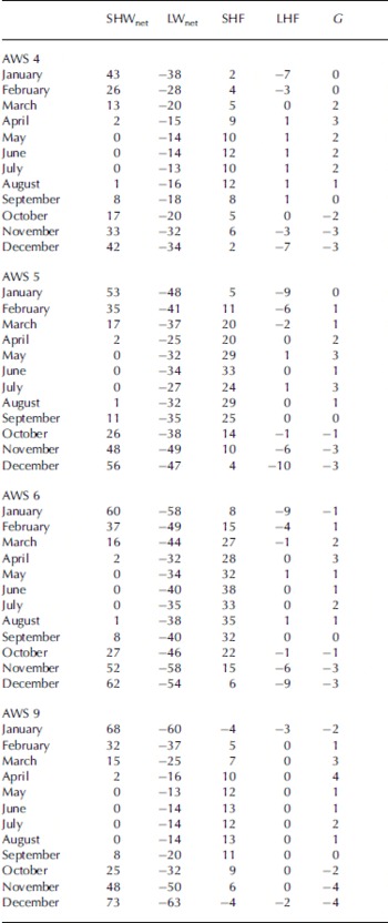
Annual mean values of the SEB components are listed in Table 2 (lower part), and the seasonal cycle (based on monthly means) is presented in Figure 6. For easy reference, the monthly means have also been listed separately in Table 3. To highlight SEB gradients along the AWS sites, Figure 7 shows coast-to-interior profiles of the SEB components averaged for conditions representative for midsummer (December–January) and mid-winter (June–July). From Table 2 it is clear that the annual mean SEB mainly reflects winter conditions, when R net and SHF approximately balance. Assuming SHF vanishes at the top of the atmospheric boundary layer, this implies quasi-continuous cooling of the lower Antarctic atmosphere. Figure 6 shows that this cooling is much more effective in the katabatic wind zone (AWSs 5 and 6) than elsewhere, peaking in winter with remarkably large monthly mean SHF values of 20–40Wm–2 (Figs 6b and c and 7c). This can be ascribed to the strong positive feedback between surface cooling and near-surface wind speed in the katabatic wind zone. Note the similarity between the seasonal cycles of wind speed and SHF (Figs 5 and 6), stressing the importance of wind-shear-generated turbulence in the stable Antarctic surface layer. At AWSs 4 and 9, where katabatic forcing is weak or absent, strong wind events are associated with synoptic activity and overcast conditions. Under overcast conditions, R net is close to zero so that the surface layer thermal stratification is near-neutral, and turbulent heat exchange small, in spite of the strong wind. Consequently, wintertime SHF at AWSs 4 and 9 is only 9–12Wm–2 (Fig. 7c).
Average seasonal cycle, 1998–2001, based on monthly means, of SEB components for (a) AWS 4, (b) AWS 5, (c) AWS 6 and (d) AWS 9.
Horizontal profiles along the AWS of seasonally averaged SEB components for the period 1998–2001. Summer is average of December and January; winter is average of June and July. (a) Summer radiation budget; (b) summer energy budget; and (c) winter energy budget.
Monthly mean energy-balance components (1998–2001) (units are Wm–2)
The magnitude of monthly mean G does not exceed 4Wm–2, with a maximum around April and a minimum around December at all AWSs (Figs 6 and 7), these being the months with the strongest temperature gradients in the near-surface snowpack. However small, the contribution of G to the SEB cannot be neglected; at AWS 9 in April, for instance, G contributes 30% of the energy transport towards the surface and removes 50% of the energy from the surface in November and December. Similar values apply to AWS 4. Deposition of moisture is a small source of heat during winter at all AWSs. Only at AWS 4 does it exceed 1Wm–2 during winter, comprising <10% of the heat transport towards the surface.
The SEB is very different during the brief summer, when a significant amount of shortwave radiation is absorbed at the snow surface. At the same time, LWnet becomes more strongly negative in response to a sharp increase in surface temperature (cf. Fig. 7a and c). As a result, R net becomes only slightly positive in December and January (Figs 6 and 7), with values between 4Wm–2 (AWS 6) and 9Wm–2 (AWS 9), where clouds are least frequent and optically thin. There is an abrupt transition from stable to unstable conditions between AWSs 6 and 9 (Fig. 7b). A negative monthly mean SHF implies that daytime cooling of the surface by convection is larger than nighttime heating of the surface by a downward-directed sensible heat transport. The explanation for the relatively strong convection on the plateau is two-fold: first, nocturnal slope flows in the katabatic wind zone generate large positive SHF that keeps the daily and monthly mean SHF positive. Second, the most important daytime heat sink at the lower sites is sublimation, with summertime mean values of –7 to –10Wm–2 (Fig. 7b). On the plateau, however, low temperatures limit sublimation (Fig. 5d); in the absence of other significant heat sinks, surface temperatures can rise rapidly in daytime causing significant convection. The daily development of a shallow (≈100 m) but well-defined daytime mixed layer on the Antarctic Plateau has been confirmed by SODAR (sonic detection and ranging) measurements at Dome C (Reference Mastrantonio, Malvestuto, Argentini, Georgiadis and ViolaMastrantonio and others, 1999) and tethered balloon soundings at Kohnen base (Reference Van As, van den Broeke and van de WalVan As and others, 2005).
At AWSs 4–6, the contribution of melt becomes non-zero in December and January, but it remains a relatively small component of the SEB (Figs 6 and 7). For the summer mass balance, however, melting constitutes a significant negative contribution at AWSs 4 and 5 (Reference Van den Broeke, Reijmer and van de WalVan den Broeke and others, 2005).
4. Conclusions
We calculated the seasonal cycle of the Antarctic SEB using 4 years of extensively quality-controlled AWS data. The four AWSs used in this study are situated on the coastal ice shelf, in the coastal and inland katabatic wind zone and in the interior plateau of Dronning Maud Land. Calculated and observed 2 hourly mean surface temperatures have a RMSD <2 K for the plateau AWS (corresponding to an uncertainty in the SEB of 5Wm–2) and <1 K (3Wm–2) for the other AWSs.
At all AWSs the annual mean net radiation is negative, resulting in a stably stratified surface layer. This requires wind shear to generate turbulent heat exchange, so that differences in the seasonal cycle of the SEB can be explained largely in terms of differences in wind climate. In the katabatic wind zone, the combination of clear skies and strong winds generates a large downward turbulent flux of sensible heat, which is especially large (20–40Wm–2) in winter. On the coastal ice shelf and the interior plateau, episodes with strong winds are associated with overcast conditions, limiting sensible heat transport to around 10Wm–2.
During the short Antarctic summer (December and January), net radiation becomes slightly positive. At the low-elevation AWSs, sublimation of snow from the surface is the main compensating heat loss. On the high plateau, even in summer, temperatures are too low for significant sublimation to occur; as a result, surface temperatures rise quickly in daytime, causing convection to be the main surface heat sink in the Antarctic interior.
Acknowledgements
We thank C. Genthon, G. Krinner, J. Box and A. Monaghan for carefully reviewing the manuscript. Numerous colleagues at Institute for Marine and Atmospheric Research Utrecht and abroad are thanked for AWS support. This work is partly funded by the Netherlands Antarctic Programme (NAAP) and the Netherlands Organization of Scientific Research, Earth and Life Sciences section (NWO/ALW). This work is a contribution to the ‘European Project for Ice Coring in Antarctica’ (EPICA), a joint European Science Foundation (ESF)/European Commission (EC) scientific programme, funded by the EC and by national contributions from Belgium, Denmark, France, Germany, Italy, the Netherlands, Norway, Sweden, Switzerland and the United Kingdom. This is EPICA publication No. 110.


