

1 Introduction
Intense ultra-short pulse lasers, in the range of hundreds of terawatts (TW) to the petawatt (PW) level, are unique tools for a wide range of experiments contributing to the advancement of many scientific research areas, such as laboratory astrophysics[Reference Remington, Arnett, Drake and Takabe1], high-energy-density physics[Reference Roth, Cowan, Key, Hatchett, Brown, Fountain, Johnson, Pennington, Snavely, Wilks, Yasuike, Ruhl, Pegoraro, Bulanov, Campbell, Perry and Powell2], particle acceleration schemes[Reference Bartal, Foord, Bellei, Key, Flippo, Gaillard, Offermann, Patel, Jarrott, Higginson, Roth, Otten, Kraus, Stephens, McLean, Giraldez, Wei, Gautier and Beg3, Reference Ledingham and Galster4] and others.
Moreover, the secondary radiation sources that they produce are now being proposed as facilities themselves.
To overcome the limitations of the existing high-peak-power systems in delivering the next generation of state-of-the-art lasers, the combination of the technology developed for sub-30 fs Ti:sapphire laser systems with the energies provided by nanosecond laser systems (energies of hundreds of Joules as Nd:glass or novel diode-pumped solid-state laser (DPSSL) systems) is essential.
To reach this goal, we have designed a laser system fully based on the optical parametric chirped pulse amplification (OPCPA) where the last two amplification stages are pumped by two Nd:glass laser systems.
The OPCPA technique[Reference Ross, Matousek, Towrie, Langley and Collier5–Reference Dubietis, Jonušauskas and Piskarskas9] has several important advantages with respect to classical chirped pulse amplification (CPA)[Reference Strickland and Mourou10], originally developed for ultra-short pulse amplification with laser amplifiers (based on population inversion in a laser gain medium). It allows the bandwidth to be extended to more than 100 nm without the limitation of gain narrowing. The bandwidth is determined by the phase matching and the transparency of the nonlinear crystals and not by the gain bandwidth of materials.
The single-pass parametric gain in a nonlinear crystal can be as high as 7 × 10⁷[Reference Musgrave, Shaikh, Galimberti, Boyle, Hernandez-Gomez, Lancaster and Heathcote11], so OPCPA systems require fewer amplification stages (and, hence, smaller B-integrals), allowing simpler and more compact setups with respect to CPA systems.
In OPCPA systems, the contrast is generally highly improved. Unlike the fluorescence in CPA gain media, the parametric fluorescence of the OPCPA only occurs during the temporal duration of the pulse. In general, adopting initial amplification stages with a pump duration of a few picoseconds, the contrast is highly improved outside this time window.
Finally, thermal effects such as thermal aberrations[Reference Hernandez-Gomez, Collier, Hawkes, Danson, Edwards, Pepler, Ross and Winstone12, Reference Ahmad, Galletti, Oliveira, Dilworth, Robinson, Galimberti, Crawford, Musgrave and Esser13] and thermal lensing, relevant in high-average-power pulse generation, are much weaker when compared with a laser gain medium because of the instantaneous nature of the process. The lack of significant thermal heating improves the beam quality of the amplified pulses and it allows scaling to high energy and high peak power levels. The OPCPA system average power and repetition rate are just determined by the implemented pump lasers.
On the other hand, the OPCPA concept presents some disadvantages/setup difficulties with respect to the classical CPA with laser amplifiers such as the pump/signal temporal matching and synchronization to optimize the gain, the required pump spatial uniformity to obtain uniform spatial gain, and the limited number of nonlinear crystals (as lithium triborate (LBO) crystals, potassium dideuterium phosphate crystals and their isomorphs (KDP, KD*P), and yttrium calcium oxyborate crystals (YCOB) crystals) with a sufficiently large aperture for high-energy stages.
The Vulcan OPCPA PEtawatt Laser (Vulcan OPPEL) system, an all-OPCPA auxiliary PW beamline project for pump-probe and betatron imaging experiments in VULCAN (CLF, RAL), is shown in Figure 1. It is designed to deliver 30 fs, 30 J pulses centered at 870 nm with a 5 min repetition rate. The interaction chamber making use of this beamline can also use a Nd:glass-based PW laser (which is short-pulse PW, 500 J, 500 fs) and a 250 J, ns laser capability. Furthermore, it is anticipated that in the future the existing short-pulse PW beamline could be converted into a kJ ns regime beamline if required for an experimental campaign. The main design of the target area will aim at creating a stable betatron radiation beam to be used as a probe for the main experimental campaign pursued with the VULCAN laser. Meanwhile, the ability to perform experiments with high intensity, using just the new beamline, is retained.
Sketch of the Vulcan OPPEL laser system.

In this communication, we present a system based on LBO[Reference Nikogosian14].
Section 2 provides an extensive discussion for this choice as the amplification material.
In summary, the 30 J specification requires a crystal that supports a 100 mm × 100 mm working aperture. LBO[Reference Zhu, Xie, Sun, Kang, Yang, Guo, Zhu, Zhu, Gao, Liang, Cui, Yang, Zhang and Lin15] is the crystal with the highest nonlinearity that can be grown to such a size. For higher-energy schemes, KD*P is a more common choice[Reference Lozhkarev, Freidman, Ginzburg, Katin, Khazanov, Kirsanov, Luchinin, Malshakov, Martyanov, Palashov, Poteomkin, Sergeev, Shaykin, Yakovlev, Garanin, Sukharev, Rukavishnikov, Charukhchev, Gerke and Yashin16–Reference Danson, Haefner, Bromage, Butcher, Chanteloup, Chowdhury, Galvanauskas, Gizzi, Hein, Hillier, Hopps, Kato, Khazanov, Kodama, Korn, Li, Li, Limpert, Ma, Nam, Neely, Papadopoulos, Penman, Qian, Rocca, Shaykin, Siders, Spindloe, Szatmári, Trines, Zhu, Zhu and Zuegel19].
We discuss the general system architecture in Section 2, and a theoretical study of the spectral bandwidth obtainable with the Vulcan OPPEL system is presented as well. In Section 3, the commissioned picosecond front end is described in detail. It is optimized and automated to ensure operational fitness. On its own, it is a stable laser system delivering 1.5 mJ, centered at 870 nm with 180 nm bandwidth that has been compressed to sub-15 fs using a compact four-pass single-grating compressor; subsequently, implementing the spectral shaping stage, it can be compressed down to ~13 fs.
Finally, in Sections 4–6, we present the high-energy amplification stages, ultra-broadband beam transport, and the final high-energy compressor, respectively.
2 Vulcan OPPEL architecture
The general architecture of the Vulcan OPPEL system is given in Figure 1. It consists of three main blocks:
• the front end composed of the picosecond front end (Ultra-broadband mJ-level ps front end in Figure 1) and the nanosecond front end (Ultra-broadband J-level ns front end in Figure 1) able to deliver 1 J (at least), 3 ns stretched pulses at 2 Hz repetition rate;
• the high-energy amplification stage (Ultra-broadband high-energy amplification stages in Figure 1) composed of two large OPCPA stages able to deliver 50 J, 3 ns stretched pulses at 5 min repetition rate;
• the folded gold-coated grating compressor (Compressor in Figure 1) able to compress the 3 ns, 50 J pulses to <30 fs.
In further detail, regarding the front end, the picosecond stage is highly important to improve the contrast of a system, because the super-parametric fluorescence will only be created during the duration of the pump operation.
Regarding the high-energy amplification stage, owing to the lack of thermal effects in the parametric amplification itself, its repetition rate (and consequently of the Vulcan OPPEL system) is determined by the repetition rate of the VULCAN laser (pump system). At first, it will be one shot every 20 min, but later, with a newly designed cooled disk amplifier, the repetition rate will be increased to one shot every 5 min. In the high-energy amplification stage, the first OPCPA is pumped by a homemade 30 J laser system that is frequency-doubled to 15 J at 526.5 nm. Meanwhile, the second OPCPA is pumped by the second harmonic of one of the long pulse beamlines of the VULCAN laser facility (250 J, 3 ns), meaning the Vulcan OPPEL system has to be temporally synchronized with the VULCAN, allowing it to perform a wide range of experiments.
The 3 ns, 50 J amplified signal will be compressed in an off-plane folded compressor, reported in detail in Section 6. The output of the compression stage and, consequently, the Vulcan OPPEL beamline reaching the interaction chamber is 30 J, 30 fs with a 5 min repetition rate.
BBO, LBO, and KD*P were the three nonlinear crystals considered for implementation in the system design. We have evaluated the following characteristics: available aperture, damage threshold, spectral bandwidth, central wavelength, and nonlinear coefficient d eff.
A comparison between the nonlinear crystals is given in Table 1, where the central wavelength has been chosen for maximum bandwidth.
Comparison of the three evaluated nonlinear crystals to be implemented in the Vulcan OPPEL system at different central wavelengths.

BBO is the crystal with the central wavelength closest to the Ti:sapphire system and the nonlinearity (d eff) is the highest. It is, however, quite clear that the crystal size is not sufficient to sustain the required 50 J of energy per pulse in the high-energy amplification stage.
Although BBO could be used in the low-energy OPCPA stages, its spectral amplification range is only just able to handle the required spectral region, potentially putting at risk the 30 fs specification for the project (see Figure 2).
Simulated spectra at each stage of the system with LBO and the front end with BBO.

In addition, using the same crystal type throughout enables standardization of the crystals simplifying the management and procurement of spares for the operation of the facility. On the other hand, LBO crystals can be obtained with sufficient size and demonstrate better performance with respect to KD*P with regards to several criteria: smaller walk-off, damage threshold, and, more importantly, higher nonlinearity and broader supported bandwidth. The transmission range of LBO is similar to BBO, ranging from 160 to 2600 nm[Reference Smith26]; the lower d eff in LBO (in comparison with BBO) means that we will have to have around six times the length of crystal L c for the same pump intensity I p (according to the proportionality of the conversion efficiency ∝ I p × L c ×  ${d}_{\mathrm{eff}}^2$
).
${d}_{\mathrm{eff}}^2$
).
We could use thinner OPCPA crystals, but this would require an increased pump intensity. If this is achieved by reducing the pump duration, it would reduce the timing jitter tolerance between the pump and signal pulses. This could also reduce the lifetime of some of the optical components, reducing the reliability of the overall system.
A drawback of using longer crystals is the role played by the walk-off; however, maintaining a low fluence on the crystal, with a larger beam, permits us to minimize the importance of walk-off and to maintain high efficiency. Running the system at lower fluence also increases its robustness and decreases deterioration of the optics and crystals.
In detail, the walk-off length is defined by
 $$\begin{align*}{L}_{w_{\mathrm{p}}}=2{w}_{\mathrm{p}}/\tan \rho, \end{align*}$$
where, for our picosecond front end, w p ~ 1.5 mm is pump waist and ρ ~ 7.7 mrad is the walk-off angle, so the interaction length is of the order of tens of centimeters. In our noncollinear situation with an internal angle (pump signal) ~ 1.4°, the walk-off effect was minimized by observing the maximum of the parametric fluorescence cone[Reference Stanislauskas, Balčiūnas, Tamuliene, Budriūnas and Varanavičius27].
Another promising crystal for large OPCPA is YCOB because of the supported bandwidth and the high nonlinearity[Reference Galletti, Pires, Hariton, Alves, Oliveira, Galimberti and Figueira28, Reference Pires, Galimberti and Figueira29]. However, the commercial availability of this crystal was assessed in the planning phase of the project and it was judged to be not mature enough for the purpose of the project.
A simulation code[Reference Galimberti, Hernandez-Gomez, Musgrave, Ross and Winstone21, Reference Galletti, Pires, Hariton, Alves, Oliveira, Galimberti and Figueira28, Reference Pires, Galimberti and Figueira29] was developed to study the system performance and bandwidth of the noncollinear OPA (NOPA) stages based on LBO crystals of the PW system. The code can consider the phase matching conditions and the saturation effect. The simulations show the supported spectrum at the output of the picosecond front end, nanosecond front end, and before the compressor stage as in Figure 3.
Simulated spectra at each stage of the system compared with the expected efficiency of the compressor.
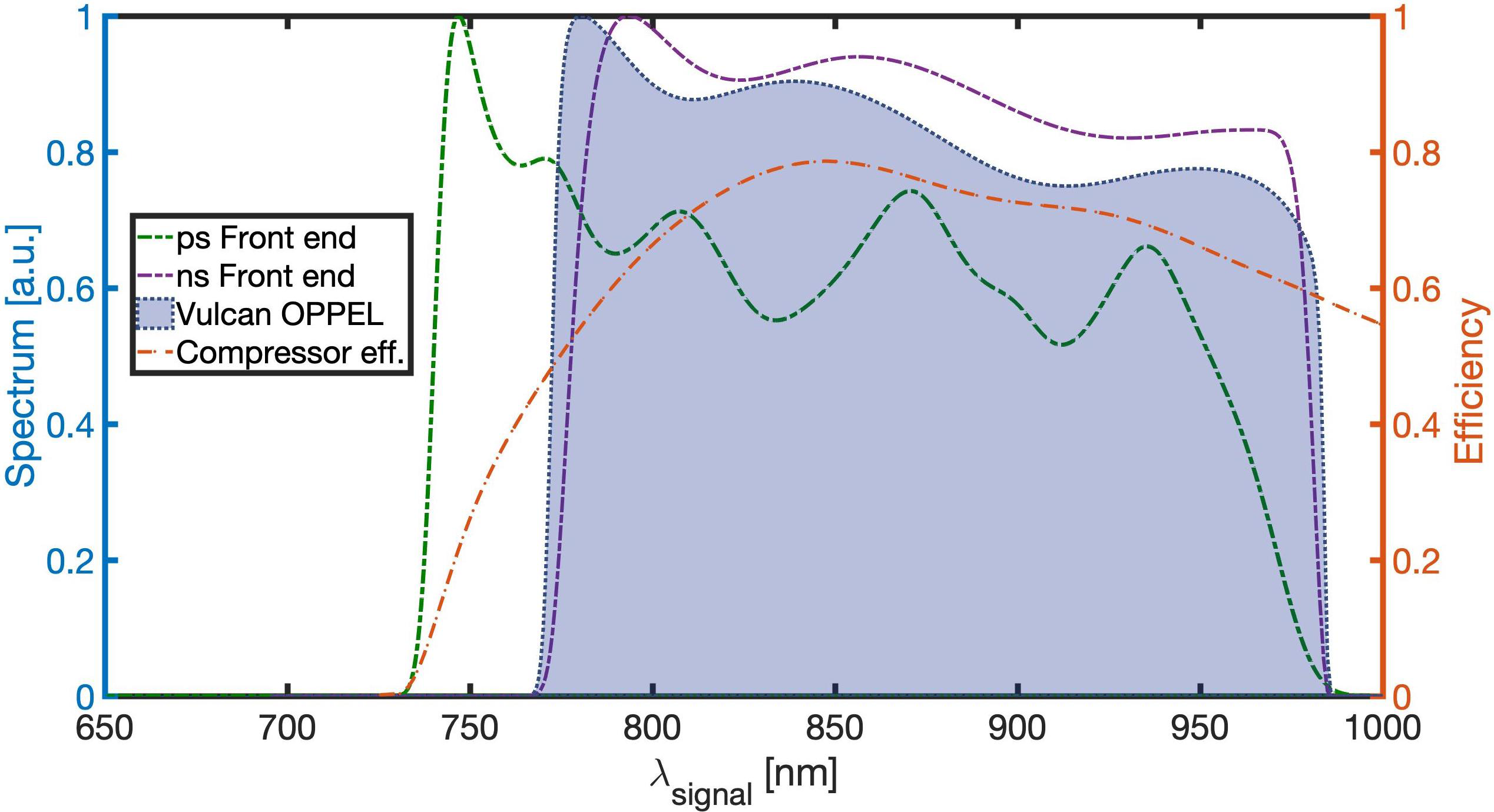
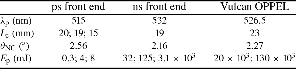
The pump wavelengths in our system are not exactly the same, owing to the different laser technologies in use for the pump lasers as summarized in Table 2. The first four stages are pumped at 515 nm, the following three are pumped at 532 nm, and the last two high-power stages are pumped at 526.5 nm.
Summary of the simulation parameters regarding the NOPA block stages.
The simulated input spectrum is similar to the broadband Ti:sapphire oscillator that has spectral intensity modulations as shown in Figure 4.
Measured spectrum of the Ti:sapphire system showing intensity modulation.

The saturation of the nanosecond stages reduces these modulations and amplifies the longer wavelengths with respect to the shorter ones.
Within the bandwidth of the amplifiers, the overall obtainable bandwidth is also related to the spectral efficiency of the gratings implemented in the compressor. The current reliable technology is based on gold-coated gratings that require operation with p-polarized beams to obtain >90% efficiency over the supported bandwidth.
The expected efficiency for the compressor grating, supplied by the manufacturer, allowed us to estimate the compressor efficiency as shown in Figure 3.
To guarantee a good compressor efficiency and to avoid over-constraining the system, we assessed the operating wavelength range between 800 and 960 nm (full width at half maximum (FWHM)), allowing some margin on the amplification bandwidth.
3 Front end
The front end consists of seven noncollinear OPA stages:
• four of them constitute the picosecond front end pumped by ~0.3 mJ (NOPA1 and NOPA2) and ~4 mJ/8 mJ (NOPA3/NOPA4); and
• the following three NOPAs of the nanosecond front end are pumped by 4.5 J (with a shapeable temporal profile).
The spectral phase in the system is controlled by a mix between dispersive material and dispersion gratings, with two active spectral phase control systems that are two acoustooptic tunable filters (Dazzlers[30]).
The first stretcher consists of two double-pass 25 mm thick BK7 blocks both set at Brewster’s angle (group velocity dispersion (GVD) ~38.33 fs2/mm, third-order dispersion (TOD) ~34.84 fs3/mm at 870 nm), as shown in Figure 5 (Stretcher). The estimated stretched signal pulse duration is 3 ps (FWHM).
Sketch of the picosecond mJ-level front end experimental setup. The commercial Ti:sapphire oscillator (Venteon) and the two commercial RGAs (S-pulse and Magma25) are seeding and pumping the four NOPA stages, respectively. The compact seed stretcher is made by two BK7 glass blocks, as shown below the Venteon box. The violet dashed boxes are hybrid achromatic telescopes (ACTs, described in Section 5) with a 2× magnification ending with an off-axis parabola (OAP), and the orange dashed boxes between NOPA2 and NOPA3 show achromatic-lens telescopes (three-lens systems) for the propagating broadband signal; meanwhile, the vacuum spatial filters (VSFs) in the light blue dashed boxes show the under-vacuum telescopes (two-lens systems) for the Magma25 RGA. Note: 4-pass MC, 4-pass Martinez compressor; D, Dazzler, spectral shaping and stretching stage; SHG, second-harmonic generation stages.

After the first two picosecond stages, the amplified signal is further stretched both in the LBO crystals and in the Dazzler itself, which is constituted by a 50 mm TiO2 crystal[Reference Tournois31], and the pulse is estimated to be 8 ps in the third and fourth stages. The Dazzler can actively self-compensate, but this reduces its ability to actively change the phase; because of this, we decided to include its contribution to the dispersion in the system design.
Before entering the last amplification stages of the front end, the J-level nanosecond stages, the signal is stretched to 3 ns with a grating stretcher with a chirp rate of 18.75 ps/nm. The pulse duration is then approximately constant until it is compressed in the final nanosecond compressor, as mentioned previously.
3.1 Picosecond front end
The system is pumped by two mJ-level regenerative amplifiers (RGAs) and generates pulses up to 1.5 mJ with a central wavelength of 870 nm (~180 nm) at 100 Hz repetition rate.
The system demonstrates good power and temporal stability. The OPCPA system is seeded by a commercial ultrabroadband 80 MHz Ti:sapphire oscillator (Venteon, Laser Quantum[32]), which delivers nJ-level, sub-6 fs pulses. The broadband pulse delivered by the Venteon oscillator is stretched in a double-pass BK7 glass stretcher.
The estimated stretched signal pulse duration is 3 ps (FWHM). The implemented configuration uses pump pulses of 10 ps (the first two stages) and 20 ps (the last two stages) while keeping the signal pulses stretched to 3 or 8 ps, respectively, which greatly improves the ns contrast[Reference Musgrave, Shaikh, Galimberti, Boyle, Hernandez-Gomez, Lancaster and Heathcote11, Reference Moses, Manzoni, Huang, Cerullo and Kärtner33]. The pump is a factor of between two and three times longer than the signal in order for the system to be less sensitive to timing jitter, this is also needed to amplify the entire spectrum because the pulses are not temporally top hat.
The synchronization between the pump and the signal is performed by temporally locking (electronically synchronizing) the fiber oscillator to the main laser oscillator, with a jitter of the order of 100 fs[34].
The overall efficiency of the system (pump signal) is 12% while the last stage presents ~18% conversion efficiency.
3.1.1 Picosecond NOPCPA pumping system
A fiber laser, delivering nJ-level, 200 fs, 40 mW, and 40 MHz repetition rate, is split equally and used to seed the two regenerative Yb-doped amplifiers, after being stretched with fibers to the ps regime.
The S-pulse Yb-based RGA delivers 1.2 mJ pulses to the second-harmonic generation (SHG) crystal, with 16 ps temporal length (FWHM) centered at 1030 nm at 100 Hz repetition rate, and is the pump system of the first two NOPA stages. The output of the S-pulse amplifier was frequency-doubled with ~50% efficiency in a 2.5 mm long BBO crystal with about 6 GW/cm2 intensity. The infrared (IR) beam was measured and a Gaussian beam profile was observed at the crystal input surface, while the SHG beam was measured after the doubling crystal (~5 cm) as shown in Figure 6.
Spatial profile of (top) the S-pulse output on the SHG crystal and (bottom) the SHG pump.

After the doubling stage, the pulse duration is about 10 ps (FWHM) with a measured bandwidth of 1.7 nm (FWHM). Both the temporal profile and bandwidth (Figure 7, bottom) were benchmarked by performing simulations of the SHG stage. BBO was chosen as the doubling crystal after performing an extensive study of SHG crystals such as LBO and BiBO. The nonlinear crystal parameters were chosen according to numerical simulations, solving the three-wave mixing equation in the SHG regime, comparing the efficiency and stability as different S-pulse energy fluctuations (Figure 7, top), and supported bandwidth (Figure 7, bottom). Subsequently, the frequency-doubled pump beam is split equally for the two-NOPA stages. This choice was taken for the low-energy picosecond stages, maintaining an intensity of <5 GW/cm2 (operational system) with a 20 mm LBO on both stages, so that all the available bandwidth can be optimally amplified. The pump beam diameter (FWHM) was set to 1.3 mm for both stages to keep the fluence at about 0.03 J/cm2 on the NOPA crystals. The low fluence is designed to increase the robustness of the system and to decrease the deterioration of optics.
(Top) BBO efficiency (η) and stability considering initial intensity variation in the ±5% range. (Bottom) SHG spectrum (S 2ω) with BBO as a nonlinear crystal.

The Magma25 Yb-based RGA delivers to the SHG crystal 23 mJ pulses, with 26 ps temporal length (FWHM) centered at 1030 nm at 100 Hz repetition rate, and it is employed as the pump system of the last two NOPA stages.
The Magma25 amplifier’s output was frequency-doubled with ~61% efficiency in a 2 mm long BBO crystal with about 6 GW/cm2 intensity. The IR beam was measured and a Gaussian beam profile was observed at the crystal input surface, whereas the SHG beam was measured after the doubling crystal (~5 cm) as shown in Figure 8.
Spatial profile of (top) the Magma25 output on the SHG crystal and (bottom) the SHG pump.

After the doubling stage, the pulse duration is about 19 ps (FWHM). The temporal profile was benchmarked by performing simulations of the SHG stage, as in the previous paragraph. Subsequently, the frequency-doubled pump beam is not equally split between the two NOPA stages, and the ratio is 1:2. This choice was made to maintain an intensity of <5 GW/cm2 in 8 and 20 mm LBO crystals; all the available bandwidth can be optimally amplified. The pump beam diameter (FWHM) was set to 5 and 8 mm for the stages to keep the fluence at about 0.03 J/cm2 on the OPA crystals. In addition, in this stage, the low fluence is designed to increase the robustness of the system and to decrease the deterioration of optics.
3.1.2 μJ-level NOPA stages
The amplification efficiency and the signal quality are optimized, setting the seed pulse duration shorter than the pump (ratiop,s ~2). The signal diameters are also fixed for the two NOPA stages; the seed diameter is 2.5 mm (FWHM). The two single-pass NOPA stages, shown in Figure 5, are almost identical and based on 7 mm × 7 mm × 20 mm (NOPA1) and 7 mm × 7 mm × 19 mm (NOPA2) LBO crystals cut at 12.9° angle in the xy-plane and their temperature is stabilized by an oven to improve long-term stability. Both are noncollinear Type-I phase-matched at 870 nm (2.56° pump-signal external angle) for broadband amplification of the fundamental Ti:sapphire oscillator seed spectrum.
The beam optical layout, after the first amplification stage, was realized by implementing a double mirror beam transport line injecting the signal into an in-house-developed achromatic telescope (ACT; dashed pink box in Figure 5), as described in Section 5.
The broadband parametric amplification stages are based on a traditional single-pass noncollinear geometry. In the first NOPA stage, a high single-pass gain (~nJ → ~100 nJ) was achieved at a pump intensity of ~3 GW/cm2.
Meanwhile, the second amplification stage maintaining the same pump intensity on the crystal works in a saturated regime. As reported in Table 3, its output has an energy up to 30 ҼJ before compression while maintaining an ultrabroadband spectrum.
Summary of the ҼJ-level NOPA stages.

In Figure 9, both the nJ-level signal spectrum (SEED, blue area) and the amplified bandwidth ~160 nm (NOPA2, orange line) are shown. The temporal length of the amplified signal is about 3 ps.
Spectra related to the signal and the NOPA2 stage.

The synchronization between pump and signal pulses has been optimized by maximizing the NOPA output power and broadband spectrum simultaneously (NOPA1 stage is more sensitive to temporal jitter because it is not in the saturated regime). The optimization can be realized manually or can be controlled with an in-house-developed feedback loop relying on the detected OPA signal for various delays (active stabilization of pump–seed delay). The ‘pump to signal’ efficiency of the second NOPA is 10%, leading to an 8% overall system efficiency. The output spatial profile for both NOPA stages is Gaussian, as shown in Figure 10. Stability measurements were performed on the NOPA2 pulses power (see Figure 11) for over 50 min without active stabilization of the temporal ‘signal–pump’ delay for both amplification stages.
Near-field spatial profile of the output of (top) the first and (bottom) the second amplification stages.

Stability measurements performed on the NOPA2 pulses power reveal that the system is autonomously stable for about 22 min with RMS values of 3.7%. The NOPA1 PD signal value is increased by a factor of 0.3V to be better represented in the figure.

The root-mean-squared (RMS) error values of 3.7% were retrieved for the power of NOPA2. Power drifts were observed on longer timescales, which could be corrected by minor adjustment of the delay between signal and pump.
In the present work, the super-fluorescence[Reference Stuart, Bigourd, Hill, Robinson, Mecseki, Patankar, New and Smith35] was evaluated. Owing to the design of the stages, the pump spatial extension is smaller than the seed one (soft aperture) ensuring that the pump energy is employed for the amplification process instead of generating super-fluorescence.
If the signal in front of the first NOPA stage is blocked, the single-pass stage generates insignificant super-fluorescence background. The ratio between the NOPA2 integrated spectrum and the super-fluorescence spectrum gives us an estimate of the super-fluorescence that is less than 1 ҼJ. The amount of super-fluorescence is expected to be lower in the seeded than in the unseeded case.
Finally, the NOPA2 output energy is around 30 ҼJ. The output of NOPA2 is sent to the Dazzler (Fastlite[30]) and, subsequently, the diffracted beam is amplified in the next two stages. It is adopted for dispersion control to compensate for the high-order spectral phase and as a broadband pulse stretcher (10 ps/~180 nm) is implemented. The Dazzler transmission is about 10%, and thus the seed for the third stage is about 3 ҼJ.
3.1.3 mJ-level NOPA stages
The ratiop,s is maintained at ~2. Having higher pumping energy and an unequal splitting in these stages with respect to the previous two, the signal size is increased and different for the two stages. An ACT (4× magnification) is installed between the Dazzler and NOPA3. The signal diameters are 6 and 10 mm (FWHM) with the pump being smaller than the signal with diameters of 5 and 8 mm, respectively.
The two single-pass NOPA stages, shown in Figure 5, are almost identical and based on 15 mm × 15 mm × 15 mm (NOPA3) and 20 mm × 20 mm × 20 mm (NOPA4) thermally stabilized LBO crystals cut at 12.9° angle in the xy-plane, both noncollinear Type I phase-matched at 870 nm (2.56° pump-signal external angle) for broadband amplification.
The optical layout is identical in the first two NOPA stages as shown in Figure 5 (ACT dashed box), as described in Section 5. The two final stages are also based on a traditional single-pass noncollinear geometry for broadband parametric amplification.
The signal size is increased by a factor of four by an ACT (shown in Figure 5) owing to the increased pump energy. At the same time, owing to the presence of highly dispersive material, the signal is stretched in the spectral shaping stage. The signal temporal length is about 10 ps.
In the third NOPA stage, a single-pass gain of 100 (~3 ҼJ → ~300 ҼJ) was achieved at a pump intensity of ~3 GW/cm2. The fourth amplification stage pump is twice the energy of the third stage, but with the same pump intensity on the crystal of about 3 GW/cm2. The output of the second amplification stage has an energy up to 1.5 mJ, as reported in Table 4, before compression while maintaining a broadband spectrum (~180 nm).
Summary of the mJ-level NOPA stages.

In Figure 12, both the mJ-level signal spectrum (NOPA4, blue continuous line) and the SPIDER retrieved bandwidth ~180 nm (NOPA4, violet dashed line) are shown. The temporal length of the amplified signal is around 10 ps.
Spectra related to the NOPA4 stage.

The synchronization between pump and signal pulses has been optimized by maximizing the NOPA output power and broadband spectrum simultaneously. As in the first double stage, the synchronized optimization can be realized manually or by feedback loop relying on the detected NOPA signal for various delays.
The ‘pump-to-signal’ NOPA4 efficiency is 19%, leading to a 12.5% overall system efficiency. The output spatial profile for both NOPA stages is shown in Figure 13. Stability measurements were performed on the NOPA4 pulse power (see Figure 14) for almost 1 h without active stabilization of the temporal ‘signal–pump’ delay for both amplification stages. The RMS error values of around 4% were retrieved for NOPA4 power. Power drifts were observed on longer timescales, owing to the temporal jitter influencing the first two NOPA stages, which could be corrected by minor adjustment of the delay between signal and pump.
Near-field spatial profile of the output of (top) the third and (bottom) the fourth amplification stages.

Stability measurements performed on the NOPA4 pulses power reveal that the system is autonomously stable for about 1 h with an RMS value of around 4%. After 1 h, a drift is noticeable and the RMS value is degraded to 10%.

The temporal lengths of the interacting beams in stages NOPA3 and NOPA4 are twice that of stages 1 and 2 so the temporal jitter (~0.5–1 ps) has less effect. In the present work, the super-fluorescence[Reference Stuart, Bigourd, Hill, Robinson, Mecseki, Patankar, New and Smith35] was evaluated. The design of stages NOPA3 and NOPA4 mimics that of stages NOPA1 and NOPA2 with the pump beams being smaller than the signal beams to act as soft apertures. This ensures that the pump energy is employed for the amplification process instead of generating super-fluorescence.
If the signal entering the NOPA4 stage is blocked, the single-pass stage generates an insignificant super-fluorescence background of the order of 0.05 mJ. The amount of super-fluorescence is expected to be lower in the seeded than in the unseeded case.
3.1.4 Stability of the mJ-level compressed front end
To test the stability and compressibility of this system we designed a simple test compressor.
Up to this point in the system, both the pump and seed pulses have experienced material dispersion. The stretching is essential owing to timing jitter sensitivity and to assure a good overlap between the entire seed spectrum and the most intense part of the pump.
The seed stretching was performed using a bulk stretcher, as in Figure 5, for the first two stages. It was chosen to minimize the loss before the NOPA1 stage to maximize seed energy input and to avoid unnecessary parametric super-fluorescence in the ps range.
An extensive study of various stretcher configurations was performed, including simulations of their performances. A grating stretcher would require a few millimeters between gratings, which would be unpractical and lossy; meanwhile, a prism stretcher would require several meters between prisms and this would make the system alignment sensitive; and chirped mirrors with about 20 bounces on each one would have caused high-frequency variations in the phase, which would be difficult to compensate for. We decided to implement two double-pass blocks of glass at the Brewster angle (25.4 mm each). This configuration (bulk doublet) will enable us to eliminate the horizontal near-field offset that would exist because of a single block and because they are double-passed at a different height and co-planar, angular dispersion is compensated for.
Subsequently, after NOPA2, an acoustic–optical spectral shaping device is placed permitting high-order spectral phase compensation and simultaneously leading to a temporal stretching from 3 ps to approximately 10 ps.
Our spectrum, covering 180 nm (1/e 2 maximum) in the spectral domain, supports a Fourier limit temporal length ~12.8 fs, as in Figure 12. To perform the full compression, compensating for the induced stretch from the BK7 glasses, the Dazzler crystal, and the transmission material in the NOPCPA system, we used a compact four-pass single-grating Martinez compressor.
It is well known that a grating compressor exhibits a positive group delay dispersion (GDD) and a negative TOD (or vice versa), while bulk material in the near-IR has a positive GDD and a positive TOD. Owing to this, it is impossible to compensate for both the GDD and the TOD using a single-grating compressor, considering that we had previously used a bulk stretcher.
The designed setup is shown in Figure 15 and it can theoretically compress the pulse to sub-20 fs (highly sensitive to the grating separation).
Single-grating compressor stage sketch. Note: CM, corner mirror; M, mirror; GR, grating (line density = 1000 lines/mm, θ inc= 41°, θ out = 0°); L, achromatic lens (f = 15 cm), d GR–L ~15 cm and d GR–M2 ~35 cm.

The NOPCPA system output is extracted and injected directly into the compression stage. It consists of a compact four-pass single-grating Martinez compressor, as shown in Figure 15. The transmission of the grating compressor is 30%. Pulse characterization was performed with a SPIDER (Spider, APE[36]). The broadband spectrum supported by the SPIDER can measure the amplified spectrum by the NOPCPA stages, as shown in Figure 12. The measured spectrum of the SPIDER is about 180 nm and it would support 12.8 fs transform-limited pulses. We measure 15 fs pulses (1.17× transform limit pulses) with >90% of the energy in the central peak (see Figure 16(a)) with a good quality beam profile, leading to hundreds of GW-level peak power. In Figure 16(a), the SPIDER complete reconstruction is shown; pre-pulses and post-pulses are small but still noticeable meaning that there is residual third-order chirp. In this set of measurements, the Dazzler was just used as a stretching stage without the feedback loop to shape the spectral phase.
Profiles of compressed pulses measured with SPIDER diagnostics: (a) compressed NOPA4 temporal profile; (b), (c) stability measurement performed on the temporal length of the compressed NOPA4 output reveals that the system is autonomously stable for almost 60 min.
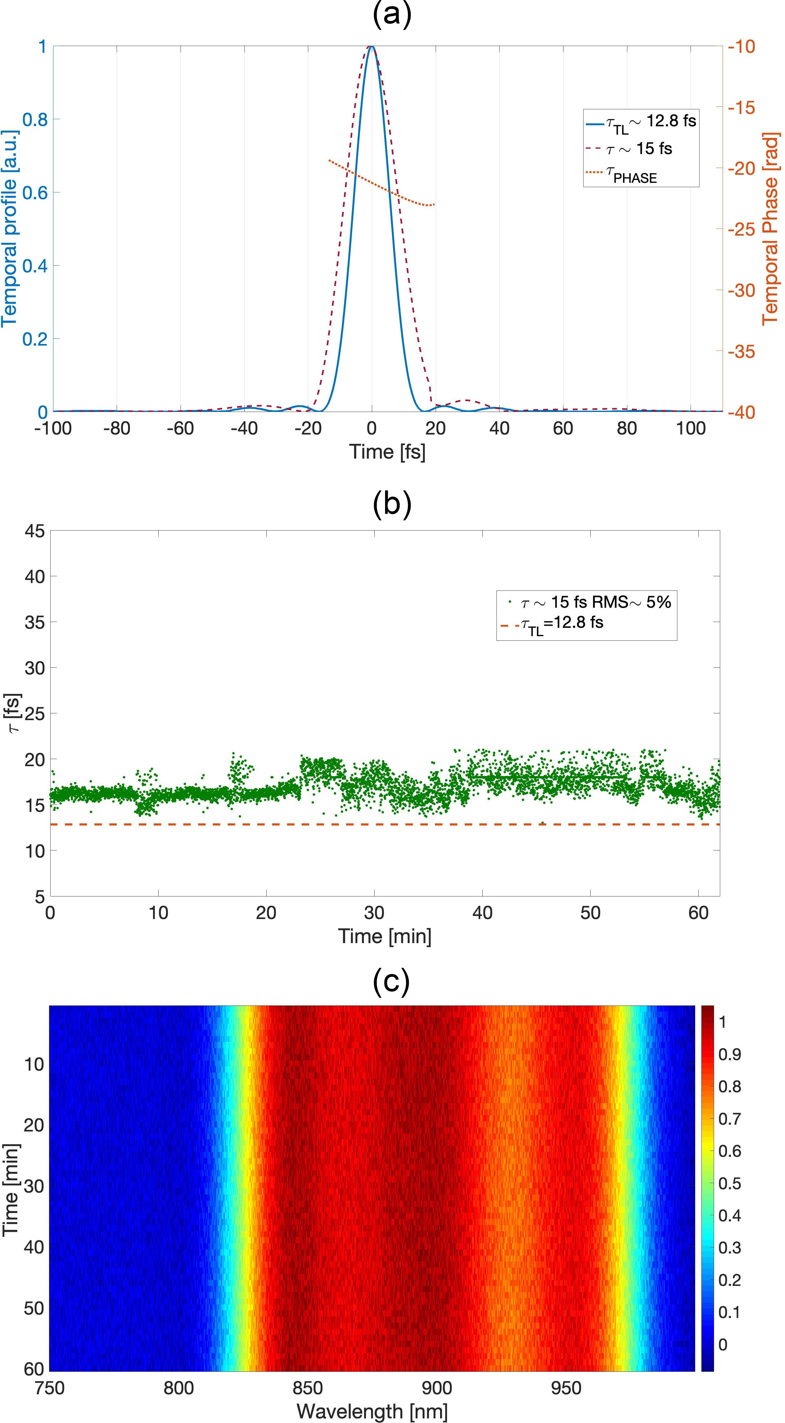
Stability measurements were performed on the temporal length of the compressed system (see Figure 16(b)). A stable output is noticeable through 60 min without active stabilization of the temporal ‘pump–signal’ delay for the amplification stages. An RMS error value of < 5% is shown for almost 1 h.
The sort of instability visible mostly in the second temporal region of the measurements is given by the satellite pulses because of their oscillating behavior. Owing to the highlighted motivation, a spectral shaping tool was implemented to successfully compensate for the higher-order spectral phase coefficients enabling us to fully compress the amplified pulses. The stability of the pulse duration confirms the spectral stability of the amplified signal after the fourth amplification stage (saturated regime), as shown in Figure 16(c).
3.2 Nanosecond amplification stages
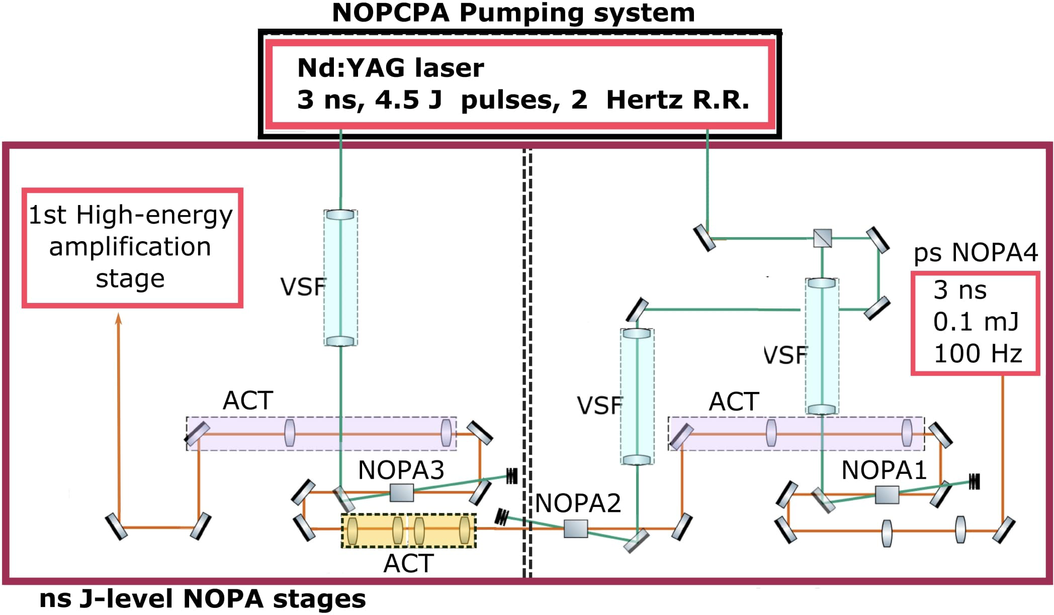
The nanosecond stretcher is a double-pass grating-based stretcher. Its transmission is estimated to be about 10%, and thus the seed for the ns front end is about ~0.1 mJ. Before injecting into the next amplification stage, we introduce another Dazzler: this is important to compensate for material dispersion. Next, pulses undergo further amplification in the ns front end pumped by a Nd:YAG laser delivering 3 ns, 4.5 J pulses with 2 Hz repetition rate. The first stage is aimed at recovering energy losses during stretching and spectral shaping. The pump laser is temporally shapeable and so it is possible to control the spectrum of the pulses[Reference Oliveira, Addis, Gay, Ertel, Galimberti and Musgrave37]. All stages have a fluence of approximately 2 J/cm2. The schematic for these stages is given in Figure 17.
Sketch of the nanosecond J-level front end experimental setup. The commercial Nd:YAG laser is pumping the three NOPA stages. The violet dashed boxes are hybrid ACTs (described in Section 5) with an OAP and the orange dashed boxes show under-vacuum achromatic-lens telescopes (three-lens systems) for the propagating broadband signal; the VSF light blue dashed boxes show the under-vacuum telescopes (two-lens systems).
The nanosecond front end, based on LBO crystal with 20 mm2 section and different thickness (as reported in Table 5), presents 20% efficiency and it delivers 1 J, 3 ns pulses at 2 Hz supporting a 200 nm bandwidth, shown in the simulation curve in Figure 3.
Summary of the J-level nanosecond NOPA stages.

All the nonlinear crystals in the J-level nanosecond NOPA stages are 5’ wedged[Reference Begishev, Bagnoud, Dorrer and Zuegel38] in the phase-matching critical direction to avoid post-pulses, which can be converted into pre-pulses. This will also decrease the amount of super-fluorescence created by the 3 ns pulses.
4 High-energy amplification stages
At this stage of the PW system, we needed to design and setup both the pump system and the high-energy amplification stages with the relative broadband beam transport.
The first high-energy stage is pumped by a 15 J green laser at 526.5 nm. A schematic of this system is shown in Figure 18[Reference Shaikh, Oliveira, Musgrave, Galimberti, Winstone and Hernandez-Gomez39].
Initially, it adopts a fiber electro-optic modulator (EOM) to shape the temporal profile of a continuous wave (CW) laser. The beam then goes through several amplifiers:
• first stage, a fiber amplifier with 13 dB gain;
• second stage, a home-built RGA, reaching up to 1 mJ;
• last stage, an amplification system based on Nd:glass with five amplifiers with growing apertures where the largest amplifier has 45 mm diameter (shown in Figure 18).
Design of a Nd:glass chain for the first high-energy pump. A 100 mW CW laser is sliced with a fiber EOM and successively amplified in a fiber to reach the nJ level. This is then amplified in an RGA to 1 mJ and injected into the chain. Note: F1, F2, Faraday; 9AMP, 16AMP, 25AMP, 45AMP, amplifiers with respective diameters in mm; SF, spatial filter; L, lens; PH, pinhole; VSF1, VSF2, vacuum spatial filters; RWP, rotating wave-plate to control output energy; λ/2, half-wave plate.

The laser delivers 30 J at 1053 nm. Finally, the output is converted to 526.5 nm in an LBO nonlinear crystal (50 mm × 50 mm) with an 80% conversion efficiency.
The first high-energy amplification stage, based on a 50 mm2 × 23 mm thick LBO crystal, with a 50% efficiency delivers 7 J, 3 ns pulses at 5 min repetition rate supporting a 200 nm bandwidth.
The second high-energy amplification stage pump is a VULCAN beamline (250 J and 3 ns). It is frequency-doubled in a KD*P 120 mm × 120 mm × 25 mm crystal with an expected net efficiency between pump IR and green available in the OPA crystal of ~50%. Consequently, the Vulcan OPPEL system will be automatically temporally synchronized with VULCAN. The second high-energy amplification stage, based on a 100 mm2 × 19 mm thick LBO crystal, with a ~40% efficiency delivers 50 J, 3 ns pulses at 20 min repetition rate supporting a 200 nm bandwidth, shown in the simulation curve in Figure 3.
The high-energy amplification NOPA stages parameters are summarized in Table 6.
Summary of the mJ-level NOPA stages.

As for the J-level NOPAs, all the nonlinear crystals in the high-energy NOPA stages are 5’ wedged[Reference Begishev, Bagnoud, Dorrer and Zuegel38] to avoid post-pulses and decrease the amount of super-fluorescence created by the 3 ns pulses.
An air-cooled Nd:glass amplifier is being tested, as shown in Figure 19, to increase the repetition rate to 5 min. This amplifier will have to be fired continuously to ensure thermal equilibrium.
Sketch of the upgraded air-cooled disk amplifier.

5 Ultra-broadband beam transport
Throughout the entire broadband PW system and especially between high-energy NOPA stages and the last amplification stage and the compressor, ACTs are set to transport all the amplified bandwidth and to maintain the established spatial signal–pump size ratio.
Three different options have been explored extensively and the implemented/designed layouts are as follows.
• Fully reflective: the telescope is composed of two curved mirrors, spherical or parabolic. This setup is perfectly achromatic, but it is more difficult to align. It also adds design complexity for the telescopes between the high-energy stages, where it is necessary to focus the beam under vacuum. It could also increase the complexity of the optical layout, owing to the off-axis geometry necessary on the curved mirrors.
• Achromatic lenses: custom-design air-spaced doublet or low dispersion lenses (such as CaF2 lenses) are able to support all the bandwidth and the telescope design is easy to implement and to maintain. The doublet could be also used as VSF windows to hold the vacuum, essential to avoid focusing in the air at high power. However, it could increase the B-integral and the availability of glasses in larger sizes could limit the possibility (and the cost) of the doublet. In addition, the ghost analysis could be complicated, owing to the larger number of surfaces.
• Hybrid lens and parabola: the telescope is composed of two lenses, one positive and one negative, and an OAP.
In the operational system, we have decided to use the telescope design with CaF2 lenses at low power and where it is possible to use a long focal lens, with f-number lower than f/40.
For shorter telescopes (f-number ~ f/20) and higher power, but still lens sizes of 50 mm, we are planning to use a custom-designed doublet.
In other cases, the hybrid design was designed, built, and implemented.
Let us consider a telescope composed of a positive plane convex lens defined by a refractive index n(λ) and a radius of curvature R. The focal length f p(λ) of this lens is
 $$\begin{align}{f}_{\mathrm{p}}\left(\lambda \right)=\frac{R}{n\left(\lambda \right)-1}\simeq {f}_0\left[1-\frac{n^{\prime}\left({\lambda}_0\right)}{n\left({\lambda}_0\right)-1}\left(\lambda -{\lambda}_{\mathrm{0}}\right)\right], \end{align}$$
where λ 0 is the central wavelength of the laser, f 0 is the focal length of the lens, and the refractive index n(λ 0) at λ 0 is a function of the wavelength. However, if we consider a negative lens with the same radius of curvature, the dependence of the focal length with respect to the wavelength will be the same but with a reverse sign. Thus, if we consider a positive lens of f 0 followed after 2f 0 by a negative lens of the same material and radius of curvature, i.e., focal length of –f 0, in the 2 × 2 ABCD formalism this optical system is represented by
 $$\begin{align}\left[\begin{array}{c}{y}_{\mathrm{o}}\\ {}{\alpha}_{\mathrm{o}}\end{array}\right]=\left[\begin{array}{cc}1-2\frac{f_0}{f}& 2{f}_0\\[3pt] {}-2\frac{f_0}{f^2}& 1\end{array}\right]\left[\begin{array}{c}{y}_{\mathrm{i}}\\ {}{\alpha}_{\mathrm{i}}\end{array}\right], \end{align}$$
where y i, α i and y o, α o represent the incoming and outcoming ray, respectively. If we consider a collimated beam at the input, α i = 0, and we suppose that the focal length f could be approximated by f ≃ f 0 + δf (λ – λ0), and the position of the virtual source x o = y o/α o is
 $$\begin{align}{x}_{\mathrm{o}}\simeq -\frac{f_0}{\mathrm{2}},\end{align}$$
i.e., located f 0/2 before the negative lens and not related to the wavelength to first order. If we then use a parabola to recollimate the beam, we obtain an achromatic expanding telescope.
Starting from the hybrid telescope theory, three large telescopes were designed for the project using the commercially available software OpticStudio (Zemax)[40].
The first is between the ns OPCPA and the first high-energy stage, the second between the two high-energy stages, and the third is just before the compressor. The second and the third are based on the positive–negative lenses and parabola design.
The first is still based on the hybrid design, however, it uses a combination of two lenses of a different material instead of a single negative lens: one positive at the input of the telescope and two negatives at the output. The positive lens and the first negative are in CaF2 whereas the second negative is in fused silica (FS). This allows a small correction of the residual chromatic focal shift by changing the separation between the two negative lenses. The layout of this telescope is shown in Figure 20(a) and the residual optical path for the spectral range of the laser is shown in Figure 20(b).
Telescope between the ns OPCPA and the first high-energy OPCPA stage: (a) sketch in the OpticStudio environment; (b) residual optical path.

Any residual achromatic aberration will be corrected using a deformable mirror before the second high-energy NOPA stage. If necessary, a second large deformable mirror will be used after the compressor to further improve the beam quality.
Finally, each NOPA stage will have a full set of diagnostics to monitor the beam position and pointing. To improve long-term stability, an automatic alignment system will be used to stabilize the beams between optical tables.
6 Main compressor
The amplified pulse of 3 ns and 50 J is finally compressed to less than 30 fs by a double-pass off-plane compressor, as shown in Figure 21. The optical geometry is based on the optical compressor currently in use on the Gemini laser facility at Central Laser Facility. It uses two parallel dispersion gratings with vertical (off-plane) dispersion direction and a single retro mirror. This allows the overall compressor and optics size to be reduced, which is crucial to mitigate the overall project cost and better management of the available room space. On the other hand, the single retro mirror will introduce some minimal spatial chirp with a resulting pulse front tilt on the focal spot.
Architecture of the high-energy nanosecond compressor.

Several years of experience on the Gemini facility on electron acceleration experiments proved that this pulse front tilt source is negligible for the aims of the project.
A better optical layout of the compressor, such as with a four-grating arrangement or double pass with two retro mirrors, will almost double the cost of the compressor and the required space, with marginal improvement on the final delivery of the new beamline.
The input beam is expanded to 200 mm and raised by a periscope to the required beam height. The two gratings have 1100 lines/mm working close to the Littrow angle with a distance between of 2 m. The grating coating and groove profile were optimized to guarantee the spectral efficiency across the required bandwidth and the damage threshold. The first grating is 290 mm (height) by 440 mm (width) while the second grating is 565 mm (height) by 360 mm (width). The incident angle is 29.85° in the dispersion direction (vertical) and 10° in the off-plane direction (horizontal). The working fluence of the first grating at the second pass, i.e., with a compressed pulse, is 82 mJ/cm2. The overall size of the compressor is 4.5 m long, 1.3 m high, and 1.6 m wide. The output beam will be separated from the input beam by a small horizontal angle introduced by the retro mirror. With an expected grating diffraction efficiency above 90%, we expect that the overall compressor efficiency to exceed 60%.
The final laser pulse will be fully characterized by two diagnostic lines: full size and pick-off. The full-size line will collect the transmission of the final mirror (99% reflectivity) and downsize the full beam with a fully reflective telescope. After additional attenuation, the beam will exit the vacuum chamber and sent to the laser diagnostics, such as near-field and far-field images, SPIDER, and autocorrelator. During a high-power shot, the B-integral introduced by the substrate of the mirror will degrade the laser pulse. To have a better measurement of the laser pulse at full energy, a small mirror will take a sample of the output beam and deliver it, after attenuation, to additional laser diagnostics outside the vacuum chamber (pick-off diagnostic line). While in this way only a small fraction of the beam area will be sampled, the line will present low B-integral (<1) and it will allow a better measurement of the pulse length and spectral phase at full power. The final mirror will also be on a slide, allowing the possibility to send the entire beam to the full-size diagnostics. Running at low energy, the full-size diagnostic line will present low B-integral (<1) and will allow the system to be tuned and characterized using the 2 Hz front end.
7 Conclusion
In this communication, an all-OPCPA petawatt facility, Vulcan OPPEL (Vulcan OPCPA PEtawatt Laser), fully based on LBO crystals has been presented. Exhaustive discussions about the system technology alternatives and the facility design have been reported, supported by extensive simulations for each system section.
Furthermore, we have also shown the experimental results and the details regarding our commissioned NOPCPA picosecond front end.
It is based on an ultra-broadband Ti:sapphire seed oscillator all-optically synchronized with two efficient CPA solid-state pump sources, frequency-doubled in a single-pass setup with high efficiency. Parametric amplification in four single-pass noncollinear amplifier stages leads to amplification up to 1.5 mJ of pulse, supporting ~180 nm (1/e 2) of bandwidth compressible down to sub-15 fs pulse duration leading to hundreds of GW-level peak power.
The presented NOPCPA system stands out from other systems as it is the first operational system that combines an mJ-level CPA ps amplifiers, an SHG BBO stage, and a four broadband single-pass LBO NOPAs concept in the picosecond regime with such temporal and power stability. It is important to highlight that different amplification stages usually amplify portions of the available spectrum to reach a broadband operation, whereas in our system all the NOPA stages are designed for broadband amplification operation. This concept leads to a more stable system in terms of spectrum and, consequently, power, but at the same time, it means facing different challenges such as the choice of the implemented optics and their relative mount/setup developments and the design of a fully achromatic beam transport between stages or to the diagnostics, i.e., ACT with different magnifications.
Finally, this system coupled with the existing hybrid-CPA/OPCPA VULCAN laser system based on Nd:glass amplification will allow a wide range of pump-probe experiments contributing to an essential advancement in many scientific areas.
Acknowledgements
M. Galletti acknowledges the financial support of the European Union’s Horizon 2020 research and innovation programme under grant agreement No. 654148 (Laserlab Europe), the Euratom research and training program 2014–2018 under grant agreement No. 633053, and the Fundacao para a Ciencia e a Tecnologia (FCT, Lisboa) under grants No. PD/BD/114327/2016. The work of M. Galletti was carried out in the framework of the Advanced Program in Plasma Science and Engineering (APPLAuSE, sponsored by FCT under grant No. PD/00505/2012) at Instituto Superior Tecnico (IST).


 Open access