


1 Introduction
The fuel supply for high-power laser facilities or inertial fusion energy (IFE) reactors is a key component in the controlled thermonuclear fusion research program. The fuel supply includes the following: (1) manufacturing of the free-standing (un-mounted) cryogenic fuel targets (CFTs) and (2) finished CFT injection into the reaction chamber at rates as high as 5–10 Hz with a precise CFT location to achieve uniform, spherically symmetric irradiation by a laser.
The features of scientific and technological problems associated with the first task are discussed in detail in Refs. [Reference Aleksandrova and Koresheva1, Reference Aleksandrova, Koresheva and Koshelev2]. They focus on the current status and further trends in the area of developing the layering techniques intended to produce ignition, and layering techniques proposed to achieve high-repetition-rate and mass production of IFE targets. Currently, there are two fundamentally different approaches to the fabrication of a cryogenic fuel layer inside a CFT.
The first is the traditional approach, developed in leading inertial confinement fusion (ICF) laboratories (β-layering method[
Reference Moody, Kozioziemski, London, Montgomery, Sanchez, Sater, Bittner, Burmann, Jones, Pipes and Stefanescu
3
]), which operates with very slow fuel cooling q ~ 3 $\times$
10−5 K/s with the goal of forming a single-crystal deuterium–tritium (D-T) fuel layer inside a spherical shell near the fuel triple-point temperature (for D-T T
tp = 19.7 K[
Reference Souers
4
].) The D-T fuel has the following molecular composition: 25% D2, 50% deuterium tritide molecules and 25% T2. The temperature range of existence of the resulting fuel structure is very limited, since the layer cracks when cooled only 0.3 K below T
tp. The use of special methods makes it possible to obtain a CFT at 18.3 K, but overheating it beyond the permissible value (~100 mK) will inevitably lead to a loss of fuel layer quality[
Reference Miles, Spaeth and Manes
5
]. Besides, the long-run beta-layering process at very strict isothermal conditions (the target temperature must be controlled down to 1 mK precision) requires approximately 24 h for one attempt. However, routine practice is between one and four attempts, or even six attempts[
Reference Mapoles
6
,
Reference Lallet, Gauvin, Martin and Moll
7
], which generally requires several days or a week. Thus, the β-layering method is not efficient for mass CFT fabrication for IFE (i.e., it is one-of-a-kind technique). The method is not efficient for repetition-rate fabrication and delivery of the CFTs because all of the experiments on the existing laser facilities require a target precisely located on a special holder in the center of the reaction chamber.
$\times$
10−5 K/s with the goal of forming a single-crystal deuterium–tritium (D-T) fuel layer inside a spherical shell near the fuel triple-point temperature (for D-T T
tp = 19.7 K[
Reference Souers
4
].) The D-T fuel has the following molecular composition: 25% D2, 50% deuterium tritide molecules and 25% T2. The temperature range of existence of the resulting fuel structure is very limited, since the layer cracks when cooled only 0.3 K below T
tp. The use of special methods makes it possible to obtain a CFT at 18.3 K, but overheating it beyond the permissible value (~100 mK) will inevitably lead to a loss of fuel layer quality[
Reference Miles, Spaeth and Manes
5
]. Besides, the long-run beta-layering process at very strict isothermal conditions (the target temperature must be controlled down to 1 mK precision) requires approximately 24 h for one attempt. However, routine practice is between one and four attempts, or even six attempts[
Reference Mapoles
6
,
Reference Lallet, Gauvin, Martin and Moll
7
], which generally requires several days or a week. Thus, the β-layering method is not efficient for mass CFT fabrication for IFE (i.e., it is one-of-a-kind technique). The method is not efficient for repetition-rate fabrication and delivery of the CFTs because all of the experiments on the existing laser facilities require a target precisely located on a special holder in the center of the reaction chamber.
The second is a new approach being developed at the Lebedev Physical Institute (LPI), based on rapid fuel layering inside moving free-standing targets, which is referred to as the free-standing target (FST) layering method. Based on research conducted at the LPI (see Refs. [Reference Aleksandrova and Koresheva1, Reference Aleksandrova, Koresheva and Koshelev2] and references therein), it was demonstrated for the first time that hydrogen isotopes and their mixtures can be obtained as the ultra-fine layers to avoid instabilities caused by grain -affected shock velocity variations. The fabrication conditions are as follows: high cooling rates (1–50 K/s) and using high-melting additives for ultra-fine fuel structure stabilization. For example, the tritium in D-Т is considered as a high-melting additive with respect to deuterium and deuterium tritide. The obtained ultra-fine layers can be referred to as layers with inherent survival features because they have enhanced mechanical strength and thermal stability (from 5 K to T ≈ T tp of fuel). This is a significant factor for layer quality survival during the delivery. Thus, a fundamental difference of the FST layering method from generally accepted approaches is that it works with the free-standing and line-moving CFTs at high cooling rates of fuel. Such rapid layering is a required condition for the CFT production with isotropic fuel structure in the massive numbers and for reducing the tritium inventory in the FST factory.
The FST layering method has been mathematically and experimentally analyzed. The total layering time is typically less than 15 s for targets not exceeding 2R < 2 mm in diameter and layer thickness of W ≤ 100 μm, and less than 30 s for high-gain direct-drive targets of 2R ~ 4 mm and W ≤ 200 μm[ Reference Aleksandrova and Koresheva 8 ]. The CFT injection under gravity from the FST layering module to the test chamber was demonstrated at T = 4.2 K with a repetition rate of 0.1 Hz.
The presented work is devoted to the second task: CFT delivery by injection both in a single and a repeatable mode with a rate of at least 10 Hz.
At present, on existing ICF facilities, laser irradiation is carried out on a CFT previously fixed at the laser focus using a special holder (thread, capillary, cone, film, etc.; see, for example, Ref. [Reference Kritcher, Schlossberg, Weber, Young, Hurricane, Dewald, Zylstra, Allen, Bachmann, Baker, Baxamusa, Braun, Brunton, Callahan, Casey, Chapman, Choate, Clark, Di Nicola, Divol, Edward, Haan, Fehrenbach, Hayes, Hinkel, Hohenberger, Humbird, Izumi, Jones, Kur, Kustowski, Kong, Landen, Larson, Lepro-Chavez, Lindl, MacGowan, Maclaren, Marinak, Michel, Millot, Nikroo, Nora, Pak, Patel, Ralph, Ratledge, Rubery, Ruof, Sepke, Stadermann, Suratwala, Tommasini, Town, Woodworth, Van Wonterghem and Wild9]). The presence of a material contact between the holder and the CFT does not allow the fundamental requirement of ICF to be realized: uniform or spherically symmetric irradiation of CFT. The problem solution lies in the implementation of the CFT delivery by injection.
For this goal, innovative technologies for the creation of a noncontact high-temperature superconductor magnetic levitation (HTSC-MAGLEV) accelerator with a levitating HTSC–carrier with targets inside it are being intensively developed at the LPI. The studies are based on the phenomenon of quantum levitation of HTSCs in the gradient magnetic fields. The basics and concepts for HTSC-MAGLEV acceleration for the existing ICF facilities and future IFE reactor can be found in Refs. [Reference Aleksandrova, Koresheva and Koshelev2, Reference Aleksandrova, Koresheva and Koshelev10].
The transition to HTSC-MAGLEV technologies is due to the following reasons. First of all note that the CFT must have a temperature of T = 18.3 K at the time of laser irradiation to ensure a high energy gain[ Reference Kritcher, Schlossberg, Weber, Young, Hurricane, Dewald, Zylstra, Allen, Bachmann, Baker, Baxamusa, Braun, Brunton, Callahan, Casey, Chapman, Choate, Clark, Di Nicola, Divol, Edward, Haan, Fehrenbach, Hayes, Hinkel, Hohenberger, Humbird, Izumi, Jones, Kur, Kustowski, Kong, Landen, Larson, Lepro-Chavez, Lindl, MacGowan, Maclaren, Marinak, Michel, Millot, Nikroo, Nora, Pak, Patel, Ralph, Ratledge, Rubery, Ruof, Sepke, Stadermann, Suratwala, Tommasini, Town, Woodworth, Van Wonterghem and Wild 9 ]. Overheating the CFT beyond the permissible value (~100 mK) will inevitably lead to a loss of fuel layer quality and a significant reduction in energy yield during its compression[ Reference Miles, Spaeth and Manes 5 ]. Therefore, the operating temperature of the injector must be approximately 17 K, allowing no heat energy to be passed into the CFT from the accelerating medium to ensure the survival of the D-T fuel cryogenic layers.
Therefore, the HTSC-MAGLEV approach becomes attractive because there is no physical contact between the levitating HTSC–carrier and the accelerator walls, and as a result, there will be no wear of either component during the CFT delivery with levitation especially under high-repetition-rate operation. Besides, the issue of using cryogenic lubricants is removed, because their effectiveness at temperatures of T < 20 K is very problematic.
The conducted demo experiments (T ~ 80 K) and mathematical modeling (T ~ 17 K) confirmed the fruitfulness of the HTSC-MAGLEV approach for IFE as a result of obtained optimistic assessments for the future, that is, for an operating temperature of the injector T ~ 17 K[ Reference Aleksandrova, Koresheva, Akunets and Zvorykin 11 ]. To compare the calculated and experimental results on the acceleration of an HTSC–carrier at different temperatures and in different magnetic fields, we have measured the magnetic moment of applied HTSC tapes in the temperature range of our interest (10–92 K) with a measurement step of about 1600 temperature points for each value of magnetic induction varying in the range of 0.01–8.0 T[ Reference Aleksandrova, Akunets, Gavrilkin, Zvorykin, Ivanenko, Koresheva, Koshelev, Mitsen, Nikitenko, Timasheva and Tsvetkov 12 ]. The measurements were carried out under the indicated conditions on a multifunctional setup PPMS-9 (Quantum Design). In this work we continue our efforts in this direction, taking into account the specific features for both powerful laser facilities and the future IFE reactor.
It should also be noted that researches on high-repetition-rate injection (10 Hz) of surrogate targets are also being conducted in leading ICF laboratories round the world, but its characteristic is that the entire process is carried out at room temperature (T = 300 K)[ Reference Matsuo, Minato, Yoshimura, Takagaki, Hironaka, Mori, Urabe, Sueda, Agatsuma, Ishii, Sugimoto and Mori 13 , Reference Mori, Ishii, Hanayama, Okihara, Kitagawa, Nishimura, Komeda, Hioki, Motohiro and Sunahara 14 ]. In the future, such approach will certainly require optimization of the applied methods to an operating injector temperature of T = 17 K, if it is possible (in any case, the question of lubricants will arise and require a high level of technical ability), or the development of completely different approaches to solving the injection problem.
In general, CFT delivery by injection falls in two different categories: injection rates for ICF facilities and for future IFE reactors. Using ICF laser facilities opens up new perspectives and new capabilities in the HTSC-MAGLEV application. It will allow one to integrate the operation of target acceleration, injection and tracking systems, and to enhance the CFT performance during implosion when the laser beams are focused on the CFT surface in a uniform pattern.
For the IFE reactor (chamber radius R ch ~ 6 m[ Reference Goodin, Alexander, Brown, Frey, Gallix, Gibson, Maxwell, Nobile, Olson, Petzoldt, Raffray, Rochau, Schroen, Tillack, Rickman and Vermillion 15 ]), the CFT with a temperature of T ~ 18 K must be accelerated to high injection speeds of 200−400 m/s to withstand the high-temperature environment of the reaction chamber (the wall temperature is T ch ~ 1758 K[ Reference Goodin, Alexander, Brown, Frey, Gallix, Gibson, Maxwell, Nobile, Olson, Petzoldt, Raffray, Rochau, Schroen, Tillack, Rickman and Vermillion 15 ]). According to the Stefan–Boltzmann law J 0 = σT 4, the value of the thermal radiation flux density J 0 coming from the hot chamber walls and incident on the CFT surface is proportional to the fourth power of the temperature. Taking this into account, the requirements for the CFT injection speed for the existing ICF laser facilities (T ch = 300 K and R ch = 1–5 m) can be an order of magnitude lower. The mathematical modeling performed in Ref. [Reference Aleksandrova, Akunets, Agapov, Koresheva and Nikitenko16] has confirmed this assumption. For a low initial aspect ratio (A = 3 and A = 5), the direct-drive targets with a 300 μg-DT mass[ Reference Brandon, Canaud, Temporal and Ramis 17 ] have a speed range of v inj = 3.2–17 m/s, which is significantly lower than for the IFE reactor. This makes it possible to start developing a CFT injection system to demonstrate key issues for the injection process on the existing laser facilities (Table 1). Then, one can integrate the target acceleration, injection and tracking systems into a single system at room temperature of the chamber wall T ch, and then upgrade it to cryogenic operations and high-temperature chamber wall.
The required injection speed of the CFT for its accurate placement at the center of the reaction chambera.
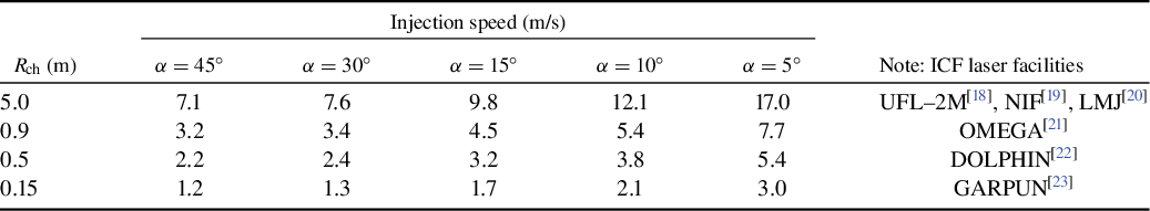
a α is the angle in degrees at which the CFT is injected into the reaction chamber.
2 Experimental setup
To achieve the values specified in Table 1, the first stage of a linear HTSC-MAGLEV accelerator is being created at the LPI.
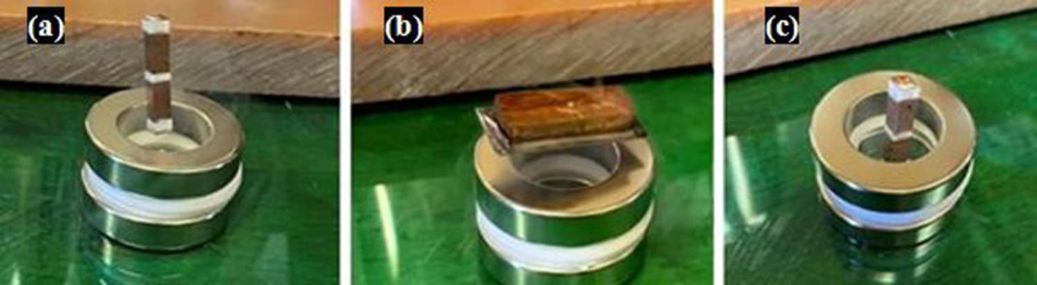
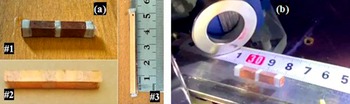
The setup includes the following main components: simple and tandem HTSC–carriers and the HTSC-MAGLEV accelerator. Three models in the form of a hollow parallelepiped (cross-section forms a square) were used: model #1, size 25 mm × 4 mm × 4 mm, mass 0.97 g; model #2, 37 mm × 4 mm × 4 mm, 0.29 g; model #3, 50 mm × 4 mm × 4 mm, 0.55 g (Figure 1). The HTSC–carriers were made from second-generation high-temperature superconductor (2G-HTSC) tapes[ Reference Lee, Petrykin, Molodyk and Samoilenkov 24 ] with a J-PI-04-20Ag-20 Cu structure and a critical superconducting temperature T C ~ 92 K. As 2G-HTSC tapes are Type-II superconductors they allow the magnetic flux lines penetration through their bulk when the applied magnetic field B is B C1 < B < B C2, where B C1 and B C2 are the critical magnetic fields. The penetration of flux lines produces the flux vortices (the so-called Abrikosov vortices[ Reference Abrikosov 25 ]), the state of which appears as ‘frozen’ in the volume of the superconducting material, and any spatial motion of the superconductor will lead to the motion of the magnetic flux line associated with the vortexes. According to Lenz’s law, when an electric current is induced due to a changing magnetic field the direction of the induced current will always oppose the change in the field that caused it. Thus, the effect of the ‘frozen’ flux (flux pinning effect or quantum locking phenomenon) allows fixing the HTSC sample in space, which leads to levitation stability of the acceleration process[ Reference Abrikosov 25 – Reference Landau and Lifshitz 27 ].
HTSC–carriers used in the experiments. (a) General view of three carriers models at room temperature (T = 300 K). (b) HTSC–carrier during levitation (model #1, T ~ 80 K).
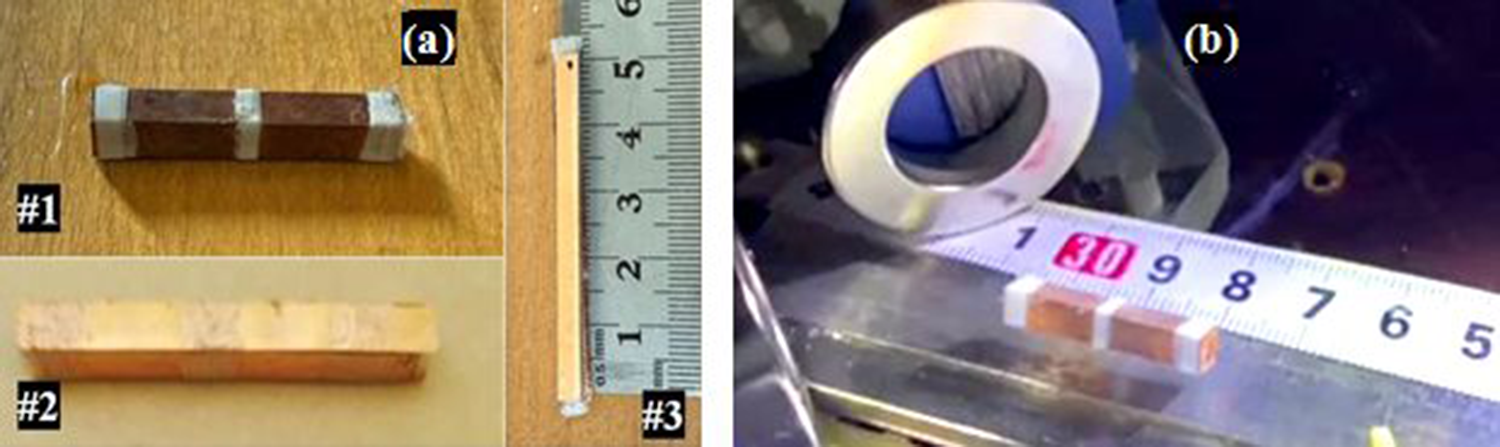
During levitation, the HTSC–carrier was maintained at a temperature of 80 K < T C ≈ 92 K using a polymer foam saturated with liquid nitrogen (T = 77 K) and placed inside it (Figure 1(a), model #3). The experiments have confirmed that 2G-HTSC tapes[ Reference Lee, Petrykin, Molodyk and Samoilenkov 24 ] can be successfully used to maintain a friction-free motion of the HTSC–carriers, and also to provide the required stability of the levitation height over the whole acceleration length due to the flux pinning effect.
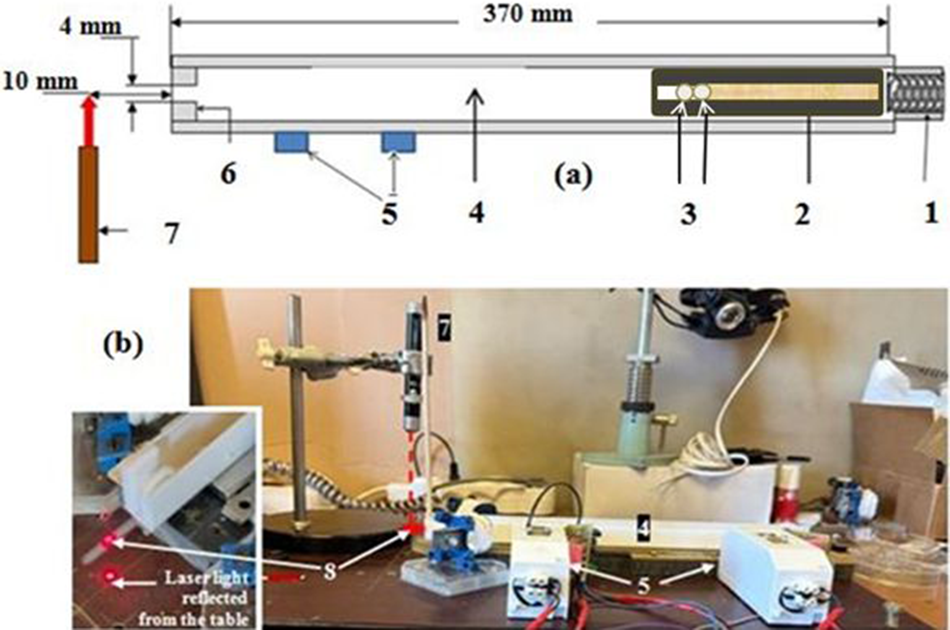
A schematic (a) and a general view (b) of the spring HTSC-MAGLEV accelerator: 1, spring trigger mechanism; 2, HTSC–carrier (T = 80 K); 3, two surrogate targets (glass beads of 3 mm in diameter); 4, magnetic track (T = 300 K); 5, optical sensors for speed measurements of the HTSC–carriers; 6, mechanical brake and injector nozzle (just at the point two surrogate targets leave the carrier); 7, laser semiconductor diode (λ = 650 nm); 8, injected target (during the HTSC–carrier mechanical braking, both surrogate targets begin to move forward by inertia).
The HTSC-MAGLEV accelerator consists of four units (Figure 2) as follows.
-
— Permanent magnet guideway (PMG) system with a magnetic track with the following parameters.
-
• Size 360 mm × 24 mm × 5 mm.
-
• Permanent magnets with an axial magnetization are oriented S-N-S on the track to produce a large cross-sectional gradient ΔВ at the edges of the track forming the so-called ‘magnetic wall’[ Reference Ginzburg and Andryushin 26 ] (in our case ΔВ = 0.33 T).
-
• Permanent magnets are covered in the middle with an iron collector to guide and concentrate the magnetic flux onto the working magnet surface.
-
• Such magnetic track architecture is due to the fact that much of the stability during acceleration comes from placing the HTSC–carrier in a magnetic field gradient when there is a strong gradient in one direction and no gradient in the others. For this case, in the PMG construction the magnetic track must allow the HTSC–carriers to move freely only in one direction on account of the existing cross-sectional magnetic-induction gradient according to the following formula[ Reference Landau and Lifshitz 27 ]:
-
 $$\begin{align*}F=\frac{\chi }{2{\mu}_0}{V}_{\mathrm{S}}\frac{\mathrm{d}B_y^2}{\mathrm{d}y},\end{align*}$$
where μ
0 is the permeability of vacuum, V
S is the superconductor volume and ${\mathrm{d}B}_y^2/ \mathrm{d}y$
is the cross-sectional gradient of the magnetic induction. Recall that superconductors are classified as diamagnetic materials with a magnetic susceptibility χ < 0. This allows one to avoid any contact of HTSC–carriers with a stronger magnetic field, which pushes them out and returns them to their initial trajectory.
${\mathrm{d}B}_y^2/ \mathrm{d}y$
is the cross-sectional gradient of the magnetic induction. Recall that superconductors are classified as diamagnetic materials with a magnetic susceptibility χ < 0. This allows one to avoid any contact of HTSC–carriers with a stronger magnetic field, which pushes them out and returns them to their initial trajectory.
-
— The trigger system includes a spring mechanism for driving the HTSC–carrier. This is a tightly wound spring about to explode (8-mm-diameter spring and 4-mm diameter in a compressed state, its height is 15-mm maximum, four turns).
-
— An optical system for tracking the HTSC–carrier and injected targets during their motion.
-
— Separation module between the HTSC–carrier and target, including a mechanical brake and an injector nozzle.
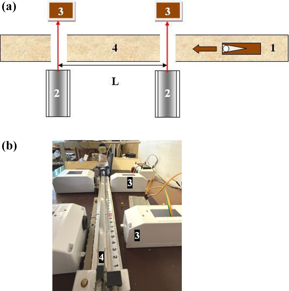
The processes of both acceleration and deceleration of the levitating HTSC–carrier can be carried out either by mechanical or electromagnetic action[ Reference Souers 4 ]. In this work, the carrier driving in the HTSC-MAGLEV system was provided by mechanical action based on a spring mechanism. A schematic and a general view of the experimental setup are shown in Figure 2. The magnetic track is a simple combination of neodymium-iron-boron magnets and sheet steels. It consists of nine rectangular magnets with axial magnetization and residual magnetic induction of 1.45 T. The magnet size is 120 mm × 8 mm × 4 mm. The middle three magnets are covered with an iron plate (magnetic flux line collector) having a size of 340 mm × 10 mm × 0.5 mm. All construction lies on an iron base with a size of 360 mm × 24 mm × 1 mm. The cross-sectional gradient is ΔВ = 0.33 T. Directly above the magnetic track, a 24-mm-wide plastic limiter is installed, at the end of which a mechanical brake is mounted with a vertical 4.0-mm-wide nozzle for the flight of the injected target. The speed of the HTSC–carrier was measured according to the optical scheme shown in Figure 3. After synchronization, each radiation detector located at a certain distance L from the others records the moments of intersection of the HTSC–carrier with a laser beam: t 1 and t 2. Hence, the HTSC–carrier speed can be simply defined as v = L/Δt. The accuracy of determining the coordinates is ±1 mm at a base distance L = 200 mm. The accuracy of determining the radiation detector response is ±20 μs. The speed measurements of the HTSC–carriers of different geometry in the HTSC-MAGLEV accelerator showed values in the range of 2.8–7.1 m/s.
Speed measurements of the HTSC–carriers: (a) optical scheme (1, HTSC–carrier; 2, continuous light of the laser semiconductor diode (λ = 650 nm); 3, laser radiation detector; 4, magnetic track); (b) optical sensor arrangement in the HTSC-MAGLEV accelerator.
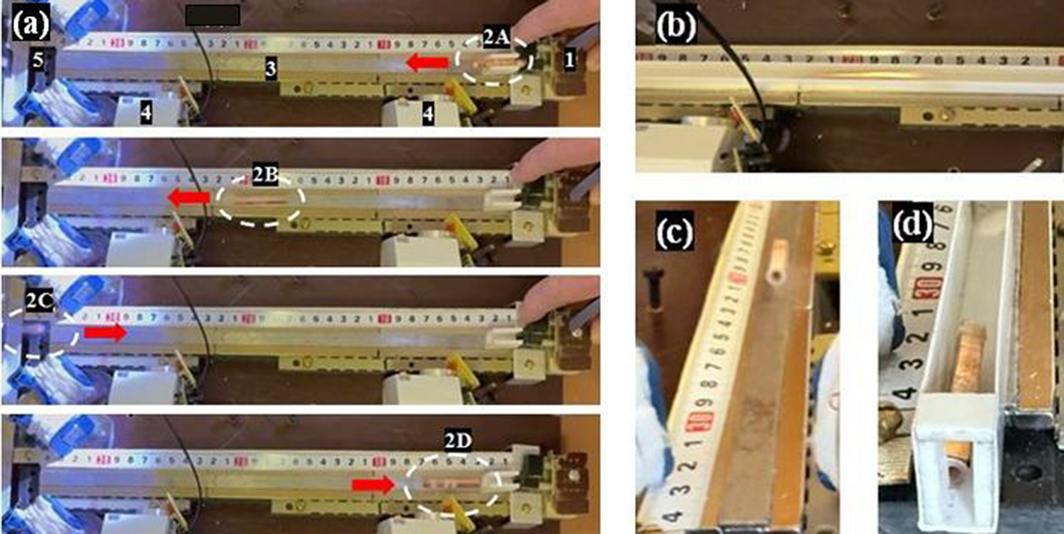
Alignment of the magnetic track was tested experimentally (Figure 4) using the spring HTSC-MAGLEV accelerator (Figure 2). The cartridge (1) of the trigger mechanism contains the HTSC–carrier (pos. 2A), which is fired for its placement over the magnetic track (3). The HTSC–carrier begins to levitate along the magnetic track (pos. 2B) to the end point (5), in which it is mechanically reflected (pos. 2C) and then it returns to the beginning of the path (pos. 2D). Thus, we have a levitating HTSC–carrier, which is free to move back and forth exactly along the magnetic track. In this case, the magnetic gradient ΔВ = 0.33 T limits its deviations in the transverse direction from the given trajectory.
Testing of the magnetic track alignment. (a) 1, spring trigger mechanism; 2, HTSC–carrier (A, HTSC–carrier at the start of its guide lane; B, HTSC–carrier in the middle of the magnetic track; C, HTSC–carrier reflection at the magnetic track end; D, return of the HTSC–carrier at the starting position); 3, magnetic track; 4, HTSC–carrier speed sensors; 5, mechanical brake. (b) HTSC–carrier levitation at v ~ 7 m/s (model #2). (c) HTSC–carrier with a target nest from a full-density polymer levitates at v ~ 3 m/s (model #3). (d) HTSC–carrier in front of the nozzle after the target injection.
3 Results and discussion
The following results were obtained in the experiments.
-
— The HTSC–carrier-like tandem was used (two surrogate targets inside one carrier).
-
— The speed of the HTSC–carrier for one stage of the MAGLEV accelerator was in the range of 1.2–7.1 m/s, which falls within the range given in Table 1. The low speeds correspond to a manual start-up of HTSC–carrier motion.
-
— The gap between the HTSC–carrier and a magnetic rail did not vary with time, that is, the levitation drift during the HTSC–carrier motion is absent.
-
— The injection rate was in the range of 10–25 Hz. It depends on the material from which the target nest inside the HTSC–carrier is made.
-
— The acceleration of the HTSC–carrier with subsequent braking and then an injection of two surrogate targets (glass beads) was recorded (Figures 5 and 6). The time interval between the injection of the two targets was approximately 0.1 s (Figure 5, the target nest inside the HTSC–carrier is from a foam polymer) and 0.04 s (Figure 5, the target nest from a full-density polymer), which correspond to injection rates of approximately 10 Hz and approximately 25 Hz, respectively.
-
— In the experiments, a hard braking was carried out mechanically, but the possibilities of soft electromagnetic influence on the deceleration process were discussed (Figures 7 and 8).
-
— These results are the basis for high-repetition injection of solid spherical polymer beads (polystyrene, deuterated polystyrene and some others) with different diameters.
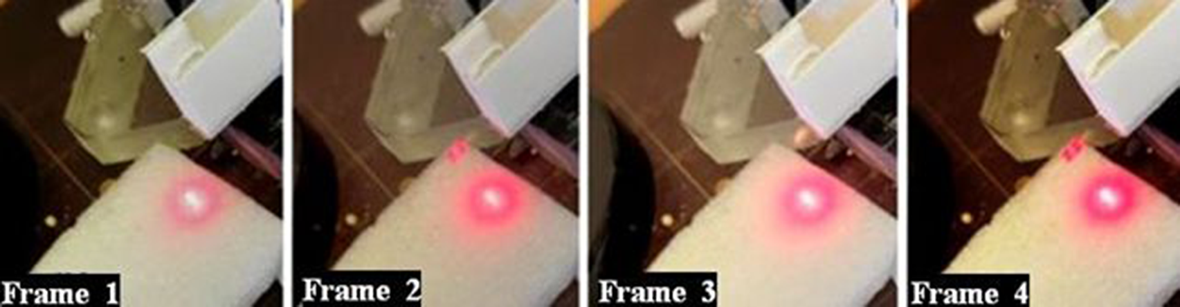
Two targets subject to injection at a rate of 10 Hz using a tandem HTSC–carrier (model #3): frame 1, before injection; frame 2, the first injected target crosses the laser light; frame 3, the moment of second target injection; frame 4, the second injected target crosses the laser light.
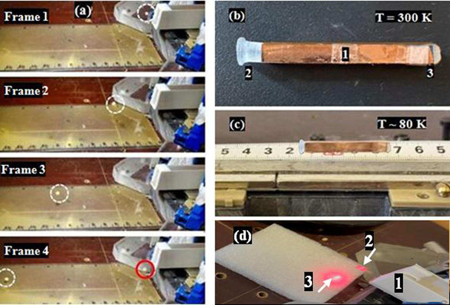
Two targets subject to injection at a rate of 25 Hz using a tandem HTSC–carrier (model #3). (a) Frame 1, the point of the first target injection (shown with a white dotted line); frames 2 and 3, first target in flight; frame 4, the point of the second target injection (shown with a red solid line). (b) General view of the tandem HTSC–carrier (1, HTSC–carrier housing; 2, target nest from a full-density polymer; 3, polymer foam for saturating with liquid nitrogen). (c) Tandem HTSC–carrier levitation. (d) The moment when the first injected target leaves the braking section (1, output of the braking section; 2, target; 3, laser light reflected from the table).
Vertical deceleration of the HTSC–carrier of a hollow parallelepiped type with a polymer foam saturated with liquid nitrogen in a gradient magnetic field.
Proof-of-principle experiments: HTSC–carrier braking using magnets located at an angle (a)–(d) or parallel (f) with each other (1, magnets; 2, magnetic track; 3, HTSC–carrier). (a) HTSC–carrier during motion at 1.2 m/s. (b) HTSC–carrier during successful braking. (c) Changing the direction of the magnetic field allows the HTSC–carrier to be turned by 90°. (d) HTSC–carrier during motion at 3.2 m/s without braking by magnets located at an angle to each other. (e) HTSC–carrier at 3.2 m/s freely passes through the entire braking zone at parallel magnet locations too.
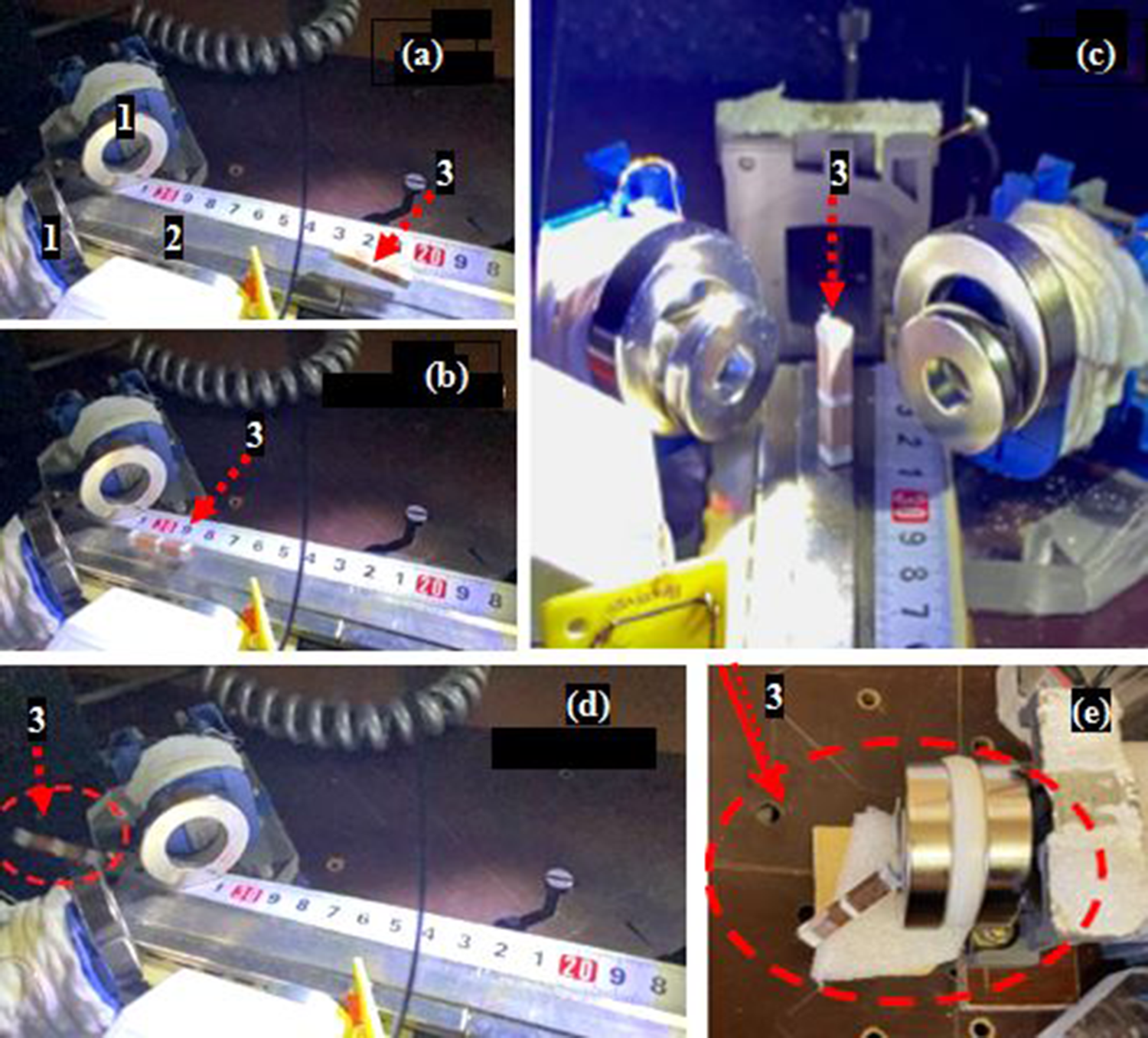
Figure 5 demonstrates stop-frames of the video recording of two targets subject to injection one after the other obtained in the continuous light of a semiconductor laser diode (LD) (wavelength λ = 650 nm). The target nest is made from a foam polymer. The time interval between the two targets being injected is approximately 0.1 s, and the injection rate is 10 Hz.
Figure 6 demonstrates stop-frames of the video recording of two targets subject to injection one after the other. The target nest is made from a full-density polymer. The time interval between the two targets being injected is approximately 0.04 s, and the injection rate is 25 Hz.
The obtained results relate to our new approach – using tandem HTSC–carriers containing two or more targets with the aim to reduce the number of injectors and increase the time interval between their activations.
Ending this section we note that a hard braking after a powerful acceleration, which will be essential attributes of the CFT delivery in future experiments, can be a big problem for IFE reactors. This is due to the fact that a fragile CFT must survive the deceleration process without damage. Therefore, in the near future a step-change in deceleration technology will be needed to meet the 10-Hz requirements for reactor-scaled CFTs. We have started with a soft electromagnetic option of the carrier deceleration and performed the proof-of-principle experiments.
Since the braking process is a part of the separation process between the HTSC–carrier and the target, we will consider just the electromagnetic option when the properties of HTSC materials can be used optimally for both separation and braking operation. In the process of separation, which can be done with a set of permanent magnets or field coils, the HTSC–carrier drops its velocity during its motion in the growing magnetic field according to Equation (1) , while the target keeps its velocity moving forward by inertia (the target is nonmagnetic and it is not affected by the magnetic field).
In this regard, we made changes in the design of the separation module of the HTSC-MAGLEV accelerator shown in Figure 2. The principle of its operation is shown in Figure 7. To influence the HTSC–carrier, two ring permanent magnets based on neodymium-iron-boron (NdFeB) with an anti-corrosion coating of Ni-Cu-Ni (nickel) were used. The magnet dimensions are as follows: outer diameter – 35 mm, inner diameter – 20 mm, height – 8 mm. The residual magnetic induction B = 1.4 T. The HTSC–carrier is thrown vertically from a height of 10 cm with a zero initial velocity (on the ground its speed is 1.4 m/s). During free fall it enters the increasing magnetic field. As the HTSCs are diamagnetic, the HTSC–carrier is pushed out from the area of a stronger magnetic field.
Under these conditions the carrier stops and becomes suspended over a magnet at a certain height (Figure 7(a)). This height does not change unless the HTSC–carrier temperature changes. Its value depends on the time before the HTSC warms from T ~ 80 K back up to the transition temperature T C ~ 92 K. To avoid rapid heating, different insulation materials were used in the experiments. For models in the form of a hollow parallelepiped it is polymer foam saturated with liquid nitrogen (Figures 7(a) and 7(c)). For models in the form of an open parallelepiped (length inside, 25 mm; width inside, 8 mm; height, 4 mm; total mass 1.25 g; see Figure 7(b)) liquid nitrogen (boiling point 77 K) was poured directly into the HTSC–carrier (Figure 7(b)). Obviously, the case shown in Figure 7(b) is preferable – the height does not change for a long time until the liquid nitrogen boils away. To achieve such results for the hollow parallelepiped carriers, it is planned to use new HTSC materials with porosity above 50%. The pores in such HTSCs provide a better penetration of the coolant, efficient heat removal and stable operation[ Reference Gokhfeld, Koblishka and Koblishka-Venev 28 ].
Figure 8 presents a proof-of-principle demonstration of the method of braking the HTSC–carrier to separate a target with the same permanent magnets as in Figure 7. To manipulate the rate of horizontal braking one must adjust either the magnitude or duration of magnetic force (braking impulse) applied in the horizontal direction to provide stable and smooth movements of the HTSC–carrier in the HTSC-MAGLEV accelerator (Figure 8). In our case, the magnets were located at an angle or parallel with each other. The speed of the HTSC–carrier was 1.2 m/s (Figures 8(a)–8(c)) and 3.2 m/s (Figures 8(d) and 8(e)). Note that in the process of magnetic braking, three main parameters play a role: temperature, HTSC–carrier speed and magnetic force field (Br × dBr /dr, where r is a coordinate directed along the acceleration length). Since in our experiments the braking time was about 1 s, the influence of temperature can be excluded.
The results of demonstrating the magnetic braking impulse are as follows: (1) if the HTSC–carrier speed is less than 1.5 m/s, then the carrier braking is successful; (2) otherwise, the HTSC–carrier flies through the magnetic field without braking regardless of how the magnets are located.
Figure 8(c) shows how to change the HTSC–carriers’ orientation to remove them from the HTSC-MAGLEV accelerator after target injection. This is an important step in the development of the HTSC–carrier separation module, whose operation is based on using a special coil with a pulsed, repetitively cycled signal to direct the used HTSC–carriers into a special collection system.
Thus, to manipulate the HTSC–carrier braking or its orientation for removing it from the acceleration system it is necessary to create the required magnetic field gradient for a given HTSC–carrier speed. For existing laser facilities these values are not high (v inj = 3.2–17 m/s; T ch = 300 K and R ch = 1–5 m[ Reference Aleksandrova, Akunets, Agapov, Koresheva and Nikitenko 16 ]). However, for the IFE reactor (v inj = 200−400 m/s; T ch ~ 1758 K and R ch ~ 6 m)[ Reference Goodin, Alexander, Brown, Frey, Gallix, Gibson, Maxwell, Nobile, Olson, Petzoldt, Raffray, Rochau, Schroen, Tillack, Rickman and Vermillion 15 ]) it is important to highlight that the optimization of the braking impulse will require a high level of technical ability.
4 Conclusion
A step-change in CFT injection technology is required to meet the ICF/IFE requirements for high-repetition-rate conditions. This is now being realized at the LPI in the development of HTSC-MAGLEV technologies for injection delivery of CFTs at the laser focus both in single and repeatable modes. Our approach is based on the phenomenon of quantum levitation of a superconducting target carrier (HTSC–carrier) in gradient magnetic fields. To meet these challenging high-repetition-rate requirements, a setup for demonstrating the injection capabilities was built using spring launch technology combined with MAGLEV, allowing no heat energy transfer into the CFT from the accelerating medium. In doing so, CFT overheating will be excluded in terms of loss of quality of the D-T layers, and the service life of the delivery system will be extended, especially when it operates under high-repetition-rate conditions. Experiments and modeling have confirmed the prospects of this approach[ Reference Miquel, Batani and Blanchot 20 ]. In this work, we used the created setup with the magnetic track having a cross-sectional induction gradient ΔВ = 0.33 T to provide the required stability of the levitation height over the whole acceleration length. A series of injection tests was conducted to verify the tandem HTSC–carrier configuration. The motion of the tandem HTSC–carrier containing two surrogate targets was recorded, followed by its mechanical braking and targets subject to injection with a rate of 10 Hz (target nest from a foam polymer) and 25 Hz (target nest from a full-density polymer). Because in IFE experiments a fragile CFT must survive the braking process without damage, the potentials of soft electromagnetic braking were also analyzed. Proof-of-principle experiments have shown the possibility to manipulate both the magnetic braking of the HTSC–carrier and its orientation after separation between the target and HTSC–carrier[ Reference Aleksandrova, Koresheva and Akunets 29 , Reference Koresheva, Aleksandrova, Agapov, Akunets and Nikitenko 30 ]. The latter is a necessary element when creating the HTSC–carrier separation module to remove the used carriers from the HTSC-MAGLEV accelerator. Further developments in this direction will allow planning unique experiments on a uniform, spherically symmetric laser irradiation of CFTs injected into the reaction chamber of existing laser facilities capable of ignition-level performance.
Acknowledgements
This work was performed within the framework of the State Assignment of the Lebedev Physical Institute and discussed at the 30th IAEA Fusion Energy Conference 2025[ 21 ].


 Open access