
I. INTRODUCTION IN REGION OF INTEREST (ROI) CODING
For aerial surveillance tasks, e.g. for disaster area monitoring as well as for police surveillance operations, unmanned aerial vehicles (UAVs) become more prevalent nowadays. One of the main challenges hereby is the transmission of high-resolution image data recorded on-board the UAV over channels with only limited capacities. Taking into account the high resolutions of today's and upcoming camera sensors (4 K and above), and the demand for multiple or multi-view video streams, efficient data compression is of growing interest. In this work, we aim at providing high image quality for the transmission of high-resolution video sequences (HDTV) at low bit rates.
A) Related work
Trivial approaches transmit high-resolution video data from UAVs to the ground by simply using broader channels like Wi-Fi or using a high-image compression ratio targeting low bit rates. This either results in the disadvantage of very limited range of operation (in the case of e.g. Wi-Fi) or results in poor image quality and the possible loss of interesting image content [Reference Ciubotaru, Muntean and Ghinea1].
1) ROI coding
In order to reduce the bit rate after encoding while maintaining interesting image content, ROIs coding is commonly applied, spatially dividing each frame of a video sequence into ROIs and non-ROIs. Hereby, the quality of ROIs is left untouched. Non-ROI areas of a frame could be blurred in a preprocessing step prior to actual video encoding or coarsely quantized within the video encoder itself to reduce the overall bit rate [Reference Karlsson, Sjöström and Olsson2–Reference Chen, Chi, Hsu and Chen4]. A modified or externally controllable block-based hybrid video coder like Advanced Video Coding (AVC) [5] or High-Efficiency Video Coding (HEVC) [6] is employed in [Reference Liu, Li and Soh7–Reference Wu and Su10] and [Reference Xing, Tian, Huang and Gao11,Reference Meddeb, Cagnazzo and Pesquet-Popescu12], respectively, in order to apply different QPs for the coding of ROI and non-ROI blocks.
The drawback of ROI detection and coding approaches discussed above is the degradation of non-ROI areas that cannot be reconstructed at full quality at the decoder. The modular ROI detection and coding system introduced and extended in our earlier publications [Reference Meuel, Munderloh and Ostermann13,Reference Meuel, Schmidt, Munderloh and Ostermann14] and [Reference Meuel, Reso, Jachalsky and Ostermann15] exploits the characteristic of aerial video sequences on a planar landscape to overcome this drawback and maintains full resolution and high-quality video over the entire frame at low bit rates. It relies on the transmission of only new emerging image content (New Areas, ROI-NA) for each of the frames, which are stitched together in a mosaicking post-processing step at the decoder to reconstruct the static parts of the scene (background) by means of global motion compensation (GMC) [Reference Meuel, Munderloh and Ostermann13,Reference Meuel, Schmidt, Munderloh and Ostermann14]. Since only small parts of each frame have to be transmitted, this ROI detection and coding system is capable of providing high image quality at low bit rates. Since other approaches introduced here are not able to reconstruct the background in full quality at bit rates considerably lower than those of a common state-of-the-art video encoder, we use this system as a basis. It is described in detail in Section II.
2) ROI detection
Although, theoretically, ROIs can be arbitrarily defined, e.g. in the center of the image or by detecting skin color in a teleconferencing system like in [Reference Terrillon, David and Akamatsu16], more context-sensitive approaches are desirable. For aerial surveillance scenarios, moving objects (MOs) are often considered as ROI, further on referred to as ROI-MO. Most of the recent work in the field of surveillance video processing, especially for automatic MO detection, relies on a static (non-moving) camera, e.g. [Reference Sakaino17–Reference Zhang, Tian, Huang, Dong and Gao20] and consequently cannot deal with camera ego-motion. Hence, those approaches are not suitable for aerial surveillance tasks with the camera attached to a UAV.
Popular approaches rely on the GMC of the background pixels due to the camera movement prior to calculate the pelwise image differences (difference image) between two frames of the image sequence or between the current frame and a reconstructed background reference image [Reference Jones, Ristic, Redding and Booth21–Reference Ibrahim, Ching, Seet, Lau and Czajewski24]. More efficient detectors can also handle non-perfect conditions like parallax effects by employing the epipolar geometry [Reference Kang, Cohen, Medioni and Yuan25]. Other approaches are based on optical flow analysis in order to detect MO [Reference Yalcin, Hebert, Collins and Black26]. In [Reference Teutsch and Kruger27], image features are classified as stationary or moving on the ground, clustered and finally tracked over several frames. The clustering itself is based on morphological filtering of a binarized difference image [Reference Kumar28,Reference Teutsch29] provide an extensive overview on recent publications in the field of aerial surveillance systems from moving cameras.
However, since the image signal itself is not considered in any of the above MO detection strategies, the shape of MOs cannot be detected accurately, especially in homogeneous areas within MO (e.g., car roofs). Moreover, since MO are often detected on a frame-by-frame basis, missing detections in single frames lead to entire ROIs not being detected.
To overcome these limitations of the MO detection results and the image signal [Reference Mundhenk, Ni, Chen, Kim and Owechko30], uses the difference image-based MO detection results as seeds for a mean shift clustering [Reference Comaniciu and Meer31] in order to accurately determine the shapes of MOs. In [Reference Xiao, Cheng, Feng and Yang32], MO detection is performed by processing the difference image between an affine motion compensation and an optical flow estimation. Based on the detected blobs, GraphCut is employed as a signal-dependent segmentation method to determine the shapes of MOs in the input video frame. In our previous work [Reference Meuel, Reso, Jachalsky and Ostermann15], we showed that a superpixel segmentation [Reference Reso, Jachalsky, Rosenhahn and Ostermann33] is able to outperform a GraphCut method in a MO detector. By additionally exploiting the temporal consistency of these superpixels, we were able to handle the problem of temporally missing detections of MOs in single frames. Based on [Reference Meuel, Reso, Jachalsky and Ostermann15], we further reduced falsely as static classified MOs due to motion parallax in [Reference Meuel, Munderloh, Reso and Ostermann34] by replacing the background motion compensation within the MO detector by a mesh-based motion compensation and a clustering of displacement vectors [Reference Munderloh35].
Thus, we decided to use our MO detection and ROI-based coding system from [Reference Meuel, Munderloh, Reso and Ostermann34] as a basis for extension with an efficient modified HEVC video encoder.
The contributions of this work are:
(1) We summarize our previous work [Reference Meuel, Munderloh and Ostermann13,Reference Meuel, Reso, Jachalsky and Ostermann15,Reference Meuel, Munderloh, Reso and Ostermann34,Reference Munderloh, Meuel and Ostermann36] and thoroughly describe the complete MO detection and coding system for the low bit rate transmission of high-resolution aerial video sequences in detail.
(2) We review the mesh-based motion compensation and the mesh-based cluster filter for the reduction of non-MOs, falsely classified as moving from [Reference Meuel, Munderloh, Reso and Ostermann34], and present previously unpublished details of the cluster filter in Section IV-A.
(3) We show a more detailed evaluation of the MO detector including receiver operation characteristics (ROCs) for different test sequences, also considering the publicly available VIRAT test data set [37,Reference Oh38].
(4) We propose to integrate a modified HEVC video encoder in the coding system and evaluate the performance compared to the AVC-based video encoder employed in our previous work as well as to an unmodified HEVC encoder. In order to analyze the maximum coding performance of the proposed video encoder, we use more test sequences containing no MOs in a second test set.
(5) Finally, we present a run-time analysis for each component in order to underline the suitability of the proposed system for usage on-board an UAV.
The remainder of this work is organized as follows: In Section II, we review the ROI-based coding system for low bit rate transmission of aerial video and introduce our adaption of HEVC as video encoder (Fig. 1: brown) to exploit the improved coding efficiency of HEVC compared to AVC. In Section III, we describe the integration of superpixels in the system. In Section IV, we explain our mesh-based MO detector in detail, employing our cluster filter approach for reliably distinguishing non-moving and MOs and a mesh-based motion compensation for the compensation of non-planar structures. In the experimental results in Section V, we present results of the improved MO detection system for an extended test set (compared to our previous work [Reference Meuel, Munderloh, Reso and Ostermann34]) in terms of detection accuracy (Section V-B), coding efficiency (Section V-B) as well as run-time (Section V-C). In order to demonstrate the maximum coding efficiency of the modified HEVC video encoder, we use a second, publicly available test set [39], containing self-recorded high-resolution aerial sequences without MOs. Section VI concludes this work.
Block diagram of ROI detection and coding system: Bold framed block: proposed cluster filter to eliminate false positive (FP) detections; white: optical flow; yellow: mesh-based motion estimation/compensation incl. ROI detector; magenta: superpixel segmentation and selection; green: global motion estimation and new area detector; brown: block generation, video coder and muxing (based on [Reference Meuel, Munderloh, Reso and Ostermann34]).

II. OVERVIEW OF THE PROPOSED ROI CODING SYSTEM FOR AERIAL SURVEILLANCE VIDEO
The entire block diagram of the ROI coding system for aerial surveillance video sequences including all proposed improvements is depicted in Fig. 1 (based on [Reference Meuel, Munderloh, Reso and Ostermann34]). In order to visualize each processing step, we also integrated preview images into the block diagram. We will introduce all components and explain the entire pre-processing procedure needed prior to the actual video encoding within this subsection at appropriate positions.
Assuming a planar landscape, the camera motion between the recorded frames at the encoder on-board the UAV can be estimated. This estimated motion is transmitted as projective transformation parameters to the decoder at the ground station. Assuming a first, regularly coded frame by the encoder, these parameters are used to predict the current frame from already known video frames by applying a GMC of the background. Since the background can be reconstructed at full quality by means of GMC, no additional transmission cost is necessary for already transmitted background for any predicted frames. Image content which is not reconstructed by the global motion model, such as newly visible background (New Area, ROI-NA) or MOs (ROI-MO), is transmitted using an externally controlled arbitrary video codec, e.g. AVC (also known as H.264 or MPEG-4 part 10), or HEVC. Compared to a block-based motion compensation, we can reconstruct a high-quality image without blocking artifacts with our GMC approach.
As a basis for further processing, we derive the global motion out of the video frames as follows: A pel  $\vec{p}=(x,y)^{\top}$ in frame k can be mapped on a corresponding coordinate $\vec{p}'=(x',y')^{\top}$ in the preceding frame k−1 using the projective transformation $F \lpar \vec{p},\vec{a_{k}} \rpar $ (equation (2)) with the projective transformation parameter set $\vec{a_{k}}$ (equation (1)).
 $$a_k = (a_{1,k}, a_{2,k}, \ldots, a_{8,k})^\top,$$
 $$\eqalign{ F \lpar {\vec{p}},{\vec{a_k}} \rpar = & \left({a_{1,k}\cdot x+a_{2,k}\cdot y+a_{3,k}\over{a_{7,k}\cdot x+a_{8,k}\cdot y + 1}},\right. \cr & \quad \left.{a_{4,k}\cdot x+a_{5,k}\cdot y+a_{6,k}\over{a_{7,k}\cdot x+a_{8,k}\cdot y+1}}\right) ^\top.}$$
Thus, one plane, i.e. one frame, can be mapped into another with the projective transformation, whereas the parameters a 3 and a 6 express translational movement in direction of x and y. The parameter set is embedded into the bit stream of the video encoder as supplemental enhancement information (SEI). Since only nine floating point numbers per frame are required, the additional bit rate is negligible.
To estimate the global motion, first a Harris Corner Detector [Reference Harris and Stephens40] detects corner features in the current frame k. Secondly, a sparse optical flow (Fig. 1: white) is calculated by a Kanade–Lucas–Tomasi (KLT) feature tracker from frame k to the previous frame k−1 [Reference Tomasi and Kanade41,Reference Shi and Tomasi42]. By employing a projective transformation motion model (equation (2)), Random Sample Consensus (RANSAC) is able to estimate a set of projective transformation parameters for the mapping of all pixels from frame k−1 to frame k while removing the outliers [Reference Fischler and Bolles43] (Fig. 1: green). Using this parameter set, New Area is computed as the image regions not contained in the frame k−1 but in the current frame k (on a pelwise basis). These regions are marked for video encoding in a map of pixels to be coded, further on called the coding mask. For the detection of MOs, the pelwise difference in the luminance channel (Y) between the current frame k and the globally motion compensated prediction  $\hat{k}$ is computed (further referred to as difference image) and spots of high energy are marked as MOs in an activation mask.
A) Increase of true positive detections of MOs by integrating temporally consistent superpixel in the MO detector
Such difference image-based MO detectors lack accuracy when it comes to unstructured, homogeneous regions within the MOs – e.g. car roofs – as for those areas where the pixel differences between the current and the motion compensated frame are relatively small [Reference Bang, Kim and Eom19]. Figure 2 illustrates occurring problems: if parts of a MO (original in Fig. 2(a)) are detected as ROI whereas other parts of the same MO are not recognized (Fig. 2(b)), reconstruction errors might occur since the motion compensated ground (background) and foreground (ROI) might not match exactly, leading to errors in the reconstructed video (Fig. 2(c)) [Reference Meuel, Reso, Jachalsky and Ostermann15]. We identify MO areas more accurately by combining an independently calculated superpixel segmentation with the difference image-based detector result (Fig. 3, middle and bottom row): the results from the difference image-based detector are used as seeds to automatically activate only those superpixels containing MOs. Additionally, by using a temporally consistent superpixel (TCS) segmentation our system is able to bridge temporal detection gaps, thus reducing the amount of missed detections per frame (see also Fig. 4 in Section III-A for illustration). As shown in [Reference Meuel, Reso, Jachalsky and Ostermann15], the TCSs are able to outperform other state-of-the-art segmentation methods like an efficient GraphCut-based SlimCut implementation [Reference Scheuermann, Rosenhahn, Boykov, Kahl, Lempitsky and Schmidt44]. The TCS segmentation itself [Reference Reso, Jachalsky, Rosenhahn and Ostermann33] and the integration into the detection system [Reference Meuel, Reso, Jachalsky and Ostermann15] (Fig. 1: magenta) are described in Section III.
Original outtake (a) and reconstructed image after ROI encoding and decoding (c) with inaccurate MO detection due to homogeneous, unstructured regions on the car roof. Missing detections (b) of the rear part of the red car as ROI lead to reconstruction errors since the front part of the car (ROI) does not match the reconstructed background [Reference Meuel, Reso, Jachalsky and Ostermann15].
Coding mask generation for new area (top row) and MOs. The MO activation mask from the difference image calculation is overlaid with an independent Superpixel segmentation in order to get accurate shape information of the MOs. The Coding mask is adapted to a coding block pattern (MO block coding mask) and combined with the NA block coding mask to the Final block coding mask. Cyan and green blocks in the latter will be encoded as ROI.
Temporally consistent superpixels (TCSs) are used to bridge false negative detections of the ROI-MO: if no MO (white car) is detected by the MO detector (cyan), the MO in frame k−1 would not be selected for coding. Due to the temporal consistency of the superpixels the position of the car can also be predicted in frame k−1 and thus correct processing and transmission of the car in all frames can be guaranteed.
B) Reduction of FP detections of MOs by integrating a mesh-based MO detector
Given the use of the projective transformation, we must assume a planar ground which is (prevalently) true for sequences recorded at high flight altitudes. This assumption is not suitable for non-planar ground structures like buildings or trees. These lead to image regions falsely detected as MO false positive (FP) detections resulting in an increased ROI area. Consequently an increased number of superpixels is selected for encoding. For the MO detection, we propose to replace the planar GMC by a mesh-based motion estimation and compensation [Reference Munderloh, Meuel and Ostermann36]. Instead of one global plane for the full frame, multiple smaller planes are used to enable the motion compensated image to adapt to non-planar scene geometry (Fig. 1: yellow) [Reference Meuel, Munderloh, Reso and Ostermann34]. We describe the mesh-based local motion estimation and compensation as well as a locally adaptive outlier detector (Fig. 1: yellow) for MO detection to deal with non-planar areas in Section IV [Reference Meuel, Munderloh, Reso and Ostermann34].
C) Further reduction of the bit rate by introducing an HEVC video encoder
Whereas the reference system in [Reference Meuel, Munderloh, Reso and Ostermann34] employs a modified AVC encoder, we propose to replace the video encoder by a recent HEVC encoder in order to gain from the increased coding efficiency of HEVC compared to AVC. The approach to determine which image areas finally have to be encoded (ROI, non-skip mode) and which not (non-ROI, skip mode), remains the same: the pelwise information of ROI-NA as well as ROI-MO is extended to a fixed block grid (macroblock/Coding Unit level). If at least one ROI-NA or ROI-MO pel is located in a 16×16 block, this block is marked for encoding in non-skip mode in a Final block coding mask as shown in Fig. 3 which is used to control the video encoder externally. Since common video coding standards like AVC and HEVC only define the decoding, our encoder control does not affect the (HEVC) standard compliance of the bit stream. However, an additional post-processing is necessary as described above to reconstruct non-ROI areas (static background) of the scene [Reference Meuel, Munderloh and Ostermann13,Reference Meuel, Schmidt, Munderloh and Ostermann14].
The coding gain of our system compared to the encoding of entire frames with an unmodified video encoder depends on the amount of ROI to be encoded. As an upper limit we have to encode the entire frame (e.g. if MOs are all over the frame). In this case the system falls back to encode and to transmit the full frame, resulting in a coding efficiency of the unmodified video coder (anchor). As a lower limit we can encode the entire frame in skip mode, if no UAV motion is prevalent and no MOs are detected within the scene. However, for typical scenarios only a few percent of each frame have to be encoded and transmitted.
We would like to emphasize that single components (e.g., the video encoder, the image segmentation or the MO detector) could be exchanged by similar components without loss of generality or loss of functionality of the entire system.
III. SUPERPIXEL-SEGMENTATION
In order to improve the detection accuracy of non-textured MOs without decreasing the precision, it was proposed in [Reference Meuel, Reso, Jachalsky and Ostermann15] to use superpixels for the context-adaptive enlargement of the activation mask. Superpixel algorithms as initially proposed by Ren and Malik in [Reference Ren and Malik45] group spatially coherent pixels sharing the same color or which are part of the same texture into segments of approximately same size and shape. Their boundaries should comply with appearance boundaries of objects present in the scene. In this work, we use the superpixel segmentation framework proposed by [Reference Reso, Jachalsky, Rosenhahn and Ostermann33] which provides segmentation masks for all frames of the input video. Superpixels occupying the same image region in different frames share the same label establishing a temporal connection between these superpixels.
The framework produces superpixels by clustering pixels using their five-dimensional (5D) feature vector [labxy] containing the three color values in CIE-Lab color space and the pixel's xy-coordinates. To capture the temporal connections between superpixels in different frames, the clustering is performed over an observation window spanning multiple frames. Pixels in different frames being part of the same superpixel should share the same color but not necessarily their position over multiple frames. Therefore, each cluster center (representing one superpixel) consists of one color center and multiple spatial centers (one for each frame in the observation window). In order to represent the image content adequately by a superpixel segmentation, an optimal set of cluster centers  $\Theta_{opt}$ as well as a mapping σi, k of pixels i in frame k to these cluster centers have to be obtained. A cost function (equation (3)) is defined which sums up all distances of the pixels to their assigned cluster center
 $$D_{total} = \sum_{k} \sum_{i}(1-\alpha) D_c(i_k,\sigma_{i,k}) + \alpha D_s(i_k,\sigma_{i,k}),$$
where  $D_{c}(i_{k},\sigma_{i,k})$ and $D_{s}(i_{k},\sigma_{i,k})$ denote the Euclidean distance of pixel i k to the cluster center σi, k in color space and image plane. The spatial distance is normalized by the average superpixel size which depends on the frame resolution and the number of superpixels chosen by the user. The trade-off between color-sensitivity and spatial compactness can be controlled by the weighting factor α. If α is set to 1 no color information is used resulting in Voronoi cells which only depend on the initial positions of the superpixels’ spatial centers. On the other hand, a low α leads to less compact superpixels which vary more in their size and have irregular shapes (for our experiments we set α to 0.96 which was empirically determined in [Reference Reso, Jachalsky, Rosenhahn and Ostermann33]). An approximation of the optimal set $\hat{Theta}_{opt}$ and a corresponding mapping $\hat{\sigma}_{i,k}$ is obtained by applying an alternating expectation–maximization (EM) scheme. In the expectation-step an optimal mapping for the three latest frames in the observation window is obtained by minimizing equation (3). This is done by assigning each pixel to the cluster center for which the weighted sum of color and spatial distances is minimal. In the maximization-step the cluster centers are updated by calculating the mean color and spatial values of the assigned pixels. The expectation- and maximization-steps are alternated five times before the observation window is shifted one frame forward. The connectivity of the superpixels is ensured by a post-processing step. The initialization is done by subsequently filling the observation window with frames while performing several iterations (five in our experiments) of the expectation- and maximization-step after adding a frame. The first frame is initialized by distributing the cluster centers uniformly on the frame. After the observation window finally spans an amount of 15 frames, new frames are inserted into the window. Simultaneously the oldest frame is removed which results in a shift of the observation window.
With the integration of TCSs as described, we are able to accurately segment shapes of MOs. However, in case of missing activations of superpixels due to missing detections from the difference-image-based MO detector, e.g. for slow moving or shortly occluded MOs, those MOs might still not be detected and thus wrongly reconstructed.
A) Bridging short-time missing MO detections by utilizing temporal consistency
In order to activate blocks containing those slow MOs in the coding mask, i.e. to detect MOs which erroneously were not detected in a single frame, but in the surrounding frames, we employ a sliding window approach (Fig. 4): an active superpixel in the current frame within a sliding window width (SWW) will also activate the past and next SWW/2 temporally associated superpixels. SWW=1 represents no superpixel activation propagation, “3” specifies a lookback and a lookahead of one frame each. Thus, besides the propagation of activations into homogeneously colored areas this TCS enhanced system guarantees the accurate detection of MOs in case of short-time missing detections caused by e.g. very slow object movement.
Although the integration of superpixels in the coding system offers several benefits, wrongly detected MOs were erroneously also enlarged by the corresponding superpixels. Thus, we have to ensure a FP detection rate being as low as possible.
IV. REDUCTION OF FP DETECTIONS OF MOS BY MESH-BASED MOTION COMPENSATION AND CLUSTER FILTERING
The GMC uses a projective transformation (homography) to model the movement of the background pixels between the frames originated by the ego-motion of the camera during recording. This model assumes all scene points to lie on the surface of a single plane in three-dimensional (3D) space, i.e. the surface of the earth. This approximation is only valid if the surface of the earth is completely planar or if the distance of the camera to the earth is high and the focal length of the camera is chosen small. Violation of this assumptions e.g. by low flight altitudes, large focal lengths, or non-planar ground structures like buildings or trees result in falsely detected MOs due to the motion parallax effect. The effect describes the difference in displacement of projected pixels between frames of a moving camera and depends on the distance of the scene points to the camera center.
The homography based GMC is only capable of compensating the displacement of projected scene points which are positioned on the surface of a single plane at a specific distance. All scene points not placed on the surface of the plane might result in spots of high energy in the difference images due to their displacement not being perfectly compensated. This results in lots of FP detections of MOs and consequently leads to an unnecessary high bit rate in the ROI coding system. Assuming that several small planes can be better fitted to a non-planar landscape than one plane per frame, we replaced the single plane GMC by a locally adaptive mesh-based motion compensation [Reference Meuel, Schmidt, Munderloh and Ostermann14,Reference Munderloh, Meuel and Ostermann36,Reference Munderloh, Klomp and Ostermann46] for the MO detector only. We approximate the earth surface with a mesh of connected (small) planar triangles, which are called patches further on. Each patch is assumed to be planar and has an individual slope and orientation. This allows the mesh surface to better adapt to non-planar ground structures and parallax effects.
Since the KLT features are designated as nodes of the triangles, the feature points have to be pruned by outliers, such as feature points on MOs.
A) Mesh-based cluster filtering for outlier removal
As with multiple small planes there is no single global homography parameter set to optimize, the RANSAC outlier removal has to be replaced by evaluating the motion of features in a local neighborhood surrounding each of the patches. For this purpose, we have designed a filter which is based on the clustering of motion vectors, gained from the KLT feature tracker, using a region growing approach. Since KLT has to be performed anyway for global motion estimation, no extra effort is necessary to generate these motion vectors. We assume a smooth optical flow field: small changes between adjacent motion vectors suggest them to be part of the same object while discontinuities indicate objects with differing motion. This filter we call cluster filter (CF), as it clusters the optical flow into regions of similar motion [Reference Meuel, Munderloh, Reso and Ostermann34]. To follow small changes in the vector field, the region growing approach assumes clusters to be defined by the motion vectors on their boundaries only: if the spatial distance (equation (4)) of an unclustered motion vector  $\vec{v_{k}}$ in frame k to the closest border motion vector $\vec{c_{k}}$ of an already existing cluster in the same frame is smaller than a threshold t d1 and if furthermore the difference in their displacements $\vec{d_{v}}=\vec{v_{k}}-\vec{v_{k{-}1}}$ and $\vec{d_{c}}=\vec{c_{k}}-\vec{c_{k{-}1}}$ between the frames k and k−1 (equation (5)) is also smaller than a threshold t d2, both vectors are considered similar and the unclustered vector is added to the cluster. The displacement similarity t d2 is hereby scaled by the distance to force a higher similarity for nearby motion vectors:
 $$\Vert \vec{v_k} - \vec{c_k} \Vert \lt t_{d1},$$
 $$\Vert \vec{d_v} - \vec{d_c} \Vert \lt t_{d2} \cdot {\Vert\vec{v_k} - \vec{c_k}\Vert\over{t_{d1}}}.$$
If no further unclustered vector fulfills the similarity condition according to equations (4) and (5) for any cluster, a new cluster has to be founded. The process repeats until every vector is assigned to a cluster. A MO is defined by a common motion and hard discontinuities in the vector field at its borders. Therefore, a MO forms an individual cluster. The displacement vectors on non-planar structures, however, only change slightly and continuously. These changes are relatively small compared to those of real MOs. Therefore, the cluster filter is capable of assigning high objects which protrude from the ground plane into the background motion cluster by simply following the small changes in displacement from the bottom up to the top. As an example imagine a church spire: the ground plane of the church spire will have no displacement caused by motion parallax due to the moving camera. In contrast to that, the maximum displacement at the church top will be very high. Considering only pairwise neighbored motion vectors, starting from the bottom up to the top, the displacement will increase slightly and continuously. The background motion cluster is finally defined as being the largest one in the scene (brown dots in Fig. 5). Only the background cluster is used for motion compensation whereas small clusters are further processed as MO candidates (Fig. 5, blue crosses with purple and white dots). Clusters containing less motion vectors than a threshold t f are considered to be outliers and have to be removed (Fig. 5, blue crosses).
Triangulated mesh (green triangles) between detected features (brown dots: background features, blue crosses: motion candidates including outlier, purple and white dots: detected MOs after cluster filtering) and trajectories (yellow lines) in the motion compensated destination frame [Reference Meuel, Munderloh, Reso and Ostermann34]. Best viewed in color.
B) Mesh-based motion compensation
To define the piecewise planar patches of the mesh from the background motion vector field, a triangle mesh is generated using the feature point coordinates of the background cluster of the frame k given by the cluster filter as nodes for the mesh (see Fig. 6, based on [Reference Munderloh, Meuel and Ostermann36]). As the changes in perspective between the frames are relatively small, an affine transformation is greatly sufficient to compensate the content of each patch. We create a triangle mesh with triangles t i and the feature points as vertices, employing a Delaunay triangulation [Reference Dwyer47] using the Guibas–Stolfi divide and conquer algorithm from [Reference Guibas and Stolfi48]. The displacement vectors point into frame k−1 and define the mesh in that frame. To compensate the motion inside the patches, an individual affine transformation H i is determined for each of the triangles using the three mesh nodes defining the triangle:
The Delaunay triangulation of the feature point cloud in frame k creates the mesh. The triangulation is performed in the frame k (right). The displacement vectors point to the frame k−1 (left) and define the mesh in the frame k−1 (based on [Reference Munderloh, Meuel and Ostermann36]).
 $$H_i = T_{i,k-1} \cdot T_{i,k}^{-1},$$
wherein T i, k and  $T_{i,k{-}1}$ are matrices containing the coordinates of the three mesh nodes of the triangle t i in the frames k and k−1 as homogeneous coordinates in column form. The affine transformation H i is then applied to each of the pixels of the triangle t i resulting in a motion compensated frame. Due to the locally adapted motion parameters the difference images contain less falsely detected spots of high energy as MO candidates. Hence, the activation mask is cleared by lots of FPs. As only the motion compensation of the MO detector is modified, no additional information has to be signaled to the decoder.
Since non-planar structures like buildings (with motion parallax) are correctly motion compensated by the mesh-based motion compensation as background, FP detections are largely decreased leading to less blocks to be coded and an increased coding efficiency.
V. EXPERIMENTS
We present detection results of the proposed MO detector as well as coding results for the proposed HEVC-based video encoder in this section.
We define two different test sets. The first set (Test Set 1) is used for the evaluation of the proposed MO detector, whereby bit rates are additionally provided. It consists of two self-recorded publicly available video sequences in full HDTV resolution (named after the flight height they were recorded at) [Reference Meuel, Munderloh, Reso and Ostermann34,39] and a low resolution, interlaced aerial video sequence with relatively low image quality from the publicly available VIRAT data set [37,Reference Oh38]. Example frames are printed in Fig. 7. The self-recorded 750 m sequence (Fig. 7(a)) contains lots of houses and cars, most of them are parking, two are moving. An accurate detection and segmentation of the MOs including their shadows as well as previously covered ground is very challenging. The other self-recorded sequence (350 m sequence, Fig. 7(b)) is much easier to segment since the moving car on the street has a high contrast against the background. Compared to the 750 m sequence only a small number of objects is contained in the 350 m sequence and the latter sequence is less textured overall. We additionally considered the publicly available VIRAT data set (Fig. 7(c)) [37,Reference Oh38] in order to show that our algorithms also work on low resolution, interlaced video sequences with relatively low overall image quality.
Example frames of the test set used to evaluate the MO detection and ROI coding framework.(Test Set 1). (a) MOs (black and red car with shadows) in the 750 m sequence, HDTV resolution, ground resolution: 21 pel/m [Reference Meuel, Munderloh, Reso and Ostermann34,39]. (b) MO (white car in the middle) in the 350 m sequence, HDTV resolution, ground resolution: 43 pel/m [Reference Meuel, Munderloh, Reso and Ostermann34,39]. (c) MOs (white and red car in the middle) in the VIRAT test data set, original resolution: 720×480, interlaced [37,Reference Oh38].
In order to evaluate the maximum coding performance of the video encoder and in absence of more high-resolution aerial video sequences containing MOs, we define a second, publicly available Test Set 2 [39]. It contains four self-recorded HDTV resolution aerial video sequences with a frame rate of 30 fps. Likewise, the sequences are named after the flight height they were recorded at and each sequence contains between 821 and 1571 frames (Fig. 8).
Test sequences (self-recorded) for coding (Test Set 2) [39]. (a) Frame of the 350 m sequence, HDTV resolution, ground resolution: 43 pel/m. (b) Frame of the 500 m sequence, HDTV resolution, ground resolution: 30 pel/m. (c) Frame of the 1000 m sequence, HDTV resolution, ground resolution: 15 pel/m. (d) Frame of the 1500 m sequence, HDTV resolution, ground resolution: 10 pel/m.
A) Classification results
To show the performance of our proposed MO detector we will give qualitative and quantitative results for the test sequences from Test Set 1 (Fig. 7). We use fixed thresholds for our experiments, which were empirically optimized. For the generation of the TCSs we set the compactness weighting factor α to 0.96 (equation (3)) and use five iterations of the expectation- and maximization-step after adding a frame to the observation window with a total length of 15 frames. For the mesh-based cluster filter we set t d1=80 and t d2=3.6 (equations (4) and (5) and a minimum of t f=3 motion vectors for a motion cluster in the cluster filter) for HDTV resolution and typical flight speeds, whereas we linearly downscaled the thresholds for sequences with smaller resolution (e.g. the VIRAT test sequence). For the MO detector we define true positive (TP) detections as the (pelwise) correct classification of MOs as such compared to a manually labeled reference (ground truth). Similarly, FP detections are image pels belonging to static objects falsely classified as moving. In Fig. 9, an example of the 750 m sequence is shown [Reference Meuel, Munderloh, Reso and Ostermann34]. Figure 9(a) shows a cropped region of the original frame containing a MO, whereas Figs 9(b) and 9(c) depict the corresponding decoded frame (cropped region and whole frame) using the cluster filter and mesh-based motion compensation. The activation masks for the planar GMC-based MO detector including many FP detections at the gable of the building can be seen in Fig. 9(d). Figure 9(e) shows the result of the MO detector improved by the mesh-based cluster filter which removed almost all false detections (we used 3000 feature points as a maximum). The resulting coding masks for ROI-MOs after the superpixel enhancement are shown in Figs 9(f) and 9(g). The reduced FP detections (missing white regions in the left part of the image) for the proposed MO detector approach compared to the GMC MO detection approach assuming only one planar ground (Figs 9(d) and 9(e)) lead to a greatly improved coding mask after superpixel enhancement (Figs 9(f) and 9(g)) for the coding system. The TP detection rate for the moving car including the shadows stays almost the same. Since the entire car (MO) is detected as one, it can be properly reconstructed without errors, which is confirmed in informal subjective viewings. Moreover, nearly no non-moving areas (FPs) are marked for video encoding, resulting in an improved detection accuracy and thereby in a reduced bit rate.
MO detections (d, e) and coding masks including superpixel (SP) enhancement (f, g) for the GMC-based (d, f) and the CF-based (e, g) MO detector. Panel (a) shows the original frame and (b,c) the decoded result [Reference Meuel, Munderloh, Reso and Ostermann34]. (a) Original frame (cropped). (b) Decoded (CF+Mesh+SP, cropped). (c) Decoded (CF+Mesh+SP, whole frame). (d) GMC activation mask. (e) CF activation mask. (f) GMC+SP coding mask. (g) CF+SP coding mask.
For an objective evaluation of our system we generated Receiver Operating Characteristics (ROCs) [Reference Fawcett49] using the manually labeled ground truth data. To generate the curves we employed different SWWs. This parameter controls to which extent a temporal gap between single MO detections can be bridged by the system and thus has an impacts on the TP and FP rate. As a baseline we included a non context-adaptive approach into the ROC, based on simple thresholding and trivial dilation operations (3×3 structuring element). The activation masks (result of pelwise difference between the images) for every frame were dilated n-times (accordingly labeled as n× in the ROC curves) before they are used as coding mask. No superpixel enhancement was performed for the baseline case. Consequently,  $0\times \hbox{dilation}$ represents the MO detection rates just for the difference image similar to the detection method from [Reference Meuel, Munderloh and Ostermann13,Reference Meuel, Schmidt, Munderloh and Ostermann14] (750 m sequence: TP= 7%, FP=0%; 350 m sequence: TP=36.4%, FP=0%).
The ROC curves are shown in Fig. 10. For the 750 m sequence and a reasonable operation point with SWW=3 we achieve a FP rate of 1.8% at a very high TP detection rate of about 97.9%. With increasing the SWW, the slope of the ROC curve gets flatter, resulting in a small increased TP detection rate at the cost of an unintentional highly increased FP detection rate. Without the mesh and cluster filter but with superpixel enhancement, i.e. with a MO detector like in [Reference Meuel, Reso, Jachalsky and Ostermann15], the system still achieves reasonably good FP rate of 2.2%. For our proposed system (MO detection from [Reference Meuel, Munderloh, Reso and Ostermann34]) and with a SWW of nine frames a FP detection rate of 2.8% and a simultaneously increased TP detection rate of 98.6% is achieved (results for the superpixel enhanced system but without mesh and cluster filter are: FP about 3.4%, TP about 97.2%). Note that the SWW is used only for MO detection and thus is completely independent from encoding. We did not investigate longer SWWs since the FP rate would increase dramatically. The segmentation results of the MOs are better for any operating point for the proposed system, consequently the detection accuracy according to equation (7) is increased (from 97.2 up to 98.9% for SWW=9 and SWW=1, respectively) in the fully automatic system. Since only relatively small parts (<5%) of one frame are actually MOs, this is a noticeable achievement in terms of bit rate saving.
Receiver Operating Characteristics (ROCs) for (a) 750 m sequence, (b) 350 m sequence, (c) VIRAT test scene (TP rate calculated pel-wise, SP=Superpixel, CF=Cluster Filter, SWW=Sliding Window Width, N=No. of superpixels used for image segmentation, Difference Image only is 0×Dilation (not in the figures): for 750 m sequence: TP=7%, FP=0%; for 350 m sequence: TP=36.4%, FP=0%; for VIRAT: TP=6%, FP=0%).
 $$\hbox{Accuracy} = {\hbox{TP} + \hbox{TN}\over \hbox{TP} + \hbox{FP} + \hbox{FN} + \hbox{TN}},$$
where TP is the number of True Positive detections, TN is the number of True Negative detections, FP is the number of False Positive detections and FN is the number of False Negative detections.
For the 350 m sequence both the TP as well as the FP detection rates were highly increased compared to a simple dilation approach. Since after the superpixel integration, but without the mesh-based locally adaptive motion model, the TP detection rate already was between 99.3% (SWW=1) and 100% for a SWW greater than 1 and no FPs caused by model violations were detected (Fig. 10(b)), no improvement in terms of detection accuracy was possible by introducing the mesh/cluster filter.
For the VIRAT sequence (Fig. 7(c)) both systems compared (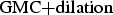 $\hbox{GMC}{+}\hbox{dilation}$, $\hbox{GMC}{+}\hbox{SP}$) mainly fail to segment MOs at a reasonable low FP detection rate (less than 80% TP detection rate at approximately 10% FP rate). It can be seen in Fig. 10(c) that our system including cluster filtering/mesh-based motion compensation and superpixel enhancement performs best with 92.9% TP detection rate at 3.5% FP detection rate. This even holds for the case when no temporally consistency of the superpixel segmentation is exploited (operating point SWW=1). For a SWW=3 we reach a TP detection rate of 96.4% at a FP detection rate of 6.2%.
B) Coding results and image quality evaluation
We used a modified x264 (v0.78) [50] AVC-encoder [5] at High Profile (Level 4.0) – further on referred to as AVC-skip – as a reference video coder using a fixed quantization parameter (QP). x264 has a coding performance similar to the JM reference software [51,Reference Tourapis, Leontaris, Sühring and Sullivan52] at similar settings but is significantly faster due to software optimizations, e.g. its multi-threading capability. The QP setting itself influences the image quality of the ROI blocks and consequently the resulting image quality after the decoding.
According to informal subjective tests (ten persons, using Mean Opinion Scores, MOSs,  $0=\hbox{worst}$, 5=best), the perceived image quality after the video decoding and reconstruction remains very high over the entire image as expected. For the MOS evaluation, the original frame as recorded by the camera was used as the hidden reference and common AVC was used as a low-quality anchor. Using our proposed ROI detection and coding system with a modified HEVC video codec (“ROI HEVC”) instead of a common unmodified HEVC codec, the MOS values are significantly increased by 0.7 and 0.8 up to 3.6 and 3.8 for 300 and 500 kbit/s, respectively. As can be seen in the magnifications in Fig. 11, common AVC is not able to produce a high image quality for bit rates equal to or lower than 500 kbit/s (Fig. 11(d)). Especially for very low bit rates below 500 kbit/s, our ROI-based system (Fig. 11(e)) retains much more high-frequency details (e.g. at a bit rate of 150 kbit/s like shown) resulting in a perceptively higher image quality compared to HEVC (Fig. 11(f)). However, due to the GMC of the background, small discontinuities at non-planar structures reconstructed from different New Areas might occur as can be seen, e.g. in Fig. 9(b) at the gable or in Fig. 11(b) at the upper right house roof. Although our test sequences were recorded in hilly terrain, which violates the planarity assumption, we were always able to reliably estimate the global motion of the scene and thus to reconstruct the video sequences by means of GMC.
Subjective image quality comparison for different video codecs and different very low bit rates (350 m sequence, 150–500 kbit/s). (f) ROI HEVC is proposed. Best viewed in pdf. (a) Original frame (whole frame). (b) ROI HEVC en- and decoded (whole frame, 300 kbit/s). (c) Original. (d) AVC 500 kbit/s. (e) HEVC 150 kbit/s. (f) ROI HEVC 150 kbit/s.
For an objective evaluation, we compare the results of AVC-skip to our proposed HEVC-skip implementation based on HM 10.0 [Reference Kim, McCann, Sugimoto, Bross and Han53] – called HEVC-skip – at low delay- (LD), Low Delay-P- (LD-P), and random access- (RA) profile-based settings with modified maximum block sizes (Coding Tree Units, CTUs, formerly known as argest Coding Units, LCUs) of 16×16 or 64×64 and smallest block sizes of 4×4 each. The generated bit streams are decodable with the HEVC compliant reference decoder HM 16.2. Apart from a modified maximum block size (and the corresponding partition depth resulting in 4×4 blocks) we applied the settings defined in the default HM configuration files encoder_lowdelay_main.cfg, encoder_lowdelay_P_main.cfg and encoder_ randomaccess_main.cfg. Our configuration details are listed in Table 1. For the RA profile, an intra (I) frame period of 32 was selected, whereas for the LD-P (only using predicted (P) frames as inter frames) and LD (containing bi-predicted/B frames as inter frames) profile only the first frame of a sequence was encoded in intra mode.
Configuration settings of the HEVC encoder for Low Delay (LD), Low Delay-P (LD-P) and Random Access (RA), based on the common HM configuration files encoder_lowdelay_main.cfg, encoder_lowdelay_P_main.cfg and encoder_randomaccess_main.cfg.
However, since with the new area of each frame, which is often intra coded anyway, there is a kind of “rolling intra frame”. Thus, theoretically, there is no need for the transmission of any intra frame at all since the decoder just has to wait for the next intra blocks within the new areas in order to continue decoding. Consequently, the highly efficient LD profile might be a good choice for scenarios with a demand of highest coding performance.
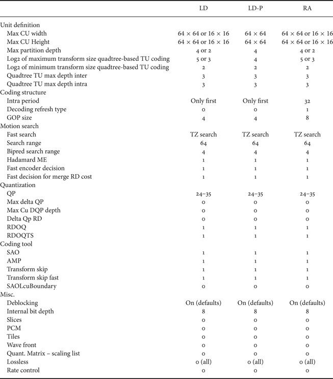
For our modified HM implementation (HEVC-skip) the skip mode was forced for non-ROI areas, whereas non-skip mode was forced for ROI areas (i.e. intra/any other inter mode than skip, PCM prohibited by configuration). Rate distortion (RD) plots are printed for different encoders (AVC, AVC-skip, HEVC, and HEVC-skip) and a maximum coding block size of 16×16 in Fig. 12. For the PSNR calculation we only considered luminance values within ROI areas. Similar evaluations can be found, e.g. in [Reference Grois and Hadar54,Reference Gorur and Amrutur55]. Errors introduced by GMC, e.g. caused by parallax, are assumed to be irrelevant as they influence the perceptional quality of the background only marginally and much less than a coarse quantization over the entire image. For the AVC-skip encoder at QP=33 – corresponding to a reconstructed Y-PSNR “video quality” of about 35 and 32 dB for the 350 m sequence and the 750 m sequence, respectively – we see a bit rate saving of about 80% compared to the unmodified non-ROI AVC coder which can be found in the same magnitude all over the RD plot. Similar findings hold true for HEVC-skip compared to the unmodified HEVC. The red arrows in the RD plots emphasize similar Y-PSNR quality levels comparing an unmodified HEVC encoder to the HEVC-skip system. Employing the HEVC-skip encoder, additional coding gains (Bjøntegaard delta, BD, BD-rate and BD-PSNR, cubic interpolation, QP range: 24–35 [Reference Bjøntegaard56,Reference Bjøntegaard57]) according to Table 2 can be achieved, e.g. for inter frames up to 33.2% for the high-resolution sequences and about 65% for the low-resolution sequence, corresponding to BD-PSNR gains of up to 1.7 dB (high-resolution sequences) and 3.46 dB (low-resolution sequence), respectively. Subjectively sufficient quality can be provided at a bit rate below 2 Mbit/s for each of these sequences, especially including the HDTV resolution sequences. It is noteworthy, that the actual coding gains of the inter predicted frames (which basically were examined and improved in this work) is about 28.8 and 33.2% for the 750 m sequence and the 350 m sequence, respectively. Whereas the latter sequence contains low noise and is easy to encode, for the former sequence neither an unmodified AVC nor the unmodified HEVC encoder will reach more than 35 dB Y-PSNR for bit rates smaller than 6500 kbit/s. Although the BD gains of the modified HM 10.0 encoder compared to the x264 encoder are smaller than reported in the literature [Reference Sullivan, Ohm, Han and Wiegand58] they approximately reflect the coding gains of 20–30% from an unmodified HEVC compared to an unmodified AVC.
RD diagrams for two test sequences from Test Set 1 (stars: AVC/AVC-skip, squares: HEVC/HEVC-skip; black: common, unmodified encoders, green: RA-alike, blue: LD-alike, maximum block sizes: 16×16 each, minimum block size: 4×4 each), red arrows emphasize bit rate saving of HEVC-skip system compared to unmodified HEVC coding. (a) 750 m sequence. (b) 350 m sequence.
Bjøntegaard delta (BD, BD rate, cubic, QP range: 24–35 and BD-PSNR) [Reference Bjøntegaard56,Reference Bjøntegaard57] for Test Set 1, negative BD-rate numbers represent coding gains of the proposed HEVC-skip coding system over the AVC-skip ROI coding system. “All” represents total gains over the entire sequence, whereas “Inter only” represents BD gains only for inter predicted frames, based on 16×16 (CTU16) and 64×64 (CTU64) largest coding block size for HEVC.
For the very low resolution VIRAT test sequence we need a bit rate of less than 500 kbit/s with our system compared to 1760 and 1580 kbit/s (at approximately 40 dB) for AVC and HEVC encoding, respectively.
For a reasonable operation point at SWW=3 we reduce the bit rate for the transmission of detected MOs by more than 24% compared to a MO detector relying on GMC for full HDTV video sequences at 30 fps. Including New Areas, the bit rate decreases only by 4%.
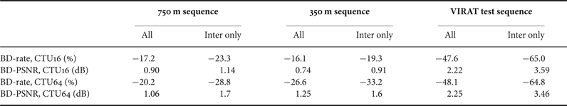
Coding results for the second test set containing no MOs (Fig. 8) using the modified HEVC video encoder (HM-skip) are provided in Table 3. Using the AVC-skip bit rates and the corresponding ROI Y-PSNR “qualities” as the anchor, we adjusted the QP for the competitors to match the quality as closely as possible. Finally, we interpolated the bit rate linearly in order to match the desired PSNR exactly. This linear interpolation is justified when looking at the RD curves in Fig. 12 at around 37–39 dB. Results are provided for the LD-P and LD profile at different block sizes. Bit rates for the LD-P profile are less than 10% lower for our test set than the achieved AVC bit rates, already considering the larger maximum coding block size of 64×64 for HEVC compared to 16×16 for AVC. In contrast to that for our skip-implementations the LD-P coding gains of more than 34% are comparably high. To achieve the best coding efficiency, we recommend the LD profile including bi-prediction for inter frames with a CTU size of 64×64. With this profile and the proposed HM-skip video encoder we are able to provide bit rates between 579 kbit/s (350 m sequence, 38.9 dB) and 872 kbit/s (500 m sequence, 37.2 dB), depending on the sequence characteristic, which is a bit rate saving of 35.1% compared to AVC-skip or 90.0% compared to common HEVC without any modifications. As already mentioned, the bit rate in a real system depends on the amount (and distribution) of ROIs to be encoded, which is typically 5–10% of a frame in our tests.
Coding gains (negative numbers) for Test Set 2 of proposed HEVC-based over AVC-based ROI coding system compared to the reference (Ref.) as marked in the table column by column. AVC and HEVC bit rates without ROI coding are additionally given (LD configurations-based with modified block-size according to the table, minimum MB/CU size=4×4).
C) Run-time considerations
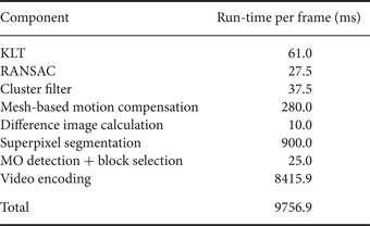
Since our proposed detection and coding system aims at real-time processing on-board an UAV, we consider the run-time for full HDTV resolution sequences recorded at 30 fps of our non-optimized C/\C++ and Matlab code on a typical modern desktop PC with an Intel Core i7-3770K CPU at a clock rate of 3.5 GHz running Linux. Except for parts of the superpixel segmentation all run-times are measured in single-thread processing, albeit parallelization of the components is able to decrease the run-time significantly. No hardware acceleration like GPU processing was applied yet.
The run-times for each component are listed in Table 4. It is obvious that the HEVC-skip video encoder consumes by far most of the time. Our experiments were carried out using a modified version of the reference software HM, which is used in the standardization process. A hardware HEVC encoder will even be capable of real-time processing of full HDTV bit streams at low power consumption and low cost.
Run-times per frame, non-optimized components written in C/C++, single thread execution on CPU (no GPU or other hardware acceleration), PC with an Intel Core i7-3770K CPU, clock rate of 3.5 GHz.
The Matlab-based superpixel segmentation consumes second-most of the run-time in the entire processing chain. Our Matlab implementation can segment a full HDTV resolution image into 1000 superpixels on our PC in about 900 ms. In [Reference Ren and Reid59] a much faster \C++ implementation was proposed which could be additionally sped-up by employing the GPU (using the NVIDIA CUDA framework and a NVIDIA GTX460 graphic card) by a factor of 20 compared to the sequential algorithm run on an Intel Core i7-2600 (3.6 GHz) CPU. Aiming at a real-time application, we also prepare an optimized C/\C++ implementation.
The third most computational burden is generated by the mesh-based motion compensation which can be easily parallelized on a triangle basis. Consequently, it can be realized in real-time on a (small) GPU.
The OpenCV [Reference Bradski60] KLT implementation as the fourth most consumer of run-time is able to process full HDTV content by tracking 3000 features as a maximum in a single thread at about 16 fps which means two CPU cores can easily process the video sequence for 30 fps sequences in real-time. More efficient KLT implementations like proposed in [Reference Mainali, Yang, Lafruit, Van Gool and Lauwereins61] might reach an even higher computational efficiency and thus shorter run-time.
Our cluster filter can process HDTV video sequences in (nearly) real-time. Whereas the run-time of RANSAC depends on the percentage of outliers and the number of iterations until the consensus is reached [Reference Chum and Matas62], it only consumes about 2.8% of the entire processing time in our tests and thus is real-time capable. The run-times of the remaining components, like the new area calculation based on the projective transformation parameters, are negligible in the entire processing chain.
For the proposed system we need a total run-time of nearly 10 s for the processing of each frame in full HDTV resolution on a single CPU core which equals a processing with about 0.1 fps. Assuming the usage of an HEVC IP core and the sped-up superpixels we should be able to already process at least 2 fps in software. Further algorithmic optimizations might include the usage of the sparse optical flow from KLT as well for the superpixel segmentation and the usage of background feature points for global motion estimation directly from the cluster filter while omitting RANSAC completely (which is a valid simplification for predominantly planar scenes). Taking into account the above software optimizations and the usage of parallel processing or even dedicated hardware like FPGAs or HEVC encoders, our proposed system can easily become real-time capable. Since power consumption and form factor restrictions apply on-board an UAV, the usage of dedicated hardware is advisable anyway.
VI. CONCLUSIONS
We present an aerial surveillance video coding system which can provide very low bit rates maintaining full image quality over the entire image. GMC is employed to reconstruct the background at the decoder side from already transmitted images. New areas contained in the current but not in the previous frame as well as MOs and previously covered background are transmitted. In order to limit the bit rate, it is crucial – especially for surveillance applications – to accurately detect new area and MOs. Therefore, non-moving regions falsely detected as moving have to be avoided to keep the bit rate as low as possible.
To decrease the FP detection rate we propose to replace the GMC by a mesh-based locally adaptive multiplanar approach within the MO detector. The mesh-based approach is capable of modeling distinct 3D structures more precisely. A cluster filter is introduced to distinguish between background motion and MOs based on an optical flow analysis. The reduced model aberrations lead to a decreased FP detection rate.
Since the MO detector is not able to accurately detect the shapes of MOs leading to reconstruction errors when not entire MOs are transmitted, we use an independently calculated, context-adaptive, TCS segmentation to increase the TP detection rate of the system.
Combining the superpixel segmentation and the mesh-based motion compensation, we are able to achieve a FP detection rate of only 1.8% while simultaneously increasing the TP detection rate to 97.9% (for a reasonable operating point) for challenging sequences. For the interlaced, low-resolution test sequence from the publicly available VIRAT data set we are able to detect 96.4% TPs at a FP detection rate of 6.2%.
Our final contribution is the integration of a modified HEVC encoder (employing the skip-mode by external control) into the coding system. In order to make the entire processing chain real-time capable for on-board usage at small and mid-size UAVs, optimized and hardware-accelerated algorithms are in preparation. Compared to a similarly modified AVC video encoder we gain an additional 30% (BD rate) or an equivalent of 1.65 dB (BD PSNR) for inter frames with the proposed HEVC-skip encoder for high-quality HDTV resolution aerial sequences (30 fps) and even more for lower resolution sequences. Typical aerial sequences containing MOs can be encoded at bit rates far below 2 Mbit/s. Compared to an unmodified HEVC encoder, we achieve a much higher image quality for very low bit rates (150–500 kbit/s).
Holger Meuel Holger Meuel studied Electrical Engineering at the Technische Universität (TU) Braunschweig with a focus on signal processing and communication techniques. He received his Dipl.-Ing. degree from the “Institute for Communications Technology, Department of Electronic Media: System Theory and Technology” of the TU Braunschweig, Germany, in 2010. After graduation he joined the Institut für Informationsverarbeitung (TNT) of Leibniz Universität Hannover as a Research and Teaching Assistant. He became the senior engineer end of 2010. Holger attended several standardization meetings for the video coding standard High Efficiency Video Coding (HEVC) of the MPEG and VCEG Joint Collaborative Team on Video Coding (JCT-VC). In that context, he also dealt with radial camera lens distortion compensation, scalable video coding, and screen content coding. His research interests are video coding with special focus on low bit rate video coding for aerial surveillance applications. Currently he is working towards his Dr.-Ing. degree.
Marco Munderloh Marco Munderloh achieved his Dipl.-Ing. degree in Computer Engineering with an emphasis on multimedia information and communication systems from the Technical University of Ilmenau, Germany, in 2004. His diploma thesis at the Fraunhofer Institute for Digital Media Technology dealt with holographic sound reproduction, the so-called wave field synthesis (WFS) where he helds a patent. During his work at the Fraunhofer Institute he was involved in the development of the first WFS-enabled movie theater. At the Institut für Informationsverarbeitung of Leibniz Universität Hannover, Marco Munderloh wrote his thesis with a focus on motion detection in scenes with non-static cameras for aerial surveillance applications and received his Dr.-Ing. degree in 2015.
Matthias Reso Matthias Reso studied Information Technology with an emphasis on Communication Technology and Microelectronics, at the Universität Paderborn. He wrote his diploma thesis at the Fachgebiet Nachrichtentechnik about blind source separation and achieved his Dipl.-Ing. degree in December 2011. In January 2012, he joined the Institut für Informationsverarbeitung at the Leibniz Universität Hannover as a research assistant. Since then he is working towards his Dr.-Ing. degree. His research interests are image and video segmentation with an emphasis on the topic of temporally consistent superpixel segmentation.
Jörn Ostermann Jörn Ostermann studied Electrical Engineering and Communications Engineering at the University of Hannover and Imperial College London. He received Dipl.-Ing. and Dr.-Ing. from the University of Hannover in 1988 and 1994, respectively. In 1994, he joined AT&T Bell Labs. From 1996 to 2003 he was with AT&T Labs – Research. Since 2003 he is Full Professor and Head of the Institut für Informationsverarbeitung at the Leibniz Universität Hannover, Germany. Since 2008, Jörn is the Chair of the Requirements Group of MPEG (ISO/IEC JTC1 SC29 WG11). Jörn received several international awards and is a Fellow of the IEEE. He published more than 100 research papers and book chapters. He is coauthor of a graduate level text book on video communications. He holds more than 30 patents. His current research interests are video coding and streaming, computer vision, 3D modeling, face animation, and computer–human interfaces.


 Open access