1 Introduction
The transformation process of firn to ice is one of the most fundamental subjects in polar ice-sheet studies. A number of theories regarding the dry densification of firn have been proposed (Reference RobinRobin, 1958 Reference SchyttSchytt, 1958 Reference BaderBader, 1960, 1962 Reference Benson Benson, 1962 Anderson and Reference BensonBenson, 1963 Reference KojimaKojima, 1964 Reference GowGow, 1975). However, a comprehensive model including grain-settling, sublimation/condensation, volume/ surface diffusion, ice deformation and recrystallization processes has not been firmly established. The densification processes have also been studied empirically (Reference RobinRobin, 1958 Reference SchyttSchytt, 1958 Reference Herron and LangwayHerron and Langway, 1980 Reference LingLing, 1985 Reference Langway, Shoji, Mitani and ClausenLangway and others, 1993). Reference SchyttSchytt (1958) found an empirical relation between firn density and the weight of overlying snow. Reference Herron and LangwayHerron and Langway (1980) investigated the validity of Schytt,s equation using 17 depth-density profiles from Greenland and Antarctica. Reference Langway, Shoji, Mitani and ClausenLangway and others (1993) showed a simple relation between overburden pressure and firn density
This paper focuses on obtaining a simple equation fora relationship between overburden pressure and firndensity from the surface to the depth of pore close-off considering the studies by Reference SchyttSchytt (1958) and Langwayand others (1993).
2 Analytical Procedure
Instead of using the snow densification law (Reference BaderBader, 1960,1962), an assumption was made that snow behaves like aperfectly plastic material. That is, porosity, s(= (ρi - ρ)/ ρi) is determined only by overburden pressure, P, at each depth level. ρis the firn density and ρi is the bubble-free ice density at -20°C (0.919.Mgm-3). When the pressure P increases to P +dP, s decreases to s-ds. Thereduction ratio of porosity, -ds/s was assumed toincrease proportionally to the increasing ratio of pressure, dP/P and the mth of power of s as follows:
where C and mare constants.
We obtained the following equations by integrating Equation (1):
where C1, C2, C3and C4 are constants.
Another equation was obtained by assuming that the reduction ratio of porosity, -ds/s increases proportionallytothe increment of pressure, dP, and the nth power of s as follows:
where D and n are constants.
Thus, we obtained the following equations:
where D1, D2, D3and D4are constants.
Recently, Reference Langway, Shoji, Mitani and ClausenLangway and others (1993) showed a linearrelation between (ρi-ρ)2and In(P) from the surface to.the depth of pare close-off for three sites in Greenland andAntarctica. If we rewrite the expression(ρi-ρ)2of Langway and others (1993) to ((ρi-ρ)/ρi)2, the relation is expressed as follows:
where E1 and E2are constants.
This equation is identical with Equation (2) with m=-2.
On the other hand, Reference SchyttSchytt (1958) proposed the following relation between firn density (ρ) and depth from the surface (h) far the Maudheim Ice core,Antarctica:
This equation is identical with Equation (4) with n = 0.
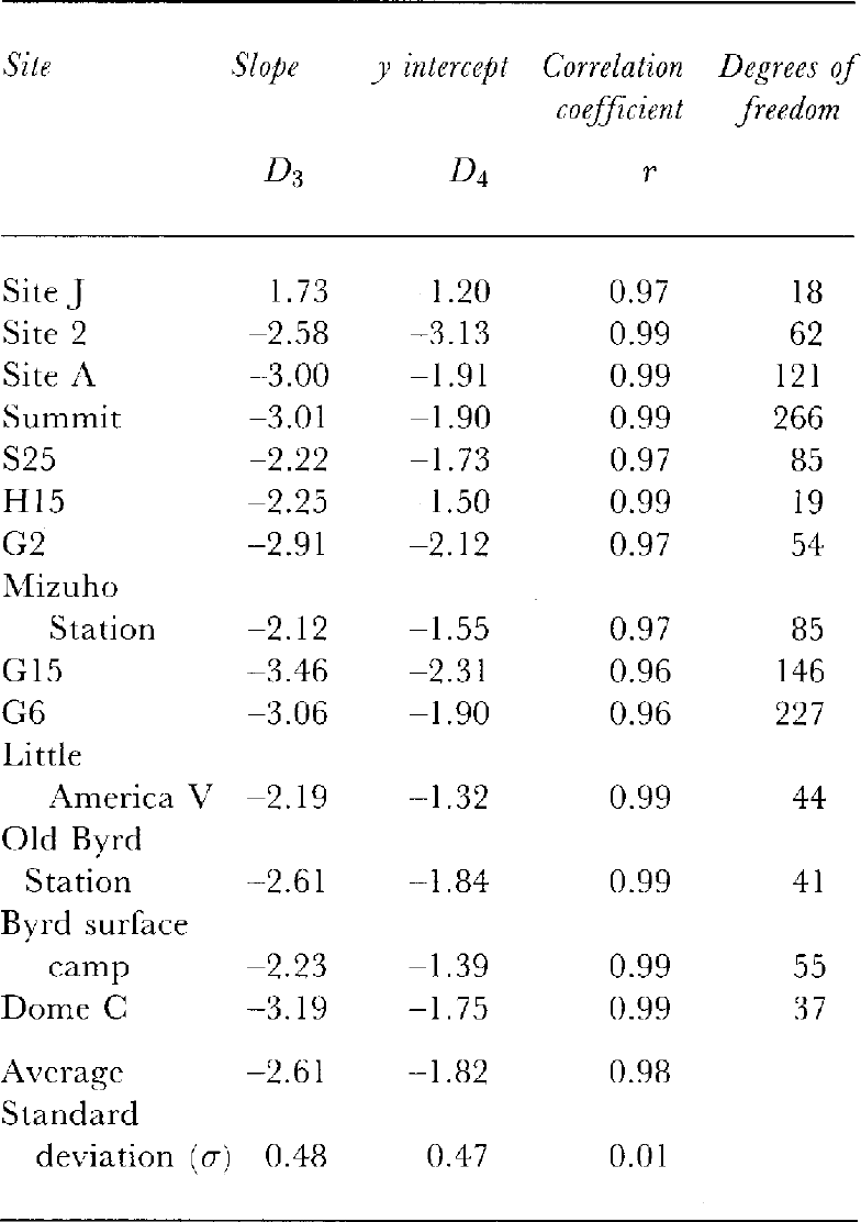
3 Results
Depth-density information was obtained from 14 sites in Greenland and Antarctica as shown in Table 1. The 10m depth firn temperatures of the borehole range from-54.3° to -16.4°C and annual accumulation rates rangefrom 0.034 to 0.39 m year 1 in water equivalent. Thedata scatters in bulk-density values are generally ±0.005 Mgm-3 for those from Summit, S25, H15, S25, G15, G6,Byrd surface camp and Dome C. On the other hand, thedata scatters for siteJ, site 2, site A, G2, Mizuho, LittleAmerica V and Old Byrd Station are within ±0.003 Mgm-3, since the densities were determined more precisely by a volumetric method. The reliabilityof 10 m depth temperatures is generally ±0.1°C or better.
A trial was made to find the most satisfactory valuesfor m and n in Equations (1) and (4) using the above depth-density profiles. Depth-density values from thesurface to the depth at which the density is 0.80 Mg m 3are used for the correlation-coefficient analysis.
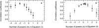
Figure la shows the results of the linearity test forEquation (1) using different values of m. It is clear that correlation coefficients take the highest values around m = -2 (r = 0.98). Figure 2b shows the results for Equation (4) using different values of n. It was found that the correlation coefficients take the highest value from n = -1 to + 1 (r = 0.97 at n = 1; r = 0.98 al n = 0;r = 0.95 at n = 1). Thus, we obtain the followingequations, which are identical with Equations (7) and (8):
where C1, C2, D3and D4are constants.
The relation between values of powers and correlation coefficients with their standard deviations. Figure 1a shows the results for m in Equation (1) and Figure 1b for n in Equation (4).

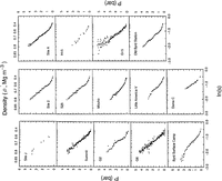
Relations between ln(P) and s2for 14 sites in Greenland and Antarctica. P is an overburden pressure and s is the porosity of firn, where s =(ρi-ρ)/ρi.ρi is the bubble-free ice density and ρ is the firn density.
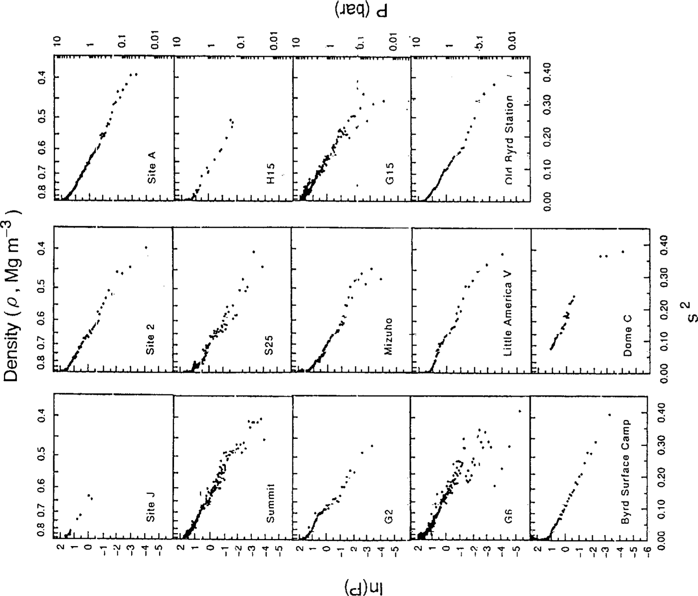
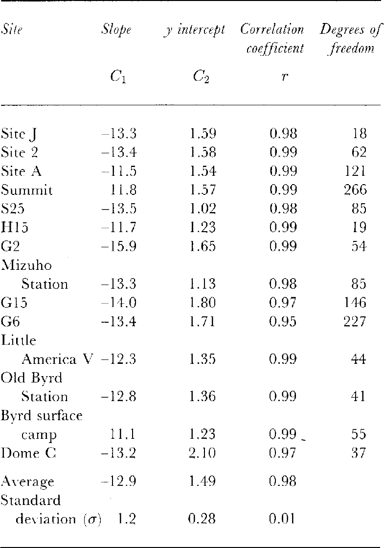
Figure 2 shows the relation between ln(P) and s2 for the 14 ice cores from Greenland and Antarctica. It is seenthat ln(P) and s2 have excellent linear correlation. Correlation coefficients, linear slopes (C1),Y intercepts(C2) and degrees of freedom are summarized in Table 2. The lowest correlation coefficient at G6 is due to datavariations in the surface-firn densities.
Figure 3 shows the relation between P and In(s) forthe 14 ice cores. It seems that most of the overburdenpressurecurves have a bend around a density of 0.50–0.60 Mg m-3. The linear-correlation analysis is summarizedin Table 3. The mean correlation coefficient forEquation (10), as shown in Figure 3(r = 0.98), is thesame as the mean correlation coefficients obtained for Equation (9) as shown in Figure 2 (r = 0.98).
Relations between P and In(.s) for 14 sites in Greenland and Antarctica

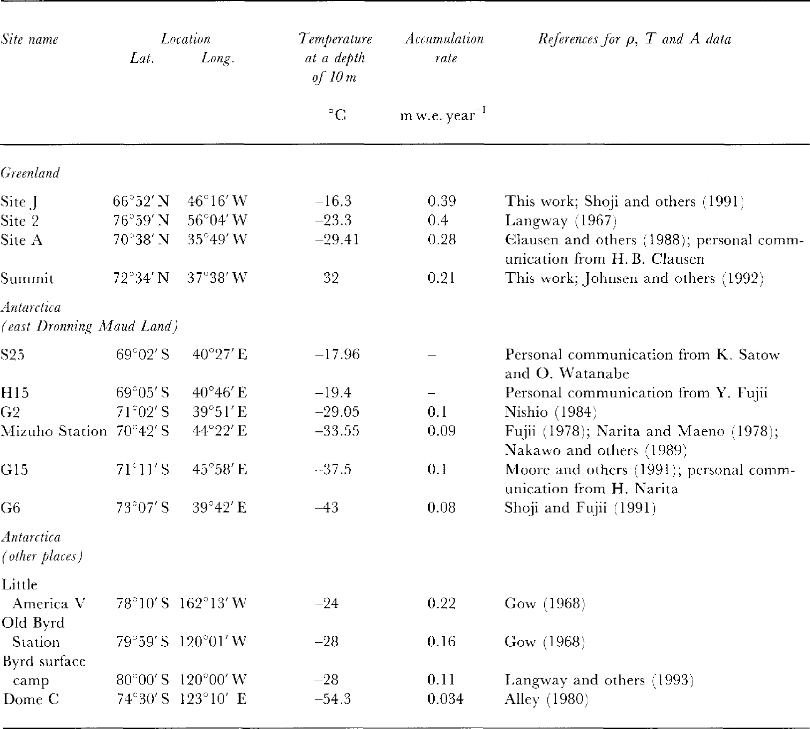
Glaciological data and references for Greenland and Antarctic ice cores
4 Discussion
4.1 The relation between ln(P) and s2
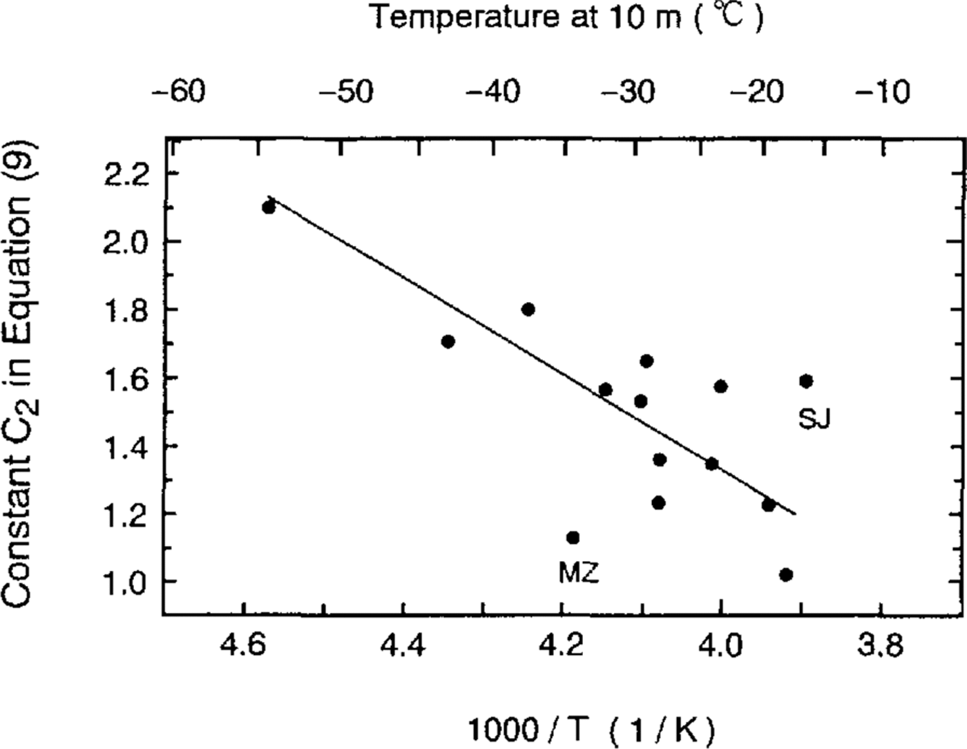
The slope and y intercept for each site were investigated tofind the dependence on 10m depth firn temperature and/orannual accumulation rate. It was found that the y intercepts, C2, are well correlated with 10 m firn temperatures(r = 0.69) as shown in Figure 4. This is the onlymeaningful correlation. It is clear that the y intercepts of siteJ (SJ) and Mizuho (MZ) are shifted from other data. Thecorrelation coefficient without the above two sites is as highas 0.88. With this temperature-dependence of y interceptsfor 12 data points, we obtain the following equation:
where T is the 10 m depth firn temperature in K, P is anoverburden pressure in bar, ρ is the firn density in Mg m 3 and ρi is the bubble-free ice density at -20°C(0.919Mgm 3).
Temperature-dependence of the y intercepts In Equation (9). SJ and MZ refer to ice coresfrom site J and Mizuho, respectively.
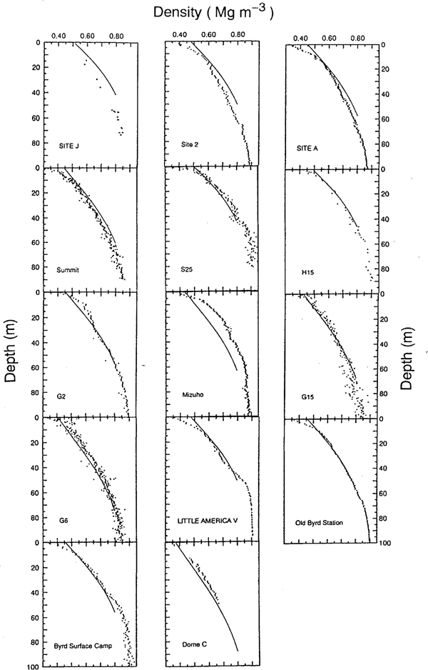
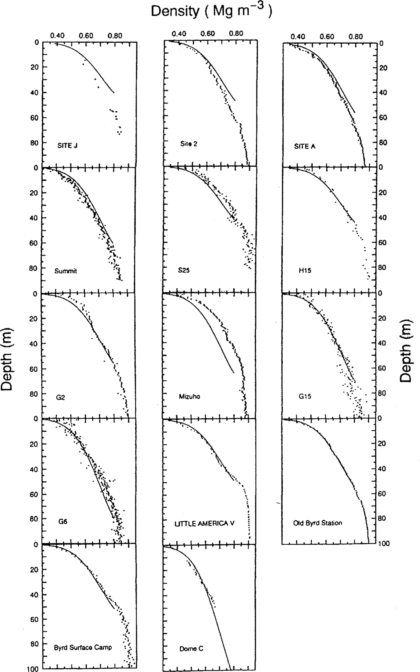
Comparisons of measured and calculated densityprofiles with Equation (11) are shown in Figure 5. It isseen that the site J and Mizuho ice-core data are shiftedsignificantly from the curves calculated from Equation(11). Site J is located in a percolation zone of theGreenland ice sheet Reference Watanabe and Fujii(Watanabe and Fujii, 1989) and the core contains 16.1% by volume of melt features (paper in preparation by Kameda and others).
Comparisons between measured density values (dots) and calculated profiles (lines). The calculated profiles areobtained from Equation (11).
Thus, refrozenwater around the grains can strengthen the grain bondingwhich may result in a delay in grain settling in the upper firn. On the other hand, Mizuho Station is located in acharacteristic area where an hiatus in snow deposition hasbeen studied Reference Watanabe, Kato and Satow(Watanabe and others, 1978). Katabaticwinds produce denser snow/firn layers at the surfacearound this area. This may cause a higher density valuefor the Mizuho ice core.
Standard deviations of measured densities from the calculated densities in 14 ice cores arc 0.02 Mg m-3 onaverage (i.e. 3.2% accuracy). The standard deviations inthe site J and Mizuho ice cores are 0.05 Mg m-3 and0.06 Mg m-3, respectively. These disagreements aremainly from C2 values at site J and Mizuho. That is,the agreement could be improved considerably, if theinitial density value is adopted instead of T in Equation (11) for each site.
Slopes, y intercepts, correlation coefficients and degrees of freedom for the relation in Equation (9)
Slopes, y intercepts, correlation coefficients and degrees freedom for the relation in Equation (10)
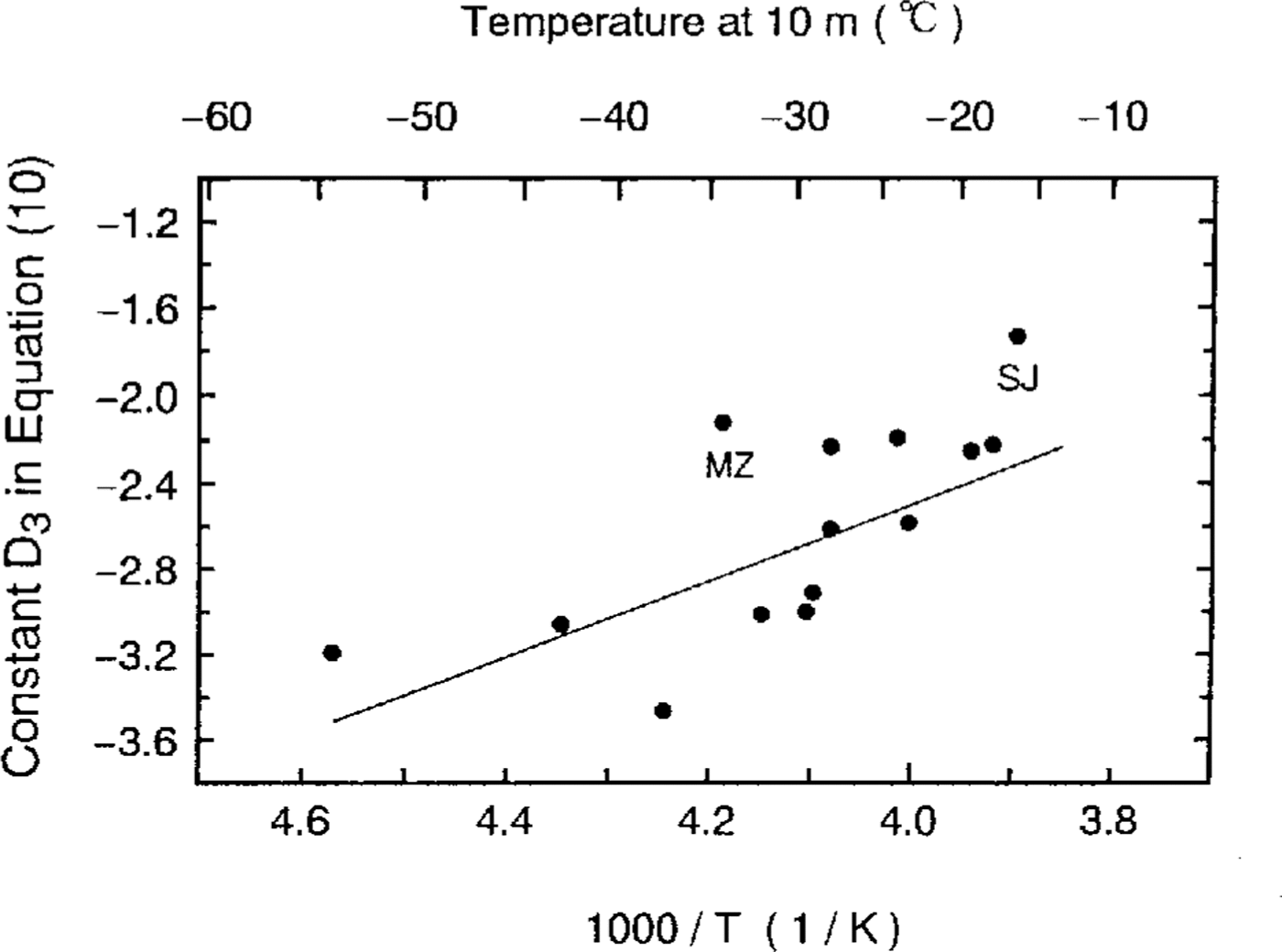
4.2 The relation between P and In(s)
The slopes and y intercepts were investigated to find thedependencies on the 10m depth firn temperatures and/orannual accumulation rates. It was found that the slopes,D3, are well. correlated with 10m firn temperatures(r = 0.72) as shown in Figure 6. For the same reasons as above, the values at site J and Mizuho could be deletedfrom Figure 6. The correlation coefficient between theslopes and the 10m depth firn temperatures has a slightlyhigher value of r = 0.76 if site J and Mizuho values are excluded. Using this temperature-dependence, we obtainthe following equation:
where T, P, ρandρi are the same as in Equation (11).
Temperature-dependence of the slopes in Equation(10). SJ and MZ refer to ice cores from site J and Mizuho, respectively.
Comparisons of measured and calculated densityvalues using Equation (12) are shown in Figure 7.Again, it is seen that site J and Mizuho ice-core datahave significant shifts from the curves calculated from Equation (12). Average differences between the measuredand calculated densities in 14 ice cores are 0.03 Mg m-3(i.e. 4.7% accuracy). The average differences betweenmeasured and calculated values for site J and Mizuho icecores are both 0.06 Mg m-3, which is approximately thesame magnitude as for the case using Equation (II).
Comparisons between measured density values (dots) and calculated profiles (lines). The calculated profiles areobtained from Equation (12).

Conclusion
These findings suggest that firn density can be determinedprimarily by overburden pressure; firn temperaturecontributes to a lesser degree, as expressed by Equations (11) and (12). That is, the validity of the equationproposed suggests that overburden pressure is the mostdominant factor in the densification process. Apparently,age-dependency is not as strong as expected previously for sites in a percolation zone or hiatus-observed area,each initial density at the surface should be taken intoaccount for a better fit with the measured density data.
Acknowledgements
We should like to thank Drs Y. Fujii, H. Narita, F. Nishioand K. Satow for providing unpublished depth-densitydata. The recovery of site J and Summit ice cores wassupported by a grant-in-aid for International ScientificResearch from the Japanese Ministry of Education, Science and Culture. We acknowledge logistic supportfrom GRIP members at Summit, Greenland. Ice cores from east Dronning Maud Land, Antarctica, wererecovered by the 23rd, 24th, 25th, 26th, 27th and 32ndJapanese Antarctic Research Expeditions.