


1. Introduction
The more than a century old study of drops impacting on solid and liquid surfaces has always been guided by the available imaging techniques, starting from spark imprinted sketches, to the first photographs of crown splashing captured by Worthington (Worthington & Cole Reference Worthington and Cole1897). The iconic milk-drop coronet was created by Edgerton (Reference Edgerton1977) using microsecond stroboscopic imaging from successive drops dripping onto the thin film deposited by the previous ones. High-speed video cameras have in the last two decades reached sub-microsecond resolution, allowing time-resolved study of the finest details of drop impact splashing even for high impact velocities (Thoroddsen, Etoh & Takehara Reference Thoroddsen, Etoh and Takehara2008). Besides the aesthetic fascination for this multiphase flow phenomenon (Peregrine Reference Peregrine1981), the details are important in a myriad of applications, such as injection sprays in internal combustion engines (Panão & Moreira Reference Panão and Moreira2005), as well as cleaning, coating (Bartolo, Josserand & Bonn Reference Bartolo, Josserand and Bonn2006) and cooling in electronics (Pasandideh-Fard et al. Reference Pasandideh-Fard, Aziz, Chandra and Mostaghimi2001). Fine splashed droplets also contribute to the formation of cloud condensation nuclei influencing climate (Veron Reference Veron2015). Furthermore, airborne droplets from sneezing are critical for spreading disease in plants, animals and humans (Bourouiba, Dehandschoewercker & Bush Reference Bourouiba, Dehandschoewercker and Bush2014). Even the habitability of exoplanets could be affected by exotic rain and aerosol formation by splashing (Loftus & Wordsworth Reference Loftus and Wordsworth2021).
Ejecta sheets produced by drop impacts emerge out of the neck connecting the drop to the pool at their initial contact. They were discovered in the numerical simulations of Weiss & Yarin (Reference Weiss and Yarin1999) who suggested their immediate breakdown, while the first images by Thoroddsen (Reference Thoroddsen2002) showed that they remain intact for viscosities moderately larger than that of water. These ejecta sheets are fundamentally different from the Peregrine sheet that forms later, when the drop penetrates the layer (Deegan, Brunet & Eggers Reference Deegan, Brunet and Eggers2007; Zhang et al. Reference Zhang, Toole, Fezzaa and Deegan2012a). The discovery of multiple sheets by an X-ray visualization method indicates the profound complexity of this process (Zhang et al. Reference Zhang, Toole, Fezzaa and Deegan2012b). For water drops, the ejecta sheet breaks up rapidly into small droplets. The early breakup of the sheet was shown to be caused by vortex shedding from the base of the ejecta (Thoraval et al. Reference Thoraval, Takehara, Etoh, Popinet, Ray, Josserand, Zaleski and Thoroddsen2012). However, for moderate viscosity, the sheet remains intact and tends to bend down towards the pool surface, to entrap a toroidal bubble (Thoroddsen Reference Thoroddsen2002). Besides the prompt splash (Thoroddsen Reference Thoroddsen2002; Josserand & Zaleski Reference Josserand and Zaleski2003), the tip of the ejecta can disintegrate into microdroplets by a slingshot mechanism under conditions where the sheet bends down and ruptures where it hits the liquid layer (Thoroddsen et al. Reference Thoroddsen, Thoraval, Takehara and Etoh2011; Moore, Whiteley & Oliver Reference Moore, Whiteley and Oliver2018). More splashing mechanisms have been proposed to drive multiple instabilities and nonlinearity of the crown breakup (Yarin & Weiss Reference Yarin and Weiss1995; Krechetnikov & Homsy Reference Krechetnikov and Homsy2009; Bisighini et al. Reference Bisighini, Cossali, Tropea and Roisman2010; Zhang et al. Reference Zhang, Brunet, Eggers and Deegan2010; Wang et al. Reference Wang, Dandekar, Bustos, Poulain and Bourouiba2018; Stumpf et al. Reference Stumpf, Roisman, Yarin and Tropea2023). Splashing thresholds have been obtained (Vander Wal, Berger & Mozes Reference Vander Wal, Berger and Mozes2006; Kittel, Roisman & Tropea Reference Kittel, Roisman and Tropea2018) in forms that are reminiscent of the drop impact on a solid surface (Stow & Hadfield Reference Stow and Hadfield1981; Mundo, Sommerfeld & Tropea Reference Mundo, Sommerfeld and Tropea1995). The entrapped air torus is also crucial to the ejecta size and stability (Zhang et al. Reference Zhang, Toole, Fezzaa and Deegan2012b; Josserand, Ray & Zaleski Reference Josserand, Ray and Zaleski2016).
Our study is meant to elucidate the dynamics of the ejecta sheets, by coupling their morphology with the forces driving their motion. The ejecta evolution and later crown splashing are obtained by two separate high-speed cameras, using two magnifications. Figure 1 shows simultaneous images taken at widely different magnifications. The outcomes of our ejecta are more perplexing than the recent study by Marcotte et al. (Reference Marcotte, Michon, Séon and Josserand2019), as we scan a much larger parameter space. Fudge et al. (Reference Fudge, Cimpeanu, Antkowiak, Castrejón-Pita and Castrejón-Pita2023) have also looked at ejecta formation and splashing, using immiscible liquids, over a range of viscosities in the pool.
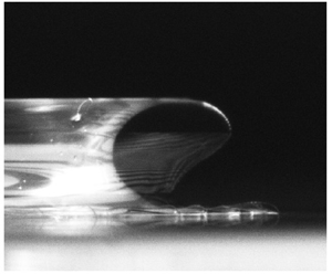
(a) The emergence, upward bending of the tip and breakdown of the ejecta sheet for a  $\mu _d=141$ cP drop impacting onto a lower viscosity film of $\mu _p=79$ cP liquid ( $\beta = \mu _f/\mu _d=0.56$), under ambient pressure 800 mbar. Here, $U=10.4$ m s $^{-1}$, $D_H=5.85$ mm and $R_b=7.8$ mm, giving $We=31\,700$ and $Re=1410$. The sequence of frames shows the formation of an axisymmetric duck shape ejecta profile (see supplementary movie 1 available at https://doi.org/10.1017/jfm.2023.1039). The times in $\mathrm {\mu }$s are relative to the first contact of the drop with the film surface. (b) Traces of the ejecta profiles, starting at $t=25\,\mathrm {\mu }$s, with 5.4 $\mathrm {\mu }$s intervals between profiles. (c) Stacked sections of video frames, from a second video camera, showing the overall view of the ejecta evolution following the early shapes in (a), traced from the left side. The times of the splashing shapes relative to first contact are 0.075, 0.908 and 5.86 ms. The drop in free-fall is also shown.

High impact velocities are attained by a 26 m long tube under reduced ambient pressures in which the drop falls freely. Engel (Reference Engel1966) constructed a similar device in 1966, but her measurements were limited by the high-frame-rate film cameras available at the time, and she studied only impacting water drops. More recently, the effective impact velocity has been increased greatly by an ingenious method, based on translating the substrate rapidly to hit the freely falling drop. The substrate is attached to a flywheel, allowing impacts on a dry surface at effective velocities of water drops up to 26 m s $^{-1}$, in Burzynski, Roisman & Bansmer (Reference Burzynski, Roisman and Bansmer2020). Burzynski & Bansmer (Reference Burzynski and Bansmer2018) developed a system with a thin flowing film on the substrate, reaching the impact of a 3 mm water drop at 10.5 m s $^{-1}$ on a 140 $\mathrm {\mu }$m film. Dual-frame particle image velocimetry cameras were used for high-resolution images of the splash, to get the size and velocity of spray droplets down to 5 $\mathrm {\mu }$m. This also allowed determination of the total ejected splash volume. In a related idea, Ashida et al. (Reference Ashida, Watanabe, Kobayashi, Fujii and Sanada2020) studied prompt splashing on a dry surface, by impact accelerated substrate moving upwards to meet the freely falling drop, producing effective impact velocities up to 33 m s $^{-1}$. The plate was accelerated by the impact of an iron bullet driven by a coilgun. Earlier, Mehdizadeh, Chandra & Mostaghimi (Reference Mehdizadeh, Chandra and Mostaghimi2004) used a horizontal flywheel at velocity 40 m s $^{-1}$, but showing only snapshot images of the splashing on dry surfaces, to study finger formation. Gloerfeld et al. (Reference Gloerfeld, Roisman, Hussong and Tropea2021) have taken a different approach, with a co-axial air stream inside a vertical wind tunnel, thereby accelerating small water droplets to impact velocities up to 13 m s $^{-1}$ onto a solid surface. Keep in mind that these methods will not work for drop impacts on stationary pools.
Theoretical studies of ejecta started using potential theory. The early-time structure of such ejecta is found to follow the Wagner theory, which does not consider the air flow (Wagner Reference Wagner1932; Howison et al. Reference Howison, Ockendon, Oliver and Purvis2005), while Coppola, Rocco & de Luca (Reference Coppola, Rocco and de Luca2011) and Cimpeanu & Moore (Reference Cimpeanu and Moore2018) included numerical simulations with the gas.
Our imaging shows the importance of the air resistance on the ejecta-sheet bending and shape evolution, but also the crucial role of confinement of the air volume between the sheet and the boundaries, leading to net suction pressure that dominates the bending and sheet breakup. The air resistance is small while the ejecta sheet translates horizontally tangent to its length. On the other hand, when its tip starts to bend, the resistance to motion normal to it increases greatly, leading to rapid catastrophic bending. We also show conclusively that the thickness of the ejecta becomes sub-micron along its leading section, where the azimuthal stretching is most pronounced.
2. Experimental set-up
Herein, we study drop impacts under novel parameter regimes, where the ejecta sheet remains intact during the earliest phase of the impact. This is accomplished by using very large impact velocities in the 26 m long vacuum tube, shown schematically in figure 2. The impact of water drops at these high velocities leads to immediate breakup of the ejecta into fine droplets at first emergence (Thoroddsen Reference Thoroddsen2002) owing to the large Reynolds number. To overcome this, we increase the liquid viscosity by using various mixtures of water/glycerol in the drop and the liquid film. The viscosity of the mixtures is varied over a large range from 20 to 1080 cP while introducing only small variations in density and surface tension, as listed in Table S1 of the supplementary material. The three most pertinent dimensionless numbers characterizing the impacts are the Weber number  $We$, the Reynolds number $Re$, and the viscosity ratio between drop and pool $\beta$, which are defined below with their ranges of values:
 \begin{align} We = \frac{\rho_d U^2 D}{\sigma_d} = 22\,000\unicode{x2013}69\,000,\quad Re = \frac{\rho_d U D}{\mu_d} = 155\unicode{x2013}4366,\quad \beta = \frac{\mu_f}{\mu_d} = 0.14\unicode{x2013}7.6, \end{align}
where  $\rho _d$, $\sigma _d$, $\mu _d$ are the drop density, surface tension and dynamic viscosity, and $D$ is the effective drop diameter based on the bottom curvature of the drop, i.e. $D=2R_b$. We use this length scale as the emergence and evolution of the ejecta sheet occurs before the drop has penetrated to a one radius depth, and the local impulsive dynamical pressure will arise from the local geometry (Philippi, Lagrée & Antkowiak Reference Philippi, Lagrée and Antkowiak2016). We have used this length for successful scaling for early impacts on both solid and liquid surfaces, in Li & Thoroddsen (Reference Li and Thoroddsen2015) and Li et al. (Reference Li, Thoraval, Marston and Thoroddsen2018), respectively. The $f$ and $d$ subscripts refer to the film/pool and drop properties, respectively. Note that both the impact velocity $U$ and bottom radius of curvature $R_b$ depend on the ambient pressure $P_a$ inside the vacuum tube.
The overall structure of the 26 m long vacuum tube, built in a safety stairwell, with the two high-speed video camera views. Inset 1 shows the motorized cup that blocks the drop release during the air evacuation from the tube. The rotating tray can be seen inside the bottom box. It can support 8 microscope slides to increase the number of trials for each evacuation cycle. The two cameras were used to capture the impact, one assigned for observing the ejecta with larger magnification and higher frame rates, while the second one captures the overall view of the impact crown. (Drawn by Xavier Pita, scientific illustrator at King Abdullah University of Science and Technology (KAUST).)

2.1. The long vacuum tube
Figure 2 sketches the experimental set-up used in the work. It consists of a custom-built 26 m long vacuum tube, built inside the centre gap in a five-storey safety stairwell. The width of this gap limited the tube size to about 20 cm outer diameter. The terminal velocity of a free-falling millimetric raindrop at atmospheric pressure is  ${\simeq }10$ m s $^{-1}$, which is reached when gravity is balanced by the drag force from the surrounding air. By reducing the atmospheric pressure, the drop can attain a higher velocity during the free-fall and remain more spherical. Herein, we built a 26 m long vacuum tube, connecting to top and bottom vacuum chambers, as shown in figure 2, which is mounted inside a five-floor safety stairwell. The tube is glued together from 6 m sections of four-inch inner diameter PVC pipe, while the chambers are acrylic. The drop is generated and released from a metallic bronze nozzle 5 mm in diameter, with liquid supplied by a syringe pump in the upper chamber. During evacuation of the system, there is not enough back pressure to hold liquid inside the dripping tube, and any air bubbles present will expand against the decreasing ambient pressure and push unwanted droplets out of the nozzle. Therefore, a glass cup attached to an electrically driven rotary motor is positioned under the nozzle to avoid unnecessary wetting of the substrate, before the release of the actual drop. In free-fall, the drop acceleration in the long tube is slowed by air resistance, over a range of reduced ambient pressures, thereby giving impact velocities 9–22 m s $^{-1}$.
The drop impacts onto a liquid film, fully wetting a microscope glass slide inside the bottom chamber. The film is spread on the clean slide by depositing a fixed amount of liquid from a syringe. The thickness is varied within 1–3 mm for different viscosities, but remains effectively thick relative to the initial ejecta dynamics (Thoroddsen Reference Thoroddsen2002; Thoraval et al. Reference Thoraval, Takehara, Etoh, Popinet, Ray, Josserand, Zaleski and Thoroddsen2012). The bottom rotating tray has multiple slots for fresh microscope slides. When  $\beta = 1$, this allows us to perform multiple realizations at the same air pressure, without opening the chamber. When drop and pool are of different liquids, to prevent any contamination from splashing, we needed to open the chamber between each impact. The internal pressure is controlled by a vacuum pump and a pressure gauge at the top chamber. During the experiment, two researchers must collaborate. One, on the top floor, controls the pumps to reduce the chamber pressure inside the facility, and releases a drop in the top chamber, while the other changes the substrate, synchronizes the two cameras, and initializes the trigger to capture the splashing. The two communicate via wireless network.
We use water/glycerol mixtures to vary the liquid viscosity, as shown in Table S1 of the supplementary material. The mixture is composed of purified deionized water (Milli-Q) and glycerol from Fisher BioReagents $\unicode{x00AE}$.
At very high impact velocities, the ejecta forms within tens of microseconds after the drop touches the free surface, and the sheet evolves greatly within the first millisecond. The minimum length scale of the ejecta is its thickness, which is of the order of micrometres. Therefore, we use two high-speed video cameras (Phantom V2511) to observe simultaneously the ejecta evolution at different magnifications and frame rates. The close-up camera uses a long-distance microscope (Leica Z16 APO) with spatial resolution 32  $\mathrm {\mu }$m px $^{-1}$ and 360 000 fps at $640 \times 80$ px, while the overall view is captured using a Nikkor 105 mm lens with 75 $\mathrm {\mu }$m px $^{-1}$ resolution at 60 000 fps at $768 \times 480$ px. Typical video clips from both cameras are included in the supplementary material.
3. Results
Figure 1(a) shows the convoluted shape of the axisymmetric ejecta sheet occurring long before the rise of the Edgerton crown in figure 1(c). The ejecta evolution is controlled primarily by the air resistance, while viscous stress and surface tension also play a role, along with the initial impact conditions. The ejecta sheet (Thoroddsen Reference Thoroddsen2002) can be considered to be distinct from the later crown formation, which is thicker and rises near vertically to much larger heights; see figure 1(c). The bending of the ejecta is controlled by the angle of ejection of the initial straight tip of the ejecta. Figure 3 characterizes this initial ejection angle and bending. It shows clearly that the sheet bends upwards if the pool viscosity is lower than the drop viscosity. This initial bending direction is independent of the ambient air pressure, and the critical viscosity ratio between upwards or downwards bending is approximately unity (figure 3b). In other words, the sheet bends upwards for a lower-viscosity pool, i.e.  $\beta = \mu _p/\mu _d \le 1$. For equal viscosity, $\beta = 1$, both bending directions can occur, depending on the Reynolds number, with low $Re$ bending downwards (figure 3c).
Regime map showing the direction of ejecta bending, up (blue triangles) or down (red crosses). (a) Video frames showing how the ejecta sheet bends up (left-hand frame with blue arrow) or down (right-hand frame with red arrow). (b) Direction of ejecta bending for a range of different viscosity ratios and reduced ambient pressures. The dashed line indicates identical viscosities in drop and pool, i.e.  $\mu _f/\mu _d =1$. On this line, the bending direction depends on Reynolds number as shown in (c). (c) Map of the bending orientation based on $Re$ and pressure $P^*$ at $\mu _f/\mu _d =1$, which overlap in (b).

For the downwards bending of the ejecta, an elbow forms near the tip, which is pulled downwards and then impacts the pool (Thoroddsen Reference Thoroddsen2002). We propose a simple physical model to predict the motion of this elbow. The overall curved ejecta shape arises from the kinematics of the variable ejection velocity and ejection angle during the early contact of the drop with the pool, as modelled by Thoroddsen et al. (Reference Thoroddsen, Thoraval, Takehara and Etoh2011). The bending near the tip is assumed to be triggered by the air drag acting on the rapidly moving ejecta. When the sheet starts to bend towards the pool, an elbow is formed and air will be sucked underneath this elbow, as sketched in figure 4(a). The tip of the sheet has larger inertia via the thicker Taylor rim, generated by the pullback of the edge by surface tension. The difference in dynamic pressure on the two sides of the elbow is the driving force of this downward motion.
Elbow dynamics and shape of entrapped air torus. The mechanism of the bending of the ejecta elbow is found to be driven mainly by the pressure difference between the two sides, which is acquired by the Bernoulli suction pressure. (a) Sequence of frames showing the ejecta bending down, and a sketch of the elbow in the ejecta sheet being pulled down by the Bernoulli suction pressure from the fast air motions underneath it. (b) The volume of the enclosed air under the ejecta sheet versus time, before the elbow touches the surface. The volume growth rate is approximately constant during the short time when the elbow is pulled down, as is shown for different liquid combinations at various pressures. (c) Elbow height above the pool surface versus time. The black solid line is the numerical solution from (3.2), and the blue dashed line is the corresponding downward velocity of the elbow. The red stars are the experimental data. Viscosity of both liquid and film is 231 cP, and the ambient pressure is 402 mbar. (d–h) The mechanism of the ejecta deformation after the enclosure of the air torus. (d) Sequence of three video frames showing the ejecta torus deformation after the elbow touches the pool surface. The sketch below shows the enclosed air torus with the tongue pulled in near the pool surface. (e) The air volume inside the enclosed torus, measured from the video frames, assuming axisymmetry. The volume grows until it reaches a constant (blue circles) soon after it closes up. The volume is approximately 5 % larger than when the elbow first touches the pool. (f–h) The ejecta shape evolution from the kinematic model, showing the pulling in of the air pocket. The red, blue and green arrows in (f) show respectively the normal vector, the velocity and the acceleration from the applied pressure difference. The curves in (g,h) show the time evolution of the shape and are spaced by 0.5  $\mathrm {\mu }$s.

3.1. Ejecta elbow dynamics
The ejecta sheet begins to bend down towards the pool surface, forming an elbow a short time after its emergence (Thoroddsen Reference Thoroddsen2002). This bending behaviour is triggered by the air drag resisting its rapid radial motions and variable ejection angle, as in the kinematic model in Thoroddsen et al. (Reference Thoroddsen, Thoraval, Takehara and Etoh2011), as sketched in figure 4(a). The video clips show the elbow accelerate strongly down towards the pool surface. This acceleration is counterintuitive on the following grounds: first, gravity is too weak to drive any of these motions, and second, both surface tension and viscous stress in the sheet should provide an upward force at the elbow, where the curvature is largest in the axial plane. We are left with the following explanation. The rising ejecta sheet encloses a volume of air, bounded below it by the pool surface (see figure 4a). As the curved ejecta rises up and expands radially, the air volume under it grows, and additional air must therefore be sucked underneath the elbow. When the elbow approaches the pool, the gap width  $h$ reduces and the air speed increases, inducing a Bernoulli suction pressure, thereby pulling the elbow further down. Locally at the elbow, this pressure accelerates the liquid sheet towards the pool:
 \begin{equation} {-}M\,h(t)'' =
\frac{1}{2}\rho_{air}U_{air}^2
= \frac{1}{2}\rho_{air}
\left(\frac{Q}{h}\right)^2,\end{equation}
\begin{equation} {-}M\,h(t)'' =
\frac{1}{2}\rho_{air}U_{air}^2
= \frac{1}{2}\rho_{air}
\left(\frac{Q}{h}\right)^2,\end{equation}
where  $\rho _{air}$ is the density of the ambient air, $U_{air}$ is the suction velocity of the air through the gap $h$ below the ejecta elbow, $M$ is the mass of the section of the elbow, and $h(t)''$ is the resulting downward acceleration. Meanwhile, $U_{air}$ in (3.1) can be rewritten in terms of $h$ and the rate of change of the air volume under the ejecta, $Q = ({\rm d} Vol/{\rm d} t) / (2{\rm \pi} R_e)$, which drives air flow into the growing torus underneath the ejecta. The volume change of the torus can be integrated from the video frames, based on axisymmetry. Owing to the rapid downward movement, the radial position of the elbow $R_e$ is approximately constant. Figure 4(b) shows that $Q$ is also constant over the short time. This leads to a second-order ordinary differential equation describing the elbow dynamics:
 \begin{equation} h^2h'' = C_{\delta}, \end{equation}
where the constant is  $C_{\delta } = -\rho _{air} Q^2/(2 \rho _{d} \delta )$, and $\delta$, the sheet thickness, is the only unknown. Figure 4(c) shows the implicit numerical solution of (3.2), which agrees well with the experimental data using $\delta$ as a fitting parameter. The black solid line is achieved by choosing $\delta = 1.2\,\mathrm {\mu }$m in reasonable agreement with other estimates.
In the above case, as there is no film rupture or slingshot of a liquid edge, the ejecta sheet thickness cannot be obtained independently from applying the Taylor–Culick law directly, as was done in earlier related work (Thoroddsen et al. Reference Thoroddsen, Thoraval, Takehara and Etoh2011; Aljedaani et al. Reference Aljedaani, Wang, Jetly and Thoroddsen2018). Conceptually similar Bernoulli suction occurs during sphere impact onto deep pools, where the top of the crown is pulled together by air flow into the growing crater (Marston et al. Reference Marston, Truscott, Speirs, Mansoor and Thoroddsen2016).
3.2. The ejecta stretching and sheet thickness
The thickness profile along the arc length of the ejecta becomes important when deciding which part of it reacts most strongly to the air resistance. This becomes particularly important after the elbow touches the pool surface and suction pressure inside the enclosed air torus becomes dominant, as discussed below. The sheet thickness is determined by three main effects. The first is the initial thickness and velocity when it emerges from the neck region between the drop and pool. The initial velocity goes as  $U_j/U \propto Re^{1/2}$ (see figure 4a), while initial thickness scales with a viscous length scale, as $\delta (t) =\sqrt {\nu t}$, thereby thickening with time (Thoroddsen Reference Thoroddsen2002). The dependence of ejecta thickness on liquid viscosity has also been seen in the numerical simulations of Josserand & Zaleski (Reference Josserand and Zaleski2003) and Agbaglah & Deegan (Reference Agbaglah and Deegan2014). The X-ray imaging of Zhang et al. (Reference Zhang, Toole, Fezzaa and Deegan2012b) has shown directly the thickening of the ejecta with the impact Reynolds number. The second effect is the longitudinal stretching along its length, in the axial plane $(z,r)$, which arises directly from the reduction in the base ejection velocity with time $U_j(t)$ and its increased ejection angle (Thoraval et al. Reference Thoraval, Takehara, Etoh, Popinet, Ray, Josserand, Zaleski and Thoroddsen2012). The third effect is the azimuthal stretching, which occurs with the increased periphery when the ejecta sheet moves in the radial direction. The last of these three effects turns out to be by far the most significant. The relative importance of the three factors can be quantified using the kinematic model of Thoroddsen et al. (Reference Thoroddsen, Thoraval, Takehara and Etoh2011). Figure 5(b) shows a typical ejecta shape from this model, for $U_j/U= 14$, when the sphere has penetrated 20 % of its radius ( $\tau =tU/R=0.2$). The model, described in the supplementary material, shows that the largest stretching of the ejecta in the axial plane is near the tip, at up to a factor 2.5. The tip is where the ejection velocity is the largest and the direction of this ejection changes most rapidly. However, this stretching is dwarfed by the azimuthal stretching as the periphery of the sheet grows linearly with $r$. Typical ejecta emerges at $r/R_d \simeq 0.2$ and may touch the pool at value $r/R_d \sim 2$, thereby producing a tenfold stretching near the tip. Furthermore, the thickness of the ejecta as it emerges from the neck increases with time, owing to viscous effects. Here, we model this thickness at the base, as (Josserand & Zaleski Reference Josserand and Zaleski2003; Thoraval et al. Reference Thoraval, Takehara, Etoh, Popinet, Ray, Josserand, Zaleski and Thoroddsen2012)
 \begin{equation} \delta = \delta_o + \sqrt{\nu t}. \end{equation}
Finally, combining these three factors, we estimate the variation of the thickness of the ejecta sheet along its length, as shown in figure 5(c). This highlights the rapid thinning near the tip.
(a) The initial ejecta velocity  $U_j$ normalized by the drop impact velocity $U$ versus impact Reynolds number based on the bottom radius of curvature of the drop at impact, measured over a range of liquid viscosities, with drop and pool of the same liquid. The red dashed line has slope 0.18. (b) The axial stretching of the ejecta based on the simplified kinematic model from Thoroddsen et al. (Reference Thoroddsen, Thoraval, Takehara and Etoh2011). The black curve is the ejecta shape at $\tau =tU/R=0.2$, and the red curve shows the total axial in-plane stretching of the element since emergence from the drop-pool neck. (c) The corresponding thickness of the ejecta sheet, taking into account axial and azimuthal stretching and the initial ejected thickness in (3.3) with $\delta _o=15\,\mathrm {\mu }$m, based on the thinnest ejecta tip seen in Thoroddsen (Reference Thoroddsen2002).

3.3. Dynamics of the enclosed air torus
Once the elbow of the ejecta reaches the pool surface, it encloses an air torus and the subsequent evolution is influenced by the near incompressibility of the air within the torus, which imposes a controlling pressure difference between the inner and outer sides of the liquid sheet, to maintain approximately a constant volume. Measurements from the video frames show that the enclosed toroidal air volume increases by only approximately 5 % from that at the enclosure (figure 4e). This suggests an effective suction pressure difference  ${\rm \Delta} p$ restraining the torus from expanding much. However, as the thicker top section continues to move radially and rise, the compensating deformation must begin at the thinnest part of the ejecta closest to the pool surface, which is pulled back radially, as indicated by the white arrows in figure 6(a), for a typical case. The subsequent ejecta shape evolution is greatly affected, with a prominent pullback of an air pocket near the pool surface; see figure 4(d). This is where the sheet is thinnest, as explained in figure 5(c). See also figure 8(d) in Thoroddsen et al. (Reference Thoroddsen, Etoh and Takehara2008).
(a) A sequence of ejecta evolution of a 141 cP drop impacting on an identical liquid film, at  $P_a = 694$ mbar. As soon as the ejecta neck touches down, the bottom part of the sheet starts being pulled in by the suction pressure inside the enclosed torus, which is indicated by the arrows. This air tongue of the sheet is axisymmetric and visible from both sides. It pinches off to form an internal torus, which is pointed out by the white arrows. The top scale bar is 1 mm, and the bottom bar is 0.25 mm. Close-up traces in (b,c) show the tongue shapes spaced by $dt=5.6\,\mathrm {\mu }$s, on both sides of the impact.

Figure 6 shows this evolution for typical realizations, where a fold in the liquid sheet, near the pool surface, is pulled towards the axis of symmetry. The tip reaches speeds as fast as  $45\pm 2$ m s $^{-1}$. This causes very rapid localized stretching of the sheet, with an eightfold straining of the sheet over the 28 $\mathrm {\mu }$s in figures 6(b,c) giving a strain rate $3 \times 10^5\,{\rm s}^{-1}$.
In isolated cases, the engulfed smaller torus pinches off and remains intact inside the larger air torus for a few microseconds, as shown in figure 6 and supplementary movie 3. The tongue often ruptures, shedding droplets into the torus, as opposed to the microdroplets that are often slingshotted outwards from the detached tip (Thoroddsen et al. Reference Thoroddsen, Thoraval, Takehara and Etoh2011).
Figures 4(f–h) show how a simple model can predict the pull-in of the enclosed torus. We use the simple ballistic model of Thoroddsen et al. (Reference Thoroddsen, Thoraval, Takehara and Etoh2011) for the initial conditions, shown in the black curve in figure 5(b). Each point along the sheet has a velocity and local sheet thickness determined in figure 5(c). Then to simulate the enclosure, suddenly we subject this state to a constant pressure drop across the sheet, which causes normal acceleration proportional to the local weight/sheet thickness. Figure 4(f) draws the instantaneous velocities and acceleration normal to the sheet. This simple model reproduces the main qualitative features, while ignoring  $\sigma$ and $\mu$. This kinematic model is slightly modified, as explained in supplementary material. Keep in mind that the shape evolution is no longer ballistic, as the direction of the normal to the surface depends on the relative motion of neighbouring fluid elements.
These pull-in motions of the above tongues, in figure 6, are not driven by surface tension. This is clear on two accounts. First, as soon as the tongue is formed, the axial curvature at the tip becomes sharper than the azimuthal curvature. The net surface tension would therefore drive the tongue in the opposite direction, i.e. outwards rather than towards the axis of symmetry. This on its own rules out the surface tension as being the driving force. Second, the large inward speed of the leading edge of this pocket is much faster than possible motions driven by surface tension acting on the azimuthal curvature  $\sigma /R$. For example, the acceleration $a$ from zero to 45 m s $^{-1}$ occurs in the figure in 28 $\mathrm {\mu }$s, at $R=4.8$ mm, which would require sheet thickness $\delta = 2\sigma /(\rho R a) \simeq 14$ nm, which is about two orders of magnitude thinner than expected.
Figure 7 shows three other special outcomes with complicated shapes, such as two elbows forming and self-intersecting sheets in figure 7(a). In figure 7(b), after the tip bends upwards, it folds, and the two sides impact onto each other, sending a faster vertical jet. Finally, in figure 7(c), we show the longer-term evolution of the entrapped air torus.
(a) Double elbow at the edge of the ejecta sheet, for a large viscosity drop of 397 cP impacting on the same liquid, at  $P_a=300$ mbar, with $U=15.2$ m s $^{-1}$, giving $We=64\,700$ and $Re=3608$. (b) Folding of the ejecta, leading to a local collision of the sheet against itself and a secondary vertical ejection, as shown in the sketch. The times shown are $t= -1$, 18, 23.6, 26.4, 29.2, 31.9, 34.7, 37.5, 40.3, 43.1 and 45.8 $\mathrm {\mu }$s from first contact; $\mu _d = 141$ cP and $\mu _f = 80$ cP, i.e. $\beta =0.56$, with $U=13.2$ m s $^{-1}$, giving $We=48\,400$ and $Re=2970$. The scale bar is 1 mm. (c) Toroidal bubble on the crown. For some cases, the enclosed air torus remains intact and is pulled up by the rising crown. The torus splits up into bubble segments through Rayleigh capillary instability, with bubble spacing $\sim 5$ times the diameter of the bubble torus. In the absence of surfactants, these bubbles rupture soon thereafter. The side sketches highlight the evolution in (b,c).

3.4. Cascade of tip bendings
When the ejecta bends strongly upwards, we observe a new phenomenon, where the ejecta is pulled repeatedly towards the drop surface, as shown by the sequence in figure 8(a) and supplementary movie 4. This is conceptually similar to the elbow pulling towards the pool surface shown in figure 4(a). The sketch in the inset of figure 8(c) shows how the growing air volume, bounded from below by the ejecta sheet, pulls in the air producing Bernoulli suction, now towards the drop surface. This pull-in of the ejecta occurs in six separate steps, each pulling in a separate pocket, which leads to the convoluted shapes traced out in figures 8(b,c). The liquid sheets are stretched and become thin enough to rupture into a fine mist of droplets below the resolution of the optics. These dynamics last longer than for the downwards elbow as the sheet continues to be pulled up, without hitting the drop, thereby bypassing the limits imposed by the pool on the elbow when it bends down. The air resistance to the radial motions also pushes the sheet away from the pool. The pockets are formed progressively further from the edge of the sheet, starting where the sheet is thinnest. The catastrophic formation of these pockets is explained by the rapid stretching of the liquid sheet, which reduces its thickness and its local inertia acting against the pressure jump, which in turn speeds up the stretching. This upwards bending cascade continues until the thicker section develops an elbow that touches the pool after 50  $\mathrm {\mu }$s, i.e. at $\tau = tU/R_b = 0.10$. This is followed by a radial slingshot of spray, shown at $t=87\,\mathrm {\mu }$s. The sequence of pockets appear to rupture and not break up from the edge, as occurs later for the thicker crown (Roisman Reference Roisman2010; Villermaux & Bossa Reference Villermaux and Bossa2011; Ogawa et al. Reference Ogawa, Aljedaani, Li, Thoroddsen and Yarin2018; Wang et al. Reference Wang, Dandekar, Bustos, Poulain and Bourouiba2018). The exact nature of the ruptures of sub-micron liquid films is still a subject of debate (Villermaux Reference Villermaux2020), but the presence of micro-bubbles is known to assist with the rupturing of such pockets (Thoroddsen et al. Reference Thoroddsen, Etoh, Takehara and Takano2004).
(a) Cascade of upward bendings of the ejecta sheet, for a 141 cP drop impacting on a 50 cP liquid layer ( $\beta = \mu _f/\mu _d=0.35$), under 392 mbar ambient pressure, with $U=14.4$ m s $^{-1}$, $D_H=5.85$ mm, giving $We=57\,800$ and $Re=1989$. Note that the pockets shown in adjacent images are not the same, with six new pockets pulled in during the full sequence. The two arrows point out the same pocket as it moves up between frames and a second one forms below it. (b) Traces of the ejecta shapes from the video frames, showing the cascade of upward bendings in (a), at times 11, 19, 31, 42 and 56 $\mathrm {\mu }$s (separated profiles are drawn in figure S5 of the supplementary material). The different pockets are identified with segmented colour, with the green sections, for example, identifying the motion of the green pocket. (c) To overcome the clutter, plot showing only the curve for $t=42\,\mathrm {\mu }$s, with the red dashed curve indicating the motion of the mist after the top part of the sheet has broken at $t=31\,\mathrm {\mu }$s. The inset sketches the air flow (green arrow) into the gap between the ejecta and the drop surface, leading to the Bernoulli pressure that pulls the sheet towards the drop. (d) The increase in the area of the ejecta sheet measured from the video frames with a parabolic fit. We include the area of the sheet that has broken into droplets in the earlier frames. The area is normalized by the surface area of the drop.

In figure 8(d), we measure the area of the ejecta assuming axisymmetry. Taking into account the two sides of the sheet, the area becomes as large as 11 times the drop area, in only 55  $\mathrm {\mu }$s. Here, we calculate the full sheet area, including the parts that have broken up into mist. However, the new surface energy of this extended area accounts for only a minuscule fraction (0.6 %) of the kinetic energy of the impacting drop, i.e. $\sigma \,{\rm \Delta} A = 11 \times \sigma 4{\rm \pi} R_d^2 \simeq 6 \times 10^{-3} E_k$. The significance of this dynamics lies, on the other hand, in the large number of droplets generated. The eventual breakup of this ejecta sheet into spray with diameters ${\sim }5\,\mathrm {\mu }$m would in this case produce ${\sim }40$ million droplets. Our experimental set-up does not allow us sufficiently large optical magnifications to measure the size of the very small droplets in the spray, which we expect to be approximately or less than one micron, which would require a dedicated optical set-up. For comparison, the systematic well-controlled drop-size study done for impacts on dry surfaces by Burzynski et al. (Reference Burzynski, Roisman and Bansmer2020) has measured drops accurately only down to 15 $\mathrm {\mu }$m.
4. Discussion and conclusions
Using a 26 m long vacuum tube, we have studied the splashing of drops impacting on a liquid layer, under extreme impact conditions, where splashing emerges through new ejecta sheet evolution and breakup. The high impact velocity takes us into a parameter regime where  $We$ can reach 69 000, while the ejecta sheets are stabilized by enlarged viscosity of water/glycerol mixtures. In this regime, we find that the initial angle of the ejected sheet is controlled by the viscosity ratio of drop and pool – with the leading edge of the ejecta bending upwards if the drop has higher viscosity than the pool. This initial direction of bending greatly affects the subsequent shape evolution.
What controls the initial ejection angle of the sheet is not clear, and comparison with the available literature has not clarified the underlying cause. Many theoretical studies have investigated the jet root, but mostly in the idealized irrotational formulation, often using the Wagner theory (Wagner Reference Wagner1932; Howison et al. Reference Howison, Ockendon, Oliver and Purvis2005). Using the impact of two wedges, Semenov, Wu & Oliver (Reference Semenov, Wu and Oliver2013) and Semenov, Wu & Korobkin (Reference Semenov, Wu and Korobkin2015) have retained self-similarity of the solution, to find the bending of the ejecta when the two liquids are of different densities. For the same density, the ejecta bends away from the wider-angle wedge and tends to self-intersect. For very large density differences, the ejecta bends away from the heavier liquid. In our set-up, the densities are slightly different owing to the various water/glycerol concentrations, but this difference is usually quite small – for example, in the case in figure 1, the two densities differ by less than 1 %. The same is true for the catastrophic bending in figure 8, where the difference is 1.8 %. We therefore rule out the density difference, between drop and pool, as causing the different bending directions. Cimpeanu & Moore (Reference Cimpeanu and Moore2018) studied the more practical geometry of the impact of two circular domains, using both Wagner theory and Gerris simulations (Popinet Reference Popinet2009). They showed an upward ejection angle as the bottom drop becomes larger and approaches a flat surface, but viscosity is not changed in their modelling. Direct comparison for the later ejecta shape evolution is also hampered by the fact the simulations are two-dimensional not axisymmetric, thereby describing the impact of two parallel liquid cylinders, as is common in the theoretical community. Our modelling herein shows clearly the importance of the azimuthal stretching in reducing the thickness of the ejecta, thereby greatly affecting the bending by the external pressure forces, again making comparison difficult.
Related experiments cannot be compared directly to our results in our new range of Weber numbers, as explained below. The recent experiments by Fudge et al. (Reference Fudge, Cimpeanu, Antkowiak, Castrejón-Pita and Castrejón-Pita2023) see more prominent rising ejecta for higher pool viscosities. However, their drop is much heavier than the pool and immiscible with it (perfluorohexane versus silicone oil), thereby preventing direct comparison with the results herein. Kittel et al. (Reference Kittel, Roisman and Tropea2018) studied drop impact on thin films of viscosities widely different from that of the drop, but focused on determining splashing thresholds. The impact velocities were low, and splashing occurred through crown breakup, while the ejecta sheet was ignored. Finally, the study of Marcotte et al. (Reference Marcotte, Michon, Séon and Josserand2019) shows the ejecta rising at a steeper angle when the pool is more viscous than the drop, thereby the opposite to what we see. However, their impact regime differs greatly from ours in many ways, and their imaging does not focus on the initial ejecta. First, they did not study higher-viscosity drops impacting a lower-viscosity pool, i.e. the condition when we see the ejecta bend upwards. They use a low-density ethanol drop impacting on a heavier water/glycerol solutions, thereby imposing density ratios as high as 1.6. The smaller drop and lower impact velocity give  $We \sim 440\unicode{x2013}1000$, two orders of magnitude smaller than herein.
Experiments and simulations tend to show that the ejecta emerge at angles closer to the drop surface than the pool (Thoroddsen Reference Thoroddsen2002; Josserand & Zaleski Reference Josserand and Zaleski2003; Thoroddsen et al. Reference Thoroddsen, Thoraval, Takehara and Etoh2011; Thoraval et al. Reference Thoraval, Takehara, Etoh, Popinet, Ray, Josserand, Zaleski and Thoroddsen2012; Josserand et al. Reference Josserand, Ray and Zaleski2016), so one can speculate that the higher drop viscosity can reduce the deformation of the drop, allowing larger initial ejecta angles. We conclude that the initial angle of the ejecta has a complex dependence of the impact parameters beyond current understanding, and will require detailed numerical simulations to pinpoint.
We have modelled the downward acceleration of the elbow in the sheet, when a toroidal air cylinder is entrapped, and Bernoulli suction in the narrow gap accelerates its motion. This is similar conceptually to the dynamics suggested by Gordillo et al. (Reference Gordillo, Sevilla, Rodríguez-Rodríguez and Martínez-Bazán2005) during the pinch-off of an axisymmetric gas bubble. They showed that for an axially asymmetric collapse, the gas flow, driven through the neck, generates Bernoulli suction pressure, which accelerates the collapse.
The most intriguing observation occurs when the sheet bends upwards and interacts with the drop surface, as shown in figure 8. This triggers a cascade of ejecta tip-bending that generates spray of significance to aerosol production. The intricate ejecta shapes that evolve are moulded primarily from the influence of inertia and air resistance, with surface tension playing a controlling role only during the rupture of the sheet, which is promoted by the large stretching that greatly thins the sheet. The resulting droplets are much smaller and more numerous than those formed by capillary-driven breakup of the edge of the crown (Wang et al. Reference Wang, Dandekar, Bustos, Poulain and Bourouiba2018), which could be of importance to climate and spreading of airborne disease.
Supplementary material and movies
Supplementary material and movies are available at https://doi.org/10.1017/jfm.2023.1039.
Funding
This work was supported by King Abdullah University of Science and Technology (KAUST) under grant URF/1/3727-01-01. Y.S.T. is also supported by Natural Science Basic Research Plan in Shaanxi Province of China (grant no. 2023-JC-QN-0083), and National Natural Science Foundation of China (grant no. 12302350).
Data availability
The data sets generated and analysed during the current study are available from the corresponding author on reasonable request. Requests for materials should be addressed to Sigurdur T. Thoroddsen (email: sigurdur.thoroddsen@kaust.edu.sa).
Declaration of interests
The authors report no conflict of interest.
Author contributions
S.T.T. conceptualized and designed the research. Y.S.T. and A.B.A. performed the experiments. T.A. designed and T.A. and A.B.A. built the experimental device. Y.S.T., A.B.A. and S.T.T. reduced the data and wrote the manuscript.


 Open access