


I. INTRODUCTION
Field-ion-based techniques were initially developed for studying surfacesReference Müller1,Reference Müller2 : The field ion microscope (FIM) reveals the structure of a material with atomic-scale resolution,Reference Müller3 at least in some parts of the image, while the implementation of a time-of-flight spectrometer onto a FIM, which is the atom probe, targeted the elemental identification of atoms images at the surface.Reference Müller, Panitz, McLane and Müller4 The level of detail of the intimate structure of crystalline defects, being grain boundariesReference Brandon, Ralph, Ranganathan and Wald5 or dislocations,Reference Smith, Fortes, Kelly and Ralph6 brought by FIM was astonishing, and the technique is unrivalled when it comes to observing individual vacancies.Reference Berger, Seidman and Balluffi7,Reference Dagan, Gault, Smith, Bagot and Moody8 FIM provides three-dimensional information: the two-dimensions are provided by the projected image of the surface formed by the ionization of the imaging gas atoms, while the third dimension arises from the possibility to sequentially remove atoms from the specimen itself by field evaporation.Reference Dagan, Gault, Smith, Bagot and Moody8–Reference Vurpillot, Danoix, Gilbert, Koelling, Dagan and Seidman13
The modern declination of FIM and atom probe techniques is sometimes referred to as atom probe microscopy.Reference Blavette, Bostel, Sarrau, Deconihout and Menand14,Reference Miller15 Atom probe tomography (APT) is now vastly dominating the field. APT is known for its capacity to map the local composition within a material with sub-nanometer resolution in three dimensions.Reference Gault, Moody, Cairney and Ringer16 State-of-the-art instrumentsReference Kelly, Gribb, Olson, Martens, Shepard, Wiener, Kunicki, Ulfig, Lenz, Strennen, Oltman, Bunton and Strait17 use delay-line detectors combined with microchannel platesReference Da Costa, Vurpillot, Bostel, Bouet and Deconihout18,Reference Jagutzki, Cerezo, Czasch, Dorner, Hattass, Huang, Mergel, Spillmann, Ullmann-Pfleger, Weber, Schmidt-Bocking and Smith19 for converting the impact of the incoming ion into a cloud of electrons that gets amplified to become detectable. These MCPs have a detection efficiency limited by their open area to approx. 80% on state-of-the-art instruments. APT is primarily a mass-spectrometry technique, albeit with an unparalleled spatial resolution.Reference Gault, Moody, de Geuser, Haley, Stephenson and Ringer20–Reference Gruber, Vurpillot, Bostel and Deconihout24 Limited detection efficiency along with aberrations in the trajectories of the ions emitted from the surface dramatically affects the spatial resolution of APTReference Gault, Moody, de Geuser, Haley, Stephenson and Ringer20,Reference Waugh, Boyes and Southon25,Reference Vurpillot and Oberdorfer26 and prevent the instrument to attain true atomic resolution; however, it reveals precise compositional information in three-dimensions that FIM could not provide. APT data, however, still often contains partial structural information that can be exploited to complement the microstructural and compositional information provided by the technique.Reference Gault, Moody, Cairney and Ringer27,Reference Araullo-Peters, Gault, Shrestha, Yao, Moody, Ringer and Cairney28 Significant effort arose in the past decade to retrieve, extract, and make use of this structural information when available, to bring more insights into the complex structure-defects-composition interplay that, in combination, rules the physical properties of materials.Reference Breen, Babinsky, Day, Eder, Oakman, Trimby, Primig, Cairney and Ringer29–Reference Moody, Tang, Gault, Ringer and Cairney33
The segregation of solutes to defects by APT has long been studied. Some of the most seminal work in the APT community was focused on these aspects, in intermetallics,Reference Blavette, Cadel, Fraczkeiwicz and Menand34,Reference Cadel, Fraczkiewicz and Blavette35 steel,Reference Li, Raabe, Herbig, Choi, Goto, Kostka, Yarita, Borchers and Kirchheim36 superalloys,Reference Blavette, Fraczkeiwicz and Cadel37,Reference Blavette, Cadel, Pareige, Deconihout and Caron38 and in semiconductors.Reference Thompson, Flaitz, Ronsheim, Larson and Kelly39–Reference Cojocaru-Miredin, Cadel, Vurpillot, Mangelinck and Blavette42 In this invited feature article, we will showcase a few recent applications of APT from within our group at the Max-Planck-Institut für Eisenforschung that aimed to measure the local composition at specific structural defects, to explain fundamental aspects of phase formation and transformation or deformation mechanisms.
II. EXPERIMENTAL
Specimens for these studies were prepared by using a dual beam scanning electron microscope combined with a focused ion beam (SEM/FIB) following the protocol outlined in Thompson et al.Reference Thompson, Lawrence, Larson, Olson, Kelly and Gorman43 A variety of samples will be discussed herein and some details on each material will be given in the following respective sections. Samples were first polished to a mirror finish, so as to make them suitable for high-end SEM imaging and analysis, including electron-backscattered diffraction (EBSD) and controlled electron-channeling contrast imaging (cECCI). Three different SEM/FIB equipped with a micromanipulator and a gas-injection-system were used to prepare the specimens presented herein: two FEI Helios 600 and 600i and a FEI Helios Plasma FIB (FEI, Eindhoven, The Netherlands). In the former two, the ions used for the FIB are Ga ions produced by a liquid-metal ion source, while for the latter, the FIB operates with Xe ions generated by a radio frequency plasma source. Specimen preparation for APT has seldom been reported with such instruments, except by Estivil et al.Reference Estivill, Audoit, Barnes, Grenier and Blavette44 who used a single-beam plasma-based FIB in their study of Si-based materials. The atom probe data presented here were acquired on various commercial Cameca LEAP instruments (CAMECA, Gennevilliers, France): a LEAP 3000HR, a LEAP 5000 XS, and a LEAP 5000 XR. The running conditions will be specified below for each case study.
III. RESULTS AND DISCUSSION
A. Al-alloys
APT brought numerous insights into the early stages of precipitation in Al-alloys.Reference Reich, Ringer and Hono45,Reference Ringer and Hono46 However, only little has been done with respect to segregation to boundaries and lattice defects.Reference Taheri, Sebastian, Reed, Seidman and Rollett47 With APT’s limited capacity for detecting lattice defects, a strategy has sometimes been pursued to use a foreign atom with a high tendency for segregation to mark defects for analysis. For instance, the use of Ga to highlight the presence of defect has been proposed on multiple occasions.Reference Moody, Tang, Gault, Ringer and Cairney33,Reference Aboulfadl, Deges, Choi and Raabe48 This works particularly well for Al-based alloys because of the very fast diffusion of Ga in Al.
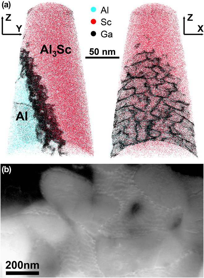
A sample was produced using laser metal deposition (LMD)Reference Herzog, Seyda, Wycisk and Emmelmann49,Reference DebRoy, Wei, Zuback, Mukherjee, Elmer, Milewski, Beese, Wilson-Heid, De and Zhang50 from an Al1.0Sc0.6Zr (wt%) powder using fiber coupled diode laser system with a wavelength of 976 nm and a beam diameter of 1.8 mm. Ar was used as a carrier and shielding gas. A track offset of 1000 µm, a height offset of 750 µm, a laser power of 1800 W, and a deposition speed of 600 mm/min were used. Since a Sc content of 1 wt% is hypereutectic, upon cooling Al3(Sc,Zr) particles can form as primary precipitates directly from the meltpool during the additive manufacturing process. Due to the low lattice mismatch of the Al3(Sc,Zr) precipitates and the Al matrix of below 1%,Reference Harada and Dunand51 these primary precipitates act as efficient nuclei for the solidifying Al matrix as the temperature drops. The lattice misfit along the arising interface is compensated by misfit dislocations leading to a semicoherent interface of this primary precipitate with the Al matrix.
The APT specimen was prepared by the commonly used lift-out protocol described, e.g., in Ref. Reference Thompson, Lawrence, Larson, Olson, Kelly and Gorman43 using a FEI Helios NanoLab 600i focused ion beam/scanning electron microscope (FIB/SEM) dual beam device. The tip was placed on a silicon microtip coupon and sharpened by means of annular milling patterns at 30 kV acceleration voltage with ion currents ranging from 0.23 nA to 40 pA. A final low kV cleaning mill at 5 kV acceleration voltage and 40 pA was applied. APT experiments were performed in a Cameca LEAP 5000 XS at a base temperature of 60 K, a pressure of less than 10−10 mbar in the laser mode using a pulse energy of 0.1 nJ, a pulse frequency of 833 kHz, and a detection rate of 2%. 3D reconstruction was conducted using commercial software IVAS version 3.6.14. Voxel-based analysis such as isosurfaces was performed with a grid spacing of 1 nm, applying a delocalization of 3 nm.
Figure 1(a) shows the elemental distribution obtained from the APT analysis of a specimen that contains a phase boundary between a primary Al3(Sc,Zr) precipitate and the Al matrix. Figure 1(b) is an electron channeling contrast image collected in the scanning electron microscope that shows strong atomic-number contrast in addition to the channeling contrast. The Ga distribution in the corresponding atom map forms a complex pattern that can likely be attributed to the presence of a high density of interfacial dislocations where Ga can segregate. This network of misfit dislocations is highly decorated by Ga atoms after FIB tip preparation. Additional to the misfit dislocation network, two single dislocations leading into the Al matrix are enriched in Ga as well. The Ga content in the misfit dislocations can reach up to 25 at.%; in the single dislocation, it reaches up to 11 at.%. The effect of decoration of defects with Ga is 2-fold: on the one hand side, it enables observation of dislocations and dislocation-based phenomena such as, e.g., heterogeneous nucleation in APT datasets that might otherwise be overlooked if dislocations are not decorated by any alloying element. On the other hand, enrichment of Ga up to 25 at.% will clearly have an influence on the interface and bias any quantification of elemental segregation on the interface.
(a) An APT measurement of a tip that contains the phase boundary of a primary Al3(Sc,Zr) precipitate and the Al matrix. 0.05% of Al atoms, 2% of Sc atoms, and 100% of Ga atoms are shown. Misfit dislocations along the interface are highly enriched in Ga which stems from FIB sample preparation; (b) an ECCI micrograph of the same type of misfit dislocation network.
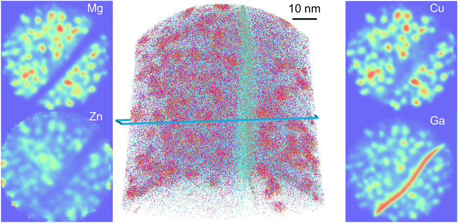
The local composition of these specific features does not otherwise reveal any specific segregation in this Al–Sc–Zr alloy, which makes them extremely difficult or impossible to visualise. The effect of Ga has on the local solute distribution is also unknown and difficult to quantify. This can become problematic for instance in a case where segregation is expected. Figure 2 shows the tomographic reconstruction from an analysis of a specimen containing a high-angle grain boundary in a model Al–Mg–Zn–Cu alloy in the peak aged state, i.e., after 24 h at 120 °C aging following solution heat treatment at 475 °C for an hour and water quenching. The specimen was prepared via site-specific lift-out on a Ga-FIB. In Fig. 2, the Guinier–Preston (GP) zones in the bulk of the grains are clearly visible, as well as the grain boundary itself that shows a slight depletion of all solutes but a very strong segregation of Ga. The main unknown which remains is how the presence of Ga to the defect may have perturbed the segregation behavior of other solutes. The strong attraction of Ga to defects, specifically in Al-alloys, brings into question the validity of quantification of the segregation to crystalline defects in this alloy family, which may explain why the literature on this topic is rather sparse.Reference Moody, Tang, Gault, Ringer and Cairney33,Reference Taheri, Sebastian, Reed, Seidman and Rollett47,Reference Tang, Gianola, Moody, Hemker and Cairney52
APT reconstruction containing a high-angle grain boundary from a specimen prepared in a model Al–Mg–Zn–Cu alloy with a Ga-FIB, showing the 2D compositional maps for the main three solutes and of Ga, highlighting the strong segregation of Ga to the boundary and the precipitate–matrix interfaces.
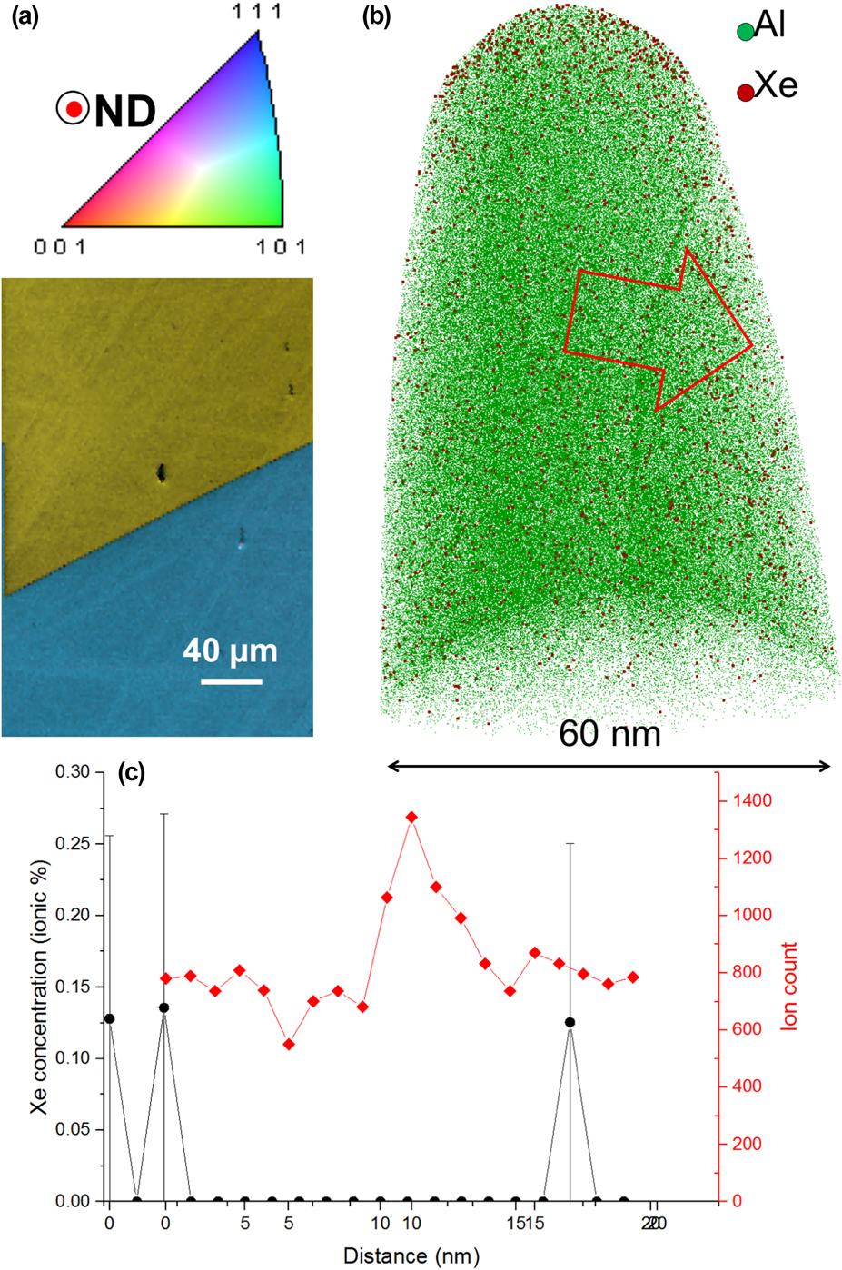
The use of alternative ion milling sources, particularly Xe, has recently been of significant scientific interest. A pure-Al sample for scanning electron microscopy was mechanically polished to a mirror finish, and subsequently a coarse electron-backscattered electron diffraction scan was performed to identify a random high-angle boundary, as shown in Fig. 3(a). The selected grain boundary has a minimum misorientation of approx. 49° about the 〈24 2 15〉 axis. We then used the protocol from Ref. Reference Thompson, Lawrence, Larson, Olson, Kelly and Gorman43 for in situ lift-out but simply used a Xe-plasma in a FEI Helios PFIB to perform target preparation of a random high-angle grain boundary (RHAGB), with the main cuts and sharpening steps performed at 30 kV acceleration voltage, followed by a cleaning step at 5 kV. Figure 3(b) is the tomographic reconstruction resulting from the corresponding analysis. Only a fraction of the Al ions is shown, but all the ions detected in ranges corresponding to the mass-to-charge ratios of Xe are displayed (red dots). The grain boundary is visible as a region of slightly higher point density within the tomogram. A composition profile calculated in a 10 nm-diameter cylinder across the boundary and is plotted in Fig. 3(c). The number of ions within each bin of the profile is also plotted, in red, as a function of the distance along the cylinder. The peak in this profile corresponds to the position of the grain boundary. Only a small amount of Xe is detected in the profile, with no noticeable peak at the location of the grain boundary. This opens the opportunity for more accurate analysis of crystalline defects in Al-based alloys.
(a) EBSD coloured orientation and image quality maps combined around the selected grain boundary in pure-Al; (b) tomographic reconstruction from the corresponding analysis; (c) Xe-composition profile calculated along the red arrow in (b) and local point density along the cylinder used to calculate the profile.
B. Line defects near oxidized carbides in Ni-based superalloys
We have also turned our attention to deformed microstructures in Ni-based superalloys exhibiting a γ/γ′ microstructure.Reference Kontis, Li, Collins, Cormier, Raabe and Gault53–Reference Makineni, Lenz, Kontis, Li, Kumar, Felfer, Neumeier, Herbig, Spiecker, Raabe and Gault55 In a recent article, we reported on the strong segregation of γ stabilizing elements, primarily Cr and Co onto a complex network of linear features appearing within γ′ precipitates in various alloys, incl. IN782 and MC2. For those samples, the specimens had been prepared in regions of the deformed microstructure imaged by cECCI that showed a very high dislocation density. The features observed in these tomographic reconstructions were hence assumed to be dislocations that are decorated by solutes, similar to those reported by Kuzmina et al. in their correlative TEM/APT investigation of confined transformations in the Fe–Mn system.Reference Kuzmina, Herbig, Ponge, Sandlobes and Raabe56 Composition profiles though the features revealed either single peaks of segregation corresponding to a dislocation or double peaks that might be the sign of two partial dislocations surrounding an extended defect. Interestingly, the segregation to the front and trailing partials, which are of different kinds, bear different amounts of solutes.
This work shed light on a long-standing question of whether pipe diffusion can take place within superalloys during high temperature deformation, e.g., creep, and, more importantly perhaps, which elements are subject to pipe diffusion. Pipe diffusion relates to an enhanced diffusivity via processes occurring in the core of individual dislocations or arrays of dislocations.Reference Love57,Reference Legros, Dehm, Arzt and Balk58 Pipe diffusion is expected to accelerate the transport of elementsReference Legros, Dehm, Arzt and Balk58,Reference Kolbe, Dlouhy and Eggeler59 and hence play a major role in the high temperature creep that leads to the rafting of the γ′ precipitates and their progressive dissolution.Reference Pollock and Argon60,Reference Reed61 Here we provided quantitative evidence that Cr and Co, two γ stabilizers exhibited a strong tendency to be attracted, and to segregate to dislocations. A likely possibility is that these solutes are carried along as the dislocations move through the γ/γ′ interface. Indeed, no radial gradient of solutes was observed near the dislocations, which would result from the diffusion of solutes toward the dislocations during cooling for instance.
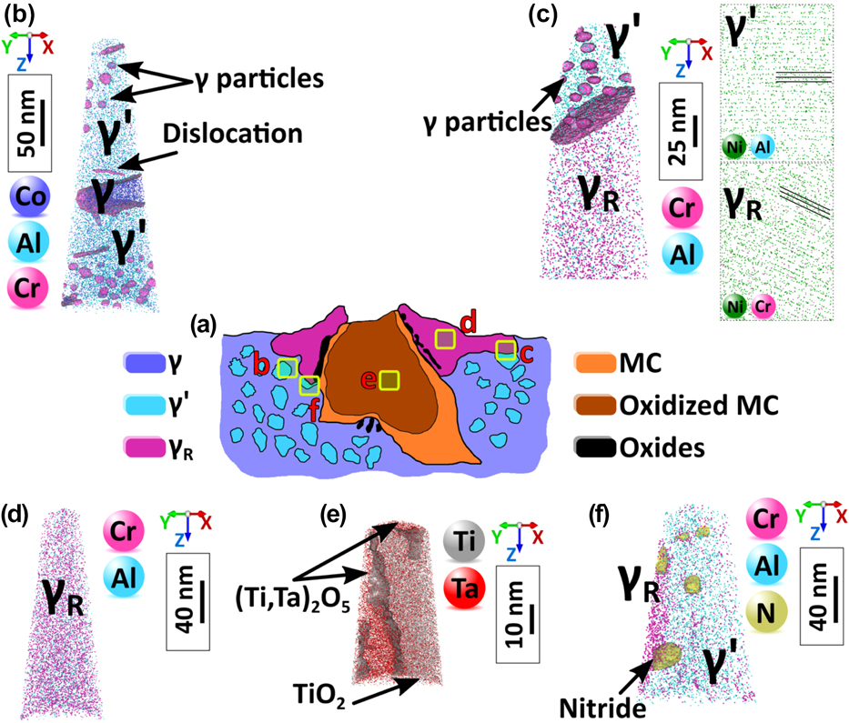
In addition, the high concentration of defects in some regions of the microstructure likely assists mass transport significantly. Figure 4 summarizes the structural changes revealed by APT in the surroundings of a carbide that was oxidized during static exposure to air at 750 °C for 50 h of a fully heat-treated polycrystalline superalloy IN792. The carbide has turned into a complex oxide, dislocations carrying Cr and Co are observed in the original grains, a number of small recrystallized grains are observed in the vicinity of the oxidized carbide, and these grains are a single phase with a composition that shows a severe depletion of Cr and, to a lesser extent Co, leading to a solid solution γR with a previously unreported composition. We proposed a mechanism to rationalize these observations. The oxidation of the Ta-rich carbide leads to a strong volume expansion, expected to be approximately a factor of 2,Reference Connolley, Reed and Starink62 which causes plastic deformation of the surrounding microstructure. By carrying solutes, potentially over large distances, this deformation can explain the local destabilization of the equilibrium and the subsequent dissolution of the main strengthening phase present in the original γ/γ′ microstructure. We observed this process in a range of different alloys and for multiple sources of deformation and hence believe this process to be of general nature. The weakening of the structure close to the oxidized carbide can therefore be directly attributed to the local deformation combined with the mass transport assisted by the high density of dislocations that carry their own solute atmospheres and facilitate pipe diffusion. This weakening of the structure will impact the crack initiation and lifetime of engineering parts in service.
(a) Schematic illustration of the oxidized carbide. (b) APT analysis in the γ/γ′ region showing dislocations and γ precipitates within the γ′ precipitate. (c) APT reconstruction showing γ′/γR interface, γ precipitates within γ′, and two sets of crystallographic planes from the same crystallographic direction from each side of the interphase interface. (d) APT reconstruction within the γR solid solution in the recrystallized grain. (e) APT reconstruction from the oxidized MC carbide showing two different oxide compositions TiO2/(Ti,Ta)2O5. (f) APT reconstruction showing a γR/γ′ interface and small nitrides at the γR/γ′ interface and within the γ′ precipitate, indicative of the penetration of N within the structure, also likely assisted by the deformation process (Reprinted with permission from Ref. Reference Kontis, Collins, Wilkinson, Reed, Raabe and Gault54.).
C. Segregation to stacking faults
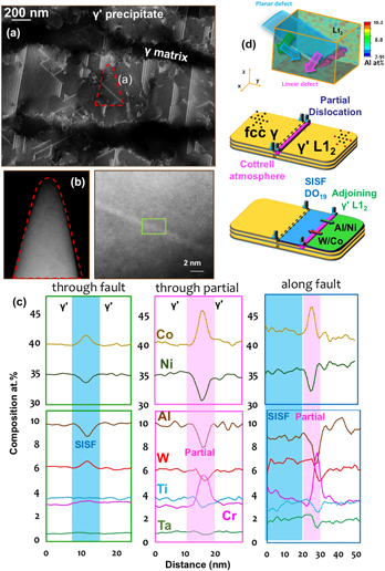
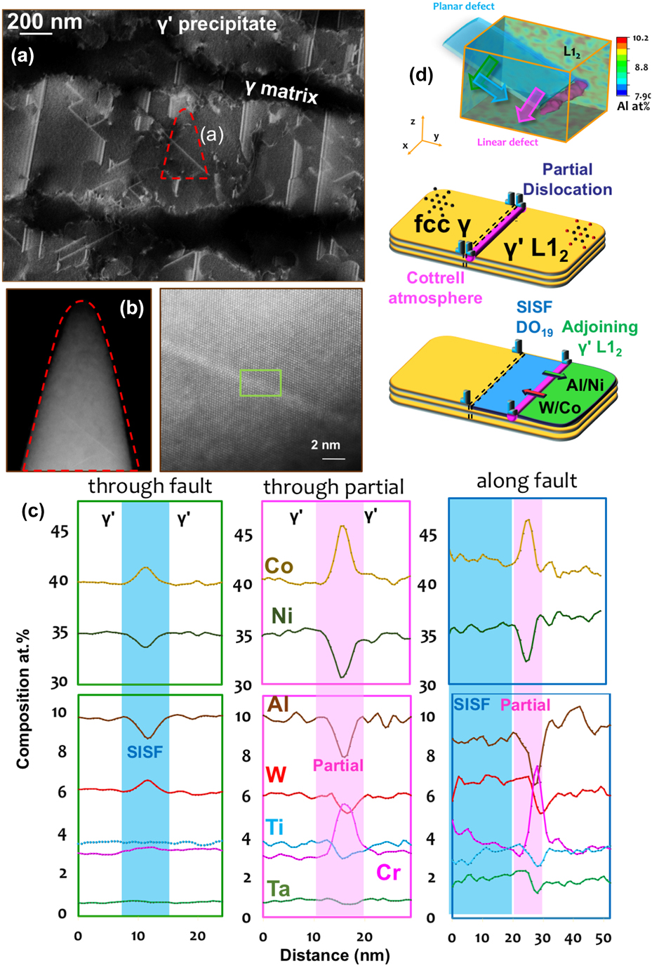
We recently devoted significant effort to reveal and quantify segregation to stacking faults formed during creep deformation of γ–γ′ Co-based superalloys. These alloys show very high creep resistance and are being developed for application as the blade material in high-temperature gas turbine. These alloys are made of a disordered solid solution matrix with face-centered cubic (fcc) crystal structure (γ phase) and ordered precipitates with a L12 crystal structure (γ′ phase). Depending on the temperature and the external stress, the deformation mechanism in the microstructure results in the shearing of γ′ either by the creation of antiphase boundaries, stacking faults, and/or micro-twinning. In the past decade, numerous articles reported solute segregations to these defects, in particular to stacking faults.Reference Titus, Mottura, Babu Viswanathan, Suzuki, Mills and Pollock63,Reference Eggeler, Müller, Titus, Suzuki, Pollock and Spiecker64 It was then proposed that the rate limiting steps for creep deformation are related to local solute diffusivity in the vicinity of these defects. Here, as detailed in Fig. 5(a), we used electron-channeling contrast imaging in the scanning electron microscopeReference Zaefferer and Elhami65 to guide the selection of a region-of-interest in the microstructure to analyze a single stacking-fault by APT. In a second step, high-resolution scanning-transmission electron microscopy was used to confirm the presence and characterize the nature of the fault, as shown in Fig. 5(b). APT provides the full compositional field, and, in Fig. 5(c) are plotted the composition profiles through the stacking fault, the leading partial dislocation and along the stacking fault. These profiles reveal significant variations across the fault, with a clear segregation of Co and W and a depletion of Al. This can be explained by the local change from a face-centered cubic L12 ordered structure to hexagonal-close packed DO19 ordered structure, which is the structure of the stable Co3W phase. The leading partial dislocation that creates the fault in the ordered precipitate sees segregation of Cr and Co, which are both partitioned to the γ matrix, similarly what was observed in the Ni-based systems, as well as a depletion of Al. Finally, we could show evidence of a pile-up of Al ahead of the fault that had previously not been reported.Reference Makineni, Kumar, Lenz, Kontis, Meiners, Zaefferer, Zenk, Eggeler, Neumeier, Spiecker, Raabe and Gault66,Reference Makineni, Lenz, Neumeier, Spiecker, Raabe and Gault67 The gradients observed along the fault suggests the integration of W and Ta and subsequent diffusion along the fault, through the partial dislocation, as schematically depicted in Fig. 5(d). This change of composition ahead of the partial is expected to affect the pace at which the partial can move through the ordered precipitate and hence the overall mechanical behavior of the material under load.
(a) ECCI of a crept CoNi-based superalloy taken near the [110] direction showing the rafted γ′ parallel to the tensile loading direction. (b) Low- and high-magnification scanning transmission electron micrographs (high-angle annular dark field) of the APT specimen along the [110] zone direction showing planar stacking fault in bright contrast. (c) Composition profiles across stacking fault, leading partial dislocation, and along the stacking fault plane. (d) Full three-dimensional compositional field of Al and schematic illustration of the diffusional processes taking place (Reprinted with permission from Ref. Reference Makineni, Kumar, Lenz, Kontis, Meiners, Zaefferer, Zenk, Eggeler, Neumeier, Spiecker, Raabe and Gault66.).
D. Segregation in CIGS
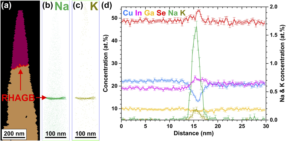
Solar cells based on polycrystalline CuInGaSe2 thin films have attracted considerable attention in the past few years for their high conversion efficiency. Cu(In,Ga)(S,Se)2-based thin-film solar cells achieve power conversion efficiencies of up to 22.9%Reference Kato68 despite the polycrystalline nature of the absorber material. Hence, it is essential to link the structural and chemical properties with the optoelectronic properties of defects such as grain boundaries.Reference Cojocaru-Mirédin, Schwarz and Abou-Ras41 Figures 6(a)–6(c) show a correlative transmission Kikuchi diffraction (TKD)—APT study of a RHAGB from a Cu(In,Ga)Se2-based absorber.Reference Schwarz, Stechmann, Gault, Cojocaru-Mirédin, Wuerz and Raabe69 Beside the chemical fluctuations of the matrix elements, we detect co-segregation of the Na and K at the grain boundary, as shown in Figs. 6(b) and 6(c), where the Gibbs excess values are 3.2 at/nm2 and 0.4 at/nm2 for Na and K, respectively. This is reflected in the concentration profile across the RHAGB in Fig. 6(d) that exhibits a clear In and Se enrichment as well as Cu depletion. In some cases, we also observe slight Ga depletion. Here, the alkali metals are out-diffusing from the soda-lime glass substrate, which contains Na2O and K2O. At twin boundaries, we do not detect variations of the matrix elements and segregation phenomena. The atomic redistribution, more precisely the Cu depletion, at the RHAGB indicates a downward band bending at the GB, which acts as a neutral hole barrier.Reference Abou-Ras, Schmidt, Schäfer, Kavalakkatt, Rissom, Unold, Mainz, Weber, Kirchartz, Simsek Sanli, van Aken, Ramasse, Kleebe, Azulay, Balberg, Millo, Cojocaru-Mirédin, Barragan-Yani, Albe, Haarstrich and Ronning70 Furthermore, the formation of compensating InCu2+ donors might be reduced by the segregation of Na and K, which can form charge neutral NaCu0 and KCu0 point defects. Latter ones do not create any defect level within the band gap according to DFT calculations.Reference Wei, Zhang and Zunger71 Indeed, RHAGBs exhibit enhanced nonradiative recombination compared to twin boundaries, but which are still <1 × 104 cm/s.Reference Abou-Ras, Schmidt, Schäfer, Kavalakkatt, Rissom, Unold, Mainz, Weber, Kirchartz, Simsek Sanli, van Aken, Ramasse, Kleebe, Azulay, Balberg, Millo, Cojocaru-Mirédin, Barragan-Yani, Albe, Haarstrich and Ronning70 The reason for this electrical passivation might be the abovementioned atomic redistribution and segregation of alkali metals.
(a) TKD measurement of an APT specimen from a Cu(In,Ga)Se2 thin-film. The red line marks a RHAGB. (b) and (c) Reconstructed APT dataset showing co-segregation of Na and K atoms at the RHAGB. (d) 1D concentration profile across the RHAGB showing an atomic redistribution (Reprinted with permission from Ref. Reference Schwarz, Stechmann, Gault, Cojocaru-Mirédin, Wuerz and Raabe69.).
E. Phase nucleation at crystalline defects
A detailed study of the segregation of Mn to linear defects in a model Fe-9Mn binary alloy by a combination of APT and transmission electron microscopy led to the possible detection of confined phases, nucleated at dislocations that are not isostructural with the host matrix.Reference Kuzmina, Herbig, Ponge, Sandlobes and Raabe56,Reference Kwiatkowski da Silva, Leyson, Kuzmina, Ponge, Herbig, Sandlöbes, Gault, Neugebauer and Raabe73 These are akin to the concept of complexions, a term that describes the interfacial state in local equilibrium with its abutting phase(s)Reference Cantwell, Tang, Dillon, Luo, Rohrer and Harmer74,Reference Rupert75 One of the most interesting aspects of this study is the reasoning that there is a strong interplay between the local structure and the local composition of a specific microstructural feature. Further analyses of crystalline defects in this same system led us to further highlight the specific behavior of these confined regions, providing evidence of confined spinodal decomposition of the solutes that are adsorbed to the grain boundary.
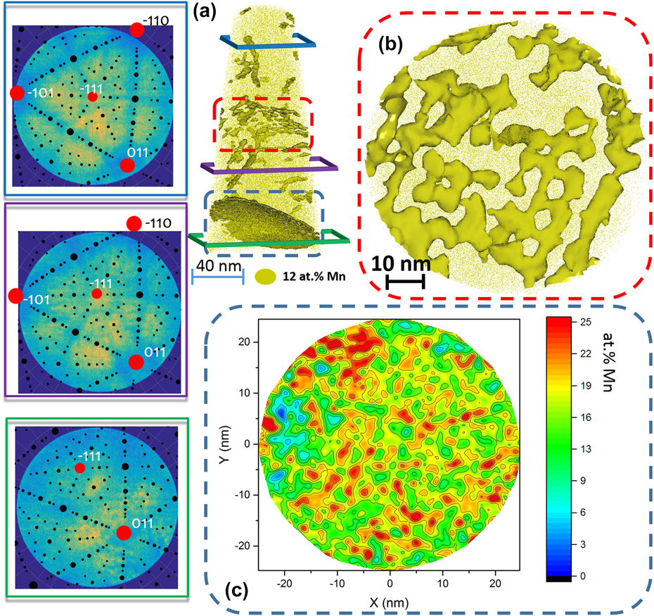
This is highlighted in Fig. 7 that details the information obtained from a single dataset. In Fig. 7(a), the structural information extracted from the partial crystallographic information available within the detector hit maps shown in Fig. 7(a) allow for full misorientation determination.Reference Gault, Moody, Cairney and Ringer27,Reference Breen, Babinsky, Day, Eder, Oakman, Trimby, Primig, Cairney and Ringer29,Reference Moody, Tang, Gault, Ringer and Cairney33 Figure 7(b) is a close-up on the low-angle grain boundary located in the central part of the dataset, which shows a clear pattern of decorated line defects along which composition fluctuates. Figure 7(c) is a two-dimensional composition map of the high-angle grain boundary, located toward the bottom of the dataset, and it shows clear compositional fluctuations.
APT analysis of a grain boundary decorated with Mn after 6 h at 450 °C. (a) The 12.5 at.% Mn iso-concentration surfaces (12.5 at.% Mn was chosen as a threshold value to highlight Mn-enriched regions). The detector map of the regions marked by the blue, purple, and green frames, respectively. The corresponding stereographic projections (black dots) after the identification of the main poles in the map (red dots) were superimposed. (b) Detail of the twisted low-angle grain boundary marked by the red dashed box in (a) as revealed by the iso-concentration surfaces. The grain boundary highlighted by the blue dashed box in (a) was exported and displayed in (c) using an in-plane concentration analysis inside the grain boundary plane (caption adapted and figure reproduced with authorization from Ref. Reference Kwiatkowski da Silva, Ponge, Peng, Inden, Lu, Breen, Gault and Raabe72, for which the content is covered by a CC-Attribution 4.0 licence authorizing reuse of content with modification).
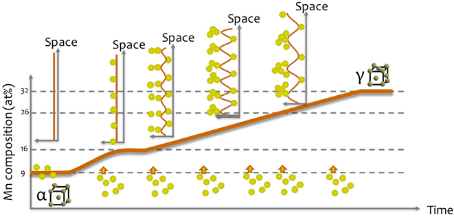
At 450 °C, a miscibility gap appears in the Fe-Mn phase diagram that can lead to a spinodal decomposition.Reference Kwiatkowski da Silva, Ponge, Peng, Inden, Lu, Breen, Gault and Raabe72 As the local composition of a microstructural feature reaches a certain threshold composition, compositional fluctuations along the linear defects and planar defects can be interpreted as a confined spinodal fluctuations. Indeed, during aging at high temperature, solutes will tend to segregate to the defects to help lower the system’s free energy, as the segregation keeps proceeding, the confined system at the defect will progressively reach the composition at which the miscibility gap appears in the Fe–Mn system at the grain boundary. This triggers phase separation and compositional fluctuations appear. This is summarized schematically in Fig. 8. Such strong compositional variations within the grain boundary will greatly influence the succession of phase formations and hence development of the microstructure and we showed that these likely influence the nucleation of austenite in this specific alloy and that they could explain the mechanical properties of the alloy in the early stage of aging.Reference Kuzmina, Ponge and Raabe76
Schematic view of the progressive evolution of the Mn segregation over time: as Mn segregates to the boundary, the composition reaches point at which spinodal fluctuations appear in space, as the maximum amplitude of the spinodal waves is reached, the wavelength of the fluctuations increases.
F. Heterogeneous nucleation of hydrides in titanium
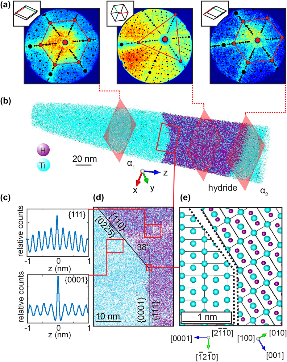
Titanium and its alloys are known for their high affinity for hydrogen and their tendency to form thermodynamically stable hydrides.Reference Numakura and Koiwa77 Ti-hydrides are known to influence the brittle fracture of Ti-alloys during service.Reference Briant, Wang and Chollocoop78,Reference Nelson79 It was reported that the high susceptibility for hydride formation of Ti can lead to the formation of spurious hydrides during specimen preparation that affect the local microstructure before precise characterization is possible.Reference Gammon, Briggs, Packard, Batson, Boyer and Domby80,Reference Ding and Jones81 We exploited the formation of hydrides, subsequent to focused-ion beam irradiation during specimen preparation, to investigate stable hydrides by APT.Reference Chang, Breen, Tarzimoghadam, Kürnsteiner, Gardner, Ackerman, Radecka, Bagot, Lu, Li, Jägle, Herbig, Stephenson, Moody, Rugg, Dye, Ponge, Raabe and Gault82 Commercially pure Ti and multiple alloy systems were investigated. Figure 9 shows a hydride that has nucleated in a binary Ti–2Fe alloy. Here again, atom probe crystallography analysis of the detector hit maps reveals key features. First, the hydride has formed at a grain boundary, as assessed by the shift in the position of the pole that exhibits a 6-fold symmetry corresponding to the {0002} set of planes of the hexagonal-close-packed α-Ti in Fig. 9(a). The orientation between the two grains changed by approximately 5.4°. Second, the region with high hydrogen composition, visible in Fig. 9(b), has transformed into a hydride, which is revealed by the change in the pole pattern in the detector hit map. A clear {111} pole aligns with the {0002} pole of the bottom grain. This observation is indicative of an orientation relationship that agrees with previous reports from transmission electron microscopy.Reference Numakura and Koiwa77 The plane spacing was assessed by spatial distribution maps,Reference Moody, Gault, Stephenson, Haley and Ringer32 displayed in Fig. 9(c), and the planes themselves are visualized in Fig. 9(d). A model of the interface is proposed in Fig. 9(e). This study allowed for quantification of the composition and interfacial segregation behavior of hydrides that have grown subsequently FIB-based sample preparation most likely via a heterogeneous nucleation process.
Atom probe crystallography analysis of a hydride precipitated at a α low-angle grain boundary in Ti–2Fe: (a) patterns formed on the detector during the analysis exhibiting the typical symmetries from the local crystalline phase highlighted by the superimposed stereograms; (b) APT reconstruction and (c) spatial distribution maps revealing the presence of atomic planes in the tomographic reconstruction near the α-Ti/hydride interface shown in (d); (e) model of the faceted α/hydride (Reprinted with permission from Ref. Reference Chang, Breen, Tarzimoghadam, Kürnsteiner, Gardner, Ackerman, Radecka, Bagot, Lu, Li, Jägle, Herbig, Stephenson, Moody, Rugg, Dye, Ponge, Raabe and Gault82.).
IV. SUMMARY
Herein, we have reviewed the application of APT, in conjunction with electron microscopy-based techniques, to study the local composition of individual structural defects that differ from their surrounding due to segregation. These confined regions near or at defects exhibit their own partitioning behaviour and can be considered as separate confined phases or complexions (this is a terminology debate that falls outside the scope of the current article). APT is ideally suited to study segregation to crystalline defects and the unique insights brought by the application of the technique are critical to understand phenomena and processes at the nanoscale and hence predict the microstructural evolution during the lifetime of parts made from these typical engineering alloys.
ACKNOWLEDGMENTS
Uwe Tezins and Andreas Sturm are acknowledged for their constant support in running the atom probe facilities at MPIE. The BMBF is acknowledged for financial support to the UGSLIT project, which enabled the purchase of the PFIB and the funding of AS to develop the applications of this instrument. BG is deeply indebted to The Max-Planck Gesellschaft for the funding of the Laplace Project, which funded an instrument as well as LTS, IM, and PKo who are pushing the boundaries of what APT can do. HZ and YC acknowledge support from the Chinese Scholarship Council. SKM and JH acknowledge support from the DFG/SFB TR 103 project A4. BG & SKM are grateful to Steffen Neumeier, Malte Lenz, and Erdmann Spiecker for from FAU for the collaboration on the stacking faults in Co-based alloys. BG and TS acknowledge financial support from the DFG through the CorrKest project in collaboration with S. Siebentritt from U Luxembourg. SKM and AB are grateful for funding from the AvH Stifftung. PKü and EAJ acknowledge funding for the AProLAM project, funded jointly by the Fraunhofer Society and the Max Planck Society in their strategic cooperation framework. ZP is grateful for funding of the InitialWear project, funded by the Max-Planck-Gesellschaft (MPG) and the Fraunhofer-Gesellschaft. A.K.S. is grateful to the Brazilian National Research Council (Conselho Nacional de Pesquisas, CNPQ) for the Ph.D. scholarship through the “Science without Borders” Project (203077/2014-8).
In terms of contributions to the writing of this article, BG wrote most of it, with direct input from some of the authors. DR is placed as last author because he is the Chef. Others helped prepare the figures. All the authors were given a chance to comment on the manuscript, comments that were mostly blended into the article or completely ignored by the first author. The rest of the authors are listed alphabetically to avoid any possible conflicts.


 Open access