


Introduction
An earlier version of this paper was presented at the 18th European Radar Conference (EuRAD 2021) and was published in its proceedings [Reference Quint, Nuss, Diewald and Zwick1].
Among digital radar systems, orthogonal frequency-division multiplexing (OFDM) radar systems have been of interest for many years [Reference Levanon2–Reference Hakobyan and Yang4]. One big advantage is that the OFDM radar scheme can be combined with multiple-input multiple-output (MIMO). Also, by choosing system parameters depending on the users need, the OFDM radar system can be adapted to different requirements [Reference Hwang, Yang, Wu, Li and Li5, Reference Nuss, Mayer and Zwick6].
The achievable range resolution of a radar system is limited by the transmit signal bandwidth. To achieve a high range resolution, a high radar bandwidth is needed. In OFDM radar, as in all digital radar schemes, this goes hand-in-hand with the need for a high sampling rate, requiring faster analog-to-digital (ADC) and digital-to-analog converters (DAC) which make the radar system more expensive and increase the computational effort as they produce a lot of data.
In order to get a high bandwidth and thus good range resolution while keeping the sampling rate low at the same time, multiple techniques have been investigated. In [Reference Pfeffer, Feger and Stelzer7], the carrier frequency of the OFDM signals are increased after one OFDM symbol block by the bandwidth of the OFDM symbol block itself. The concept is also shown in [Reference Schweizer, Knill, Schindler and Waldschmidt8, Reference Lellouch, Pribic and van Genderen9]. In [Reference Lellouch, Pribic and van Genderen9], the carrier frequency is not increased after every OFDM symbol block but chosen in a pseudo-random frequency hopping pattern. For the mentioned approaches, the duration of the OFDM signal, which is used for range and velocity estimation, is increased by the same factor as the bandwidth. Therefore, the maximum unambiguous velocity is reduced by this factor. A frequency hopping approach is presented in [Reference Knill, Schweizer, Sparrer, Roos, Fischer and Waldschmidt10]. Not only the carrier frequency is chosen in a pseudo-random pattern, but also the OFDM bandwidth and the signal duration. This doesn't reduce the maximum unambiguous velocity but a compressed sensing algorithm is needed for range and velocity estimation which significantly increases the computational effort.
The OFDM signal bandwidth can also be increased without increasing the sampling rate by multiplying the OFDM signal with a frequency comb after the digital-to-analog conversion in the transmitter [Reference Nuss, Mayer, Marahrens and Zwick11]. This technique is further called frequency comb OFDM radar. The comb frequencies are allocated in a way, that their spacing is equivalent to the OFDM bandwidth.
As the OFDM signal duration is not increased, the maximum unambiguous velocity is not reduced. Also, the processing effort is not significantly higher than for standard OFDM radar. The drawback of this approach is a decreased maximum unambiguous range.
For this technique, a test setup was implemented to show the functionality. This test setup consisted of software defined radios (SDRs) for the OFDM signal and frequency comb generation and data storage and multiple connectorized IQ mixers for the multiplication of the OFDM signal with the frequency comb [Reference Nuss, Mayer, Marahrens and Zwick11]. To integrate this frequency comb OFDM radar technique in industrial or automotive radar systems, a compact realization must be thought of.
Frequency comb based OFDM radar
The range resolution Δr of any radar system is described by

where c 0 is the speed of light in vacuum and B is the transmit signal bandwidth [Reference Levanon and Mozeson12]. To obtain a good range resolution, a high bandwidth is necessary. As explained in [Reference Nuss, Mayer, Marahrens and Zwick11], this can be performed by multiplying a narrowband OFDM signal with a frequency comb consisting of L frequencies in the transmitter as shown in Fig. 1.
Multiplication of the OFDM signal with the frequency comb (based on [Reference Quint, Nuss, Diewald and Zwick1]).

The result of this multiplication are L adjacent OFDM spectra consisting of the same information symbols. Those spectra will be further called subbands. In order to obtain one single broadband spectrum, the subbands are not allowed to have a spectral separation. This leads to the fact that the spacing of the comb frequencies needs to be equal to B. The multiplication product of an OFDM signal with the bandwidth B and a frequency comb consisting of L frequencies is a OFDM signal with the increased bandwidth L ⋅ B. As explained in [Reference Nuss, Mayer, Marahrens and Zwick11], the bandwidth enhancement results in a new range resolution of

In the receiver, the enhanced bandwidth L ⋅ B should be reduced to the original bandwidth B, as the aim of this scheme is to reduce costs by keeping the sampling rate low. This is again performed by a multiplication of the broadband transmit signal with a frequency comb, further increasing the bandwidth. As the goal of the frequency comb OFDM radar scheme is to keep the sampling rate low, the bandwidth of this broadband spectrum must be reduced again. This is done by filtering the middle subband of the bandwidth B. Details on this technique are presented in [Reference Nuss, Mayer, Marahrens and Zwick11].
System considerations
Multiplication architecture
In the frequency comb radar system presented in [Reference Nuss, Mayer, Marahrens and Zwick11], the multiplication of the OFDM signal with the frequency comb is carried out using multiple mixers and multiple single frequencies as shown in Fig. 2(a).
Methods to multiply with a frequency comb. (a) Multiplication using multiple mixers and multiple single frequency sources. (b) Direct multiplication with the frequency comb in a single multiplier.

Those single frequencies are not necessarily phase coherent. Therefore, a calibration must be performed before every operation of the radar. To produce a frequency comb where the comb frequencies are phase coherent, the comb frequencies must be derived from the same source. As the comb frequencies are generated in one source, they are multiplied with the OFDM signal in a single multiplier which heavily reduces the space and cost. This can be seen in Fig. 2(b). Many mixer architectures require a strong local oscillator (LO) signal to drive the mixer. This results in strong intermodulation products. In this radar system, intermodulation can be very disruptive as the OFDM signal and the frequency comb consist of many discrete single frequencies. Therefore, instead of a conventional mixer, the analog multiplier ADL5391 from Analog Devices [13] is used for the multiplication of the OFDM signal with the frequency comb.
To conclude the system considerations regarding the multiplication architecture, there are two main objectives in the design of the radar system:
(i) Generate the frequency comb in a single source to avoid a calibration before every measurement and reduce space and cost.
(ii) Find a system architecture and frequency plan, starting from the used analog multiplier, which minimizes the negative effects of intermodulation products.
Frequency plan
The aimed expanded bandwidth in this proof-of-concept radar system is L ⋅ B = 1 GHz. In order to have a small sampling rate in the ADC and DAC, the OFDM bandwidth shall be as low as possible. A low OFDM bandwidth results in a high number of frequency combs and further in an increased hardware effort. Therefore, a compromise has to be made. For this radar system the OFDM bandwidth is chosen to B = 200 MHz and consequently, the number of comb frequencies to L = 5.
In the following, the frequency plan for the multiplication of the OFDM signal with the frequency comb is explained. This includes the selection of the comb frequencies as well as the baseband OFDM signal. By this selection, the frequency range of the broadband OFDM signal determined. For the frequency plan, there are multiple limitations and considerations:
(i) Building an IQ mixer with the used analog multiplier is rather expensive and complex. Therefore, a heterodyne system setup is chosen, in which both the OFDM signal and the frequency comb are located at a center frequency f c ≠ 0 Hz.
(ii) This heterodyne system concept results in the formation of image spectra in the multiplication of the OFDM signal with the frequency comb. The center frequencies for the OFDM signal and the frequency comb shall be chosen in a way that the spectral separation of the wanted multiplication product and its image spectrum is maximum in order to be able to suppress the image spectrum as good as possible. This is achieved when the image spectrum is centered around 0 Hz, which is obtained when the center frequencies of the OFDM signal and the frequency comb are equal.
(iii) The wanted multiplication product should be in the frequency range of 0 Hz to 2 GHz, which is the specified frequency range of the analog multiplier used [13].
(iv) The feedthrough of the input signal shouldn't disturb the output signal of the multiplication too much. To reduce the power of the intermodulation products, the input power levels are kept low. As the output voltage level of the analog multiplier is the multiplication of the input voltage levels, the output power is even lower than the input power levels. Therefore the feedthrough of the input signal can disturb the output signal if the frequency plan is chosen in an unhandy way.
Those constraints lead to the frequency plan shown in Fig. 3, which is applied in the radar transmitter. In the receiver, the comb frequencies have a small offset [Reference Nuss, Mayer, Marahrens and Zwick11]. The center frequencies of the OFDM signal and the frequency comb are f c, OFDM = f c, Comb = 800 MHz. Among the tested frequency plans, this is the configuration for which the feedthrough of the input signals is the least disturbing. The frequency range of the broadband OFDM signal spans from 1.1 GHz to 2.1 GHz, exceeding the specified range of the analog multiplier by 100 MHz. Test measurements have proven that except from a slightly higher loss, there are no drawbacks.
Frequency plan for the multiplication of the OFDM signal with the frequency comb.

Considerations regarding the frequency comb
The L = 5 comb frequencies forming the frequency comb, are located from 400 MHz to 1.2 GHz with a spacing of B = 200 MHz. The frequency comb is generated in the baseband and consists of a DC voltage and frequency components at 200 MHz and 400 MHz. The mathematical description of the baseband frequency comb in the transmitter is [Reference Quint, Nuss, Diewald and Zwick1]

In the receiver, the comb frequencies have a spacing of B − Δf instead of B, with Δf being the subcarrier distance of the OFDM signal. The frequency comb is then upconverted to its center frequency of f c, Comb = 800 MHz as shown in Fig. 3. This upconversion is also performed in the analog multiplier ADL5391.
Especially in this multiplication, the feedthrough of the input signals in the output spectrum is very critical, as those leaked input frequencies from the baseband comb and the local oscillator (LO) later also multiply with the OFDM signal. In the chosen configuration the input frequencies of the frequency comb are 0 Hz, 200 MHz and 400 MHz for the baseband frequency comb and f c, Comb = 800 MHz for the LO. The signals at 400 MHz and 800 MHz are also present in the upconverted frequency comb and therefore are not critical as the power of the feedthrough is significantly lower than the power of the wanted multiplication products. The feedthrough of the input frequencies 0 Hz and 200 MHz has to be filtered out. Most importantly, a feedthrough of input frequencies between two comb frequencies of the upconverted frequency comb should be avoided as those frequencies can't be suppressed and are also multiplied with the OFDM signal and consequently produce unwanted subbands which overlap with the actually wanted broadband OFDM signal. These undesired subbands have a lower power compared to the wanted broadband OFDM signal. Still, they would reduce the dynamic range of the radar. With the frequency plans in Figs. 3 and 4, this is prevented and therefore, the presented frequency plan is the most suitable one.
Frequency plan for the upconversion of the frequency comb.

Frequency comb generation in the baseband
The frequency comb generation in the baseband is performed by approximating the frequency comb in the time domain with a rectangular-shaped function [Reference Quint, Nuss, Diewald and Zwick1]. Every time period of the ideal frequency comb is divided into n = 4 sections with a constant voltage level as shown in Fig. 5(a).
Approximation of a frequency comb using a rectangular function [Reference Quint, Nuss, Diewald and Zwick1]. (a) Time domain. (b) Spectrum of the approximation function.

The mathematical description of the approximation function is

where T is the duration of one time period of the frequency comb signal. The two middle sections of one period have the same voltage level of 1 V. Therefore, they are combined to one section of longer duration in (4).
The theoretical spectrum of the approximation function is shown in Fig. 5(b). It consists of the five wanted frequency components from −400 MHz to 400 MHz with nearly the same magnitude plus unwanted frequency components at higher frequencies which are damped by at least 9 dB. This relaxes the demand on the further filtering of unwanted frequency components which is an advantage over more widely used frequency comb generation schemes such as those using step recovery diodes [Reference Chia and Sudrajat14]. A drawback though, is the higher hardware effort.
The approximation function from (4) can be generated using a linear feedback shift register circuit, where each output is assigned a voltage level from (4). The circuit to generate the frequency comb and measurement results can be found in [Reference Quint, Nuss, Diewald and Zwick1].
Radar architecture
The block diagram of the heterodyne radar transmitter and receiver are shown in Fig. 6.
Radar architecture (based on [Reference Quint, Nuss, Diewald and Zwick1]): (a) transmitter, (b) receiver.

The OFDM signal is generated digitally with a field programmable gate array (FPGA) in the transmitter and then multiplied with the frequency comb according to Fig. 3. Afterwards the signal is filtered and amplified. All these steps are performed on a compact printed circuit board (PCB), the so called intermediate frequency (IF) board. The broadband OFDM signal is upconverted to the transmit frequency range from 5.1 GHz to 6.1 GHz, which has been chosen in the vicinity of the ISM band from 5.725 GHz to 5.875 GHz, further amplified and filtered in the radio frequency (RF) chain. The used antennas are broadband Vivaldi antennas.
The receiver is built in a similar way, but in reverse. After filtering and amplification, the input signal is downconverted to the frequency range from 1.1 GHz to 2.1 GHz where it is multiplied with the receive comb. Then the subband around f c, OFDM must be filtered out of the multiplication product to reduce the bandwidth again as stated in Section ‘Frequency comb based OFDM radar’. In this proof-of-concept radar system, this is done in the digital domain. The multiplication product is just filtered with a low pass to prevent aliasing.
The core parts of the radar transmitter and receiver are the IF boards, shown in Fig. 7. The components in the radar, which are located on the IF boards are indicated by dashed lines in Fig. 6.
IF Boards: (a) transmitter, (b) receiver.

On the IF boards, the frequency combs in the baseband are upconverted to their center frequency f c, Comb in the upper analog multiplier in Figs. 7(a) and 7(b) according to Fig. 4. The input signals ‘LO IN’ and ‘Sum IN’ are needed for this operation. Each analog multiplier input or output is preceded respective followed by a balun. The analog multiplier can be operated with single-ended or differential signals. In test measurements it has been found that the feedthrough of input signals is much lower for differential signaling. Due to the baluns, the DC component of the baseband frequency comb can't be fed to the multiplier. Therefore, the middle frequency 800 MHz of the upconverted comb added after the multiplication using the input ‘Sum IN.’ This middle frequency of the upconverted comb belongs to the DC part of the baseband comb. After upconversion, the frequency combs are then filtered and multiplied with the respective OFDM signals for the transmit and receive case in the lower analog multiplier.
Measurements and discussion
To verify the functionality of the presented radar architecture in combination with the frequency comb generation published in [Reference Quint, Nuss, Diewald and Zwick1] and frequency comb OFDM radar signal processing presented in [Reference Nuss, Mayer, Marahrens and Zwick11], the radar was setup and test measurements have been performed in an anechoic chamber as shown in Fig. 8. Corner reflectors with an radar cross section (RCS) of 25 m2 have been used as radar targets.
Measurement setup in an anechoic chamber [Reference Quint, Nuss, Diewald and Zwick1].

Radar signals
Transmitter
The output signal of the transmit (Tx) IF board the broadband OFDM signal. The OFDM symbols are pseudo-random quadrature phase-shift keying (QPSK) symbols. Its power spectral density (PSD) is shown in Fig. 9
Spectrum of the output signal of the Tx IF board at position ① in Fig. 7(a).

The wanted multiplication product, which is the broadband OFDM signal from 1.1 GHz to 2.1 GHz is indicated by dashed lines. The L = 5 subbands can be distinguished as they have a different magnitude each. This has two reasons. The first reason is the transfer function of the analog multiplier [13] and the second reason is the difference in the magnitudes of the frequency comb generated with the circuit presented in [Reference Quint, Nuss, Diewald and Zwick1]. During the digital signal processing, a phase and magnitude calibration of the different subbands is performed and the magnitude differences can be corrected. The drawback of this magnitude correction is noise amplification. Furthermore, five unwanted peaks can be seen in the spectrum, with the strongest having a power of −28 dBm at 1.2 GHz. This is the feedthrough of the comb frequency at 1.2 GHz. The total power of the broadband OFDM signal is −24 dBm. To prevent disturbing effects by these peaks, the respective subcarriers are deleted and interpolated in the receiver. Other unwanted frequency components are further filtered in the RF chain shown in Fig. 7(a).
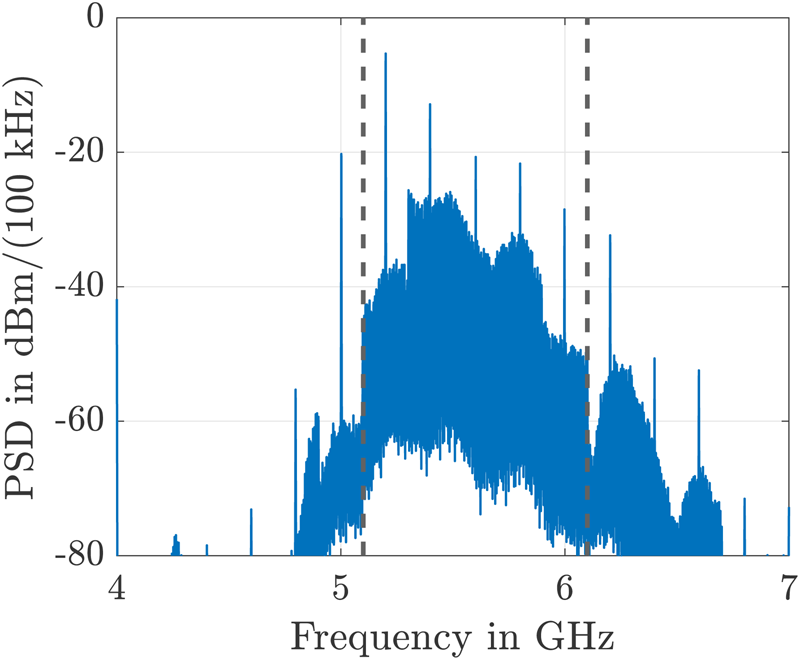
The transmit signal at the antenna input can be seen in Fig. 10. The broadband OFDM signal from 5.1 GHz to 6.1 GHz is indicated by dashed lines. The magnitude difference of the five subbands is 20 dB maximum. This is caused by an insufficient bandwidth of the RF filter which is an in-house designed and fabricated interdigital filter. Again, this magnitude difference can be corrected digitally in the receiver. The drawback of this magnitude correction is noise amplification. The total power of the transmit signal is 0 dBm. As can be seen in Fig. 9, five unwanted frequency peaks occur between 5.1 GHz and 6.1 GHz. The strongest one has a power of −5 dBm. Additionally, a rather strong unwanted subband is present around 6.2 GHz. This is the result of intermodulation in the final amplification stage.
Spectrum of the transmit signal at position ② in Fig. 7(a).
Receiver
In the receiver, the input signal is the attenuated reflection of the broadband OFDM signal sent out by the transmitter. After multiple stages of filtering and amplification and one downcoversion to the frequency range from 1.1 GHz to 2.1 GHz, the broadband OFDM signal is again multiplied with a frequency comb. As explained in Section ‘Frequency comb based OFDM radar’, the frequency comb in the receiver slightly differs from the one in the transmitter to prevent information loss. The output signal of the Rx board, which is the low pass filtered multiplication product of the broadband OFDM signal with the receive frequency comb, is shown in Fig. 11.
Spectrum of the output signal of the Rx IF board at position ③ in Fig. 7(b).

After the multiplication of the broadband OFDM signal with the receive comb, The bandwidth increases. As explained in Section ‘Frequency comb based OFDM radar’, the subband around f c, OFDM has to be filtered in the analog and digital domain, as indicated with dashed lines.
Verification of the frequency comb OFDM radar scheme
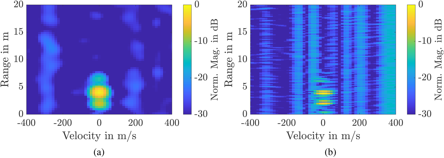
Radar measurements have been recorded with two static corner reflectors at distances of 2 m and 4 m in front of the radar. The range-velocity plots for these measurements are shown in Fig. 12. Here, Fig. 12(a) shows the range-velocity plot for a conventional OFDM radar with a bandwidth of B = 200 MHz. This plot is obtained if only one OFDM subband of the broadband OFDM signal is evaluated. The two targets can hardly be distinguished as they are rather broad in the range direction. When all subbands are used for the radar signal processing, the target peaks become slimmer as shown in Fig. 12(b). Even a gap can be detected between the two targets. As the two targets have a high RCS and the used antenna have a high directivity, the Tx-Rx coupling at r = 0 m is weak compared to the target response and can only hardly be seen in the range-velocity plots in Fig. 12. Vertical lines can be seen in the range-velocity plot in Fig. 12(b). They are induced by non-deterministic run time variations on the FPGA platform, which was used for data generation and signal processing. Although they reduce the dynamic range of the radar, the range resolution of the radar is clearly improved by using the frequency comb bandwidth enhancement.
Measured range-velocity plots for two corner reflector targets. (a) Conventional OFDM radar with a bandwidth of B = 200 MHz [Reference Quint, Nuss, Diewald and Zwick1]. (b) Frequency comb OFDM radar with the bandwidth L ⋅ B = 1 GHz.
Conclusion
The presented radar system shows a compact implementation of a frequency comb OFDM radar. In order to keep the system compact and prevent disturbance by intermodulation products, an analog multiplier is used for the multiplication of the narrowband OFDM signal with the frequency comb. Intermodulation products and feedthrough of the input signals are still present in the transmit signal and in output signal of the IF board in the receiver and need to be taken care of during signal processing. Yet, the presented multiplication architecture and frequency plan minimize the disturbing influences of feedthrough and intermodulation given the presented limitations. The radar functionality was verified by test measurements in an anechoic chamber showing the functionality of the presented radar system in combination with the frequency comb OFDM scheme.
Conflict of interest
The author(s) declare none.
 Alexander Quint obtained the B.Sc. and M.Sc. degrees in electrical engineering and information technology from the Karlsruhe Institute of Technology (KIT), Karlsruhe, Germany, in 2017 and 2020, respectively. Since 2021, he is pursuing a doctorate (Ph.D.E.E.) degree at the Institute of Radio Frequency Engineering and Electronics (IHE) at the KIT. His work mainly focuses on passive components at mmW frequencies and 3D-printed packaging solutions. He also has experience in the design of radar systems and radar hardware.
 Benjamin Nuss obtained the B.Sc. and M.Sc. degrees in electrical engineering and information technology from the Karlsruhe Institute of Technology (KIT), Karlsruhe, Germany, in 2012 and 2015, respectively. In 2021, he received the Dr.-Ing. (Ph.D.E.E) degree from KIT and is currently working as a group leader for radar systems at the Institute of Radio Frequency Engineering and Electronics (IHE). The focus of his work is on the development of efficient future radar waveforms as well as on the design of joint communication and sensing systems. His current research interests include orthogonal frequency-division multiplexing based multiple-input multiple-output radar systems for future automotive and industrial applications.
 Axel Diewald obtained the B.Sc. and M.Sc. degrees in electrical engineering and information technology from Karlsruhe Institute of Technology (KIT) in Karlsruhe, Germany, in 2015 and 2017, respectively. Since 2018, he is pursuing a doctorate (Ph.D.E.E.) degree at the Institute of Radio Frequency Engineering and Electronics (IHE) at the KIT. His main fields of research interest are digital radar target simulation for the purpose of automotive radar sensor validation as well as realistic target modelling.
 Thomas Zwick obtained the Dipl.-Ing. (M.Sc.) and Dr.-Ing. (Ph.D.E.E.) degrees from the Universität Karlsruhe (TH), Germany, in 1994 and 1999, respectively. In October 2007, he became a full professor with the Karlsruhe Institute of Technology (KIT), Germany. He is currently the director of the Institute of Radio Frequency Engineering and Electronics (IHE), KIT. His research topics include wave propagation, stochastic channel modeling, channel measurement techniques, material measurements, microwave techniques, millimeter-wave antenna design, wireless communication, and radar system design.


 Open access