

Introduction
Subsurface exploration of planetary bodies is gaining momentum owing to the recent findings such as the exposed subsurface ice sheets on Martian mid-latitudes (Dundas et al., Reference Dundas, Bramson, Ojha, Wray, Mellon, Byrne, McEwen, Putzig, Viola, Sutton, Clark and Holt2018) and the detection of molecular hydrogen in the plumes of the Saturnian moon Enceladus, showing evidence of hydrothermal activity in the subsurface of the moon (Waite et al., Reference Waite, Glein, Perryman, Teolis, Magee, Miller, Grimes, Perry, Miller, Bouquet, Lunine, Brockwell and Bolton2017). Another recent finding suggests evidence of liquid water trapped below the ice of the South Polar layered deposits in a well-defined, 20-km-wide zone on Mars (Orosei et al., Reference Orosei, Lauro, Pettinelli, Cicchetti, Coradini, Cosciotti, Di Paolo, Flamini, Mattei, Pajola, Soldovieri, Cartacci, Cassenti, Frigeri, Giuppi, Martufi, Masdea, Mitri, Nenna, Noschese, Restano and Seu2018). The subsurface environments of astrobiological and hydrological importance usually include caves, lava tubes, impact or volcanic craters and subglacial conduits. These subsurface targets of interest provide a unique environment for studying geomorphology (e.g. Dundas et al., Reference Dundas, Bramson, Ojha, Wray, Mellon, Byrne, McEwen, Putzig, Viola, Sutton, Clark and Holt2018), geology (e.g. Dartnell et al., Reference Dartnell, Desorgher, Ward and Coates2007), astrobiology (e.g. Cockell et al., Reference Cockell, Bush, Bryce, Direito, Fox-Powell, Harrison, Lammer, Landenmark, Martin-Torres, Nicholson, Noack, O'Malley-James, Payler, Rushby, Samuels, Schwendner, Wadsworth and Zorzano2016; Payler et al., Reference Payler, Biddle, Sherwood Lollar, Fox-Powell, Edwards, Ngwenya, Paling and Cockell2019), geobiology (e.g. Airo et al., Reference Airo, Hauber and van Gasselt2014, Michalski et al., Reference Michalski, Onstott, Mojzsis, Mustard, Chan, Niles and Johnson2017) and mineralogy (e.g. Ehlmann et al., Reference Ehlmann, Mustard, Murchie, Bibring, Meunier, Fraeman and Langevin2011) of an extra-terrestrial body as these environments are pristine and shielded from the often more extreme conditions prevailing on the surface. These subsurface environments hold a diversity of trapped materials and minerals and there can be places to search for habitable environments and test the hypothesis of the presence of microbial life such as extremophiles (Boston et al., Reference Boston, Spilde, Northup, Melim, Soroka, Kleina, Lavoie, Hose, Mallory, Dahm, Crossey and Schelble2001) which might persist in the relatively shielded environment below from energetic particles, ultraviolet (UV) insolation, extreme temperature cycles and the surface oxidizing environment. These subsurface targets can also provide information on the volcanic, tectonic and hydrological history of the extra-terrestrial bodies. Evidence of the effects of climate change on glacial systems have been deciphered from closely monitoring subglacial environments (e.g. de Jacob et al., Reference de Jacob, Bárcena and Finster2011) and in the context of planetary exploration, such findings have implications for understanding climate and landscape evolution. The presence of lava tubes and caves in extra-terrestrial bodies such as Moon and Mars are corroborated with the findings from Mars Onboard Camera aboard the Mars Global Surveyor mission (e.g. Boston, Reference Boston2004), High Resolution Imaging Science Experiment (HiRISE) camera on the Mars Reconnaissance Orbiter (e.g. Cushing et al., Reference Cushing, Titus, Wynne and Christensen2007), Selenological and Engineering Explorer (SELENE) moon mission (e.g. Haruyama et al., Reference Haruyama, Hioki, Shirao, Morota, Hiesinger, van der Bogert, Miyamoto, Iwasaki, Yokota, Ohtake, Matsunaga, Hara, Nakanotani and Pieters2009) and Thermal Infrared Imaging aboard Hayabusa2 to image Asteroid 162173 Ryugu (e.g. Okada et al., Reference Okada, Binzel, Connolly, Yada and Ohtsuki2017). Besides lava tubes, caves formed by other means such as past hydrological activity have also been detected on Mars (e.g. Carr and Wanke, Reference Carr and Wänke1992; McKay et al., Reference McKay, Mancinelli, Stoker, Wharton, Kieffer, Ja-kosky, Snyder and Matthews1992; Malin and Edgett, Reference Malin and Edgett2000). Ashley et al. (Reference Ashley, Robinson, Hawke, van der Bogert, Hiesinger, Sato, Speyerer, Enns, Wagner, Young and Burns2012) have detected lunar caves in Mare Deposits using the Lunar Reconnaissance Orbiter Camera (LROC) Narrow Angle Camera (NAC).
With human exploration of extra-terrestrial gathering pace, the recent trend is to utilize robotic exploration tools for the study of these subsurface targets. Visual analysis is the first step towards exploration and having three-dimensional (3D) information of features rather than just 2D photographic images would provide us detailed knowledge of subsurface features. Real-time mapping in 3D is required for the investigation of planetary geomorphological structures. With the discovery of geological features such as lava tubes and caves on Mars, the curiosity to explore these enclosed geological structures in situ with 3D mapping technologies is overwhelming. Ground-based imagery with rovers provides higher resolution at close range compared with orbiters which have a coarse spatial resolution. i.e. the Mars Exploration Rovers PANcam provided a 0.8 mm pixel−1 Spatial Resolution at 3 m distance (Bell et al., Reference Bell, Squyres, Herkenhoff, Maki, Arneson, Brown, Collins, Dingizian, Elliot, Hagerott, Hayes, Johnson, Johnson, Joseph, Kinch, Lemmon, Morris, Scherr, Schwochert, Shepard, Smith, Sohl-Dickstein, Sullivan, Sullivan and Wadsworth2003) and the ExoMars rover will carry a Panoramic Camera that will provide multi-spectral stereo images with 65° field-of-view (1.1 mrad pixel−1) and high-resolution (85 µrad pixel−1) monoscopic ‘zoom’ images with 5° field-of-view (Griffiths et al., Reference Griffiths, Coates, Jaumann, Michaelis, Paar, Barnes and Josset2006). The panoramic cameras are designed to perform digital terrain mapping and also multi-spectral geological imaging, capturing colour and stereo panoramic images, measuring water vapour abundance and dust. These high-resolution imaging systems can be exploited in future missions for the imaging of inaccessible locations such as crater walls. The limitation of such visible spectrum-based stereoscopic cameras is that they are restricted to imaging only in ambient light conditions. Usage of artificial light sources to illuminate regions of study induce problems such as image saturation of regions close to the light source and shadows created by illumination (Kadambi et al., Reference Kadambi, Bhandari and Raskar2014). Hence, they cannot be used for exploration of subsurface features where there is a complete absence of ambient light conditions. A Red Green Blue-Depth (RGB-D) camera coupled with infrared depth sensor based on the structured light operating principle can address the issue of mapping in 3D in low light to pitch black conditions by combining depth information from the infrared sensor of each pixel with an RGB pixel value. Commercial RGB-D cameras such as the Microsoft Kinect™ first-generation camera operates based on infrared structured light and utilizes a projected intensity pattern to obtain the depth information of each pixel. Artificial lighting may corrupt the pattern and hence these cameras tend to perform well in absence of ambient lighting (Kadambi et al., Reference Kadambi, Bhandari and Raskar2014). The Microsoft Kinect™ camera, primarily used for computer gaming, thus can also prove to be an excellent tool for geomorphological studies by utilizing the infrared depth data to generate short-range 3D maps. Moreno Chávez et al. (Reference Moreno Chávez, Sarocchi, Arce Santana, Borselli and Rodríguez-Sedano2014) have utilized Microsoft Kinect™ as an inexpensive system, with great potential to obtain fast, automatic and accurate grain size distributions of sedimentary deposits. Nakagawa et al. (Reference Nakagawa, Kihara, Tadoh, Serikawa, Lu, Zhang and Li2016) have performed mapping of the underwater terrains using the Microsoft Kinect™. Prante (Reference Prante2013) has utilized Microsoft Kinect™ for characterizing geologic and paleontological features such as the slip-surface roughness in mesoscale.
Subsurface environment's potential for astrobiological study
Subsurface environments also serve as ideal candidates for astrobiological investigation as microbial life can grow in subsurface environments shielded from radiation from by the Solar wind impinging on the surface of the extra-terrestrial body. Subsurface environments can protect biosignatures that can be sought to test the hypothesis of the presence of life. Also, the temperature gradient down these environments tends to be more uniform and can protect rich mineralogy that has not been exposed to the degrading surface conditions. Robotic exploration for astrobiology investigation began in 1976 with the Viking landers on Mars and has grown rapidly and culminated in the recent astrobiology experiment tool on the ExoMars rover – the Pasteur payload (Barnes et al., Reference Barnes, Battistelli, Bertrand, Butera, Chatila, Del Biancio, Draper, Ellery, Gelmi, Ingrand, Koeck, Lacroix, Lamon, Lee, Magnani, Patel, Pompei, Re, Richter, Rowe, Siegwart, Slade, Smith, Terrien, Wall, Ward, Waugh and Woods2006) flag shipped by the Aurora program. The science panoramic camera mounted on the pan/tilt mast, a ground-penetrating radar sounder mounted underneath the rover, a meteorology/environmental sensor package mounted separately on the rover and the Pasteur module-accommodated instruments: an optical colour microscope, a combined Raman spectrometer/laser-induced breakdown spectrometer, a gas chromatograph/mass spectrometer, an oxidant sensor and life marker chip constitute the astrobiological payload. For sample collection, especially from depth of 1.2 to 2 m, the ExoMars carries a drill, which would collect samples from the subsurface which have been isolated from the Martian surface. The need to drill to such depths is because Mars is covered with highly oxidizing material such as hydrogen peroxide that tends to degrade any organic molecule present on the surface. These samples would then be analysed by instruments on the rover which includes a Raman spectrometer, a laser-plasma spectrometer and an infrared spectrometer.
There are many analogues on Earth that provide us a platform for experimental astrobiology. On Earth, Life On ice: Robotic Antarctic eXplorer (LORAX), a robotic mission has been deployed in Antarctica to study the characterization of microbes in the icy sheets of Antarctica as they have the potential to sustain and preserve organic activity (Pedersen et al., Reference Pedersen, Wettergreen, Apostolopoulos, McKay, DiGoia, Jonak, Heys, Teza and Wagner2005). Kapvik, a micro-rover designed by the Canadian Space Agency (CSA) was geared towards identifying and characterizing methane emission on Mars and two analogue missions were carried out in Quebec, Canada on the Jeffrey Mine and in the Norbestos Mine (Qadi et al., Reference Qadi, Cloutis, Samson, Whyte, Ellery, Bell, Berard, Boivin, Haddad, Lavoie, Jamroz, Kruzelecky, Mack, Mann, Olsen, Perrot, Popa, Rhind, Sharma, Stromberg, Strong, Tremblay, Wilhelm, Wing and Wong2015). Methane detection on extra-terrestrial bodies is also a current topic of research. since it is reported in the atmosphere of Mars. Methane on Earth is mainly produced from biological processes and thus its presence on extra-terrestrial bodies like Mars raises curiosity to find its source. Methane could be from potential sources or reservoirs that may be abiotic (e.g. Atreya et al., Reference Atreya, Mahaffy and Wong2007). The abiotic processes include geological production such as serpentinization of olivine (e.g. Oze, Reference Oze2005), UV degradation of meteoritically delivered organics (e.g. Keppler et al., Reference Keppler, Vigano, McLeod, Ott, Früchtl and Röckmann2012, Schuerger et al., Reference Schuerger, Moores, Clausen, Barlow and Britt2012, Poch et al., Reference Poch, Kaci, Stalport, Szopa and Coll2014), production by impacts of comets (e.g. Krasnopolsky, Reference Krasnopolsky2006), release from subsurface clathrates (e.g. Chassefière et al., Reference Chassefière2009) or regolith-adsorbed gas (e.g. Gough et al., Reference Gough, Tolbert, McKay and Toon2010, Meslin et al., Reference Meslin, Gough, Lefevre and Forget2011), erosion of basalt with methane inclusions (e.g. McMahon et al., Reference McMahon, Parnell and Blamey2013) or geothermal production (e.g. Etiope et al., Reference Etiope, Schoell and Hosgörmez2011). More speculatively, a biological source has been discussed (e.g. Krasnopolsky et al., Reference Krasnopolsky, Maillard and Owen2004, Atreya et al., Reference Atreya, Mahaffy and Wong2007). These processes have been discussed by Webster et al. (Reference Webster, Mahaffy, Atreya, Flesch, Mischna, Meslin, Farley, Conrad, Christensen, Pavlov, Martin-Torres, Zorzano, McConnochie, Owen, Eigenbrode, Glavin, Steele, Malespin, Archer, Sutter, Coll, Freissinet, McKay, Moores, Schwenzer, Bridges, Navarro-Gonzalez, Gellert and Lemmon2014) in determining the reason behind the plumes of methane detected in the Martian atmosphere.
Mine as an analogue for exploration in subsurface extra-terrestrial environments
Subsurface environments on Earth, both natural and man-made are yet to exploit the fullest possibilities of robotic explorations. Mines are one of the largest subsurface environments that humans occupy. Mines serve as an excellent analogue for subsurface extra-terrestrial research as these environments are less influenced by diurnal variations, climatic conditions, meteorological parameters. Mines can also be used to investigate microbial communities in the deep subsurface and to understand the metabolic and physiological requirements of organisms that life in deep subsurface settings (e.g. Payler et al., Reference Payler, Biddle, Sherwood Lollar, Fox-Powell, Edwards, Ngwenya, Paling and Cockell2019). The mines also serve as an excellent environment to simulate extra-terrestrial robotic exploration. Apart from the scientific objective, there also exists a synergy between robotic exploration and safety and occupational health of the people working down the mine. Mines can be a hostile environment if there is the potential for an accumulation of toxic and flammable gases. Coal mines are more prone to methane deposits that serve as a severe hazard for miners. Hence, it is of great concern to utilize robotic exploration tools such as rovers for analysing the mine environment, prior to human access. Aside from gases, there are several hazards ranging from aquifer crackdowns, shaft collapse, flooding, etc.
There is also an emerging need to establish a direct link between planetary exploration and industrial applications of space technology for the benefit of humanity on earth. Some of the recent technology transfers from space application to mines are discussed below. The anthropometric database used by National Aeronautical and Space Administration (NASA) for Space shuttle programs is now extended to mine safety by using them in the development of optimal operator cabs in mines that are safer and more comfortable (http://hdl.handle.net/hdl:2060/20030001715). The Commercial Crew Transport-Air Revitalization System that was designed to provide clean air for crewmembers on short-duration space flights is now utilized to save miners in the event of any underground disaster (http://hdl.handle.net/hdl:2060/20140000086). Technology developed for space is also being used for rescue, aid and saving human lives. For example, PackBot, a mini-rover developed from the design of the Sojourner Martian Rover has been deployed in battle fronts to aid in the rescue of soldiers and victims (http://hdl.handle.net/hdl:2060/20060022037). Another application where space-grade technology and equipment can be extremely beneficial for geophysical exploration is ongoing subsurface mining activities on Earth. Rovers with real-time 3D mapping can scan the shaft walls and relief features to identify possible spots of shaft fractures and warn the miners far ahead before human access. This aspect of mapping relief features can be extended to extra-terrestrial subsurface exploration where astronauts can be warned of critical structures that can be quarantined.
In this paper, we describe the design and development of a rover, KORE (KOmpact Rover for Exploration) made with commercial off the shelf components (COTS) to exploit robotic exploration of the subsurface environment from a geomorphology, astrobiology and mining point of view. The paper is structured with background, discussing on the state of the art of technology utilized for the exploration, followed by the design of the rover and the payloads tailored for the subsurface environment exploration and the conclusion with the future work to be done. This paper is the first in the series of two papers where the second paper will focus on the field site testing and experimentations conducted by KORE.
Background
The Boulby Mine (UK) as an analogue site for testing instruments for planetary exploration began with the MINAR1 (Mine Analogue Research1) campaign that was held between 22 and 24 April 2013 as a workshop in Boulby Potash mine, UK (Payler et al., Reference Payler, Biddle, Coates, Cousins, Cross, Cullen, Downs, Direito, Edwards, Gray, Genis, Gunn, Hansford, Harkness, Holt, Josset, Li, Lees, Lim, Mchugh, Mcluckie, Meehan, Paling, Souchon, Yeoman and Cockell2016). The Boulby Mine is an active potash mine run by the Israel Chemicals Limited (ICL) in northern Yorkshire, UK, which is located at 1.1 km depth and is one of the deepest mines in Europe. The mine exploits a Zechstein evaporite deposit, which is the remnants of a 250-million-year-old epeiric sea that existed during the Permian period stretching from the shoreline of the modern UK to Eastern Europe. The evaporite minerals are rich in chloride and sulphate salts, including halite, sylvinite, sylvite and polyhalite. MINAR is a collaborative effort, organized and run by the UK Centre for Astrobiology, the Boulby Underground Facility and ICL. The fifth version of the MINAR (MINAR5) campaign used a Mars Yard outside the Boulby Underground Laboratory that hosted the campaign. During MINAR5 a decision was taken at the Luleå University of Technology (LTU) to develop the KORE rover to participate in the sixth edition of MINAR (MINAR6). In MINAR6 KORE was used as a platform to host the sensors (some of them improved) tested during MINAR5. The objectives and the campaign along with the extensive analogue research done during MINAR 5 are presented in Cockell et al. (Reference Cockell, Holt, Campbell, Groseman, Josset, Bontognali, Phelps, Hakobyan, Kuretn, Beattie, Blank, Bonaccorsi, McKay, Shirvastava, Stoker, Willson, McLaughlin, Payler, Stevens, Wadsworth, Bessone, Maurer, Sauro, Martin-Torres, Zorzano, Bhardwaj, Soria-Salinas, Mathanlal, Nazarious, Ramachandran, Vaishampayan, Guan, Perl, Telling, Boothroyd, Tyson, Realff, Rowbottom, Lauernt, Gunn, Shah, Singh, Paling, Edwards, Yeoman, Meehan, Toth, Scovell and Suckling2018). One of the experiments carried out in the MINAR5 campaign was testing of a real-time 3D mapping system, in situ 3D mapping tool, eXploration of space 3D (InXSpace 3D) using commercial RGB-D camera and open source algorithms. The 3D mapping with RGB-D camera was chosen owing to its lower cost and better resolution in a short-range mapping. The 3D mapping with RGB-D camera can also provide a real-time analysis of the area of the study unlike Light Detection and Ranging (LIDAR), which is another competing alternative for mapping in low light environments. LIDAR with a higher operating range than RGB-D cameras suffers from increased dataset size and computing and requires complex post-processing. The major drawback of LIDAR is the generation of a real time map of the environment from a sparse 3D point cloud (Wei et al., Reference Wei, Cagle, Reza, Ball and Gafford2018). The real time mapping is essential for robotic explorations and for assisting human exploration of subsurface features for the crew to get an immediate picture of the surrounding environment. Real-time in situ mapping can provide a clear picture for the scientists who are operating in the main station, to guide astronauts in a remote subsurface location and provide suitable advice on the mission. This can range from sample collection for astrobiology studies, geological studies and geomorphological analysis. Moreover, the real-time 3D mapping can provide an excellent tool for localization and navigation of the robotic exploration rovers for autonomous path traversal. The PANGEA program from European Space Agency (ESA) (Bessone et al., Reference Bessone, Sauro, Maurer and Piens2018) which aims to train European astronauts in the field of planetary exploration can provide a viable platform for exploiting the use of such robotic explorers for future space missions.
Preliminary instrument testing
During the MINAR5 campaign, close range and long-range mapping were performed with the InXSpace 3D system. Figure 1 shows the Digital Elevation Model (DEM) of the close-range mapping of a polyhalite sample. The inset shows the polyhalite sample screened using the InXSpace 3D system. InXSpace 3D system generates point clouds which are used in the geomorphological analysis. Point clouds are a set of data points defined in a 3D co-ordinate system. Point clouds are used in defining the shape of some real or created physical systems and are used to create 3D meshes and surfaces that can be used in various fields including medical imaging, architecture, 3D printing, manufacturing, 3D gaming and various virtual reality (VR) applications. Point cloud is a very accurate digital record of an object or space and its potential for scientific investigation is exploited using the InXSpace 3D system. Point clouds can also store information regarding the colour and reflectivity of the points of study. Figure 2 shows the point cloud of a well-preserved polygon structure on the mine ceiling mapped with InXSpace 3D system. The vertices are indicated by purple dots. The polygons are well-defined features formed on the Zechstein halite deposit with dark black/brown lineation containing accumulations of enhanced mineral and carbon (Cockell et al., Reference Cockell, Holt, Campbell, Groseman, Josset, Bontognali, Phelps, Hakobyan, Kuretn, Beattie, Blank, Bonaccorsi, McKay, Shirvastava, Stoker, Willson, McLaughlin, Payler, Stevens, Wadsworth, Bessone, Maurer, Sauro, Martin-Torres, Zorzano, Bhardwaj, Soria-Salinas, Mathanlal, Nazarious, Ramachandran, Vaishampayan, Guan, Perl, Telling, Boothroyd, Tyson, Realff, Rowbottom, Lauernt, Gunn, Shah, Singh, Paling, Edwards, Yeoman, Meehan, Toth, Scovell and Suckling2018). Measuring exact dimensions of such polygonal features can aid to our understanding of their exact formation and development mechanism. The procedure to measure these polygon features and the necessity to study these features would be detailed in the follow-up paper.
Digital Elevation Model (DEM) of a polyhalite sample with the inset showing the polyhalite sample. The colour scale on the bottom left shows the depth information in m of the 3D point cloud of the polyhalite sample, along the applicate orientation from the camera. The scale bar is in m.

Point cloud of a well-preserved polygon feature occurring on the ceiling of the mine. The scale bar is in m.

The long-range mapping in MINAR 5 campaign with InXSpace 3D was accomplished by mounting the RGB-D camera on a trolley and moving the trolley parallel to the scanning zone. Figure 3 shows the InXSpace 3D system on a temporary trolley setup and Fig. 4 shows the DEM map of the scanned mine shaft. The trolley had limited angular movements and platform instability in rough terrain and these limitations restricted the scanning area and performance, further prompting for a need to develop KORE as a sensor platform. The InXSpace 3D was tested in the MINAR5 campaign by astronaut Mattias Maurer as a part of the ESA CAVES-PANGEA program (Cockell et al., Reference Cockell, Holt, Campbell, Groseman, Josset, Bontognali, Phelps, Hakobyan, Kuretn, Beattie, Blank, Bonaccorsi, McKay, Shirvastava, Stoker, Willson, McLaughlin, Payler, Stevens, Wadsworth, Bessone, Maurer, Sauro, Martin-Torres, Zorzano, Bhardwaj, Soria-Salinas, Mathanlal, Nazarious, Ramachandran, Vaishampayan, Guan, Perl, Telling, Boothroyd, Tyson, Realff, Rowbottom, Lauernt, Gunn, Shah, Singh, Paling, Edwards, Yeoman, Meehan, Toth, Scovell and Suckling2018).
InXSpace 3D system operated on a trolley during the MINAR5 campaign.

DEM of the mine shaft walls mapped with InXSpace 3D in MINAR 5 campaign. The colour scale provides the depth information in m, from the camera pointing along the applicate orientation. The scale bar is in m.

The InXSpace 3D system used the Microsoft Kinect™ first-generation camera that works with OpenNI driver. The main reason for choosing OpenNI library was due to cross-platform support and compatibility with various mapping algorithms. The first version of the Microsoft Kinect™ camera works based on Structured Light technology where the camera projects an active pattern and obtains the depth information by analysing the deformation of the pattern. The Microsoft Kinect™ camera also has a depth error in the order ≤1 to 75 mm depending upon the measurement distance from the sensor. Below 3 m the error rate is <1 mm, which justifies its application to short-range mapping. The total mapping range of the Kinect camera is 0.8–4 m. The working of the Kinect camera sensor is discussed in detail by Zhang (Reference Zhang2012). The Kintinuous and ElasticFusion dense SLAM algorithms were used in the InXSpace 3D system. The Kintinuous is a real-time large-scale dense visual SLAM algorithm that creates high quality point and mesh reconstructions by scanning over targets over a wider spatial resolution (Whelan et al., Reference Whelan, McDonald, Kaess, Fallon, Johannsson and Leonard2012, Reference Whelan, Johannsson, Kaess, Leonard and McDonald2013a, Reference Whelan, Kaess, Leonard and McDonald2013b, Reference Whelan, Kaess, Johannsson, Fallon, Leonard and McDonald2014, Reference Whelan, Leutenegger, Salas Moreno, Glocker and Davison2015). ElasticFusion is a real-time dense visual SLAM algorithm that has the capability to capture comprehensive dense globally consistent surfel-based maps of room-scale environments over a smaller spatial resolution (Whelan et al., Reference Whelan, Leutenegger, Salas Moreno, Glocker and Davison2015, Reference Whelan, Salas-Moreno, Glocker, Davison and Leutenegger2016). Both algorithms utilize the RGB-D camera for generating the point cloud. During the MINAR5 campaign, the Kintinuous algorithm was used to generate point clouds of mine walls and similar targets from a wider coverage, while the ElasticFusion algorithm was used in generating point clouds of polyhalite and potash samples. The Boulby Mine served as an excellent environment for testing the InXSpace 3D system owing to the naturally occurring geomorphological structures such as Polygons on the ceilings of the mine shafts and stalactites over the brine pools. With the InXSpace 3D as a technological demonstrator in the MINAR5 campaign focused on testing the real time 3D mapping, there was no dedicated platform to mount the RGB-D camera.
Transition from MINAR 5 to MINAR6 – development of KORE
After MINAR5 campaign (Cockell et al., Reference Cockell, Holt, Campbell, Groseman, Josset, Bontognali, Phelps, Hakobyan, Kuretn, Beattie, Blank, Bonaccorsi, McKay, Shirvastava, Stoker, Willson, McLaughlin, Payler, Stevens, Wadsworth, Bessone, Maurer, Sauro, Martin-Torres, Zorzano, Bhardwaj, Soria-Salinas, Mathanlal, Nazarious, Ramachandran, Vaishampayan, Guan, Perl, Telling, Boothroyd, Tyson, Realff, Rowbottom, Lauernt, Gunn, Shah, Singh, Paling, Edwards, Yeoman, Meehan, Toth, Scovell and Suckling2018), we learnt that a rover platform was necessary to mount the InXSpace 3D system to cover a wider spatial area with robust control on the sensor platform and operations to ensure reliable 3D data. The InXSpace 3D system is highly portable and having a dedicated platform for the InXSpace 3D system opens up the opportunity to house a wider payload for exploring the mine analogue. The platform would be capable of not just performing 3D mapping but also would enable collection of contextual environmental data to facilitate other astrobiological and mining related tasks. With these requirements in mind, KORE Rover (Fig. 5) was designed at the Luleå University of Technology, also with the two additional constraints. The rover had to be designed, fabricated and fully tested prior to operation in the mine in a short time of less than a year and with a low investment. Furthermore, this rover served as multipurpose solution interesting to other projects and applications. For this specific application for mine exploration the weight was not a limiting factor. For the present campaign, the payload carrying capability of the rover was set to an upper limit of 100 kg and the rover mechanical design was adapted accordingly. Without loss of generality, this robotic explorer can be scaled down for other applications.
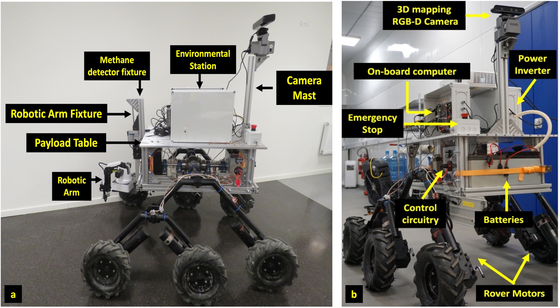
(a) Side view of KORE (left) (b) Isometric view of KORE (right) with a complete payload for MINAR6 campaign.
The MINAR6 3D mapping system is an improved version of InXSpace 3D with pannable cameras exploiting the state-of-the-art Robotic Operating System (ROS). With the mine environment serving as an analogue environment for investigation of subsurface geomorphology and astrobiology studies of samples, the need for a robotic arm for sample manipulation was necessitated. After MINAR5, it was also learned that methane is a critical gas of interest which is both relevant for safety in mines, as for extra-terrestrial explorations as potential biomarker. Thus, the rover was updated to incorporate methane monitoring capabilities.
Methane detection with electrochemical sensors limits detection to a narrow spatial resolution. To overcome the proximity issue, optical-based methane detection is an ideal instrument to measure methane concentrations. Methane detection with laser absorption spectroscopy has the capability to measure methane concentrations with a very fast response time (0.1 s) with a good measurement range up to 50 m. More sophisticated methods include hyperspectral imaging which provides a wider field of view and spatial resolution (Gålfalk et al., Reference Gålfalk, Olofsson, Crill and Bastviken2015) at the expense of higher operating costs and power. Hence the rover was fitted with the Laser Absorption Spectroscopy-based Methane detector. It is also of great importance to measure the presence of toxic gases in the mine environment. The rover is also fitted with an environmental monitoring station that could measure gases such as NO2, SO2, H2S, formaldehyde, CO, CO2, O3, O2, volatile organic compounds and particulates along with sensors to measure the environmental parameters such as the temperature, pressure and relative humidity around the rover. In the subsequent section, we discuss the steps which were crucial in the rover development and sensor integration.
Design and development
KORE is built with a robust design maximizing the use of COTS components and minimum custom-made parts to facilitate intelligibility to the research community to build such robotic platforms at a conservative budget without compromising the quality. The design ensures quick construction of the rover and improves portability of the rover to different field sites. The components used in the development of KORE are easily accessible and improves the serviceability of the rover in case of any failure. Moreover, the rover has the provision for easy and instant integration of more sensors as per the user requirements. This section is categorized in seven sections with each section describing in detail the features of the design.
Rover locomotion and suspension
Locomotion is the basis of any robotic explorer rover. The choice of locomotion mechanism for a rover is very specific to the terrain the rover has to traverse. In general, the terrains inside a mine or a cave can be extremely undulating, rocky, and steep. Hence there is a need to have a locomotion system with a very stable suspension to ensure the rover is able to climb obstacles and maintain its stability. Human intervention to access these rovers in case of failures is challenging and hence the design has to be very robust with a good traction power to ensure the rover is not caught in gullies or tumbles down a slope. These events can compromise the entire exploration as it can severely damage the instruments on the rover deck. Among the number of robotic missions with the capability of deploying rovers on extra-terrestrial surfaces, the six-wheel system rover has proven to be a reliable mechanism since its inception on Mars Pathfinder in 1997 (e.g. Matijevic, Reference Matijevic1996), Mars Exploration Rover in 2003 (e.g. Ralph Roncoli and Jan Ludwinski, Reference Ralph and Ludwinski2002) and Mars Science Laboratory in 2011 (e.g. Prakash et al., Reference Prakash2008). The extensive heritage of the six-wheel rocker-bogie design with its exceptional vehicle stability was a dominant factor in incorporating the mechanism to KORE. KORE utilizes commercial wheel-chair motors to locomote each wheel. The use of a brushless high torque wheel-chair motor provides exceptional power to KORE. The specifications of the motor and the wheels used in KORE is tabulated in Table 1.
Specifications of the electric motor and wheel used in KORE locomotion

Six-wheel rocker-bogie rovers allow each of the six-wheel assemblies to rotate for rover ‘arc-turn’ and ‘turn-in-place’ manoeuvres (Lindemann and Voorhees, Reference Lindemann and Voorhees2005). KORE does not have an assembly to rotate each of the individual wheels and hence cannot execute turn in place manoeuvres. It can perform an arc-turn manoeuvre or tank-turn manoeuvre by applying skid-steering. The rocker-bogie suspension allows each of the wheels to be in contact with the ground passively irrespective of the terrain and this allows the pressure acting on each wheel to be equilibrated. This ensures the rover does not sink into soft terrains which could result when the weight acting on the wheels is not spread uniformly through the six wheels. Also, the contact between each wheel and the terrain at all times ensures that the torque produced by each motor is utilized by the rover to propel through the rough terrain. Figure 6(a) shows the CAD modelled counter-rotating differential mechanism used in KORE. The counter differential mechanism ensures that when one side of the rocker-bogie is raised, the other side is pushed down to exert the maximum torque on contact with the ground.
(a) CAD model of the counter differential mechanism to be used in KORE (left) (b). Counter Differential of KORE before assembling on to aluminium chassis (right).

The gears used in this counter differential are miter gears, which are bevel gears with a gear ratio of 1:1. The role of these gears is to change the direction of rotation by transferring the motion to a perpendicular orientation and again transferring it to parallel orientation. Figure 6(b) shows the miter gear counter differential mechanism incorporated in KORE, with (Table 2) showing the specifications of the miter gear used in the counter differential assembly.
Specifications of the Miter gear used in KORE counter differential

A redundant fourth gear in the counter differential increases the surface area of the gear faces in contact and improves the load-bearing capacity of the differential. The improved load-bearing capacity of the differential is very crucial for the rover to withstand shocks when moving through rough terrains. The differential mechanism is mounted on the rover chassis to which the Rocker and Bogie are connected.
Rover mechanical design
The rover chassis constitutes the frame of the rover, which houses the counter differential, the payload table and the Rocker-Bogie. The rover chassis is subjected to impulsive load and shocks when the rover traverses' terrains. Hence there is a need for the chassis to absorb these impulses and shocks which are detrimental to the instruments on the rover.
Rover frame
The KORE frame is constructed from commercial aluminium profiles which provide greater flexibility to mount payloads and accessories such as the payload table. The optimal aluminium profile to build the frame was selected by performing simple static stress analysis on the Computer-Aided Design (CAD). Figure 7 shows the stress analysis results when KORE aluminium frame is subjected to distributed loads. The Solidworks® (http://www.solidworks.com) software was used in the CAD modelling and stress analysis. In Fig. 7 (top), the aluminium frame is subjected to a distributed load of 2000 N and in Fig. 7 (bottom) a distributed load of 1000 N is simulated to act on the aluminium frame (pink arrow) along the -Z direction. In both the studies, the extreme end aluminium profiles are fixed (green arrow) such that deformation can occur only on the inner two aluminium profile. The Rocker-Bogie pivoted along the extreme end profiles would add rigid support, while the inner two aluminium profiles would be void of support and hence studying their deformation under load is essential. A maximum threshold of 100 kg was defined to be payload carrying capability of the rover. Hence the simulation was performed with 1000 N and 2000 N distributed load on the frame.
Stress analysis of the aluminium frame along the XY-plane when subjected to distributed loads of 2000N (top) and 1000N (bottom). The colour scale shows the deformation in mm with red indicating maximum deformation zones and blue with the least deformation.

A deformation of maximum 0.51 mm is prone to occur when a 2000 N is distributed to act on the entire area of the aluminium frame and deformation of 0.26 mm is prone to occur in the later circumstance. The deformation study of the frame is critical as it is the centre point for the entire load acting on the chassis. The deformation is negligible for up to a load of 2000 N and it justifies the design of the aluminium frame.
Rover rocker and bogie
The Rocker constitutes the front arm that is connected directly to the front traction motors. The Bogie is the trailing arm that houses the rear motors of the rover. The rockers are connected to the differential and to the bogie pivot. The bogie pivot is a pivot bearing that holds the rocker to the bogie. The connecting points between the rocker and differential and rocker and bogie are shown in Fig. 8. The rocker and bogie carry the entire weight of the rover and hence they need to be rigid to maintain the stability of the rover. Commercial Steel tubing of 40 mm diameter and 2 mm wall thickness was used in the construction of the Rocker-Bogie structure. The Rocker-Bogie structure is made with a 2:1 ratio scale where the rocker arm length is twice the length of the bogie arm and the angle between the horizontal and the rocker-bogie wheel attachment is fixed at 45° and 135°, respectively. Figure 9 shows the Rocker-Bogie of KORE assembled and painted with anti-rust coating. Anti-rust coating is particularly critical for exploration of a salt mine. Halites increase corrosion of steel and this corrosion increases drastically on exposure to higher relative humidity. The influence of sodium chloride on the atmospheric corrosion of steel is discussed by Ericsson (Reference Ericsson1978). Figure 9 shows rust formation on a steel plate fixture of the Methane detector without anti-rust protection. The extensive rusting could be observed in a narrow timeframe of just 1 month once after the campaign and once the rover was exposed to ambient temperature and relative humidity conditions out of the mine.
Accelerated rusting observed on the methane detector fixture after taken to the surface.

Rocker-bogie with anti-rust paint. The second layer of paint was sprayed upon the anti-rust coating to improve the shelf life of the Rover Rocker-Bogie.

A motion study of the rocker-bogie assembly was performed using Solidworks® motion study tool to analyse the characteristics of the mechanism by simulating the rover motion over undulances. The CAD model of KORE chassis, shown in Fig. 10 (top) was subjected to motion analysis. The braking torque of the motors required was also simulated with a slope of 30° to obtain an estimate of the motor torque needed to actuate the rover. The braking torque for actuating the chassis is shown in the plot Fig. 10 (bottom). For a slope of 30° and mass of the chassis of approximately 80 kg without payload table, payload and batteries, the torque was estimated to be around 7.7 Nm. With all accessories mounted, the complete rover was estimated to weigh about 160 kg and a motor of torque twice the simulated calculation was needed.
CAD model (top) of the Rover Chassis which was subjected to motion analysis with simulated terrain in Solidworks® motion study. The model was also subjected to actuate along a 30° slope to calculate the braking torque, which gives an approximate idea of the motor torque needed, shown in the plot (bottom). The red box indicates the peak torque generated along the slope.

Rover payload table
The rover payload table is the mounting plate for the payloads and the rover computer. A commercial aluminium milled T-slot table is chosen as the rover payload table owing to its good load-bearing capacity at reduced weight. An important criterion of any vehicle design is to avoid increasing the height of the centre of gravity as it can severely compromise the vehicle stability. Hence it is of great importance to distribute the weight evenly and the T-slot aluminium table being lighter and stronger justifies its purpose as a payload table. Moreover, the milled T-Slots allow easy of mounting payloads by sliding M6 bolts through the grooves, to hold the payload to the payload table.
Rover electrical design
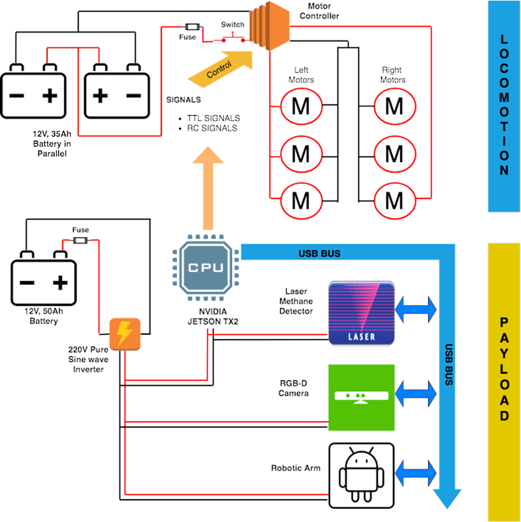
The KORE is furnished with three batteries to power the rover and the payload. The batteries used in KORE are sealed lead acid Gel batteries. Two 12 V, 35 Ah batteries are connected in parallel to provide 70 Ah capacity at 12 V for powering the six motors of the rover. A 12 V, 50 Ah battery is used to power the payload on the rover. The motors are controlled through a commercial motor driver, Sabertooth dual channel 60 A motor driver that supports a maximum current of 60 A on each channel. Three motors on either side of the rover are connected in parallel to the individual channels. The Sabertooth motor driver is very versatile for control as it can take inputs such as differential radio control inputs, Pulse Width Modulation (PWM) signals or Transistor-Transistor Logic (TTL) serial input to control the speed and direction of the motor. KORE is programmed to use both TTL serial input signals and radio control signals for rover control. The former is used to control the rover through the onboard computer using Internet. The latter is used to control the rover in close range through a standard 2.4 GHz telemetry link.
To power the payloads on the rover, KORE is furnished with a 600 W pure sine wave inverter that boosts the voltage from the 12 V, 50 Ah battery to provide a stable 220 V sine wave output. The availability of 220 V power sockets on the rover matches the standard requirement of most payloads. All the connections from the battery are provided with battery isolators and fuses to prevent any fire hazard or explosion in case of short circuit or misconnections. An additional emergency switch is used to cut the power to the motor driver in case of emergency situations. The flowchart, Fig. 11 discusses the complete electrical circuitry of KORE rover.
Locomotion and payload electrical circuit architecture of KORE.
Rover onboard computer
The onboard computer of KORE serves a multitude of purposes. The control of the rover, payloads and sensors are all interfaced to the rover onboard computer. The onboard computer is the backbone of the InXSpace 3D system discussed in the forthcoming section of the paper. To cater the Graphical processing required by InXSpace 3D and also to provide a large number of input/output ports for rover and payload control, the nVIDIA® Tegra TX2 processor with the embedded development kit is chosen as the onboard computer of the KORE rover. The specification of the onboard computer is highlighted in Table 3 and the onboard computer mounted on the rover is shown in Fig. 12.
GPIO pinout of onboard computer to connect control circuitry shown along with the relay board that controls the various payloads attached to rover such as the linear actuator, InXSpace 3D pan/tilt control and rover drive motor controller.

nVIDIA® Jetson TX2 specifications

InXSpace 3D mapping system
The InXSpace 3D system is built using the commercial RGB-D camera, Microsoft Kinect™ and dense SLAM software algorithms such as Kintinuous, ElasticFusion and RtabMap. All these softwares are based on visual SLAM using RGB-D data generated by the camera and use common frameworks such as OpenCV. A detailed comparison between Kintinuous and RtabMap is discussed by Altuntaş et al. (Reference Altuntaş, Uslu, Çakmak, Amasyalı and Yavuz2017). For the development of the new InXSpace 3D system, two RGB-D cameras were tested. The Microsoft Kinect™ that was used in the MINAR5 campaign was compared with the Orbbec Astra pro, a new RGB-D camera in the 3D camera market. The specifications of both these cameras are compared in Table 4.
Comparison between the commercial RGB-D cameras

The ARM architecture of the nVIDIA® Tegra TX2 processor, limits the driver availability for most devices. Orbbec Astra Pro suffers from a poor driver support and hence the first version of Microsoft Kinect™ was preferred owing to its compatibility with all the three algorithms used. The compromise made on choosing Microsoft Kinect™ in spite of better range of Orbbec Astra pro will be resolved with development of better driver support in the future work. The OpenNI driver is supported by most visual SLAM algorithms and it improves the versatility of the Microsoft Kinect™ camera. The following section discusses the setup of InXSpace 3D with calibration and testing before deployment on the KORE.
Setup
The nVIDIA® Tegra TX2 development kit is updated with Ubuntu 16.04 platform with Linux 4.4.38 kernel using the nVIDIA® Jetpack 3.2.1 for L4T system. The ubuntu repository for installing and building the visual SLAM algorithms is updated. ROS Kinetic is used in the GPU. System dependencies such as libraries of sqlite3, pcl and opencv are installed in the GPU. These dependencies are required to build the RtabMap package. The Kintinuous and ElasticFusion are not supported on the ARM architecture of nVIDIA® Tegra TX2 chipset and a separate laptop with nVIDIA® GPU is used to run these algorithms. The field of view of the Microsoft Kinect™ camera is 57° and 43°, respectively, in the horizontal and vertical directions and there is a need for a steerable system to rotate and tilt the camera to cover a wider field of view. A commercial camera panner with servo motors is used to adjust the camera rotation and tilt to produce a 3D map of the larger spatial area. Figure 13 shows the RGB-D Microsoft Kinect™ camera mounted on the camera panner.
Microsoft Kinect™ RGB-D camera connected to commercial photographic camera pan/tilt assembly. The pan/tilt system allows 15° of freedom in tilt axis in either direction and 360° of freedom in pan direction.

Calibration
The Microsoft Kinect™ camera uses two monocular camera, one which captures RGB data and the other which works with infrared. Both cameras need to be calibrated to obtain precise information from the RGB data and the depth data. A checkerboard is used to obtain the calibration parameters using a python-based calibration application for the ROS OS. Figure 14 shows the calibration checkerboard used to perform the calibration of the RGB-D camera.
The RGB-D camera was calibrated for both the RGB visual image and depth IR image using the checkerboard of known dimensions. The calibration factor thus obtained is input into the algorithms to autocorrect offsets.

Testing
The testing of the new InXSpace 3D system was performed in the corridor of the Inspire Lab, Luleå University of Technology, Sweden by moving the rover through the alley and mapping the environment. Figure 15 shows the 3D DEM map generated from the point clouds of InXSpace 3D. The DEM map is projected in the Z-axis with the elevation of the alley indicated in blue representing the floor and red representing the highest points, the ceiling. The open source CloudCompare software (http://www.danielgm.net/cc) is used to generate the DEM map from the point cloud. Also, the system was tested for its accuracy by measuring the size of the circular glass window by taking two points on the diagonal of the window in the 3D point cloud. The measured value obtained from the point clouds matches the physical measurement of the circular window with a negligible error of 0.003 m.
DEM point cloud of the laboratory corridor of the Department of Computer Science, Electrical and Space Engineering, Luleå University of Technology. The scale bar is in m.

Laser Methane detection system
The KORE rover uses a remote laser methane detection system from Hesai photonics, which is a portable instrument designed to be mounted on drones and vehicles for inspecting methane leaks from a point source. The methane detector that works based on absorption spectroscopy is pre-calibrated in the factory and is operable on field out of the box. However, the methane detector was tested and the readings were validated in laboratory conditions before mounting on the KORE rover. The detector provides a methane concentration output which is the integrated concentration of methane along the path of the laser beam. The methane detector is powered by the onboard power supply of the rover and the data from the instrument is collected by the nVIDIA® computer through serial communication. Table 5 shows the specifications of the methane detector.
Hesai Methane leak detector specifications

Rover Robotic Arm
The Robotic Arm is a very crucial payload of KORE that performs as a standalone payload and also serves as a self-sufficient platform to handle other payloads. A commercial robotic arm from Dobot (Gupta et al., Reference Gupta, Murali, Gandhi and Pinto2018) is used on KORE. The Robotic arm has a limited reach of maximum 320 mm and there is a need to bring the entire arm assembly down from the rover to collect samples on the ground. Hence, the need to have a linear actuator to house the robotic arm assembly was required. A 12 V linear actuator is housed on the rover, connected to the aluminium chassis by means of a fixture made from aluminium profiles and steel plates. Figure 16 shows the linear actuator fixture with the Robotic arm and (Table 6) lists some of the characteristics of the robotic arm.
Robotic arm assembly fixed to KORE chassis.

Specifications of the Robotic arm

Environmental station
The Environmental Station on the KORE Rover has a multitude of sensors measuring common air pollutants, particulate matter and environmental parameters such as temperature, pressure and relative humidity. The gases measured are NO2, SO2, H2S, formaldehyde, CO, CO2, O3, O2 and volatile organic compounds (VOC). Commercial grade Electrochemical sensors are employed in the measurement of these gases and the data are stored onboard the environmental station computer. The data can be accessed through the rover computer or also directly from the environmental station itself. The environmental station provides a vivid characteristic of the environment around the rover.
Figure 17 (left) shows KORE during testing in Luleå University of Technology, Sweden, where its mobility was tested by climbing a smooth terrain slope of 15°–30°. Also, KORE was tested for its stability by climbing down stairs as shown in Fig. 17 (right). These tests were performed before the MINAR6 campaign to check KORE performance in different terrains after which it was dis-assembled and shipped to the Boulby Mine in UK for commencing the subsurface exploration. The summary highlighting the specifications of KORE is elucidated in Table 7.
(left) KORE during testing at Luleå University of Technology, Sweden, where its mobility was analysed when traversing a slope path of 15°–30° (right) KORE climbing down stairs test its stability in rugged terrain.

Summary specifications of KORE

During the MINAR6 campaign, the rover was subjected to rigorous testing for mobility and the platform was deemed stable and endured traverses through slopes of more than 30°. There occured no scenario of parts to be replaced after the campaign, if such scenario needs to arise in future campaigns, the replacement of parts is very easy owning to utilization of COTS components. KORE can be dismantled in three major parts (the aluminium frame with differential, the Rocker-Bogies and the payloads) for easy transportation and quick reinstallation at the site of exploration (Fig. 18).
Three major components of KORE dismantlable for transportation to field site, red box – Rocker Bogie, blue box – aluminium frame with differential, purple box – payload.

Conclusions
Future exploration missions to Moon and Mars will significantly rely on technological advancements to enable subsurface investigations. To improve the technological readiness level (TRL) and the instrumentation and experiments to be carried out using the rover platform, it is important to develop and test such platform in analogues on earth. In this work, we had two main goals: (1) to design and develop a rover for subsurface exploration and (2) to test and use the rover for geomorphological, astrobiological and mining applications. Both goals have been achieved and the latter one will be discussed in Part II of this issue (Mathanlal et al., Reference Mathanlal, Bhardwaj, Vakkada Ramachandran, Zorzano, Martin-Torres, Cockell, Paling and Edwards2019). KORE has been designed and developed using COTS components which makes it versatile. Most of the components are commercially available, making it easier to provide fixes in case of any operational failure. In subsurface exploration, access to locations in the dark and identifying any unknown object is one of the main tasks; the RGB-D camera onboard KORE can 3D map the area in which it is operating even in the low light environment. This technology could be used by the mining industry in decision making regarding future mine expansions using 3D geomorphological mapping and safety and rescue operations such as identifying persons trapped inside debris. In future space missions, such semi-autonomous mapping and sample collecting platforms can enable quick and effective access to caves and other subsurface environments. KORE has the compatibility to mount more sensors and customize according to research requirements. This rover has proven to be a combination of reliable science value with reasonable cost which makes it more suitable for current subsurface exploration.
Acknowledgement
The authors of this paper would like to thank Kempe Foundation for its generous funding support to develop KORE, the workshop at the Teknikens Hus, Luleå, for their invaluable and unconditional support in helping with the fabrication of the Rover components and the organizers of the MINAR campaign comprising the UK Centre of Astrobiology, Dark Matter Research Facility and the Israel Chemicals Limited (ICL), UK.


 Open access